WO2010134461A1 - 保持器付きころ、保持器付きころ軸受および保持器 - Google Patents
保持器付きころ、保持器付きころ軸受および保持器 Download PDFInfo
- Publication number
- WO2010134461A1 WO2010134461A1 PCT/JP2010/058099 JP2010058099W WO2010134461A1 WO 2010134461 A1 WO2010134461 A1 WO 2010134461A1 JP 2010058099 W JP2010058099 W JP 2010058099W WO 2010134461 A1 WO2010134461 A1 WO 2010134461A1
- Authority
- WO
- WIPO (PCT)
- Prior art keywords
- plating layer
- cage
- ptfe
- roller
- hardness
- Prior art date
- Legal status (The legal status is an assumption and is not a legal conclusion. Google has not performed a legal analysis and makes no representation as to the accuracy of the status listed.)
- Ceased
Links
Images









Classifications
-
- F—MECHANICAL ENGINEERING; LIGHTING; HEATING; WEAPONS; BLASTING
- F16—ENGINEERING ELEMENTS AND UNITS; GENERAL MEASURES FOR PRODUCING AND MAINTAINING EFFECTIVE FUNCTIONING OF MACHINES OR INSTALLATIONS; THERMAL INSULATION IN GENERAL
- F16C—SHAFTS; FLEXIBLE SHAFTS; ELEMENTS OR CRANKSHAFT MECHANISMS; ROTARY BODIES OTHER THAN GEARING ELEMENTS; BEARINGS
- F16C9/00—Bearings for crankshafts or connecting-rods; Attachment of connecting-rods
- F16C9/02—Crankshaft bearings
-
- F—MECHANICAL ENGINEERING; LIGHTING; HEATING; WEAPONS; BLASTING
- F16—ENGINEERING ELEMENTS AND UNITS; GENERAL MEASURES FOR PRODUCING AND MAINTAINING EFFECTIVE FUNCTIONING OF MACHINES OR INSTALLATIONS; THERMAL INSULATION IN GENERAL
- F16C—SHAFTS; FLEXIBLE SHAFTS; ELEMENTS OR CRANKSHAFT MECHANISMS; ROTARY BODIES OTHER THAN GEARING ELEMENTS; BEARINGS
- F16C19/00—Bearings with rolling contact, for exclusively rotary movement
- F16C19/22—Bearings with rolling contact, for exclusively rotary movement with bearing rollers essentially of the same size in one or more circular rows, e.g. needle bearings
- F16C19/24—Bearings with rolling contact, for exclusively rotary movement with bearing rollers essentially of the same size in one or more circular rows, e.g. needle bearings for radial load mainly
- F16C19/26—Bearings with rolling contact, for exclusively rotary movement with bearing rollers essentially of the same size in one or more circular rows, e.g. needle bearings for radial load mainly with a single row of rollers
-
- F—MECHANICAL ENGINEERING; LIGHTING; HEATING; WEAPONS; BLASTING
- F16—ENGINEERING ELEMENTS AND UNITS; GENERAL MEASURES FOR PRODUCING AND MAINTAINING EFFECTIVE FUNCTIONING OF MACHINES OR INSTALLATIONS; THERMAL INSULATION IN GENERAL
- F16C—SHAFTS; FLEXIBLE SHAFTS; ELEMENTS OR CRANKSHAFT MECHANISMS; ROTARY BODIES OTHER THAN GEARING ELEMENTS; BEARINGS
- F16C19/00—Bearings with rolling contact, for exclusively rotary movement
- F16C19/22—Bearings with rolling contact, for exclusively rotary movement with bearing rollers essentially of the same size in one or more circular rows, e.g. needle bearings
- F16C19/44—Needle bearings
- F16C19/46—Needle bearings with one row or needles
-
- F—MECHANICAL ENGINEERING; LIGHTING; HEATING; WEAPONS; BLASTING
- F16—ENGINEERING ELEMENTS AND UNITS; GENERAL MEASURES FOR PRODUCING AND MAINTAINING EFFECTIVE FUNCTIONING OF MACHINES OR INSTALLATIONS; THERMAL INSULATION IN GENERAL
- F16C—SHAFTS; FLEXIBLE SHAFTS; ELEMENTS OR CRANKSHAFT MECHANISMS; ROTARY BODIES OTHER THAN GEARING ELEMENTS; BEARINGS
- F16C19/00—Bearings with rolling contact, for exclusively rotary movement
- F16C19/54—Systems consisting of a plurality of bearings with rolling friction
-
- F—MECHANICAL ENGINEERING; LIGHTING; HEATING; WEAPONS; BLASTING
- F16—ENGINEERING ELEMENTS AND UNITS; GENERAL MEASURES FOR PRODUCING AND MAINTAINING EFFECTIVE FUNCTIONING OF MACHINES OR INSTALLATIONS; THERMAL INSULATION IN GENERAL
- F16C—SHAFTS; FLEXIBLE SHAFTS; ELEMENTS OR CRANKSHAFT MECHANISMS; ROTARY BODIES OTHER THAN GEARING ELEMENTS; BEARINGS
- F16C33/00—Parts of bearings; Special methods for making bearings or parts thereof
- F16C33/30—Parts of ball or roller bearings
- F16C33/46—Cages for rollers or needles
- F16C33/4617—Massive or moulded cages having cage pockets surrounding the rollers, e.g. machined window cages
- F16C33/4623—Massive or moulded cages having cage pockets surrounding the rollers, e.g. machined window cages formed as one-piece cages, i.e. monoblock cages
- F16C33/4629—Massive or moulded cages having cage pockets surrounding the rollers, e.g. machined window cages formed as one-piece cages, i.e. monoblock cages made from metal, e.g. cast or machined window cages
-
- F—MECHANICAL ENGINEERING; LIGHTING; HEATING; WEAPONS; BLASTING
- F16—ENGINEERING ELEMENTS AND UNITS; GENERAL MEASURES FOR PRODUCING AND MAINTAINING EFFECTIVE FUNCTIONING OF MACHINES OR INSTALLATIONS; THERMAL INSULATION IN GENERAL
- F16C—SHAFTS; FLEXIBLE SHAFTS; ELEMENTS OR CRANKSHAFT MECHANISMS; ROTARY BODIES OTHER THAN GEARING ELEMENTS; BEARINGS
- F16C33/00—Parts of bearings; Special methods for making bearings or parts thereof
- F16C33/30—Parts of ball or roller bearings
- F16C33/46—Cages for rollers or needles
- F16C33/54—Cages for rollers or needles made from wire, strips, or sheet metal
- F16C33/542—Cages for rollers or needles made from wire, strips, or sheet metal made from sheet metal
- F16C33/543—Cages for rollers or needles made from wire, strips, or sheet metal made from sheet metal from a single part
- F16C33/546—Cages for rollers or needles made from wire, strips, or sheet metal made from sheet metal from a single part with a M- or W-shaped cross section
-
- F—MECHANICAL ENGINEERING; LIGHTING; HEATING; WEAPONS; BLASTING
- F16—ENGINEERING ELEMENTS AND UNITS; GENERAL MEASURES FOR PRODUCING AND MAINTAINING EFFECTIVE FUNCTIONING OF MACHINES OR INSTALLATIONS; THERMAL INSULATION IN GENERAL
- F16C—SHAFTS; FLEXIBLE SHAFTS; ELEMENTS OR CRANKSHAFT MECHANISMS; ROTARY BODIES OTHER THAN GEARING ELEMENTS; BEARINGS
- F16C33/00—Parts of bearings; Special methods for making bearings or parts thereof
- F16C33/30—Parts of ball or roller bearings
- F16C33/46—Cages for rollers or needles
- F16C33/56—Selection of substances
- F16C33/565—Coatings
-
- F—MECHANICAL ENGINEERING; LIGHTING; HEATING; WEAPONS; BLASTING
- F16—ENGINEERING ELEMENTS AND UNITS; GENERAL MEASURES FOR PRODUCING AND MAINTAINING EFFECTIVE FUNCTIONING OF MACHINES OR INSTALLATIONS; THERMAL INSULATION IN GENERAL
- F16C—SHAFTS; FLEXIBLE SHAFTS; ELEMENTS OR CRANKSHAFT MECHANISMS; ROTARY BODIES OTHER THAN GEARING ELEMENTS; BEARINGS
- F16C9/00—Bearings for crankshafts or connecting-rods; Attachment of connecting-rods
- F16C9/04—Connecting-rod bearings; Attachments thereof
-
- F—MECHANICAL ENGINEERING; LIGHTING; HEATING; WEAPONS; BLASTING
- F16—ENGINEERING ELEMENTS AND UNITS; GENERAL MEASURES FOR PRODUCING AND MAINTAINING EFFECTIVE FUNCTIONING OF MACHINES OR INSTALLATIONS; THERMAL INSULATION IN GENERAL
- F16C—SHAFTS; FLEXIBLE SHAFTS; ELEMENTS OR CRANKSHAFT MECHANISMS; ROTARY BODIES OTHER THAN GEARING ELEMENTS; BEARINGS
- F16C19/00—Bearings with rolling contact, for exclusively rotary movement
- F16C19/22—Bearings with rolling contact, for exclusively rotary movement with bearing rollers essentially of the same size in one or more circular rows, e.g. needle bearings
- F16C19/44—Needle bearings
- F16C19/46—Needle bearings with one row or needles
- F16C19/466—Needle bearings with one row or needles comprising needle rollers and an outer ring, i.e. subunit without inner ring
-
- F—MECHANICAL ENGINEERING; LIGHTING; HEATING; WEAPONS; BLASTING
- F16—ENGINEERING ELEMENTS AND UNITS; GENERAL MEASURES FOR PRODUCING AND MAINTAINING EFFECTIVE FUNCTIONING OF MACHINES OR INSTALLATIONS; THERMAL INSULATION IN GENERAL
- F16C—SHAFTS; FLEXIBLE SHAFTS; ELEMENTS OR CRANKSHAFT MECHANISMS; ROTARY BODIES OTHER THAN GEARING ELEMENTS; BEARINGS
- F16C2204/00—Metallic materials; Alloys
- F16C2204/52—Alloys based on nickel, e.g. Inconel
-
- F—MECHANICAL ENGINEERING; LIGHTING; HEATING; WEAPONS; BLASTING
- F16—ENGINEERING ELEMENTS AND UNITS; GENERAL MEASURES FOR PRODUCING AND MAINTAINING EFFECTIVE FUNCTIONING OF MACHINES OR INSTALLATIONS; THERMAL INSULATION IN GENERAL
- F16C—SHAFTS; FLEXIBLE SHAFTS; ELEMENTS OR CRANKSHAFT MECHANISMS; ROTARY BODIES OTHER THAN GEARING ELEMENTS; BEARINGS
- F16C2208/00—Plastics; Synthetic resins, e.g. rubbers
- F16C2208/20—Thermoplastic resins
- F16C2208/30—Fluoropolymers
- F16C2208/32—Polytetrafluorethylene [PTFE]
Definitions
- the present invention relates to a roller with a cage, a roller bearing with a cage, and a cage used in, for example, a support structure for a crankshaft and a connecting rod support structure for a four-wheeled vehicle, a two-wheeled vehicle, and a general-purpose engine. And a technique for solving excessive temperature rise.
- a roller with a cage is composed of a roller and a cage, and has a structure in which the outer peripheral surface of the roller is in line contact with the raceway surfaces of the inner ring and the outer ring. For this reason, it has the advantage that high load capacity and high rigidity can be obtained for a small bearing projected area. Accordingly, the roller with cage is widely used in various fields including automobiles.
- a roller with a cage of a sliding bearing or a rolling bearing is used for a large and small end of a two-wheeled vehicle. In the case of a two-cycle engine, the large and small ends are lubricated by a spray-like mixed liquid in which gasoline and engine oil are mixed.
- rollers with cages used copper plating or silver plating in order to prevent the outer diameter and width of the cage from being worn and excessive temperature rise.
- composite plating in which the base material is nickel as a main material and fine particles of fluororesin are uniformly dispersed and co-deposited has been proposed (Patent Document 1). This device is a countermeasure content from the viewpoint of preventing wear and excessive temperature rise under high-speed use conditions.
- a composite plating containing nickel as a main material and containing a fluororesin is formed on the cage for the purpose of preventing wear and excessive temperature rise for high speed.
- the wear of copper and silver plating in recent years is not severe in use conditions, but the plating dissolves (disappears) due to a chemical reaction due to the influence of lubricating oil, and the temperature of the cage may rise excessively. . In particular, it often occurs in bearings used in 4-cycle engines.
- the oil used is completely different between the 2-cycle engine and the 4-cycle engine.
- the 4-cycle engine the engine oil stored in the oil pan is pumped and lubricates each part of the engine, and then returns to the oil pan again.
- engine oil is mixed with fuel and adheres to the rotating and sliding parts, or each part of the engine is lubricated by pumping from the oil tank, and then enters the combustion chamber with the mixture and burns. To do.
- the performance required for the two-cycle engine oil and the four-cycle engine oil is greatly different due to the difference in the structure such as the difference in the lubrication mechanism and the valve mechanism.
- the major difference in composition between these 2-cycle engine oil and 4-cycle engine oil is the presence or absence of sulfated ash and zinc dialkyldithiophosphate (abbreviated as ZnDTP).
- ZnDTP zinc dialkyldithiophosphate
- the low sulfated ash content in the two-cycle engine oil is that the acid neutralization performance of the overbased detergent, which is the main factor of the ash content, is not required, and the ash content increases the combustion chamber deposits and can cause plug misfire. Because there is.
- ZnDTP is not prescribed for the two-cycle engine oil is that the two-cycle engine does not require anti-oxidation property of the oil, and because there is no valve mechanism, severe wear prevention performance is not required.
- ZnDTP is usually pyrolyzed at 150 to 200 ° C, but there is a report that the temperature around the piston and ring during high load operation exceeds 200 ° C. , Causing ring sticking. In order to prevent this piston contamination and ring sticking, a large amount of detergent is required, which is why ZnDTP is not added.
- the ZnDTP has antioxidation ability, corrosion prevention ability, load bearing performance, wear prevention ability and the like, and is widely used in engine oil and industrial lubricating oil as a so-called multifunctional additive.
- ZnDTP As a wear prevention mechanism of ZnDTP, (1) Sulfur and phosphorus in ZnDTP react with metals to form iron sulfide and phosphate films to prevent wear. (2) ZnDTP decomposes to form a polyphosphate film on the metal surface to prevent wear.
- the theory is powerful.
- the 4-cycle engine oil contains ZnDTP, which is an additive, and sulfur is contained in the components in this ZnDTP.
- this sulfur reacts with metal to form a film and has an anti-wear effect, but it has been found from various evaluations and market-collected products that copper plating and silver plating applied to the cage are ineffective did.
- the object of the present invention is to provide a surface treatment that is not affected by the additives contained in the oil used, to prevent wear of the cage and excessive temperature rise, and to improve the adhesion between the surface treatment layer and the substrate. It is intended to provide a roller with a cage and a bearing using the roller with a cage.
- the roller with cage according to the present invention is the roller with cage having a plurality of rollers and a ring-shaped cage having pockets respectively holding the rollers at a plurality of locations in the circumferential direction.
- a base plating layer is applied to at least one or both of the outer diameter surface and the width surface
- a Ni / PTFE plating layer containing nickel and PTFE is applied to the surface of the base plating layer.
- the “PTFE” is an abbreviation for polytetrafluoroethylene, which is a polymer of tetrafluoroethylene, which is a fluorocarbon resin composed of only fluorine atoms and carbon atoms. This fluorocarbon resin shape is a polygonal shape.
- the plating obtains the adhesion force by the bonding of the metals, the adhesion force is improved by the bonding of the metals having similar compositions. Since nickel has a property that it is difficult to react with additives compared to copper and silver, elution can be suppressed. Therefore, it is possible to prevent nickel or the like in the Ni / PTFE plating layer from being dissolved into the engine oil. Accordingly, the self-lubricating property of the Ni / PTFE plating layer prevents the cage from being worn and excessively heated, and allows the engine to operate for a long period of time.
- the base plating layer and the Ni / PTFE plating layer are provided on at least one or both of the outer diameter surface and the width surface of the cage, the wear of the outer diameter surface when the cage is an outer ring guide type.
- the plurality of rollers with cages are arranged close to each other in the axial direction, the width surfaces of adjacent cages are prevented from coming into contact with each other and being worn.
- the PTFE in the Ni / PTFE plating layer may be one in which PTFE particles are dispersed during nickel plating.
- the base plating layer may be a nickel plating layer. Since the nickel plating layer and the Ni / PTFE plating layer contain a common composition, that is, nickel, the composition in the vicinity of both layers gradually changes, and the interface between the nickel plating layer and the Ni / PTFE plating layer adheres without gaps. Can be made. Therefore, the adhesiveness is excellent over the base material, the nickel plating layer, and the Ni ⁇ PTFE plating layer.
- the adhesion strength of the plating is due to the bonding between metals, and by providing a nickel plating layer having a composition similar to that of the Ni / PTFE plating layer, the adhesion strength becomes higher than when the Ni / PTFE plating is directly processed on the cage.
- the surface roughness of the Ni / PTFE plating layer may be Ra 0.7 ⁇ m or less.
- Ra is the center line average roughness Ra defined by Japanese Industrial Standards.
- the wear amount of the plating itself tends to increase. This is because the unevenness of the roughness itself is higher and the surface roughness is easier to wear.
- by setting the surface roughness of the Ni / PTFE plating layer to Ra 0.7 ⁇ m or less it becomes possible to reduce the unevenness of the roughness itself and to reduce the wear amount of the plating itself. .
- the amount of PTFE of the Ni / PTFE plating layer applied to the surface of the base plating layer is 20 vol% or more and 35 vol% or less.
- the amount of PTFE in the Ni / PTFE plating layer is small, the friction coefficient is high and the sliding characteristics are inferior, and the amount of plating wear tends to be large. In particular, when the amount of PTFE is less than 20 vol%, wear becomes significant. On the contrary, when the amount of PTFE is too large, the hardness after heat treatment is low, so that the amount of wear tends to increase. Further, when a large amount of PTFE is contained, the cost increases. If the amount of PTFE exceeds 35 vol%, the hardness after heat treatment tends to be low, so the amount of wear tends to increase.
- the wear coefficient of the Ni / PTFE plating layer is 20 vol% or more and 35 vol% or less, the wear coefficient is low, the sliding property is excellent, and the plating wear amount can be reduced. Further, it becomes possible to reduce the manufacturing cost.
- a base plating layer is applied to the entire surface of the cage, the Ni / PTFE plating layer applied to the surface of the base plating layer is cured by heat treatment, and after the heat treatment of the Ni / PTFE plating layer,
- the hardness (this hardness is referred to as “plating hardness”) may be Hv400 or more and Hv700 or less.
- the hardness represented by the “Hv” is Vickers hardness.
- the additive when the additive is in the engine oil, the additive is decomposed to form a film on the metal surface to further prevent wear, so that the Ni / PTFE plating layer inhibits the effect of the additive. Absent.
- the plating hardness after heat treatment of the Ni ⁇ PTFE plating layer is set to Hv400 or more and Hv700 or less. The plating hardness is a value determined by the PTFE content and the quenching temperature. When the plating hardness after quenching of the Ni ⁇ PTFE plating layer was Hv400 or more and Hv700 or less, the difference in wear amount was within 0.001 mm, and the difference was not recognized.
- the wear resistance can be maintained.
- the wear amount is increased. If it exceeds Hv700, the hardness is too high and the plating layer may crack.
- the cage is subjected to carburizing, quenching, and tempering, and the surface hardness is in a range of Hv450 to Hv700, and the hardness difference between the surface hardness and the hardness of the Ni / PTFE plating layer may be Hv200 or less.
- Bearings used in the large end of the connecting rod of the engine and the planetary mechanism of the transmission are rotated, so that the cage rotates while causing an elliptical motion. Therefore, if the plating does not follow the elliptical deformation of the cage, cracking or peeling occurs in the plating.
- the deformation of the cage is affected by the rigidity of the cage, and changes depending on the hardness if the same material has the same shape.
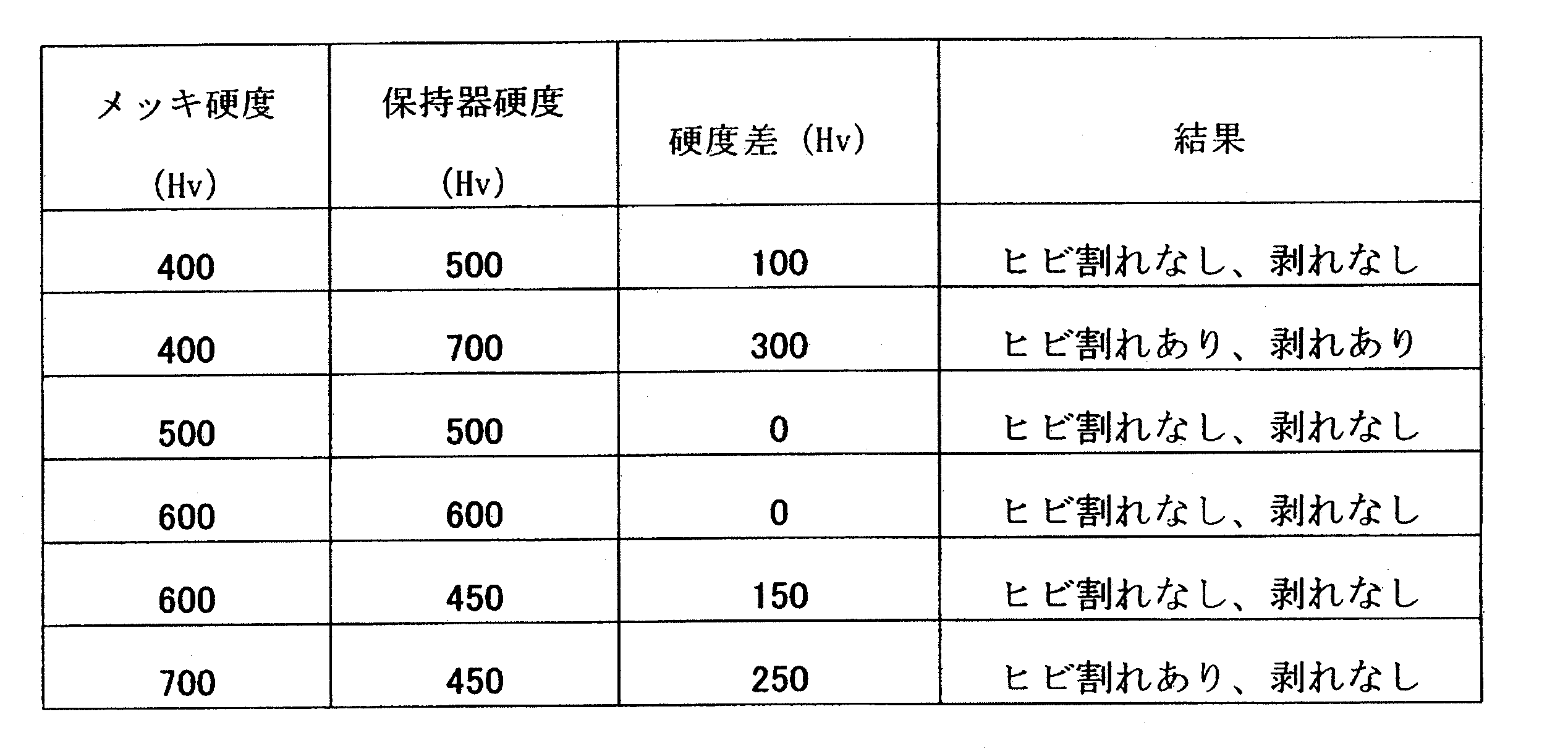
- the confirmation method is to manufacture a sample with the cage hardness and plating hardness up and down, apply a static load to the cage and give the deformation amount within the elastic deformation a predetermined number of times, and then there is no abnormality in the plating layer It was confirmed visually. As a result, when the hardness difference between the surface hardness of the cage and the plating hardness of the Ni / PTFE plating layer was Hv 200 or less, no cracking or peeling was observed in the plating.
- the total film thickness of the base plating layer and the Ni / PTFE plating layer may be 8 ⁇ m or more and 22 ⁇ m or less.
- the amount of wear of various plating layers was compared by crank motion, and the total film thickness was determined. As a result of carrying out this wear amount comparison, it was found that the Ni ⁇ PTFE plating layer of the present invention stopped in the initial wear for several tens of hours in the initial stage and did not progress thereafter. Since the wear amount was 7 ⁇ m, the lower limit of the Ni / PTFE plating layer was set to 7 ⁇ m.
- the total film thickness of the entire plating layer is set to 8 ⁇ m or more and 22 ⁇ m or less. Since the plating obtains the adhesion force by the bonding of the metals, the adhesion force is improved by the bonding of the metals having similar compositions. Since nickel has a property that it is difficult to react with additives compared to copper and silver, elution can be suppressed. When the total film thickness of the entire plating layer exceeds 22 ⁇ m, the cost increases.
- the total film thickness is less than 8 ⁇ m, for example, plating wear ⁇ exposure of cage base surface ⁇ sliding with connecting rod inner diameter ⁇ temperature rise, cage wear ⁇ excessive temperature rise in cage Connected.
- wear can be prevented by the self-lubricating performance of the Ni / PTFE plating layer.
- the total thickness of the plating layer is reduced to 8 ⁇ m or more and 22 ⁇ m or less, it is possible to reduce costs and prevent excessive temperature rise of the cage.
- the roller with a cage of the present invention is used for a cage.
- a roller bearing with a retainer includes any one of the above rollers with a retainer and a bearing ring on which the plurality of rollers roll.
- FIG. 12 A Sectional drawing of the roller with a retainer which concerns on 3rd Embodiment of this invention, (B) is a principal part top view of the retainer.
- the roller with a retainer according to the first embodiment of the present invention is used in, for example, a support structure for a crankshaft and a connecting rod support structure for a four-wheeled vehicle, a two-wheeled vehicle, and a general-purpose engine.
- the present invention is not limited to the crankshaft support structure and the connecting rod support structure.
- the roller with cage 50 includes a plurality of rollers 1 and a cage 2, and an outer member 31 that acts as an outer ring, and an inner member 32 that acts as an inner ring. It is intervened between.
- the inner member 32 is, for example, a shaft body supported by the roller 50 with a cage, and the roller 1 is in rolling contact with the outer peripheral surface thereof.
- a needle roller is used as the roller 1
- the end surface 1a of the roller 1 is a flat surface.
- the cage 2 has a ring shape having pockets 3 for holding the rollers 1 at a plurality of locations in the circumferential direction.
- the retainer 2 is provided with a Ni / PTFE plating layer 5 (described later) through a base plating layer 4 described later.
- the cage 2 is made of, for example, a press-formed product of a thin steel plate.
- the cage 2 is formed in a substantially cylindrical shape having a pair of flange portions 6, 6 that are annular portions bent toward the inner diameter side at both ends, and the axial central portion of the peripheral wall has a diameter.
- the small diameter portion 7 is narrowed inward in the direction.
- the retainer 2 has a plurality of circumferential column portions 8 that connect a pair of flange portions 6 and 6, and the space between adjacent column portions 8 and 8 is the pocket 3. It becomes.
- the cage 2 may have an annular portion such as a flat shape instead of the flange portions 6 and 6.
- a drop-off preventing protrusion 9 is formed at the small-diameter portion 7 at the center in the axial direction, and drop-off preventing protrusions 10 and 10 are formed at the large-diameter portions at both ends in the axial direction.
- An inclined edge 11 that guides the roller 1 in the circumferential direction between the protruding edges 9 and 10 at the opening edge of the pocket 3 in the column portion 8, from the radially outer side toward the central portion in the axial direction.
- An inclining edge 11 that is inclined inward is formed. The rollers 1 are prevented from slipping in and out by the falling-off preventing protrusions 9 and 10 and guided in the circumferential direction by the inclined edges 11.
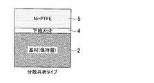
- the base plating layer 4 and the Ni / PTFE plating layer 5 will be described. As shown in FIGS. 1A and 1C, a base plating layer 4 is applied to the entire surface of the cage 2, and a Ni / PTFE plating layer 5 containing nickel and PTFE is provided on the surface of the base plating layer 4. Has been given.
- the base plating layer 4 is a nickel plating layer.
- the surface to be plated is the entire surface of the cage surface, and includes the width surface, inner diameter surface, and pocket of the cage.
- the film thickness ⁇ 1 of the nickel plating layer is, for example, 3 ⁇ 2 ⁇ m
- the film thickness ⁇ 2 of the Ni ⁇ PTFE plating layer 5 is, for example, 7 ⁇ m or more and 17 ⁇ m or less.
- the thickness ⁇ 1 of the nickel plating layer is not limited to 3 ⁇ 2 ⁇ m.
- the total film thickness ⁇ a of the nickel plating layer and the Ni ⁇ PTFE plating layer 5 is 8 ⁇ m or more and 22 ⁇ m or less.
- the total film thickness ⁇ a is 8 ⁇ m or more and 22 ⁇ m or less.
- the amount of wear of various plating layers was compared with the same crank motion motion as the actual machine, and the total film thickness was determined.
- FIG. 2 it was found from the results that the nickel plating layer and the Ni ⁇ PTFE plating layer 5 of the present invention stopped in the initial wear in the initial tens of hours and did not progress thereafter. Further, since the wear amount was 7 ⁇ m, the thinnest film thickness (lower limit) of the Ni / PTFE plating layer 5 was set to 7 ⁇ m.
- the cost will increase.
- the total film thickness is less than 8 ⁇ m, for example, plating wear ⁇ cage exposure ⁇ sliding with connecting rod inner diameter ⁇ temperature rise, cage wear ⁇ cage excessive temperature rise leads to problems.
- wear can be prevented by the self-lubricating performance of the Ni / PTFE plating layer.
- the total film thickness ⁇ a of the entire plating layer 8 ⁇ m or more and 22 ⁇ m or less it is possible to reduce costs and prevent excessive temperature rise of the cage.
- PTFE in the Ni / PTFE plating layer 5 is obtained by dispersing and co-depositing PTFE fine particles (indicated by black dots in the figure) in a base material mainly composed of nickel.
- the amount of PTFE of the Ni ⁇ PTFE plating layer 5 is defined as 20 vol% or more and 35 vol% or less. The determination of the PTFE amount will be described.
- the friction coefficient was measured by a Sabang test.
- the Sabang test is a test for comparative evaluation of the amount of wear. For example, as shown in FIG.
- the Sabang test machine SM includes a test piece mounting portion 19 for attaching the test piece m1, and a rotating portion 20 for rotating the test piece m1 attached to the test piece mounting portion 19.
- the test piece m1 attached to the test piece attachment portion 19 has a load load portion 21 for applying a constant load.
- the load load unit 21 applies a predetermined load to the test piece m 1 by an urging means such as a spring, and the load amount is measured by the load cell 22.
- steel for machine structural use such as Japanese Industrial Standard SCM415 is applied as the mating member 23 to be brought into sliding contact with the test piece m1 in the load applying portion 21.
- SCM415 Japanese Industrial Standard
- a felt pad 24 is provided inside the test piece mounting portion 19, and the felt pad 24 is brought into contact with the peripheral surface of the test piece m 1, and the test piece m 1 is rotated by the rotating portion 20, whereby felt pad refueling is performed. Is called.
- the amount of wear can be measured by attaching the test piece m1 to the test piece attachment portion 19, rotating the rotating portion 20 while applying a load to the test piece m1, and sliding the test piece m1 in sliding contact with the mating member 23.
- the test conditions are as follows. Sliding speed: 0.05 m / s, 5.0 m / s Surface pressure: 0.5GPa Time: 30 min (5.0 m / s), 60 min (0.05 m / s) Lubricant: Mobile Velocity No. 3 (VG2) As a result, as shown in FIG. 4B, it was found that the friction coefficient decreases as the amount of PTFE increases in the Ni ⁇ PTFE plating layer 5.
- the PTFE amount of the Ni ⁇ PTFE plating layer 5 is defined as 20 vol% or more and 35 vol% or less from the result of comparison of the friction coefficient and the wear amount.
- the PTFE amount By defining the PTFE amount in this way, the friction coefficient is low, the sliding property is excellent, and the plating wear amount can be reduced. Further, it becomes possible to reduce the manufacturing cost. Therefore, the self-lubricating property of the Ni / PTFE plating layer 5 prevents the cage 2 from being worn and excessively heated, and allows the engine or the like to operate for a long time.
- the surface roughness of the Ni / PTFE plating layer 5 is set to Ra 0.7 ⁇ m or less.
- Ra is a center line average roughness Ra defined by Japanese Industrial Standards, and is measured according to the standard of JIS 0601-1976 surface roughness.
- the centerline average roughness is obtained by extracting a portion of the measurement length L from the roughness curve in the direction of the centerline, setting the centerline of this extraction as the X axis, the direction of the vertical magnification as the Y axis, and the roughness curve as y.
- the hardness of the Ni / PTFE plating layer 5 will be described.
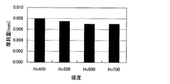
- the Ni ⁇ PTFE plating layer 5 is cured by heat treatment, and the plating hardness after the heat treatment of the Ni ⁇ PTFE plating layer 5 is set to Hv400 or more and Hv700 or less, so that the wear resistance can be maintained.
- wear comparison was performed under the same test conditions using the same roller with cage as when the total film thickness ⁇ a was determined.
- the plating hardness of Hv400 or more and Hv700 or less is a value determined by the PTFE content and the quenching temperature.
- the test sample was manufactured by changing the quenching temperature while keeping the PTFE amount constant. As shown in FIG. 6, from this result, if the plating hardness after quenching of the Ni ⁇ PTFE plating layer 5 is Hv400 or more and Hv700 or less, the difference in wear amount is within 0.001 mm, and the difference is not recognized. there were. When the plating hardness after quenching of the Ni ⁇ PTFE plating layer 5 is less than Hv400, the amount of wear increases. If it exceeds Hv700, the hardness is too high and the plating layer may crack.
- the hardness difference between the Ni / PTFE plating layer 5 and the cage 2 will be described.
- the cage 2 is subjected to carburizing, quenching and tempering, and the surface hardness is in the range of Hv450 to Hv700, and the hardness difference between the surface hardness and the plating hardness of the Ni / PTFE plating layer 5 is determined.
- Hv is 200 or less. Bearings used in the connecting rod large end portion of the engine and the planetary mechanism portion of the transmission are swung, so that the cage 2 rotates while causing an elliptical motion. Therefore, if the plating does not follow the elliptical deformation of the cage 2, cracking or peeling occurs in the plating.
- the deformation of the cage 2 is affected by the rigidity of the cage 2 and changes depending on the hardness if the shape and material are the same. Therefore, the influence of cage hardness and plating hardness was confirmed.
- the confirmation method is to make a sample with the cage hardness and plating hardness up and down, load the cage 2 with a static load, and give the amount of deformation within the elastic deformation (cage deformation 0.5 mm) 10,000 times. After that, the plating layer was visually checked for abnormalities. As a result, as shown in Table 1, when the hardness difference between the surface hardness of the cage and the plating hardness of the Ni / PTFE plating layer 5 was Hv 200 or less, no cracking or peeling was observed in the plating.
- the dissolution of the surface treatment will be described. It was confirmed by an immersion test that the metal component of the Ni / PTFE plating layer 5 according to the embodiment of the present invention does not dissolve under the high temperature condition of the 4-cycle engine oil. As shown in FIG. 7, in the conventional copper / silver plating, a large amount of element is detected from the oil along with the immersion time. On the other hand, the elements related to the Ni / PTFE plating layer 5 and the base plating layer 4 were not detected even when 200 hours passed in the embodiment.
- the base plating layer 4 was applied to the cage 2, and the Ni / PTFE plating layer 5 was further applied to the surface of the base plating layer 4. Since nickel has a property that it is difficult to dissolve in the additive (it is difficult to react), nickel or the like in the Ni / PTFE plating layer 5 can be prevented from being dissolved into the engine oil. Further, by providing the base plating layer 4 between the Ni / PTFE plating layer 5 and the base material (retainer), the adhesion strength between the base material and the Ni / PTFE plating layer 5 is improved, and plating peeling is prevented. (Since plating is obtained by bonding between metals, adhesion is improved by bonding between metals having similar compositions).
- the self-lubricating action of PTFE in the Ni / PTFE plating layer 5 reduces the friction coefficient of plating and improves the wear resistance. Accordingly, the self-lubricating performance of the Ni / PTFE plating layer 5 can prevent wear.
- the nickel plating layer as the base plating layer 4 and the Ni / PTFE plating layer 5 contain a common composition, that is, nickel, the composition in the vicinity of both layers gradually changes, and the nickel plating layer and the Ni / PTFE plating layer 5 Can be brought into close contact with no gap. Therefore, the adhesiveness is excellent over the base material, the nickel plating layer, and the Ni / PTFE plating layer 5. As described above, the adhesion is improved because the bonding between the metals is strengthened by providing a plating having a similar composition between them. Further, by setting the surface roughness of the Ni / PTFE plating layer 5 to Ra 0.7 ⁇ m or less, it is possible to reduce the unevenness of the roughness itself and to reduce the wear amount of the plating itself.
- the base plating layer 4 and the Ni / PTFE plating layer 5 are applied only to the width surface 2a and the outer diameter surface 2b of the cage 2.
- adjacent cages 2 and 2 may come into contact with each other at the width surface 2a, but the underlying plating layer of the width surface 2a in the cage 2 4 and the Ni / PTFE plating layer 5 can reduce wear due to relative contact of the cage 2, and can have a long life.
- the outer diameter surface 2 b of the cage 2 may come into contact with the outer member.
- the base plating layer 4 and the Ni / PTFE plating layer provided on the outer diameter surface 2 b are used. 5, the wear of the outer diameter surface 2b can be prevented.
- the base plating layer 4 and the Ni / PTFE plating layer 5 may be provided only on the width surface 2a of the cage 2 or only on the outer diameter surface 2b.
- the base plating layer 4 and the Ni / PTFE plating layer 5 may be applied to the entire cage. In this case, the plating layer is attached to the roller guide surface of the cage pocket 3, so that the wear of the roller 1 can be reduced. Therefore, it is possible to reduce the man-hour of the entire plating operation.
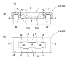
- the retainer 2A of the roller with retainer 50B according to the third embodiment shown in FIG. 9 has a guide protrusion that projects substantially perpendicularly toward the inner diameter side at both axial ends of the pocket 3 on the peripheral wall to guide the end face 1a of the roller 1.
- the piece 12 is formed integrally. Since the roller end face 1a is guided by the guide projection piece 12, the guide face 12a of the roller end face 1a by the cage 2A extends to the inner diameter side or shifts to the inner diameter side. Therefore, the roller end surface 1a is supported without being detached from the guide surface 12a toward the inner diameter side until the inclination angle of the roller 1 becomes relatively large.
- the roller end surface 1a can be prevented from coming off by the guide protrusion 12 regardless of the roller length with respect to the width of the cage 2A.
- the base plating layer 4 is applied to the entire surface of the cage 2 ⁇ / b> A, and the above-described Ni / PTFE plating layer 5 is applied to the surface of the base plating layer 4. Since the base plating layer 4 is also applied to the guide surface 12a of the guide protrusion 12, and the Ni / PTFE plating layer 5 is applied to the surface of the base plating layer 4 of the guide surface 12a, the roller end surface 1a Wear reduction can be achieved.
- the retainer 2B of the roller with retainer 50C according to the fourth embodiment shown in FIG. 10 is obtained by applying a nickel plating layer as a base plating layer 4 to the entire surface and combining PTFE 13 with the nickel plating surface layer. is there. According to the present embodiment, it is possible to obtain the same effects as those of the above-described embodiments with a smaller amount of PTFE than that in which the PTFE of FIG. 3 is uniformly dispersed. Thus, the amount of PTFE can be reduced, so that the manufacturing cost can be reduced.
- a roller with a cage 50D according to the fifth embodiment in FIG. 11 includes a plurality of rollers 1 and first and second cages 2C and 15.
- FIG. 11A is a cross-sectional view of the roller with cage cut along a plane including the axis L1.
- FIG. 11B is a cross-sectional view taken along line AA in FIG.
- the first cage 2C has the same configuration as the cage 2 of the first embodiment described above with reference to FIGS.
- a base plating layer 4 and a Ni / PTFE plating layer 5 are applied to the entire surface of the first cage 2C.
- the second retainer 15 is a ring-shaped member having a flat surface, and a pocket 15a for retaining the roller 1 is formed.
- the entire surface of the second cage 15 is provided with a base plating layer 4 and a Ni / PTFE plating layer 5.
- the second cage 15 is disposed on the inner peripheral surface of the flange portion 6 of the first cage 2C via a radial gap.
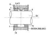
- FIG. 12 shows a bearing using the roller with cage according to any of the above embodiments.
- This roller bearing with cage is composed of the roller with cage 50 (50A, 50B, 50C) having any one of the above-described configurations and the race ring 14 to which the plurality of rollers 1 are in rolling contact.
- the outer ring is used as the race ring 14.
- the roller bearing with a cage may be configured to include one or both of the outer ring and the inner ring (or shaft Sh).
- FIG. 13 is a cross-sectional view of an essential part of a bearing for a connecting rod large end of an engine using a roller with a cage. Any one of the rollers with cage 50 according to the present invention is applied to the support bearings 16BR and 16BR for the crankshaft 16, the bearing of the connecting portion 17 between the connecting rod CR and the crankshaft 16, that is, the connecting rod large end bearing.
Landscapes
- Engineering & Computer Science (AREA)
- General Engineering & Computer Science (AREA)
- Mechanical Engineering (AREA)
- Rolling Contact Bearings (AREA)
Abstract
Description
一般に二輪車の大小端用には、滑り軸受または転がり軸受の保持器付きころが使用されている。2サイクルエンジンの場合、大小端部は、ガソリンとエンジンオイルとを混合させた噴霧状の混合液によって潤滑される。したがって滑り軸受では、摩耗や過度の昇温が発生するため、保持器付きころ、シェルラジアル軸受等の転がり軸受が使用されている。ただし、使用される転がり軸受で保持器付きころは、保持器外径や幅面の摩耗や過度の昇温防止のために、銅メッキや銀メッキが使用されていた。
銅メッキや銀メッキで耐えられない高速回転では、母材はニッケルを主要素材としフッ素樹脂の微粒子を均一に分散共析させた複合メッキが提案されている(特許文献1)。この考案は、高速使用条件による摩耗や過度の昇温の防止を視点とした対策内容である。
しかしながら、近年ではエンジンの燃費向上のため、4サイクルエンジンの支持部(例えば、コンロッド大端部)の滑り軸受が転がり軸受(保持器付きころ)へ置き換わっている。この4サイクルエンジンへの転がり軸受の適用が、課題の発端である。
(1)ZnDTP中の硫黄やりんが金属と反応して硫化鉄やりん酸塩の皮膜を作り摩耗を防ぐ。
(2)ZnDTPが分解して金属表面にポリフォスフェートの膜を生成し摩耗を防ぐ。
という説が有力である。
以上のように、4サイクルエンジンオイルには、添加剤であるZnDTPが入っており、このZnDTP中の成分に硫黄が入っている。摩耗防止機構として、この硫黄が金属と反応し皮膜を作り摩耗防止効果があるとのことだが、保持器に施す銅メッキや銀メッキでは効果が低いことが、種々の評価及び市場回収品から判明した。
前記「PTFE」とは、ポリテトラフルオロエチレン(Polytetrafluoroethylene)の略称であり、テトラフルオロエチレンの重合体で、フッ素原子と炭素原子のみから成るフッ化炭素樹脂である。このフッ化炭素樹脂形状は多角形状となっている。
Ni・PTFEメッキ層のPTFE量を20vol%以上35vol%以下と規定することで、摩耗係数が低く摺動特性に優れ、メッキ摩耗量を低くすることができる。さらに製造コストの低減を図ることが可能となる。
また、Ni・PTFEメッキ層の熱処理後のメッキ硬度をHv400以上Hv700以下としている。前記メッキ硬度は、PTFEの含有量と焼入れ温度で決定する値である。
Ni・PTFEメッキ層の焼入れ後のメッキ硬度がHv400以上Hv700以下であれば、摩耗量の差は0.001mm以内であり、差が認められない結果であった。このようにNi・PTFEメッキ層の焼入れ後のメッキ硬度をHv400以上Hv700以下に規定することにより、耐摩耗性を持続することができる。Ni・PTFEメッキ層の焼入れ後のメッキ硬度がHv400未満では、摩耗量が大きくなる。Hv700を超えると、硬度が高すぎてメッキ層がヒビ割れる可能性がある。
確認方法は、保持器硬度とメッキ硬度を上下に振ったサンプルを製作し、保持器に静的な荷重を負荷させ、弾性変形内の変形量を所定回数与えた後に、メッキ層に異常がないか目視確認した。その結果、保持器の表面硬度と、Ni・PTFEメッキ層のメッキ硬度との硬度差がHv200以下であれば、メッキに割れや剥れは認められなかった。
また、下地メッキ層の膜厚を例えば3±2μmとし、Ni・PTFEメッキ層の膜厚を例えば7μm以上17μm以下とすることで、メッキ層全体の総膜厚を8μm以上22μm以下にする。
メッキは金属同士の結合により密着力を得ているため、組成の近い金属同士の結合により密着力が向上する。ニッケルは銅・銀に比べ添加剤と反応し難い性質を持つため、溶出を抑制することが可能となる。
メッキ層全体の総膜厚が22μmを超える場合、コスト上昇につながる。総膜厚が8μmよりも薄い場合、例えば、メッキ摩滅→保持器基材表面の露出→コンロッド内径との摺動→温度上昇、保持器摩耗→保持器に過度の昇温、という流れで不具合につながる。
この発明の保持器付きころでは、Ni・PTFEメッキ層の自己潤滑性能により摩耗防止が可能となる。特に、メッキ層全体の総膜厚を8μm以上22μm以下にすることで、コスト低減を図ると共に、保持器の過度の昇温を防止できる。
図1(A)に示すように、保持器付きころ50は、複数のころ1と保持器2とを備えており、外輪として作用する外方部材31と、内輪として作用する内方部材32との間に介装されている。内方部材32は、例えば、この保持器付きころ50が支持する軸体であり、その外周面に、ころ1が転接するものとされている。ころ1は例えば針状ころが適用され、このころ1の端面1aを平坦面としている。図1(A)、(B)に示すように、保持器2は、円周方向の複数箇所に、前記各ころ1をそれぞれ保持するポケット3を有するリング状のものである。この保持器2に、後述する下地メッキ層4を介して、Ni・PTFEメッキ層5(後述する)を施している。
図1(A)、(C)に示すように、保持器2の表面全体に下地メッキ層4を施し、この下地メッキ層4の表面に、ニッケルとPTFEとを含むNi・PTFEメッキ層5を施している。前記下地メッキ層4はニッケルメッキ層である。メッキを処理する面は、保持器表面の全面であり、同保持器の幅面、内径面、ポケットも含む。
前記ニッケルメッキ層の膜厚δ1を例えば3±2μmとし、Ni・PTFEメッキ層5の膜厚δ2を例えば7μm以上17μm以下としている。ただし、ニッケルメッキ層の膜厚δ1は3±2μmに限定されるものではない。これらニッケルメッキ層およびNi・PTFEメッキ層5の総膜厚δaを8μm以上22μm以下としている。
実際の保持器付きころ(内径28mm×外径34mm×幅17mm)を用い、実機と同じクランクモーション運動で、各種メッキ層の摩耗量比較を実施し、総膜厚を決定した。図2に示すように、この結果から本発明のニッケルメッキ層およびNi・PTFEメッキ層5は、初期の数十時間で初期摩耗が止まり、それ以降は摩耗が進行しないことが判明した。また、摩耗量が7μmであったため、Ni・PTFEメッキ層5の最薄膜厚(下限値)を7μmとした。
PTFE量の決定について説明する。
Ni・PTFEメッキ層5のPTFE量の最適値を決定するために、サバン試験で摩擦係数を測定した。サバン試験とは、摩耗量の比較評価を行う試験である。例えば、図4(A)に示すように、サバン試験機SMは、試験片m1を取り付ける試験片取付け部19と、この試験片取付け部19に取り付けた試験片m1を回転させる回転部20と、試験片取付け部19に取り付けた試験片m1に一定の荷重を負荷する荷重負荷部21とを有する。荷重負荷部21は、ばね等の付勢手段によって所定の荷重を試験片m1に負荷し、その荷重量はロードセル22によって測定される。荷重負荷部21のうち試験片m1にすべり接触させる相手材23として、例えば日本工業規格SCM415等の機械構造用鋼が適用される。ただしSCM415に限定されるものではない。試験片取付け部19の内部には、フェルトパット24が設けられ、このフェルトパット24を試験片m1の周面に当接させ回転部20によりこの試験片m1を回転させることでフェルトパット給油が行われる。試験片m1を試験片取付け部19に取り付け、試験片m1に荷重を負荷しつつ回転部20を回転させ、同試験片m1を相手材23とすべり接触させることにより摩耗量を測定し得る。
この試験条件は以下の通りである。
すべり速度 : 0.05m/s 、 5.0m/s
面圧:0.5GPa
時間:30min(5.0m/s) 、 60min(0.05m/s)
潤滑油:モービルベロシティNo.3(VG2)
その結果、図4(B)に示すように、Ni・PTFEメッキ層5中、PTFE量が多い方が摩擦係数が下がることが判明した。
以上の摩擦係数と摩耗量比較の結果から、PTFE量には最適領域があることが判明した。この発明の実施形態では、摩擦係数と摩耗量比較の結果からNi・PTFEメッキ層5のPTFE量を20vol%以上35vol%以下と規定した。このようにPTFE量を規定することで、摩擦係数が低く摺動特性に優れ、メッキ摩耗量を低くすることができる。さらに製造コストの低減を図ることが可能となる。したがって、Ni・PTFEメッキ層5の自己潤滑性により保持器2の摩耗、過度の昇温を防止し、エンジン等を長期に稼動させることができる。
この発明の実施形態では、Ni・PTFEメッキ層5の表面粗さはRa0.7μm以下としている。
「Ra」は、日本工業規格で規定される中心線平均粗さRaであり、JIS 0601-1976表面粗さの規格に準拠して測定する。この中心線平均粗さは、粗さ曲線からその中心線の方向に測定長さLの部分を抜き取り、この抜き取りの中心線をX軸、縦倍率の方向をY軸とし、粗さ曲線をy=f(x)で表したとき、次の式で与えられるRaの値をマイクロメートル単位で表したものである。

この実施形態では、Ni・PTFEメッキ層5を熱処理により硬化させ、このNi・PTFEメッキ層5の熱処理後のメッキ硬度をHv400以上Hv700以下とすることにより、耐摩耗性を持続することができる。Ni・PTFEメッキ層5のメッキ硬度の最適値を決定するために、総膜厚δaを決定した際と同じ保持器付きころで同じ試験条件で摩耗比較を実施した。メッキ硬度のHv400以上Hv700以下は、PTFEの含有量と焼入れ温度とで決定する値である。したがって、試験サンプルは、PTFE量を一定にして、焼入れ温度を変更して製作した。
図6に示すように、この結果からNi・PTFEメッキ層5の焼入れ後のメッキ硬度がHv400以上Hv700以下であれば、摩耗量の差は0.001mm以内であり、差が認められない結果であった。Ni・PTFEメッキ層5の焼入れ後のメッキ硬度がHv400未満では、摩耗量が大きくなる。Hv700を超えると、硬度が高すぎてメッキ層がヒビ割れる可能性がある。
この発明の実施形態では、保持器2は、浸炭焼入れ焼戻しが施され、表面硬度がHv450以上Hv700以下の範囲であり、この表面硬度と、Ni・PTFEメッキ層5のメッキ硬度との硬度差をHv200以下としている。
エンジンのコンロッド大端部やトランスミッションの遊星機構部に使用される軸受は、振り回される運動のため、保持器2は楕円運動を起こしながら自転している。そのため、保持器2の楕円変形にメッキが追従しなければ、メッキにヒビ割れや剥れが発生する。この保持器2の変形には、保持器2の剛性が影響し形状・材料が同じであれば、硬度によって変化する。そのため、保持器硬度とメッキ硬度の影響を確認した。確認方法は、保持器硬度とメッキ硬度を上下に振ったサンプルを製作し、保持器2に静的な荷重を負荷させ、弾性変形内の変形量(保持器変形0.5mm)を10000回与えた後に、メッキ層に異状がないか目視確認した。その結果、表1に示すように、保持器の表面硬度と、Ni・PTFEメッキ層5のメッキ硬度との硬度差がHv200以下であれば、メッキに割れや剥れは認められなかった。
この発明の実施形態に係るNi・PTFEメッキ層5の金属成分等が、4サイクルエンジンオイルの高温条件下で溶解しないことを浸漬試験で確認した。図7に示すように、従来の銅・銀メッキは浸漬時間と共に油中から多くの元素量が検出されている。これに対して、実施形態のものは200時間経過しても、Ni・PTFEメッキ層5および下地メッキ層4に関係した元素は検出されなかった。
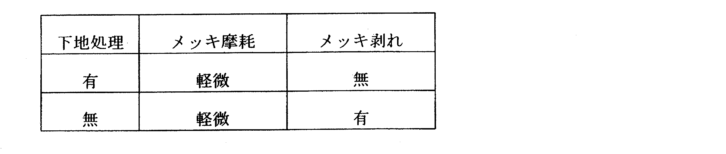
この発明の実施形態のものは、下地処理としてニッケルメッキを施した。下地メッキ有無による密着力を、実際の保持器付きころ(内径28mm×外径34mm×幅17mm)を用い、実機と同じクランクモーション運動で比較を実施した。その結果、表2に示すように、下地にニッケルメッキを施さない従来製品は、試験後にメッキの摩耗と剥れが認められた。一方、前記下地処理を施した実施形態のものは、試験後に軽微な摩耗は認められたが、剥れは認められなかった。このことから、メッキの密着力向上には下地処理が必要であることが判明した。
2,2A,2B…保持器
3…ポケット
4…下地メッキ層
5…Ni・PTFEメッキ層
13…PTFEメッキ層
14…外輪
15…第2の保持器
Claims (13)
- 複数のころと、円周方向の複数箇所に、前記各ころをそれぞれ保持するポケットを有するリング状の保持器とを備えた保持器付きころであって、
前記保持器の全表面のうち、少なくとも外径面および幅面のいずれか一方または両方に下地メッキ層を施し、この下地メッキ層の表面に、ニッケルとPTFEとを含むNi・PTFEメッキ層を施した保持器付きころ。 - 請求項1において、前記Ni・PTFEメッキ層におけるPTFEは、ニッケルメッキ中にPTFE粒子が分散しているものである保持器付きころ。
- 請求項1において、前記下地メッキ層はニッケルメッキ層である保持器付きころ。
- 請求項1において、前記Ni・PTFEメッキ層の表面粗さをRa0.7μm以下とした保持器付きころ。
- 請求項1において、下地メッキ層としてニッケルメッキ層を施し、この下地メッキ層の表面に施された前記Ni・PTFEメッキ層のPTFE量を20vol%以上35vol%以下とした保持器付きころ。
- 請求項1において、前記保持器の全表面に下地メッキ層を施し、この下地メッキ層の表面に施された前記Ni・PTFEメッキ層を熱処理により硬化させ、このNi・PTFEメッキ層の前記熱処理の後の硬度をHv400以上Hv700以下とした保持器付きころ。
- 請求項6において、前記保持器は、浸炭焼入れ焼戻しが施され、表面硬度がHv450以上Hv700以下の範囲であり、この表面硬度と、前記Ni・PTFEメッキ層の硬度との硬度差をHv200以下とした保持器付きころ。
- 請求項1において、前記下地メッキ層およびNi・PTFEメッキ層を合わせた総膜厚を8μm以上22μm以下とした保持器付きころ。
- 請求項1に記載の保持器付きころに用いられる保持器。
- 請求項1に記載の保持器付きころと、前記複数のころが転接する軌道輪とを備えた保持器付きころ軸受。
- 請求項1に記載の保持器付きころを用いたエンジンのクランクシャフト用支持軸受。
- 請求項1に記載の保持器付きころを用いたエンジンのコンロッド大端用軸受。
- 請求項1に記載の保持器付きころを用いたトランスミッション用の支持軸受。
Priority Applications (3)
| Application Number | Priority Date | Filing Date | Title |
|---|---|---|---|
| CN201080022038.9A CN102428284B (zh) | 2009-05-19 | 2010-05-13 | 带有保持器的滚子、带有保持器的滚子轴承和保持器 |
| EP10777694.0A EP2434172B1 (en) | 2009-05-19 | 2010-05-13 | Roller and cage assembly, roller bearing and cage assembly, and cage |
| US13/138,989 US9163659B2 (en) | 2009-05-19 | 2010-05-13 | Caged roller bearing, caged roller bearing assembly, and cage |
Applications Claiming Priority (8)
| Application Number | Priority Date | Filing Date | Title |
|---|---|---|---|
| JP2009-120894 | 2009-05-19 | ||
| JP2009120894A JP2010270780A (ja) | 2009-05-19 | 2009-05-19 | 保持器付きころ、保持器付きころ軸受および保持器 |
| JP2009-120892 | 2009-05-19 | ||
| JP2009-120893 | 2009-05-19 | ||
| JP2009120892A JP2010270778A (ja) | 2009-05-19 | 2009-05-19 | 保持器付きころ、保持器付きころ軸受および保持器 |
| JP2009-120891 | 2009-05-19 | ||
| JP2009120891A JP5653593B2 (ja) | 2009-05-19 | 2009-05-19 | 保持器付きころ、保持器付きころ軸受および保持器 |
| JP2009120893A JP2010270779A (ja) | 2009-05-19 | 2009-05-19 | 保持器付きころ、保持器付きころ軸受および保持器 |
Publications (1)
| Publication Number | Publication Date |
|---|---|
| WO2010134461A1 true WO2010134461A1 (ja) | 2010-11-25 |
Family
ID=43126142
Family Applications (1)
| Application Number | Title | Priority Date | Filing Date |
|---|---|---|---|
| PCT/JP2010/058099 Ceased WO2010134461A1 (ja) | 2009-05-19 | 2010-05-13 | 保持器付きころ、保持器付きころ軸受および保持器 |
Country Status (4)
| Country | Link |
|---|---|
| US (1) | US9163659B2 (ja) |
| EP (1) | EP2434172B1 (ja) |
| CN (1) | CN102428284B (ja) |
| WO (1) | WO2010134461A1 (ja) |
Families Citing this family (7)
| Publication number | Priority date | Publication date | Assignee | Title |
|---|---|---|---|---|
| DE102012210689A1 (de) * | 2012-06-25 | 2014-04-17 | Schaeffler Technologies Gmbh & Co. Kg | Vorrichtung mit gegeneinander beweglichen Elementen, vorzugsweise Planetentrieb |
| JP2014149076A (ja) * | 2013-01-10 | 2014-08-21 | Nsk Ltd | ラジアルニードル軸受用保持器及びその製造方法 |
| USD771166S1 (en) * | 2014-06-19 | 2016-11-08 | Nsk Ltd. | Tapered roller bearing cage |
| JP6535165B2 (ja) * | 2014-12-18 | 2019-06-26 | 日本トムソン株式会社 | ニードルケージにおける保持器用耐摩耗試験装置 |
| GB2564149A (en) * | 2017-07-05 | 2019-01-09 | Skf Ab | Electroplated cage for rolling element bearing |
| US20190009318A1 (en) * | 2017-07-05 | 2019-01-10 | Springfield Spring Corporation | Method for manufacturing a metal insert for a collar device |
| JP1645893S (ja) * | 2019-01-10 | 2019-11-18 |
Citations (2)
| Publication number | Priority date | Publication date | Assignee | Title |
|---|---|---|---|---|
| JPH0678627U (ja) * | 1993-02-25 | 1994-11-04 | 日本トムソン株式会社 | 保持器付きころ |
| JP2002348699A (ja) * | 2000-07-14 | 2002-12-04 | Osaka Gas Co Ltd | メッキ皮膜及びそれを用いたメッキ被覆物 |
Family Cites Families (24)
| Publication number | Priority date | Publication date | Assignee | Title |
|---|---|---|---|---|
| US1555353A (en) * | 1925-02-13 | 1925-09-29 | Cappa Giulio Cesare | Connecting rod with roller bearings |
| CA1026812A (en) * | 1974-03-18 | 1978-02-21 | Kamatics Corporation | Molded plastic bearing assembly |
| JP2582402B2 (ja) | 1988-03-30 | 1997-02-19 | 三共株式会社 | イソオキサゾリン−3−オン誘導体およびその用途 |
| DE4116359C2 (de) * | 1991-05-18 | 1999-03-11 | Varta Batterie | Verfahren zur Herstellung einer Wasserstoffabscheidungskathode sowie deren Verwendung |
| JP3795926B2 (ja) | 1992-08-31 | 2006-07-12 | 井関農機株式会社 | 穀粒貯留装置 |
| US5482385A (en) | 1993-02-25 | 1996-01-09 | Nippon Thompson Co., Ltd. | Roller and cage assembly |
| US5540506A (en) | 1993-02-25 | 1996-07-30 | Nippon Thompson Co., Ltd. | Roller and cage assembly |
| JPH06313434A (ja) | 1993-04-30 | 1994-11-08 | Nippon Seiko Kk | 耐食性転がり軸受 |
| JPH07332371A (ja) | 1994-06-09 | 1995-12-22 | Koyo Seiko Co Ltd | 2サイクルエンジンの連接棒に用いられる転がり軸受用保持器 |
| SE507566C2 (sv) * | 1996-05-31 | 1998-06-22 | Electrolux Ab | Vevaxellagring med dräneringskanal vid förbränningsmotor |
| US5803614A (en) * | 1996-07-15 | 1998-09-08 | Daido Metal Company, Ltd. | Bearing structure of sliding bearing |
| US5988341A (en) * | 1997-08-01 | 1999-11-23 | Meritor Heavy Vehicle Systems, Llc | Transmission input bearing retainer |
| JPH1162979A (ja) * | 1997-08-20 | 1999-03-05 | Nippon Seiko Kk | リンク機構 |
| WO2000068587A1 (fr) * | 1999-05-10 | 2000-11-16 | Nsk Ltd. | Palier a roulement |
| US6764219B2 (en) * | 2002-04-02 | 2004-07-20 | The Timken Company | Full complement antifriction bearing |
| JP2004092484A (ja) * | 2002-08-30 | 2004-03-25 | Denso Corp | 燃料ポンプ |
| US6994475B2 (en) * | 2003-03-14 | 2006-02-07 | The Timken Company | Coated rolling element bearing cages |
| CN1181271C (zh) * | 2003-03-27 | 2004-12-22 | 洛阳轴研科技股份有限公司 | X光管专用轴承及轴承组合结构 |
| JP2004332899A (ja) | 2003-05-12 | 2004-11-25 | Ntn Corp | 固体潤滑転がり軸受 |
| JP2005324714A (ja) | 2004-05-17 | 2005-11-24 | Ntn Corp | 車輪用軸受装置 |
| JP2006105191A (ja) | 2004-10-01 | 2006-04-20 | Nsk Ltd | 回転支持装置 |
| JP2008133877A (ja) * | 2006-11-28 | 2008-06-12 | Ntn Corp | 導電性転がり軸受 |
| JP2008286374A (ja) | 2007-05-21 | 2008-11-27 | Ntn Corp | 転がり軸受 |
| JP2009092200A (ja) | 2007-10-11 | 2009-04-30 | Nippon Thompson Co Ltd | 4サイクルエンジン用の軸受 |
-
2010
- 2010-05-13 US US13/138,989 patent/US9163659B2/en active Active
- 2010-05-13 CN CN201080022038.9A patent/CN102428284B/zh active Active
- 2010-05-13 EP EP10777694.0A patent/EP2434172B1/en active Active
- 2010-05-13 WO PCT/JP2010/058099 patent/WO2010134461A1/ja not_active Ceased
Patent Citations (3)
| Publication number | Priority date | Publication date | Assignee | Title |
|---|---|---|---|---|
| JPH0678627U (ja) * | 1993-02-25 | 1994-11-04 | 日本トムソン株式会社 | 保持器付きころ |
| JP2582402Y2 (ja) | 1993-02-25 | 1998-10-08 | 日本トムソン株式会社 | 保持器付きころ |
| JP2002348699A (ja) * | 2000-07-14 | 2002-12-04 | Osaka Gas Co Ltd | メッキ皮膜及びそれを用いたメッキ被覆物 |
Non-Patent Citations (1)
| Title |
|---|
| See also references of EP2434172A4 |
Also Published As
| Publication number | Publication date |
|---|---|
| US9163659B2 (en) | 2015-10-20 |
| US20120093452A1 (en) | 2012-04-19 |
| EP2434172A1 (en) | 2012-03-28 |
| CN102428284A (zh) | 2012-04-25 |
| EP2434172A4 (en) | 2013-01-02 |
| EP2434172B1 (en) | 2015-09-30 |
| CN102428284B (zh) | 2016-01-27 |
Similar Documents
| Publication | Publication Date | Title |
|---|---|---|
| CN102046497B (zh) | 滚动轴承 | |
| US8888370B2 (en) | Slide bearing | |
| JP6417400B2 (ja) | 摺動エンジン部品 | |
| CN102428284B (zh) | 带有保持器的滚子、带有保持器的滚子轴承和保持器 | |
| US20160076587A1 (en) | Sliding member | |
| US20120308168A1 (en) | Sliding bearing | |
| WO2012017860A1 (ja) | 保持器付きころ、保持器付きころ軸受および保持器 | |
| JPWO2011132679A1 (ja) | 内燃機関用オイルリング | |
| JP7592490B2 (ja) | ピストンリング | |
| EP4269826B1 (en) | Rolling bearing | |
| JP2007107588A (ja) | 転がり軸受 | |
| GB2337306A (en) | Sliding member with Cu, Ag and resin layers | |
| JP3070815B2 (ja) | すべり軸受構造 | |
| JP2010270780A (ja) | 保持器付きころ、保持器付きころ軸受および保持器 | |
| JP2009250342A (ja) | 等速自在継手 | |
| JP2011043182A (ja) | 保持器付きころ、保持器付きころ軸受および保持器 | |
| WO2014073615A1 (ja) | 転がり軸受用保持器および転がり軸受 | |
| JP5653593B2 (ja) | 保持器付きころ、保持器付きころ軸受および保持器 | |
| EP3315806A1 (en) | Bearing material, bearing and method | |
| JP2019100543A (ja) | 軸受材料、軸受要素、使用、および方法 | |
| CN114412925A (zh) | 轴承 | |
| JP2009030467A (ja) | タペットローラ軸受構造 | |
| JP2010270779A (ja) | 保持器付きころ、保持器付きころ軸受および保持器 | |
| JP2010270778A (ja) | 保持器付きころ、保持器付きころ軸受および保持器 | |
| GB2529465A (en) | Rolling element bearing |
Legal Events
| Date | Code | Title | Description |
|---|---|---|---|
| WWE | Wipo information: entry into national phase |
Ref document number: 201080022038.9 Country of ref document: CN |
|
| 121 | Ep: the epo has been informed by wipo that ep was designated in this application |
Ref document number: 10777694 Country of ref document: EP Kind code of ref document: A1 |
|
| WWE | Wipo information: entry into national phase |
Ref document number: 13138989 Country of ref document: US Ref document number: 8737/DELNP/2011 Country of ref document: IN |
|
| NENP | Non-entry into the national phase |
Ref country code: DE |
|
| WWE | Wipo information: entry into national phase |
Ref document number: 2010777694 Country of ref document: EP |