WO2010137328A1 - モータ制御装置 - Google Patents
モータ制御装置 Download PDFInfo
- Publication number
- WO2010137328A1 WO2010137328A1 PCT/JP2010/003564 JP2010003564W WO2010137328A1 WO 2010137328 A1 WO2010137328 A1 WO 2010137328A1 JP 2010003564 W JP2010003564 W JP 2010003564W WO 2010137328 A1 WO2010137328 A1 WO 2010137328A1
- Authority
- WO
- WIPO (PCT)
- Prior art keywords
- overcurrent
- voltage
- abnormality
- motor
- unit
- Prior art date
- Legal status (The legal status is an assumption and is not a legal conclusion. Google has not performed a legal analysis and makes no representation as to the accuracy of the status listed.)
- Ceased
Links
Images


Classifications
-
- H—ELECTRICITY
- H02—GENERATION; CONVERSION OR DISTRIBUTION OF ELECTRIC POWER
- H02M—APPARATUS FOR CONVERSION BETWEEN AC AND AC, BETWEEN AC AND DC, OR BETWEEN DC AND DC, AND FOR USE WITH MAINS OR SIMILAR POWER SUPPLY SYSTEMS; CONVERSION OF DC OR AC INPUT POWER INTO SURGE OUTPUT POWER; CONTROL OR REGULATION THEREOF
- H02M1/00—Details of apparatus for conversion
- H02M1/32—Means for protecting converters other than automatic disconnection
-
- H—ELECTRICITY
- H02—GENERATION; CONVERSION OR DISTRIBUTION OF ELECTRIC POWER
- H02H—EMERGENCY PROTECTIVE CIRCUIT ARRANGEMENTS
- H02H7/00—Emergency protective circuit arrangements specially adapted for specific types of electric machines or apparatus or for sectionalised protection of cable or line systems, and effecting automatic switching in the event of an undesired change from normal working conditions
- H02H7/08—Emergency protective circuit arrangements specially adapted for specific types of electric machines or apparatus or for sectionalised protection of cable or line systems, and effecting automatic switching in the event of an undesired change from normal working conditions for dynamo-electric motors
- H02H7/0805—Emergency protective circuit arrangements specially adapted for specific types of electric machines or apparatus or for sectionalised protection of cable or line systems, and effecting automatic switching in the event of an undesired change from normal working conditions for dynamo-electric motors for synchronous motors
-
- H—ELECTRICITY
- H02—GENERATION; CONVERSION OR DISTRIBUTION OF ELECTRIC POWER
- H02P—CONTROL OR REGULATION OF ELECTRIC MOTORS, ELECTRIC GENERATORS OR DYNAMO-ELECTRIC CONVERTERS; CONTROLLING TRANSFORMERS, REACTORS OR CHOKE COILS
- H02P29/00—Arrangements for regulating or controlling electric motors, appropriate for both AC and DC motors
- H02P29/02—Providing protection against overload without automatic interruption of supply
- H02P29/024—Detecting a fault condition, e.g. short circuit, locked rotor, open circuit or loss of load
- H02P29/0241—Detecting a fault condition, e.g. short circuit, locked rotor, open circuit or loss of load the fault being an overvoltage
-
- H—ELECTRICITY
- H02—GENERATION; CONVERSION OR DISTRIBUTION OF ELECTRIC POWER
- H02P—CONTROL OR REGULATION OF ELECTRIC MOTORS, ELECTRIC GENERATORS OR DYNAMO-ELECTRIC CONVERTERS; CONTROLLING TRANSFORMERS, REACTORS OR CHOKE COILS
- H02P29/00—Arrangements for regulating or controlling electric motors, appropriate for both AC and DC motors
- H02P29/02—Providing protection against overload without automatic interruption of supply
- H02P29/024—Detecting a fault condition, e.g. short circuit, locked rotor, open circuit or loss of load
- H02P29/027—Detecting a fault condition, e.g. short circuit, locked rotor, open circuit or loss of load the fault being an over-current
-
- H—ELECTRICITY
- H02—GENERATION; CONVERSION OR DISTRIBUTION OF ELECTRIC POWER
- H02P—CONTROL OR REGULATION OF ELECTRIC MOTORS, ELECTRIC GENERATORS OR DYNAMO-ELECTRIC CONVERTERS; CONTROLLING TRANSFORMERS, REACTORS OR CHOKE COILS
- H02P6/00—Arrangements for controlling synchronous motors or other dynamo-electric motors using electronic commutation dependent on the rotor position; Electronic commutators therefor
- H02P6/12—Monitoring commutation; Providing indication of commutation failure
-
- H—ELECTRICITY
- H02—GENERATION; CONVERSION OR DISTRIBUTION OF ELECTRIC POWER
- H02P—CONTROL OR REGULATION OF ELECTRIC MOTORS, ELECTRIC GENERATORS OR DYNAMO-ELECTRIC CONVERTERS; CONTROLLING TRANSFORMERS, REACTORS OR CHOKE COILS
- H02P6/00—Arrangements for controlling synchronous motors or other dynamo-electric motors using electronic commutation dependent on the rotor position; Electronic commutators therefor
- H02P6/14—Electronic commutators
- H02P6/16—Circuit arrangements for detecting position
- H02P6/18—Circuit arrangements for detecting position without separate position detecting elements
- H02P6/182—Circuit arrangements for detecting position without separate position detecting elements using back-emf in windings
-
- H—ELECTRICITY
- H02—GENERATION; CONVERSION OR DISTRIBUTION OF ELECTRIC POWER
- H02M—APPARATUS FOR CONVERSION BETWEEN AC AND AC, BETWEEN AC AND DC, OR BETWEEN DC AND DC, AND FOR USE WITH MAINS OR SIMILAR POWER SUPPLY SYSTEMS; CONVERSION OF DC OR AC INPUT POWER INTO SURGE OUTPUT POWER; CONTROL OR REGULATION THEREOF
- H02M7/00—Conversion of AC power input into DC power output; Conversion of DC power input into AC power output
- H02M7/42—Conversion of DC power input into AC power output without possibility of reversal
- H02M7/44—Conversion of DC power input into AC power output without possibility of reversal by static converters
- H02M7/48—Conversion of DC power input into AC power output without possibility of reversal by static converters using discharge tubes with control electrode or semiconductor devices with control electrode
- H02M7/53—Conversion of DC power input into AC power output without possibility of reversal by static converters using discharge tubes with control electrode or semiconductor devices with control electrode using devices of a triode or transistor type requiring continuous application of a control signal
- H02M7/537—Conversion of DC power input into AC power output without possibility of reversal by static converters using discharge tubes with control electrode or semiconductor devices with control electrode using devices of a triode or transistor type requiring continuous application of a control signal using semiconductor devices only, e.g. single switched pulse inverters
- H02M7/5387—Conversion of DC power input into AC power output without possibility of reversal by static converters using discharge tubes with control electrode or semiconductor devices with control electrode using devices of a triode or transistor type requiring continuous application of a control signal using semiconductor devices only, e.g. single switched pulse inverters in a bridge configuration
- H02M7/53871—Conversion of DC power input into AC power output without possibility of reversal by static converters using discharge tubes with control electrode or semiconductor devices with control electrode using devices of a triode or transistor type requiring continuous application of a control signal using semiconductor devices only, e.g. single switched pulse inverters in a bridge configuration with automatic control of output voltage or current
- H02M7/53875—Conversion of DC power input into AC power output without possibility of reversal by static converters using discharge tubes with control electrode or semiconductor devices with control electrode using devices of a triode or transistor type requiring continuous application of a control signal using semiconductor devices only, e.g. single switched pulse inverters in a bridge configuration with automatic control of output voltage or current with analogue control of three-phase output
Definitions
- the present invention relates to a motor control device provided with overcurrent detection means for an inverter.
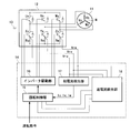
- FIG. 1 shows the configuration of a conventional motor control device of this type, in which 11 is a motor, 12 is an inverter, 13 is a DC power supply, and 14 is a controller incorporating a microcomputer.
- the controller 14 includes a rotation control unit 15, an inverter drive unit 16, a phase current detection unit 17, and an overcurrent detection unit 18.
- the motor 11 comprises a three-phase DC brushless motor, a stator (not shown) including three-phase coils (U-phase coil Uc, V-phase coil Vc and W-phase coil Wc), and a rotor (not shown) including a permanent magnet.
- the U-phase coil Uc, the V-phase coil Vc, and the W-phase coil Wc are connected in a star shape around a neutral point N as shown in the drawing, or are connected in a delta shape.
- the inverter 12 is composed of a three-phase bipolar drive type inverter, and is composed of a three-phase switching element corresponding to the three-phase coil of the motor 11, more specifically, six switching elements (upper phase switching elements Us, Vs and Ws, lower phase switching elements Xs, Ys, and Zs), and shunt resistors Ru, Rv, and Rw.
- Each shunt resistor Ru, Rv, and Rw is for detecting a voltage that is an alternative to the current flowing through each phase of the inverter 12.
- the upper phase switching element Us, the lower phase switching element Xs, and the shunt resistor Ru are arranged in series and both ends thereof are connected to the DC power source 13, and the upper phase switching element Vs, the lower phase switching element Ys, and the shunt resistor Rv are in series.
- the upper phase switching element Ws, the lower phase switching element Zs, and the shunt resistor Rw are arranged in series, and both ends thereof are connected to the DC power source 13.
- the emitter side of the upper phase switching element Us is connected to the U phase coil Uc of the motor 11, the emitter side of the upper phase switching element Vs is connected to the V phase coil Vc of the motor 11, and the emitter side of the upper phase switching element Ws. Is connected to the V-phase coil Wc of the motor 11. Furthermore, the gates of the upper-phase switching elements Us, Vs, and Ws and the gates of the lower-phase switching elements Xs, Ys, and Zs are connected to the inverter drive unit 16, respectively.
- the lower phase switching element Xs side of the shunt resistor Ru is connected to the phase current detection unit 17 and the overcurrent detection unit 18, and the lower phase switching element Ys side of the shunt resistor Rv is connected to the phase current detection unit 17 and the overcurrent detection unit.
- the lower phase switching element Zs side of the shunt resistor Rw is connected to the phase current detection unit 17 and the overcurrent detection unit 18.
- the rotation control unit 15 sends a control signal for rotating or stopping the motor 11 at a predetermined rotational speed to the inverter drive unit 16 based on an operation command from an operation unit (not shown).
- the inverter drive unit 16 Based on the control signal from the rotation control unit 15, the inverter drive unit 16 turns on / off each switching element to the gate of the upper phase switching elements Us, Vs, and Ws of the inverter 12 and the gate of the lower phase switching elements Xs, Ys, and Zs. A drive signal for sending is sent.
- the upper phase switching elements Us, Vs, and Ws of the inverter 12 and the lower phase switching elements Xs, Ys, and Zs are turned on and off in a predetermined pattern by a drive signal from the inverter drive unit 16, and energization based on the on / off pattern, specifically, sine Wave energization (180-degree energization) or rectangular wave energization (120-degree energization) is performed on the U-phase coil Uc, V-phase coil Vc, and W-phase coil Wc of the motor 11.
- the phase current detection unit 17 is based on the voltages Vru, Vrv, and Vrw detected by the shunt resistors Ru, Rv, and Rw of the inverter 12, and the U-phase coil Uc, the V-phase coil Vc, and the W-phase coil Wc of the motor 11.
- Current U-phase current Iu, V-phase current Iv and W-phase current Iw
- the rotation control unit 15 detects the rotor position of the motor 11 based on detection signals (U-phase current Iu, V-phase current Iv, and W-phase current Iw) from the phase current detection unit 17.
- the overcurrent detection unit 18 uses a comparator to compare the voltages Vru, Vrv, and Vrw (including the amplified case) detected by the shunt resistors Ru, Rv, and Rw of the inverter 12 and the reference voltage Vref for overcurrent determination.
- the comparison results are sent to the rotation control unit 15 as detection signals.
- the rotation control unit 15 determines the presence / absence of an overcurrent based on a detection signal (comparison result) from the overcurrent detection unit 18, and when determining that there is an overcurrent, the rotation control unit 15 outputs a control signal for stopping the energization by the inverter 12. To protect the inverter 12.
- the overcurrent protection function performed by the rotation control unit 15 of the motor control device is based on the premise that the overcurrent detection unit 18 is operating normally.
- the overcurrent protection function is not executed even if an overcurrent occurs, and the overcurrent causes various problems such as breakage of the switching element of the inverter 12, disconnection of the power fuse, and interruption of the power breaker.
- the present invention compares a voltage detection means for detecting a voltage that substitutes for a current flowing in a motor inverter, and a detection voltage from the voltage detection means and a reference voltage for overcurrent determination.
- An overcurrent detection means for determining whether or not an overcurrent is detected based on a detection signal from the overcurrent detection means, wherein the reference is set when the motor is not rotating.
- An overcurrent inspection means for sending an inspection voltage higher than the voltage to the overcurrent detection means instead of the detection voltage, and an overcurrent when the inspection voltage from the overcurrent inspection means is judged as no overcurrent in the overcurrent determination means
- An abnormality diagnosing means for determining that an abnormality has occurred in the detecting means.
- an overcurrent inspection unit that sends an inspection voltage higher than the reference voltage to the overcurrent detection unit instead of the detection voltage, and an inspection from the overcurrent inspection unit
- the overcurrent detection means determines that there is no overcurrent
- the overcurrent detection means has an abnormality diagnosis means that determines that an abnormality has occurred. This can be diagnosed accurately even if Therefore, problems such as inverter switching element breakage, power supply fuse disconnection and power supply breaker interruption due to abnormalities in the overcurrent detection means, as well as elucidation of the cause of problems and recovery measures for those problems Therefore, it is possible to surely avoid a great deal of time and cost.
- FIG. 1 is a block diagram of a conventional motor control device.
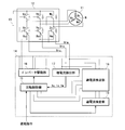
- FIG. 2 is a block diagram of a motor control device to which the present invention is applied.
- FIG. 3 is a detailed view of the overcurrent detection unit and the overcurrent inspection unit shown in FIG.
- FIG. 4 is a diagram showing an abnormality diagnosis flow executed by the motor control device shown in FIG.
- FIG. 5 is a diagram showing another abnormality diagnosis flow executed by the motor control device shown in FIG.
- FIG. 2 shows a motor control apparatus to which the present invention is applied.
- 11 is a motor
- 12 is an inverter
- 13 is a DC power supply
- 14 is a controller incorporating a microcomputer.
- the controller 14 includes a rotation control unit 15, an inverter drive unit 16, a phase current detection unit 17, an overcurrent detection unit 18, and an overcurrent inspection unit 19.
- the motor control device shown in FIG. 2 differs from the conventional motor control device shown in FIG. -The point provided with the overcurrent test
- the overcurrent detector 18 has three comparators CP1, CP2 and CP3 as shown in FIG.
- the voltage Vru detected by the shunt resistor Ru is input to the input terminal of the comparator CP1 via the resistor
- the voltage Vrv detected by the shunt resistor Rv is input to the input terminal of the comparator CP2 via the resistor.
- the voltage Vrw detected by the shunt resistor Rw is input to the input terminal of the comparator CP3 through the resistor. That is, the overcurrent detection unit 18 compares the voltages Vru, Vrv, and Vrw (including the amplified case) with the reference voltage Vref for overcurrent determination using the comparators CP1, CP2, and CP3, and compares the comparison results.
- the detection signal is sent to the rotation control unit 15.
- the overcurrent inspection unit 19 includes three inspection devices 19a, 19b, and 19c including a first switch s1, a second switch s2, a first resistor r1, and a second resistor r2. ing.
- a switching element such as a transistor that can be opened and closed based on a control signal from the rotation control unit 15 is used for the first switch s1 and the second switch s2 of each of the inspection devices 19a, 19b, and 19c.
- the first switch s1 and the first resistor r1 of each of the testers 19a, 19b, and 19c are arranged in series, and one end thereof is connected to the first power source V1, and the second switch s2 and the first resistor r2 are connected.
- the output side of the tester 19a is connected to the input terminal side of the comparator CP1 of the overcurrent detector 18, and the output side of the tester 19b is connected to the input terminal side of the comparator CP2 of the overcurrent detector 18.
- the output side of 19c is connected to the input terminal side of the comparator CP3 of the overcurrent detection unit 18.
- the overcurrent inspection unit 19 closes only the first switch s1 of each of the inspection devices 19a, 19b, and 19c, thereby using the inspection voltage Vt1 lower than the reference voltage Vref for overcurrent determination as an inspection signal.
- the data can be sent to the input terminals of the comparators CP1, CP2 and CP3 of the unit 18.
- the voltage values of the first power supply V1 and the second power supply V2 and the first resistance so that a test voltage Vt1 lower than the reference voltage Vref for overcurrent determination and a test voltage Vt2 equal to or higher than the reference voltage Vref are obtained.
- the resistance values of the resistor r1 and the second resistor r2 are selected. For example, when the first power supply V1 and the second power supply V2 are set to the same voltage value, and the first resistor r1 and the second resistor r2 are set to the same resistance value, the test voltage Vt2 is approximately twice the test voltage Vt1. Value.
- FIG. 4 shows a flow when diagnosing an abnormality of the overcurrent detection unit 18 by using the overcurrent inspection unit 19, and the abnormality diagnosis flow is performed when the motor 11 is not rotating.
- a control signal for closing only the first switch s1 of each of the inspection devices 19a, 19b and 19c is sent from the rotation control unit 15 to the overcurrent inspection unit 19 at the above timing, and each inspection device 19a, Only the first switches s1 of 19b and 19c are closed (see step ST11 in FIG. 4).
- the test voltage Vt1 is sent as a test signal from the overcurrent test unit 19 to the input terminals of the comparators CP1, CP2, and CP3 of the overcurrent detection unit 18. Is done.
- the overcurrent detection unit 18 uses the inspection voltage Vt1 from the overcurrent inspection unit 19 and the overcurrent determination for the overcurrent determination for the voltages Vru, Vrv, and Vrw detected by the shunt resistors Ru, Rv, and Rw.
- the reference voltage Vref is compared with each of the comparators CP1, CP2, and CP3, and the comparison result is sent to the rotation control unit 15 as a detection signal.
- the rotation control unit 15 determines the presence or absence of overcurrent from the detection signal (comparison result) from the overcurrent detection unit 18 (see step ST12 in FIG. 4).
- step ST12 since the inspection voltage Vt1 ⁇ the reference voltage Vref, when the overcurrent detector 18 is operating normally, it is determined in step ST12 that the inspection voltage Vt1 has no overcurrent. However, when it is determined in step ST12 that there is an overcurrent, it is considered that an abnormality such as a failure has occurred in the overcurrent detection unit 18, and the abnormality is notified by lighting an alarm lamp or generating an alarm sound (FIG. 4). (See step ST13). The user performs measures such as disconnecting the main power supply based on the abnormality notification.
- the rotation control unit 15 subsequently controls the overcurrent inspection unit 19 to close both the first switch s1 and the second switch s2 of each of the inspection devices 19a, 19b, and 19c.
- a signal is sent, and both the first switch s1 and the second switch s2 of each tester 19a, 19b, and 19c are closed (see step ST14 in FIG. 4).
- both the first switch s1 and the second switch s2 of the testers 19a, 19b and 19c are closed, the test voltage is applied from the overcurrent test unit 19 to the input terminals of the comparators CP1, CP2 and CP3 of the overcurrent detection unit 18. Vt2 is transmitted as an inspection signal.
- the overcurrent detection unit 18 uses the inspection voltage Vt2 from the overcurrent inspection unit 19 and the overcurrent determination for the overcurrent determination with respect to the voltages Vru, Vrv, and Vrw detected by the shunt resistors Ru, Rv, and Rw.
- the reference voltage Vref is compared with each of the comparators CP1, CP2, and CP3, and the comparison result is sent to the rotation control unit 15 as a detection signal.
- the rotation control unit 15 determines the presence or absence of overcurrent from the detection signal (comparison result) from the overcurrent detection unit 18 (see step ST15 in FIG. 4).
- step ST15 since the inspection voltage Vt2 ⁇ the reference voltage Vref, when the overcurrent detector 18 is operating normally, it is determined in step ST15 that the inspection voltage Vt2 is overcurrent. However, when it is determined in step ST15 that there is no overcurrent, it is considered that an abnormality such as a failure has occurred in the overcurrent detector 18, and the abnormality is notified by lighting an alarm lamp, generating an alarm sound, or the like (FIG. 4). (See step ST16). The user performs measures such as disconnecting the main power supply based on the abnormality notification.
- step ST15 When it is determined in step ST15 that there is an overcurrent, the rotation control unit 15 subsequently controls the overcurrent inspection unit 19 to open both the first switch s1 and the second switch s2 of each of the inspection devices 19a, 19b, and 19c. A signal is transmitted, and the first switch s1 and the second switch s2 of each of the inspection devices 19a, 19b and 19c are opened (see step ST17 in FIG. 4).
- such abnormality diagnosis is performed when the motor 11 is a motor used as a driving power source in a hybrid car, an electric vehicle, or the like, or a motor used as a compressor power source in an automobile air conditioner.
- Very useful That is, in any case, if the above-mentioned problems occur due to the abnormality of the overcurrent detection unit 18, in the former case, in addition to suddenly being unable to travel by motor power, an accident occurs during traveling by motor power. In the latter case, the air conditioning is impossible, which not only makes the driver uncomfortable but also may cause worsening of the medical condition for the unhealthy person. If the diagnosis can be performed, the above-mentioned fears can be eliminated, and the user's sense of security and reliability can be improved.
- the motor control device shown in FIG. 2 incorporates shunt resistors Ru, Rv and Rw in the inverter 12 for detecting a voltage as an alternative to the current flowing in each phase of the inverter 12.
- the desired overcurrent cannot be detected when the motor 11 is rotating even if the overcurrent detector 18 is operating normally. . That is, in order to accurately detect the desired overcurrent, it is desirable to diagnose whether an abnormality such as a failure has occurred in the shunt resistors Ru, Rv, and Rw when the motor 11 is rotating.
- FIG. 5 shows a flow when the abnormality diagnosis of the shunt resistors Ru, Rv and Rw is performed.
- the abnormality diagnosis flow is such that the synchronous motor 11 rotates and a current flows through each of the shunt resistors Ru, Rv and Rw. When it is executed.
- the rotation control unit 15 determines whether or not the sum of the U-phase current Iu, the V-phase current Iv, and the W-phase current Iw detected by the phase current detection unit 17 is zero (FIG. 5). (See step ST21).
- such abnormality diagnosis is performed when the motor 11 is a motor used as a driving power source in a hybrid car, an electric vehicle, or the like, or a motor used as a compressor power source in an automobile air conditioner.
- Very useful That is, in any case, if the above-mentioned problems occur due to the abnormality of the overcurrent detection unit 18, in the former case, in addition to suddenly being unable to travel by motor power, an accident occurs during traveling by motor power. In the latter case, the air conditioning is impossible, which not only makes the driver uncomfortable but also may cause worsening of the medical condition for the unhealthy person. If the diagnosis can be performed, the above-mentioned fears can be eliminated, and the user's sense of security and reliability can be further improved.
- the shunt resistors Ru, Rv, and Rw of the inverter 12 function as “voltage detection means” in the claims
- the overcurrent detection unit 18 is “overcurrent detection means” in the claims.
- the processing relating to overcurrent determination in the rotation control unit 15 functions as “overcurrent determination unit” in the claims
- the overcurrent inspection unit 19 performs “overcurrent inspection unit” and “second overcurrent detection” in the claims.
- the function relating to the abnormality diagnosis in the rotation control unit 15 functions as the “abnormality diagnostic means” and the “second abnormality diagnostic means”.
- the flow of performing the abnormality diagnosis based on the inspection voltage Vt1 and the abnormality diagnosis based on the inspection voltage Vt2 is illustrated.
- the inspection voltage Even if only the abnormality diagnosis based on the inspection voltage Vt2 is performed without performing the abnormality diagnosis based on Vt1, the intended purpose can be sufficiently achieved.
- abnormality diagnosis based on the inspection voltage Vt1 is performed together, it is needless to say that abnormality diagnosis capability can be enhanced.
- the motor control device including the three-phase bipolar brushless motor inverter for the three-phase DC brushless motor as the inverter 12 is illustrated.
- the motor control device includes the motor inverter, for example, A motor control device including an inverter (including a unipolar drive system) for DC brushless motors other than three phases, a motor control device including an inverter for one or more phases of synchronous motors different from the DC brushless motor, Even in a motor control device provided with an inverter for induction motors of a phase or higher, or a motor control device provided with an inverter for other motors, the present invention can be applied to obtain the same operation and effect as described above. it can.
- the motor control device in which the shunt resistors Ru, Rv, and Rw for detecting the voltage that substitutes for the current flowing in each phase of the inverter 12 is incorporated in the inverter 12 is exemplified.
- a shunt resistor Ru, Rv can be used as long as it is a motor control device having a voltage detection means for detecting a voltage that is a substitute for a current flowing through an inverter (including other types of inverters as described in the previous paragraph).
- the motor control device in which Rw and Rw are arranged outside the inverter 12 and a sensor (for example, a sensor using a current transformer or a hall element) that performs the same role instead of the shunt resistors Ru, Rv, and Rw are located at the same position. Or even if it is a motor control apparatus arrange
- the present invention is suitable as a motor control device provided with an overcurrent detection means for an inverter.
- SYMBOLS 11 Motor, Uc ... U phase coil, Vc ... V phase coil, Wc ... W phase coil, 12 ... Inverter, Us, Vs, Ws ... Upper phase switching element, Xs, Ys, Zs ... Lower phase switching element, Ru, Rv, Rw ... shunt resistors, 13 ... DC power supply, 14 ... controller, 15 ... rotation control unit, 16 ... inverter drive unit, 17 ... phase current detection unit, 18 ... overcurrent detection unit, 19 ... overcurrent inspection unit.
Landscapes
- Engineering & Computer Science (AREA)
- Power Engineering (AREA)
- Control Of Motors That Do Not Use Commutators (AREA)
- Control Of Ac Motors In General (AREA)
- Inverter Devices (AREA)
Abstract
Description
・過電流検出部18の異常を診断する際に用いられる過電流検査部19を備える点
・過電流検査部19を利用して過電流検出部18の異常を診断する機能を備える点
にある。他は図1に示した従来のモータ制御装置と同じであるため、同一符号を用いてその説明を省略する。
Claims (6)
- モータ用のインバータに流れる電流の代替となる電圧を検出する電圧検出手段と、該電圧検出手段からの検出電圧と過電流判断用の基準電圧とを比較する過電流検出手段と、該過電流検出手段からの検出信号によって過電流の有無を判断する過電流判断手段と、を具備したモータ制御装置であって、
モータが回転していないときに前記基準電圧以上の検査電圧を前記検出電圧の代わりに過電流検出手段に送出する過電流検査手段と、
過電流検査手段からの検査電圧が過電流判断手段において過電流無しと判断されたときに過電流検出手段に異常が生じていると判断する異常診断手段と、を備える。 - 請求項1に記載のモータ制御装置において、
モータが回転していないときに前記基準電圧よりも低い第2の検査電圧を前記検出電圧の代わりに過電流検出手段に送出する第2の過電流検査手段と、
第2の過電流検査手段からの第2の検査電圧が過電流判断手段において過電流有りと判断されたときに過電流検出手段に異常が生じていると判断する第2の異常診断手段と、さらにを備える。 - 請求項1または2に記載のモータ制御装置において、
異常診断手段または第2の異常診断手段において過電流検出手段に異常が生じていると判断されたときに該異常を報知する異常報知手段を、さらに備える。 - 請求項1~3の何れか1項に記載のモータ制御装置において、
モータはステータに複数相のコイルを有する同期モータであり、インバータは同期モータの複数相のコイルに対応した複数相のスイッチング素子を有するインバータである。 - 請求項4に記載のモータ制御装置において、
電圧検出手段は、インバータの各相に流れる電流の代替となる電圧を検出するためのシャント抵抗器から成る。 - 請求項5に記載のモータ制御装置において、
同期モータが回転しているときに該同期モータの複数相のコイルそれぞれに流れる電流を検出する電流検出手段と、
電流検出手段からの検出電流の和が零でないときにシャント抵抗器に異常が生じていると判断する第3の異常診断手段と、をさらに備える。
Priority Applications (3)
| Application Number | Priority Date | Filing Date | Title |
|---|---|---|---|
| US13/322,247 US9024555B2 (en) | 2009-05-27 | 2010-05-27 | Motor control device |
| EP10780288.6A EP2432112B1 (en) | 2009-05-27 | 2010-05-27 | Motor control device |
| CN201080022361.6A CN102428640B (zh) | 2009-05-27 | 2010-05-27 | 电动机控制装置 |
Applications Claiming Priority (2)
| Application Number | Priority Date | Filing Date | Title |
|---|---|---|---|
| JP2009127749A JP5537837B2 (ja) | 2009-05-27 | 2009-05-27 | モータ制御装置 |
| JP2009-127749 | 2009-05-27 |
Publications (1)
| Publication Number | Publication Date |
|---|---|
| WO2010137328A1 true WO2010137328A1 (ja) | 2010-12-02 |
Family
ID=43222454
Family Applications (1)
| Application Number | Title | Priority Date | Filing Date |
|---|---|---|---|
| PCT/JP2010/003564 Ceased WO2010137328A1 (ja) | 2009-05-27 | 2010-05-27 | モータ制御装置 |
Country Status (5)
| Country | Link |
|---|---|
| US (1) | US9024555B2 (ja) |
| EP (1) | EP2432112B1 (ja) |
| JP (1) | JP5537837B2 (ja) |
| CN (1) | CN102428640B (ja) |
| WO (1) | WO2010137328A1 (ja) |
Cited By (3)
| Publication number | Priority date | Publication date | Assignee | Title |
|---|---|---|---|---|
| CN103078520A (zh) * | 2011-10-26 | 2013-05-01 | 乐星产电(无锡)有限公司 | 变频器装置以及该变频器装置的过电流保护方法 |
| CN103959632A (zh) * | 2011-11-21 | 2014-07-30 | 三电有限公司 | 逆变器系统的故障检测装置 |
| WO2020116374A1 (ja) * | 2018-12-04 | 2020-06-11 | 日本電産株式会社 | 過電流検出装置、及びモータユニット |
Families Citing this family (22)
| Publication number | Priority date | Publication date | Assignee | Title |
|---|---|---|---|---|
| JP5880967B2 (ja) * | 2012-09-28 | 2016-03-09 | 株式会社デンソー | 交流電動機の制御装置 |
| JP6201319B2 (ja) | 2013-01-15 | 2017-09-27 | 住友電気工業株式会社 | 変換装置、故障判定方法及び制御プログラム |
| KR101707706B1 (ko) | 2013-07-03 | 2017-02-16 | 엘에스산전 주식회사 | 보호 장치 및 그의 동작 검증 방법 |
| JP2015104240A (ja) * | 2013-11-26 | 2015-06-04 | 株式会社デンソー | 回転電機駆動装置、および、これを用いた電動パワーステアリング装置。 |
| JP5939235B2 (ja) * | 2013-11-26 | 2016-06-22 | 株式会社デンソー | 回転電機駆動装置、および、これを用いた電動パワーステアリング装置 |
| JP6225371B2 (ja) * | 2013-12-24 | 2017-11-08 | 日本電産テクノモータ株式会社 | モータ駆動装置 |
| JP6291352B2 (ja) * | 2014-05-26 | 2018-03-14 | 日本電産サンキョー株式会社 | モータ制御装置およびモータ制御方法 |
| JP6266451B2 (ja) * | 2014-06-30 | 2018-01-24 | 日立オートモティブシステムズ株式会社 | 駆動回路装置 |
| CN106575925B (zh) * | 2014-08-04 | 2018-12-04 | 日立汽车系统株式会社 | 电力转换装置 |
| WO2016038683A1 (ja) * | 2014-09-09 | 2016-03-17 | 三菱電機株式会社 | 多相交流モータ駆動用インバータ装置 |
| KR101993195B1 (ko) | 2015-04-09 | 2019-06-26 | 엘에스산전 주식회사 | 인버터의 지락 검출 방법 |
| JP6506644B2 (ja) * | 2015-07-09 | 2019-04-24 | 日立オートモティブシステムズ株式会社 | 駆動装置 |
| WO2017030020A1 (ja) * | 2015-08-19 | 2017-02-23 | 日本精工株式会社 | 電子制御装置及びそれを搭載した電動パワーステアリング装置 |
| JP6897025B2 (ja) * | 2016-08-08 | 2021-06-30 | 株式会社アイシン | モータ制御装置 |
| US10322748B2 (en) * | 2016-09-23 | 2019-06-18 | Jtekt Corporation | Motor controller and steering device |
| EP3618260B1 (en) * | 2017-04-27 | 2023-12-13 | Mitsubishi Electric Corporation | Motor control device and air conditioner |
| JP7146688B2 (ja) * | 2019-04-23 | 2022-10-04 | ルネサスエレクトロニクス株式会社 | 駆動装置、及び、電力供給システム |
| JP7131510B2 (ja) * | 2019-08-26 | 2022-09-06 | 株式会社デンソー | モータ制御装置 |
| JP7306237B2 (ja) * | 2019-11-22 | 2023-07-11 | 株式会社デンソー | 電源システム |
| JP7497269B2 (ja) * | 2020-10-26 | 2024-06-10 | 株式会社マキタ | 電動作業機 |
| US12578387B2 (en) | 2024-01-04 | 2026-03-17 | Hitachi Astemo, Ltd. | Systems and methods for fault detection, diagnosis, and recovery in an electromechanical actuator |
| WO2025163710A1 (ja) * | 2024-01-29 | 2025-08-07 | Astemo株式会社 | 過電流検出回路及び過電流検出方法 |
Citations (6)
| Publication number | Priority date | Publication date | Assignee | Title |
|---|---|---|---|---|
| JPH0829470A (ja) * | 1994-07-14 | 1996-02-02 | Yaskawa Electric Corp | 電流検出器の故障検出方法 |
| JP2001320894A (ja) * | 2000-05-08 | 2001-11-16 | Matsushita Electric Ind Co Ltd | モータ駆動装置 |
| JP2002325353A (ja) | 2001-04-23 | 2002-11-08 | Sanyo Electric Co Ltd | インバータ保護装置 |
| JP2004173348A (ja) * | 2002-11-18 | 2004-06-17 | Calsonic Kansei Corp | 電動モータ制御装置 |
| WO2005004319A1 (ja) * | 2003-07-02 | 2005-01-13 | Kabushiki Kaisha Yaskawa Denki | インバータの出荷自動試験装置およびその試験方法 |
| JP2006160030A (ja) * | 2004-12-06 | 2006-06-22 | Nsk Ltd | 電動パワーステアリング装置 |
Family Cites Families (9)
| Publication number | Priority date | Publication date | Assignee | Title |
|---|---|---|---|---|
| JPH1169865A (ja) * | 1997-08-26 | 1999-03-09 | Toyota Motor Corp | 電動モータ駆動装置 |
| JP2001157487A (ja) * | 1999-11-26 | 2001-06-08 | Nissan Motor Co Ltd | 回転電機の制御装置 |
| JP2001238480A (ja) * | 2000-02-21 | 2001-08-31 | Matsushita Electric Ind Co Ltd | インバータ装置およびこれを使用した電気洗濯機 |
| JP2002291284A (ja) * | 2001-03-26 | 2002-10-04 | Toshiba Kyaria Kk | 電動機の電流検出方法及び制御装置 |
| US6577087B2 (en) * | 2001-05-10 | 2003-06-10 | Ut-Battelle, Llc | Multilevel DC link inverter |
| US6737828B2 (en) * | 2001-07-19 | 2004-05-18 | Matsushita Electric Industrial Co., Ltd. | Washing machine motor drive device |
| JP4682727B2 (ja) * | 2005-07-13 | 2011-05-11 | パナソニック株式会社 | モータ駆動装置 |
| JP4643419B2 (ja) * | 2005-11-08 | 2011-03-02 | 矢崎総業株式会社 | 自己診断機能を備えた負荷駆動装置 |
| JP2007333685A (ja) * | 2006-06-19 | 2007-12-27 | Matsushita Electric Ind Co Ltd | 故障検査装置 |
-
2009
- 2009-05-27 JP JP2009127749A patent/JP5537837B2/ja active Active
-
2010
- 2010-05-27 US US13/322,247 patent/US9024555B2/en active Active
- 2010-05-27 WO PCT/JP2010/003564 patent/WO2010137328A1/ja not_active Ceased
- 2010-05-27 EP EP10780288.6A patent/EP2432112B1/en active Active
- 2010-05-27 CN CN201080022361.6A patent/CN102428640B/zh active Active
Patent Citations (6)
| Publication number | Priority date | Publication date | Assignee | Title |
|---|---|---|---|---|
| JPH0829470A (ja) * | 1994-07-14 | 1996-02-02 | Yaskawa Electric Corp | 電流検出器の故障検出方法 |
| JP2001320894A (ja) * | 2000-05-08 | 2001-11-16 | Matsushita Electric Ind Co Ltd | モータ駆動装置 |
| JP2002325353A (ja) | 2001-04-23 | 2002-11-08 | Sanyo Electric Co Ltd | インバータ保護装置 |
| JP2004173348A (ja) * | 2002-11-18 | 2004-06-17 | Calsonic Kansei Corp | 電動モータ制御装置 |
| WO2005004319A1 (ja) * | 2003-07-02 | 2005-01-13 | Kabushiki Kaisha Yaskawa Denki | インバータの出荷自動試験装置およびその試験方法 |
| JP2006160030A (ja) * | 2004-12-06 | 2006-06-22 | Nsk Ltd | 電動パワーステアリング装置 |
Non-Patent Citations (1)
| Title |
|---|
| See also references of EP2432112A4 |
Cited By (5)
| Publication number | Priority date | Publication date | Assignee | Title |
|---|---|---|---|---|
| CN103078520A (zh) * | 2011-10-26 | 2013-05-01 | 乐星产电(无锡)有限公司 | 变频器装置以及该变频器装置的过电流保护方法 |
| CN103959632A (zh) * | 2011-11-21 | 2014-07-30 | 三电有限公司 | 逆变器系统的故障检测装置 |
| US9360515B2 (en) | 2011-11-21 | 2016-06-07 | Sanden Corporation | Fault detection device for inverter system |
| CN103959632B (zh) * | 2011-11-21 | 2016-09-28 | 三电控股株式会社 | 逆变器系统的故障检测装置 |
| WO2020116374A1 (ja) * | 2018-12-04 | 2020-06-11 | 日本電産株式会社 | 過電流検出装置、及びモータユニット |
Also Published As
| Publication number | Publication date |
|---|---|
| EP2432112A4 (en) | 2014-10-22 |
| CN102428640B (zh) | 2015-09-09 |
| JP5537837B2 (ja) | 2014-07-02 |
| EP2432112B1 (en) | 2016-07-20 |
| CN102428640A (zh) | 2012-04-25 |
| US20120074885A1 (en) | 2012-03-29 |
| EP2432112A1 (en) | 2012-03-21 |
| JP2010279125A (ja) | 2010-12-09 |
| US9024555B2 (en) | 2015-05-05 |
Similar Documents
| Publication | Publication Date | Title |
|---|---|---|
| JP5537837B2 (ja) | モータ制御装置 | |
| CN101595633B (zh) | 电动机控制装置 | |
| JP4333751B2 (ja) | ブラシレスモータの駆動装置 | |
| CN106063121B (zh) | 电机控制装置及电机的控制方法 | |
| JP6157752B2 (ja) | 多相交流モータ駆動用インバータ装置 | |
| US8536877B2 (en) | Power cable breaking detection method of motor | |
| US11472472B2 (en) | Power conversion device, motor module, and electric power steering device | |
| US10673364B2 (en) | Motor control method, motor drive system, and electric power steering system | |
| US10071762B2 (en) | Detection and mitigation of inverter errors in steering system motors | |
| EP2037566A1 (en) | Multi-phase AC motor driving device | |
| US20200186075A1 (en) | Power conversion device, motor module, and electric power steering device | |
| CN106031021A (zh) | 电动机的驱动控制装置及驱动控制方法 | |
| CN110417314B (zh) | 马达控制装置及电动助力转向装置 | |
| CN109951135B (zh) | 电力控制单元 | |
| US20200028463A1 (en) | Motor driving device and steering system | |
| JPWO2016021329A1 (ja) | 電力変換装置 | |
| JP6911570B2 (ja) | 検出装置 | |
| JP5169187B2 (ja) | インバータの短絡素子判定装置 | |
| JP2000125586A (ja) | 故障診断方法および装置 | |
| JP3684940B2 (ja) | 異常検出システム | |
| JP2009254083A (ja) | モータ出力回路の異常検出装置 | |
| KR102159110B1 (ko) | 차량용 모터 구동장치 | |
| JP2019041522A (ja) | モータ駆動制御装置及びモータの駆動制御方法 | |
| JP2018050424A (ja) | 2軸型インバータ装置およびその逐次監視切替方法 | |
| JP2007110815A (ja) | 電力変換装置 |
Legal Events
| Date | Code | Title | Description |
|---|---|---|---|
| WWE | Wipo information: entry into national phase |
Ref document number: 201080022361.6 Country of ref document: CN |
|
| 121 | Ep: the epo has been informed by wipo that ep was designated in this application |
Ref document number: 10780288 Country of ref document: EP Kind code of ref document: A1 |
|
| WWE | Wipo information: entry into national phase |
Ref document number: 13322247 Country of ref document: US |
|
| NENP | Non-entry into the national phase |
Ref country code: DE |
|
| REEP | Request for entry into the european phase |
Ref document number: 2010780288 Country of ref document: EP |
|
| WWE | Wipo information: entry into national phase |
Ref document number: 2010780288 Country of ref document: EP |