WO2010137364A1 - 校正目標検出装置と、校正目標を検出する校正目標検出方法と、校正目標検出装置のためのプログラム - Google Patents
校正目標検出装置と、校正目標を検出する校正目標検出方法と、校正目標検出装置のためのプログラム Download PDFInfo
- Publication number
- WO2010137364A1 WO2010137364A1 PCT/JP2010/052448 JP2010052448W WO2010137364A1 WO 2010137364 A1 WO2010137364 A1 WO 2010137364A1 JP 2010052448 W JP2010052448 W JP 2010052448W WO 2010137364 A1 WO2010137364 A1 WO 2010137364A1
- Authority
- WO
- WIPO (PCT)
- Prior art keywords
- calibration target
- photometric
- profile
- area
- luminance
- Prior art date
- Legal status (The legal status is an assumption and is not a legal conclusion. Google has not performed a legal analysis and makes no representation as to the accuracy of the status listed.)
- Ceased
Links
Images






Classifications
-
- H—ELECTRICITY
- H04—ELECTRIC COMMUNICATION TECHNIQUE
- H04N—PICTORIAL COMMUNICATION, e.g. TELEVISION
- H04N17/00—Diagnosis, testing or measuring for television systems or their details
- H04N17/002—Diagnosis, testing or measuring for television systems or their details for television cameras
-
- G—PHYSICS
- G06—COMPUTING OR CALCULATING; COUNTING
- G06T—IMAGE DATA PROCESSING OR GENERATION, IN GENERAL
- G06T7/00—Image analysis
- G06T7/80—Analysis of captured images to determine intrinsic or extrinsic camera parameters, i.e. camera calibration
-
- G—PHYSICS
- G06—COMPUTING OR CALCULATING; COUNTING
- G06V—IMAGE OR VIDEO RECOGNITION OR UNDERSTANDING
- G06V20/00—Scenes; Scene-specific elements
- G06V20/50—Context or environment of the image
- G06V20/56—Context or environment of the image exterior to a vehicle by using sensors mounted on the vehicle
-
- H—ELECTRICITY
- H04—ELECTRIC COMMUNICATION TECHNIQUE
- H04N—PICTORIAL COMMUNICATION, e.g. TELEVISION
- H04N23/00—Cameras or camera modules comprising electronic image sensors; Control thereof
- H04N23/70—Circuitry for compensating brightness variation in the scene
- H04N23/71—Circuitry for evaluating the brightness variation
-
- H—ELECTRICITY
- H04—ELECTRIC COMMUNICATION TECHNIQUE
- H04N—PICTORIAL COMMUNICATION, e.g. TELEVISION
- H04N23/00—Cameras or camera modules comprising electronic image sensors; Control thereof
- H04N23/70—Circuitry for compensating brightness variation in the scene
- H04N23/73—Circuitry for compensating brightness variation in the scene by influencing the exposure time
-
- G—PHYSICS
- G06—COMPUTING OR CALCULATING; COUNTING
- G06T—IMAGE DATA PROCESSING OR GENERATION, IN GENERAL
- G06T2207/00—Indexing scheme for image analysis or image enhancement
- G06T2207/20—Special algorithmic details
- G06T2207/20068—Projection on vertical or horizontal image axis
-
- G—PHYSICS
- G06—COMPUTING OR CALCULATING; COUNTING
- G06T—IMAGE DATA PROCESSING OR GENERATION, IN GENERAL
- G06T2207/00—Indexing scheme for image analysis or image enhancement
- G06T2207/30—Subject of image; Context of image processing
- G06T2207/30204—Marker
-
- G—PHYSICS
- G06—COMPUTING OR CALCULATING; COUNTING
- G06T—IMAGE DATA PROCESSING OR GENERATION, IN GENERAL
- G06T2207/00—Indexing scheme for image analysis or image enhancement
- G06T2207/30—Subject of image; Context of image processing
- G06T2207/30248—Vehicle exterior or interior
- G06T2207/30252—Vehicle exterior; Vicinity of vehicle
Definitions
- the present invention relates to a calibration target detection device, a calibration target detection method for detecting a calibration target, and a program for the calibration target detection device.
- Patent Document 1 discloses an optical axis deviation detection device that detects an optical axis deviation of an in-vehicle camera mounted on a vehicle.
- the optical axis deviation detection device detects a detection reference used when detecting an optical axis deviation using a template matching process. More specifically, the template matching process is repeatedly performed while shifting the detection reference template image from the center of the captured image including the target image of the in-vehicle camera. Then, the position of the image that matches the template image on the captured image is specified as the position of the target image.
- an object of the present invention is to provide a calibration target detection device, a calibration target detection method for detecting a calibration target, and a calibration target detection device that can be realized at low cost without an increase in storage capacity. To provide a program.
- the calibration target detection apparatus includes a photometric area setting unit for setting a long photometric area, a detection unit for detecting photometric information in the photometric area, and a predetermined configuration.
- a long photometric area having one direction as a long direction is scanned along another direction orthogonal to the one direction to generate a first profile indicating a change in photometric information in the other direction, and the other
- a profile generating unit that generates a second profile indicating a change in photometric information in the one direction by scanning a long photometric area whose direction is a long direction along the one direction, the first profile, Based on the feature points of the second profile, the position of the calibration target used for the calibration of the in-vehicle camera included in the captured image acquired by the in-vehicle camera or the position of the predetermined part of the calibration target is calculated.
- it comprises a location calculating unit.
- a general in-vehicle camera has a function of setting a photometric area and detecting photometric information of the set photometric area. For this reason, according to this feature configuration, the position of the calibration target or the position of the predetermined portion of the calibration target is specified based on the feature points of the first profile and the second profile without providing a new function unit. It becomes possible. Therefore, it is possible to realize a calibration target detection apparatus at a low cost.
- the photometric information of the photometric area is the luminance of the photometric area.
- the detection unit detects the luminance of the photometry area, it is possible to easily detect a change in luminance from the first profile and the second profile. Therefore, the position of the calibration target can be easily specified based on the change in the luminance.
- the photometric information of the photometric area is color information of the photometric area.
- the detection unit detects the color information of the photometry area, it is possible to easily detect a color change from the first profile and the second profile. Therefore, the position of the calibration target can be easily specified based on the color change.
- the calibration target has an angle with respect to a horizontal plane of the field of view of the in-vehicle camera and a vertical plane perpendicular to the horizontal plane, and a region delimited by at least two straight lines forming an intersection is colored with a check pattern. It is preferable.
- This configuration can prevent erroneous detection of the calibration target because there are few similar shapes in the place where the on-vehicle camera is calibrated.
- the photometric information greatly changes at the boundary of the check pattern, the boundary can be easily detected. For this reason, since the calculation load concerning detection can be reduced, a high-performance calculation processing device is not required. Accordingly, it is possible to improve the detection accuracy of the calibration target while reducing the calculation load and to realize the calibration target detection device at a low cost.
- the detection unit performs exposure adjustment based on a predetermined threshold value set in advance.
- the feature point is at least one of an edge included in the first profile and the second profile and a middle point of two edges.
- the area detected by the detection unit is a calibration target existence area that is a part of a captured image of the in-vehicle camera.
- the calibration target existence area is set based on a mounting tolerance of the in-vehicle camera.
- the position of the calibration target may vary within the calibration target existing area.
- the calibration target can be positioned in the calibration target existence region.
- the characteristic configuration of the calibration target detection method includes a photometric area setting step for setting a long photometric area, a detection step for detecting photometric information in the photometric area, and a predetermined one direction as a long length.
- a long photometric area as a direction is scanned along another direction orthogonal to the one direction to generate a first profile indicating a change in photometric information in the other direction, and the other direction is a long direction.
- a long photometric area is scanned along the one direction to generate a second profile indicating a change in the photometric information in the one direction, and the first profile and the second profile Position calculation step for calculating the position of the calibration target used for calibration of the in-vehicle camera included in the captured image acquired by the in-vehicle camera based on the feature point, or the position of the predetermined part of the calibration target , It lies in that it comprises a.
- a program suitably used for a calibration target detection apparatus for detecting a calibration target is also included in the scope of rights, and the characteristic configuration of the program includes a photometric area setting function for setting a long photometric area, A detection function for detecting photometric information in a photometric area and a long photometric area having a predetermined one direction as a long direction are scanned along another direction orthogonal to the one direction, and the photometric information in the other direction A second profile indicating a change in photometric information in the one direction by generating a first photometric profile indicating a change in the first direction and scanning a long photometric area having the other direction as a long direction along the one direction.
- the program for such a calibration target detection apparatus can also obtain the above-described effects as in the calibration target detection method for detecting the calibration target as the object of the present invention described above. Characteristic features can be provided.
- the in-vehicle camera 20 mounted on the vehicle 100 is used to acquire a rear image of the vehicle 100 that is used, for example, when traveling backward or when assisting a user's parking operation.
- a rear image is acquired as a captured image by the in-vehicle camera 20, and is also used for calculation for obtaining a distance between the vehicle 100 and an obstacle included in the captured image using image recognition processing.
- a preset value for example, a design value
- the optical axis is calibrated at a factory, for example.
- the calibration target detection apparatus 200 is used to specify the position of the calibration target 10 used when calibrating the in-vehicle camera 20 in such a factory.
- the calibration of the in-vehicle camera 20 in the present embodiment is not a calibration by changing the physical position (position in the real space) of the in-vehicle camera 20, but the position where the in-vehicle camera 20 is disposed, The deviation of the optical axis of the in-vehicle camera 20 is calibrated (corrected) by calculation based on the difference between the angle and a preset setting value.
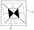
- FIG. 1 is a diagram showing a calibration target 10 according to the present embodiment.
- the calibration target 10 includes at least two straight lines 2 and an enclosing figure 4 that are formed on the same plane.
- at least two straight lines 2 are two straight lines 2a and 2b.
- the surrounding figure 4 is a figure surrounding the two straight lines 2 described above, and corresponds to the quadrangle 4a in the present embodiment.
- the two straight lines 2a and 2b in the quadrangle 4a are defined so as to have an angle with respect to a horizontal plane of the field of view of the in-vehicle camera 20 and a vertical plane perpendicular to the horizontal plane. Further, the two straight lines 2 are arranged so as to form an intersection 6.
- the calibration target detection apparatus 200 detects photometric information for each predetermined area by the detection unit 21 of the in-vehicle camera 20, and specifies the position of the calibration target 10 based on the difference in the photometric information. To do.
- an area 8 divided by two straight lines 2 is colored with a check pattern so that a difference in photometric information for each area is conspicuous.
- the region 8 is divided into four regions 8a-8d. These regions 8a-8d are colored with a check pattern so as to have a different color from the adjacent regions as shown in FIG.
- the check pattern is not particularly limited, but for example, it is preferable to use a combination of clear colors such as a combination of white and black or a combination of blue and red.
- the calibration target 10 is configured to have an appropriate size so that the detection unit 21 of the in-vehicle camera 20 can detect photometric information.
- the length of one side of the quadrangle 4a for calibrating the surrounding figure 4 is preferably about 400 mm.
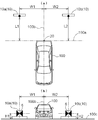
- FIG. 2A is a bird's-eye view showing the positional relationship between the vehicle 100 and the calibration target 10.
- FIG. 2B is an elevational view showing the positional relationship between the vehicle 100 and the calibration target 10.
- the vehicle-mounted camera 20 to be calibrated in the present embodiment is a back camera that captures the rear of the vehicle 100.
- the in-vehicle camera 20 is disposed in the vicinity of the license plate provided in the outer rear portion of the vehicle 100 or in the vicinity of the emblem provided in the outer rear portion of the vehicle 100.
- the size ratio between the vehicle 100 and the calibration target 10 is ignored in order to clearly indicate the calibration target 10 according to the present invention.
- the calibration target 10 is opposed to the in-vehicle camera 20, and each of them is arranged in a pair apart from each other. That is, as shown in FIGS. 2A and 2B, two are disposed within the field of view of the in-vehicle camera 20.
- Such a calibration target 10 is arranged on the virtual plane so that the orthogonal distance from the rear end surface 100a of the vehicle 100 is a predetermined distance L1 and L2 with a pair of calibration indices 10a and 10b. For example, it is preferable to arrange in a partition form. Further, the calibration indices 10a and 10b are arranged apart from each other.
- the calibration indices 10a and 10b are arranged such that the centers thereof are separated from the center line 100b of the vehicle 100 by W1 and W2, respectively. Further, the calibration targets 10a and 10b are arranged such that their centers (intersection points 6) are separated from the floor surface 100c on which the vehicle 100 is parked by H1 and H2, respectively.
- the calibration targets 10a and 10b are arranged as described above.
- W1 and W2, L1 and L2, H1 and H2 can be arranged to have the same value, or can be arranged to have different values.
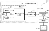
- FIG. FIG. 3 is a block diagram schematically showing the configuration of a calibration target detection apparatus 200 according to the present invention and a calibration apparatus 300 that calibrates the in-vehicle camera 20 using the calibration target 10 detected by the calibration target detection apparatus 200. It is.
- the calibration target detection apparatus 200 includes an in-vehicle camera 20 and a position calculation unit 30.
- the in-vehicle camera 20 includes functional units such as a photometric unit 21, a photometric area setting unit 22, and a luminance profile generation unit 23 (corresponding to the profile generation unit of the present application).
- the calibration device 300 includes a calibration target detection device 200, a correction camera angle calculation unit 40, a drawing unit 41, and a display 42.
- the above-described functional unit for performing various processes for calibrating the in-vehicle camera 20 using the CPU as a core member is hardware and / or software. Has been built.
- the photometric area setting unit 22 sets a long photometric area RM.
- the photometric area RM is an area in which luminance is measured, and is set within the visual field range of the in-vehicle camera 20.
- the photometric area RM is set in a long shape, and the photometric area setting unit 22 is set with coordinates corresponding to the visual field range of the in-vehicle camera 20.
- the visual field range in the present embodiment corresponds to a range displayed as a finder image captured by the in-vehicle camera 20 in the finder state.
- the corresponding coordinates are specifically two points (for example, the first coordinate and the second coordinate) on the diagonal line of the photometric region RM, and the photometric region setting unit 22 has the first coordinate and the second coordinate within the visual field range. Set the coordinates. The two coordinates set in this way are transmitted to the photometric unit 21 described later.
- the photometry area RM set by the photometry area setting unit 22 is not fixed at a specific position within the field of view range of the in-vehicle camera 20, and when two coordinates are designated again, other positions It is possible to reset.
- Such a photometric area setting unit 22 can be configured by a CPU (Central Processing Unit) or an ECU (Electronic Control Unit) provided in the in-vehicle camera 22.
- a CPU Central Processing Unit
- ECU Electronic Control Unit
- two calibration targets 10a and 10b are used as shown in FIG. Therefore, when measuring the luminance of the calibration targets 10a and 10b, the photometry area setting unit 22 sets a photometry area RM corresponding to each calibration target 10a and 10b.
- the detecting unit 21 detects photometric information in the photometric area RM. That is, the photometry unit 21 measures the luminance of the photometry area RM.
- the photometric area RM that is a photometric target of the photometric unit 21 is set by the photometric area setting unit 22 described above.
- Luminance is an index indicating brightness (darkness). Therefore, the luminance of the photometric area RM indicates the brightness (darkness) of the area set by the photometric area setting unit 22.
- the brightness of such a region for example, the brightness in the region may be obtained by a simple average or may be obtained by a weighted average.
- the photometry unit 21 corresponds to an exposure meter provided in the in-vehicle camera 20. Therefore, since it is not necessary to provide a new functional unit having a photometric function, the calibration target detection apparatus 200 can be realized at low cost.
- the photometry unit 21 performs exposure adjustment based on a predetermined threshold value set in advance.
- a predetermined threshold value set in advance is particularly effective when the place to be measured is dark. That is, when the place to be metered is dark, exposure adjustment is performed so that the luminance above a predetermined threshold set in advance becomes brighter. Further, the exposure adjustment may be performed so that the luminance lower than a predetermined threshold value set in advance becomes darker. The luminance measured by the photometry unit 21 in this way is transmitted to a luminance profile generation unit 23 described later.
- the luminance profile generator 23 generates a first luminance profile (corresponding to the first profile of the present application).
- the first luminance profile is a profile in which a long photometric region RM having a predetermined one direction as a long direction is scanned along another direction orthogonal to the one direction and shows a change in luminance in the other direction. is there.
- the predetermined one direction is a vertical direction.
- the other direction orthogonal to one direction is a horizontal direction.
- the long direction is a long longitudinal direction. Therefore, the first luminance profile in the present embodiment corresponds to a profile indicating a change in luminance in the horizontal direction obtained by scanning a long photometric region RM having the vertical direction in the longitudinal direction along the horizontal direction. To do.
- one direction is a vertical direction and the other direction is a horizontal direction.
- the photometry area setting unit 22 sets the photometry area RM so that the coordinates are sequentially shifted along the horizontal direction.
- the photometric region RM is set in a long shape with the vertical direction as the longitudinal direction.
- the length in the longitudinal direction of the photometric region RM is at least longer than the length in the vertical direction of a detection target region (a calibration target existence region F described later in this embodiment) that is a detection target of luminance.
- the luminance profile generation unit 23 generates a second luminance profile (corresponding to the second profile of the present application).
- the second luminance profile is generated after the above-described first luminance profile is acquired.
- the second luminance profile is a profile indicating a change in luminance in one direction when a long photometric region RM having the other direction as a long direction is scanned along the one direction.
- one direction is the vertical direction and the other direction is the horizontal direction. Therefore, the second luminance profile in the present embodiment corresponds to a profile indicating a change in luminance in the vertical direction obtained by scanning a long photometric region RM having the horizontal direction as the longitudinal direction along the vertical direction. To do.
- the photometry area setting unit 22 sets the photometry area RM so that the coordinates are sequentially shifted along the vertical direction.
- the photometric region RM is set in a long shape with the horizontal direction as the longitudinal direction. In this case, the length in the longitudinal direction of the photometric region RM is at least longer than the length in the horizontal direction of a detection target region (a calibration target existence region F described later in this embodiment) that is a luminance detection target.
- a detection target region (a calibration target existence region F described later in this embodiment) that is a luminance detection target.
- the luminance profile generation unit 23 that generates the first luminance profile and the second luminance profile can be configured by a DSP (Digital Signal Processor) included in the in-vehicle camera 22.
- DSP Digital Signal Processor
- two calibration targets 10a and 10b are used as shown in FIG. Therefore, the luminance profile generation unit 23 generates the first luminance profile and the second luminance profile for each of the calibration targets 10a and 10b.
- the luminance profile generation unit 23 transmits a signal indicating that to the photometry region setting unit 22.
- the photometric area setting unit 22 sets the photometric area RM again. This makes it possible to measure the luminance while sequentially changing the position of the photometric area RM.
- the position calculation unit 30 calculates the position of the calibration target 10 used for the calibration of the in-vehicle camera 20 included in the captured image acquired by the in-vehicle camera 20 based on the feature points of the first luminance profile and the second luminance profile.
- the first luminance profile and the second luminance profile are generated and stored by the luminance profile generation unit 23 described above.
- the captured image acquired by the in-vehicle camera 20 is a finder image captured by the in-vehicle camera 20 in the finder state. For this reason, in this embodiment, a captured image is acquired so that the calibration target 10 used for the configuration of the in-vehicle camera 20 is included in the finder image.
- the position calculation unit 30 refers to the first luminance profile and the second luminance profile stored by the luminance profile generation unit 23, extracts feature points of each profile, and calculates the position of the calibration target 10.
- This feature point corresponds to at least one of the edge included in the first luminance profile and the second luminance profile and the middle point of the two edges.
- the characteristics of the calibration target 10 are known at the time of calibrating the in-vehicle camera 20. This is because when the in-vehicle camera 20 is calibrated, the calibration target 10 used for the calibration is selected in advance and arranged at a position as shown in FIG. If the feature of the calibration target 10 is a boundary between lines, the position calculation unit 30 uses the edges of the first luminance profile and the second luminance profile as feature points. If the feature of the calibration target 10 is an intermediate point between the lines, the position calculation unit 30 uses the midpoint of the two edges of the first luminance profile and the second luminance profile as the feature points.
- a feature point may be extracted using both the edge and the middle point of the two edges, and feature points may be extracted by different methods of the first luminance profile and the second luminance profile. Is of course possible.
- Such characteristics of the calibration target 10 are set in advance by the user and stored, for example, in the position calculation unit 30.
- the position calculation unit 30 calculates the position of the calibration target 10 based on the characteristic points of the calibration target 10 as described above. In the present embodiment, two calibration targets 10a and 10b are used as shown in FIG. Therefore, the position calculation unit 30 calculates the positions of both calibration targets 10a and 10b. The position of the calibration target 10 calculated by the position specifying unit 30 is transmitted to a corrected camera angle calculation unit 40 described later. In addition, when calibrating the vehicle-mounted camera 20, the positions of the two calibration targets 10a and 10b as shown in FIG. 2 are specified. The calibration target detection apparatus 200 according to the present invention detects the calibration target 10 in this way and specifies its position.
- the correction camera angle calculation unit 40 calibrates the left and right on the virtual image from the known mounting position of the in-vehicle camera 20, the setting value of the mounting angle at which the in-vehicle camera 20 is mounted, and the positions of the calibration targets 10a and 10b. Corresponding points corresponding to the targets 10a and 10b are calculated, and corrected camera parameters are calculated from the difference from the calibration targets 10a and 10b (particularly the respective intersections 6) calculated by the position calculating unit 30 described above.
- the correction camera parameter means a difference between a design value and an actual value in the camera parameter. Therefore, the actual value is corrected by correcting the design value with the correction camera parameter.
- the calculation of the correction camera angle corresponds to a pair of calibration points (for example, a pair of intersections 6) set from the pair of calibration targets 10a and 10b, and a pair of set points set in advance according to the mounting position of the in-vehicle camera 20 Then, based on the pair of calibration targets 10a and 10b included in the captured image, a correction camera angle for correcting the deviation of the optical axis included when the in-vehicle camera 20 is mounted on the vehicle 100 is calculated.
- the pair of setting points preset according to the mounting position of the in-vehicle camera 20 corresponds to the left and right calibration points on the virtual image.
- a difference between the pair of corresponding points and the pair of calibration points is calculated, and a correction camera angle that corrects the deviation of the optical axis included when the vehicle-mounted camera 20 is mounted on the vehicle 100 is calculated based on the difference.
- the correction camera angle is used to correct the angle of the in-vehicle camera 20.
- the corrected camera angle is obtained by displaying a captured image acquired by the in-vehicle camera 20 on the display 42, and the drawing unit 41 draws a predetermined drawing on the captured image (for example, parks the vehicle 100 in a parking space or moves backward)
- a known parking assistance device or a driving assistance device that assists the driver's driving when traveling is used to superimpose a predicted route line that predicts the course of the vehicle 100).
- the drawing is corrected based on the corrected camera angle so as to be suitable for an actual captured image (captured image captured by the in-vehicle camera 20 installed at the camera angle deviated from the design value). For this reason, the predetermined drawing can be accurately superimposed on the captured image acquired by the in-vehicle camera 20.
- the correction camera angle can be used to correct a captured image by calculating an angle for correcting the angle of the in-vehicle camera 20.
- the angle of the in-vehicle camera 20 includes the angle (rotation angle) of the in-vehicle camera 20 along the vertical direction of the lens of the in-vehicle camera 20, the vertical angle (elevation angle) of the in-vehicle camera 20, and the horizontal angle of the in-vehicle camera 20 ( Azimuth).
- the above-described angle for correcting the angle of the in-vehicle camera 20 is a rotation angle (Roll angle) for correcting the angle of the in-vehicle camera 20 along the vertical direction of the lens of the in-vehicle camera 20, and the vertical of the in-vehicle camera 20. It consists of an elevation angle (Tilt angle) that corrects the angle of the direction and an azimuth angle (Pan angle) that corrects the horizontal angle of the in-vehicle camera 20, and if the corrected camera angle is used, each angle of the in-vehicle camera 20 is corrected. Is possible.
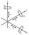
- the vehicle-mounted camera 20 is arranged at the center O with the vertical direction of the lens of the vehicle-mounted camera 20 facing the Z-axis direction in a coordinate system composed of, for example, the X axis, the Y axis, and the Z axis as shown in FIG.
- the Roll angle corresponds to the rotation angle for correcting the angle ( ⁇ R ) around the Z axis in FIG.
- the tilt angle corresponds to an angle for correcting the angle ( ⁇ T ) around the Y axis in FIG.
- the Pan angle corresponds to an angle for correcting the angle ( ⁇ P ) around the X axis in FIG.
- the captured image captured by the in-vehicle camera 20 is rotated (plane rotation) according to the Roll angle, the elevation angle is adjusted according to the Tilt angle, and the tilt angle is adjusted to the Tilt angle. In addition, adjust the horizontal angle. By using such an angle, it is possible to accurately superimpose the predetermined drawing on the captured image as described above, and it is also possible to suppress variations in the imaging range for each product.
- the position of the calibration target 10 specified by the calibration target detection apparatus 200 according to the present invention is used, so that the optical axis included when the vehicle-mounted camera 20 is mounted on the vehicle 100 is adjusted. The deviation can be suitably calibrated (corrected).
- the captured image itself acquired by the in-vehicle camera 20 is corrected using the rotation angle, the elevation angle, and the azimuth angle for correcting the angle of the in-vehicle camera 20. It is also possible to display on the display 42. Alternatively, by correcting the position of a display object (for example, a lane or an object) included in the captured image acquired by the in-vehicle camera 20 using the rotation angle, the elevation angle, and the azimuth angle that correct the angle of the camera 20 described above. It is also possible to use it for specifying an accurate position.
- a display object for example, a lane or an object
- the photometric area setting unit 22 sets the photometric area RM measured by the photometric unit 21 in a long shape.
- the photometric area setting unit 22 does not set an area for photometry over the entire imaging range that can be captured by the in-vehicle camera 20.
- the photometric area setting unit 22 is a known mounting position of the in-vehicle camera 20, a setting value of the mounting angle of the in-vehicle camera 20, an arrangement position of the calibration targets 10 a and 10 b, a variation in the mounting angle of the in-vehicle camera 20, Is set in the calibration target existence area F where the calibration target 10 is predicted to exist.
- the detection of the calibration target 10 of the in-vehicle camera 20 will be specifically described.
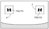
- the in-vehicle camera 20 captures a scene as shown in FIG. 5 as a finder image.
- the calibration targets 10 a and 10 b exist in the calibration target existence area F.
- the calibration index existence area F is set based on the mounting tolerance of the in-vehicle camera 20 (in consideration of the mounting tolerance of the in-vehicle camera 20). Therefore, in a factory or the like where the in-vehicle camera 20 is mounted, when mounted on the vehicle 100 within a predetermined error range set in advance, the calibration targets 10a and 10b are basically as indicated by the white arrows in FIG. Even if the position varies in the calibration target existence area F, it is located inside the calibration target existence area F.
- the area (the area to be scanned) detected by the photometry unit 21 may be the calibration target existence area F that is a part of the captured image of the in-vehicle camera 20. That is, the photometric area RM that the photometric unit 21 measures is only required to be inside the calibration target existence area F. Therefore, the photometric area setting unit 22 sets the photometric area RM so that the photometric unit 21 can scan the inside of the calibration target existence area F and perform photometry. With such a configuration, since it is not necessary to perform photometry over the entire range displayed as the finder image of the in-vehicle camera 20, the time required for photometry can be shortened and the processing load required for photometry is reduced. It becomes possible to reduce. Accordingly, since the photometric unit 21 with low performance can be used, it can be realized at low cost.
- the photometric area setting unit 22 sets the photometric area RM so that the photometric unit 21 scans the inside of the calibration target existence area F and performs photometry.
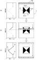
- the photometric area setting unit 22 sets the photometric area RM to scan the inside of the calibration target existence area F in the horizontal direction as shown in FIG.
- the photometric area RM is set to a long photometric area RM whose longitudinal direction is the vertical direction.
- the vertical length of the photometric area RM is set to be at least the vertical length of the calibration target existence area F.
- the horizontal length of the photometric region RM is set according to the resolution of the in-vehicle camera 20. More specifically, it is set with several pixels. For example, when the calibration target existence area F shown in FIG. 7 is an area of 100 pixels ⁇ 100 pixels, the vertical length is set to 100 pixels and the horizontal length is set to 8 pixels.
- the photometry unit 21 measures the luminance of the photometry region RM set by the photometry region setting unit 22 in this way.
- the photometry unit 21 does not measure the luminance of the captured image captured and stored by the in-vehicle camera 20, but measures the luminance when the in-vehicle camera 20 is in the finder state. Therefore, in the luminance photometry state, only a captured image captured by the finder function is displayed.
- the photometry area setting unit 22 sets the photometry area RM to be measured next. Do. At this time, the vertical length of the photometric area RM to be set is set to be equal to or longer than the vertical length of the calibration target existence area F as in FIG. Further, the horizontal position of the photometric region RM is set by shifting one pixel from the position shown in FIG. Therefore, the long photometric area RM is slid by 1 pixel in the horizontal direction.
- the average luminance can be reduced by setting the displacement amount (for example, 1 pixel) of the slide movement to at least the horizontal length (for example, 8 pixels). It is possible to meter changes.
- FIG. 7 (b) shows a state in the middle
- the process is performed up to the end of the calibration target existence area F in the horizontal direction.
- the photometric area RM is scanned in the horizontal direction, and a change in luminance in the horizontal direction can be acquired.
- the luminance change acquired in this way is transmitted to the luminance profile generation unit 23, and the luminance profile generation unit 23 generates a first luminance profile indicating the horizontal luminance change.
- a first luminance profile is also shown in FIG.
- the vertical axis represents the intensity of the luminance
- the horizontal axis represents the step (corresponding to the position in the horizontal direction) at which the photometric luminance was acquired.
- the calibration target 10 used in the present embodiment has only a bright portion (white portion) at the beginning of photometry as shown in FIG. 7C, and therefore the luminance is constant (P 1 ).
- the metering area RM reaches the calibration target 10, the luminance for dark part (black portion) sharply increases decreases from P 1.
- the luminance starts increases when the horizontal direction of the total width of the metering area RM is completely overlaps the calibration target 10, a shape having a peak P H.
- the luminance decreases until the photometric area RM starts to move away from the calibration target 10.
- Luminance in this case is P 2.
- the brightness increases.
- the photometric area RM is completely separated from the calibration target 10, the brightness becomes a constant value.
- Position calculating unit 30 on the basis of the peak P H is a feature point from such first intensity profile, it is possible to identify the intersection 6 of the two straight lines 2a and 2b.
- the photometric area RM is set with a width of 8 pixels in the horizontal direction.
- the peak P H becomes the metering area RM is not necessarily obtained when reaching the intersection 6, obtained when the horizontal center of the metering area RM reaches the intersection 6.
- the position calculation unit 30, from the time that the peak P H was obtained (position coordinates), half of the horizontal width of the metering area RM (4 pixels in this embodiment) back position is the center of the calibration target 10 Identify a point.
- the calibration target 10 specifies that the calibration target 10 is located between the position where the luminance falls from a certain value (P 1 ) and the position where the luminance P 2 is measured.
- the photometry area setting unit 22 sets the photometry area RM so as to move in the vertical direction that is a direction orthogonal to the horizontal direction.
- FIG. 8A shows the state at the start of the photometry.
- the photometry unit 21 measures the luminance accordingly.
- the length of the photometry area RM in the vertical direction is set to be at least the length of the calibration target existence area F in the horizontal direction. Further, the vertical length of the photometric region RM is set to several pixels (for example, 8 pixels) as in the horizontal scanning described above.
- the photometric area setting unit 22 performs the photometric area setting similarly to the above-described horizontal scanning.
- the RM is slid by one pixel in the vertical direction, and the photometry unit 21 performs luminance photometry.
- the average luminance can be reduced by setting the displacement amount (for example, 1 pixel) of the slide movement to at least the length in the vertical direction (for example, 8 pixels). It is possible to meter changes.
- Such setting of the photometric area RM and luminance photometry are continuously performed as shown in FIG. 8B, and finally performed to the end in the vertical direction shown in FIG. 8C. .
- the luminance change acquired in this way is transmitted to the luminance profile generation unit 23, and the luminance profile generation unit 23 generates a second luminance profile indicating the luminance change in the vertical direction.
- FIG. 8 also shows the second luminance profile generated in this way.
- the vertical axis represents the intensity of the luminance
- the horizontal axis represents the step (corresponding to the position in the horizontal direction) at which the photometric luminance was acquired. Since there is only a bright part (white part) at the beginning of photometry, the brightness is constant (P 3 ). Thereafter, the metering area RM reaches the calibration target 10, the luminance for dark part (black portion) increases gradually decreases from P 3. As the dark portion increases, the luminance decreases, and the luminance profile has a shape having a peak P V. After that, the luminance increases and becomes a constant value (P 4 ) when the photometric region RM is completely separated from the calibration target 10.
- the position calculation unit 30 can specify the intersection 6 of the two straight lines 2a and 2b based on the peak P V that is a feature point from such a second luminance profile.
- the photometric area RM is set with a width of 8 pixels in the vertical direction. Therefore, the peak P V is not obtained when the photometric region RM reaches the intersection point 6, but is obtained when the vertical center of the photometric region RM reaches the intersection point 6. Therefore, the position calculation unit 30 determines that the position where the half of the vertical width of the photometric region RM (4 pixels in the present embodiment) has returned from the point in time when the peak P V is obtained (position coordinates) is the center of the calibration target 10. Identify a point.
- the position calculation unit 30, and a position lowered from the luminance is constant value (P 3), and positions the calibration target 10 between a position backward 8 pixels from the position where a predetermined value again (P 4) To be identified.
- FIG. 9 is a flowchart relating to detection of the calibration target 10 by the calibration target detection apparatus 200.
- FIG. 9 also shows a flow related to the calibration apparatus 300 that calibrates the in-vehicle camera 20 using the position of the calibration target 10 detected by the calibration target 200.
- step # 02 exposure adjustment of the calibration target existence area F is performed (step # 02).
- the exposure adjustment is performed in accordance with the brightness of the calibration target existence area F, and is adjusted so that a bright portion that is equal to or greater than a predetermined threshold set in advance is conspicuous.
- the photometry area setting unit 22 sets the photometry area RM for the horizontal direction (step # 03).
- Such a photometric area RM corresponds to an area in which the photometric unit 21 performs photometry, and is set as a long photometric area RM.
- the process of setting the long photometric area RM in this way is called a photometric area setting process.
- the photometry unit 21 measures the luminance in the photometry region RM (step # 04).
- the process in which the photometry unit 21 performs photometry (detection) on the luminance (photometry information) of the photometry region RM in this manner is referred to as a photometry process (detection process).
- the luminance measured by the photometry unit 21 is transmitted to the luminance profile generation unit 23 and stored (step # 05).
- the photometry area setting unit 22 sets the photometry area RM in the horizontal direction. Is set by shifting by a predetermined amount (step # 07). Thereafter, the processing is continued from step # 04.
- the photometry area setting unit 22 sets the photometry area RM for the vertical direction (step # 08).
- Such a photometric area RM corresponds to an area in which the photometric unit 21 performs photometry, and is set as a long photometric area.
- the process of setting the long photometric area RM in this way is called a photometric area setting process.
- the photometry unit 21 measures the luminance in the photometry area RM (step # 09).
- the process in which the photometry unit 21 performs photometry (detection) on the luminance (photometry information) of the photometry region RM in this manner is referred to as a photometry process (detection process).
- the luminance measured by the photometry unit 21 is transmitted to and stored in the luminance profile generation unit 23 (step # 10).
- the photometry area setting unit 22 sets the photometry area RM in the vertical direction. Is set by shifting by a predetermined amount (step # 12). Thereafter, the processing is continued from step # 09.
- step # 11 Yes
- a first luminance profile first profile
- a second luminance profile second profile indicating a change in luminance in the vertical direction
- a luminance profile generation step profile generation step
- the position of (center point) 6 is calculated (step # 13). Such a process is called a position calculation process.
- the calibration target detection apparatus 200 according to the present invention specifies the position of the calibration target 10 in this way.
- step # 14: No If there is a calibration target 10 in addition to the calibration target 10 whose position has been calculated as described above (step # 14: No), the process returns to step # 03, and the position of the other calibration target 10 is calculated.
- step # 14: Yes the calibration device 300 of the vehicle-mounted camera 20 detects the deviation amount based on the position of the calibration target 10 specified by the calibration target detection device 200 ( Step # 15). This deviation amount corresponds to a rotation angle, an elevation angle, and an azimuth angle for correcting the angle of the camera 20, and the deviation amount is stored in a predetermined storage unit (step # 16). Processing is performed along such a flow.
- the calibration target 10 has an angle 8 with respect to the horizontal plane of the field of view of the in-vehicle camera 20 and a vertical plane perpendicular to the horizontal plane, and the region 8 delimited by at least two straight lines 2 forming the intersection 6. It was explained that it was colored with a check pattern.
- the scope of application of the present invention is not limited to this.
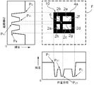
- an area delimited by a plurality of straight lines 2a-2h having no angle with respect to the horizontal plane of the field of view of the in-vehicle camera 20 and the vertical plane perpendicular to the horizontal plane as shown in FIG. 10 is colored with a check pattern. It is also possible to use a certain calibration target 10.
- FIG. 10 shows a calibration target 10 according to another embodiment. Further, a first luminance profile indicating a change in luminance in the horizontal direction is shown below the calibration target 10, and a second luminance profile indicating a change in luminance in the vertical direction is shown on the left side of the calibration target 10. Even if the calibration target 10 is composed of a plurality of straight lines 2a-2h having no angle with respect to the horizontal plane in the field of view of the in-vehicle camera 20 and the vertical plane perpendicular to the horizontal plane as shown in FIG. A profile can be generated. From the first luminance profile shown in FIG.
- the calibration target 10 is located between the position where the luminance falls from the constant value (P 1 ) and the position where the luminance (P 2 ) was obtained before finally reaching the constant value. It is possible to specify that it is located. Further, according to the second luminance profile shown in FIG. 10, the calibration target 10 has a position where the luminance falls from a constant value (P 3 ) and a position where the luminance (P 4 ) is obtained before finally reaching the constant value. It is possible to specify that it is located between.
- the centers of the straight lines 2b, 2c, 2f and 2g can be specified as the center point 6 of the calibration target 10. If according is identified as the center of the straight line 2b and 2c the middle point of the two edges P 11 and P 21 in the first intensity profile. Further, the midpoint of the two edges P 31 and P 41 in the second luminance profile is specified as the center of the straight lines 2f and 2g.
- the calibration target detection apparatus 200 includes the calibration target 10 including the horizontal plane in the field of view of the in-vehicle camera 20 and the plurality of straight lines 2a-2h having no angle with respect to the vertical plane perpendicular to the horizontal plane. Even if it exists, it is possible to detect suitably.
- a calibration target 10 including a plurality of straight lines 2a and 2b having an angle with respect to a horizontal plane in the field of view of the in-vehicle camera 20 and a vertical plane perpendicular to the horizontal plane as shown in FIG. Is possible.
- a first luminance profile showing a change in luminance in the horizontal direction is shown below the calibration target 10
- a second luminance profile showing a change in luminance in the vertical direction is shown on the left side of the calibration target 10.
- the calibration target 10 has the photometric area RM from the position where the luminance decreases from the constant value (P 1 ) and finally the constant value (P 2 ) in the first luminance profile.
- the calibration target 10 is located between the position where the luminance falls from the constant value (P 3 ) and the position where the luminance (P 4 ) was obtained before finally reaching the constant value. Can be identified.
- the square 3 may be a circle, for example. Even with such a calibration target 10, it is possible to preferably specify the position of the calibration target 10 and the intersection (center point) 6 (the position of a predetermined part of the calibration target 10).
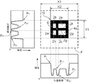
- the photometric area setting unit 22 has been described as setting the photometric area RM to slide within the calibration target existence area F. That is, in the calibration index 10 shown in FIG. 12, the luminance measurement in the horizontal direction is performed in the range of X1 with Y1 as the long longitudinal direction, and the luminance measurement in the vertical direction is performed in the long X1 direction. It has been described that the process is performed in the range of Y1 as the longitudinal direction. However, the scope of application of the present invention is not limited to this.
- the position calculation unit 30 can specify the horizontal position of the calibration target 10 based on the first luminance profile indicating the change in luminance in the horizontal direction. That is, in FIG.
- the position calculation unit 30 can specify that the calibration target 10 is within the range indicated by X2 based on the first luminance profile. Therefore, in the luminance measurement in the vertical direction performed after the luminance measurement in the horizontal direction, it is possible to calibrate so that X2 is performed in the range of Y1 with the long longitudinal direction. According to such a method, it is specified that the calibration target 10 does not exist in a region outside X2 in the horizontal direction according to the first luminance profile generated by the photometry of the luminance in the horizontal direction previously performed. Therefore, it is not necessary to perform photometry on an unnecessary region (region outside X2 in the horizontal direction). Therefore, the calculation processing load can be reduced, and the time required for detecting the calibration target 10 can be shortened.
- FIG. 12 shows the first brightness profile (the brightness profile shown at the bottom of the calibration target 10) and the second brightness profile (the brightness profile shown at the left of the calibration target 10) acquired in this way.
- the second luminance profile showing the change in luminance in the vertical direction shown in FIG. 12 is a luminance profile measured by taking the long longitudinal direction as X2.
- the calibration target 10 has a luminance (P 2 ) before the luminance finally falls to a position where the luminance falls from the constant value (P 1 ). It is possible to specify that it is located between the obtained positions.
- the calibration target 10 is located between the position (P 3 ) where the luminance is first obtained and the position (P 4 ) where the luminance is finally obtained. It is possible to specify. It is also possible to specify the midpoint of the two edges P 11 and P 21 of the first luminance profile and the midpoint of the two edge peak values P 31 and P 41 of the second luminance profile as the center of the calibration target 10. It is.
- the calibration target 10 shown in FIG. 13 can be used as one simple calibration target 10.
- a first luminance profile showing a change in luminance in the horizontal direction is shown below the calibration target 10
- a second luminance profile showing a change in luminance in the vertical direction is shown on the left side of the calibration target 10.
- the calibration target 10 is between the position where the luminance falls from the constant value (P 11 ) and the position where the luminance (P 21 ) was obtained before finally reaching the constant value. It is possible to specify that it is located.
- the calibration target 10 has a position where the luminance falls from a constant value (P 31 ) and a position where the luminance (P 41 ) is obtained before finally reaching the constant value. It is possible to specify that it is located between.
- the calibration target detection apparatus 200 can suitably detect even a simple calibration target 10 as shown in FIG. Further, in the calibration target 10 shown in FIG. 13, the square inside the calibration target 10 can be circular or other shapes can be naturally used. Even with such a calibration target 10, it is possible to preferably specify the position and center point 6 of the calibration target 10.
- the photometry unit 21 has been described as performing photometry of the luminance of the photometry region RM set in the finder image of the in-vehicle camera 20. That is, it has been described that luminance is measured using a captured image temporarily stored in a buffer memory or the like provided in the in-vehicle camera 20.
- the scope of application of the present invention is not limited to this. It is also possible to set a photometric area RM for a captured image once acquired by the in-vehicle camera 20, that is, a captured image stored in a storage memory or the like included in the in-vehicle camera 20, and measure the luminance. is there. Even such a calibration target detection apparatus 200 for calibration is naturally within the scope of the present invention.
- the photometric area setting unit 22 has been described assuming that the length of the photometric area RM in the short direction is 8 pixels. Further, it has been described that the amount of movement set for sliding movement is one pixel. These are merely examples. Therefore, it is possible to set with another amount, and when sliding, it is set so that the photometry area RM previously measured and the photometry area RM set later do not overlap at all. Is of course possible.
- the calibration target detection apparatus 200 and the method for detecting the calibration target 10 have been described.
- the program of the calibration index target detection apparatus 200 that is preferably used for the calibration target detection apparatus 200 is also included in the scope of rights.
- a characteristic configuration of the program is that a computer executes a photometry area setting function for setting a long photometry area RM and a detection function for detecting photometry information of the photometry area RM, and a predetermined one direction is long.
- a long photometric region RM as a direction is scanned along another direction orthogonal to one direction to generate a first profile indicating a change in photometric information in the other direction, and the other direction is defined as a long direction.
- the long photometry area RM is scanned along one direction, and a profile generation function for generating a second profile indicating a change in photometry information in the one direction, and feature points of the first profile and the second profile And a position calculation function for calculating the position of the calibration target 10 used for the calibration of the in-vehicle camera 20 included in the captured image acquired by the in-vehicle camera 20 based on the computer.
- a program for the calibration target detection apparatus 200 can also obtain the above-described effects, as in the calibration target detection method for detecting the calibration target 10 as the object of the present invention described above.
- Various additional feature configurations can be provided.
- one direction has been described as the vertical direction, and the other direction has been described as the horizontal direction.
- the scope of application of the present invention is not limited to this.
- one direction and the other direction may be directions other than the horizontal direction and the vertical direction. That is, it is sufficient that one direction and the other direction are orthogonal to each other.
- the setting of the photometric area RM has been described on the assumption that the photometric area setting unit 22 is set by coordinates so that the photometric area RM slides within the calibration target existence area F.
- the scope of application of the present invention is not limited to this.
- the calibration target 10 is described as being arranged on the screen.
- the scope of application of the present invention is not limited to this. For example, even if the calibration target 10 is painted on the floor, it is naturally possible to detect the calibration target 10 by the calibration target detection apparatus 200.
- the position and center of the calibration target 10 are specified based on the feature points of the first luminance profile and the second luminance profile, and it has been described as specifying in consideration of the width of the photometric region RM.
- the scope of application of the present invention is not limited to this.
- the width of the photometric area RM is small, it is naturally possible to specify the position and center of the calibration target 10 while ignoring the width.
- the calibration target 10 exists between a position where the luminance is reduced from the constant value (P 1 ) and a position where the luminance finally becomes the constant value. and, it is possible to specify a position where the peak P H is obtained is the intersection 6 of the calibration target 10.
- the calibration target 10 exists between the position where the luminance is reduced from the constant value (P 3 ) and the position where the luminance finally becomes the constant value. Then, it is possible to specify that the position where the peak P V is obtained is the intersection 6 of the calibration target 10. In this manner, it is naturally possible to specify the position and center of the calibration target 10 while ignoring the width of the photometric region RM.
- the detection unit 21 is the photometric unit 21 and the photometric information of the photometric region RM is described as the luminance of the photometric region RM.
- the photometric information of the photometric area RM can be the color information of the photometric area RM.
- the calibration target 10 is color-coded by blue and red, which are known colors on the apparatus side, and the average color information in the photometric region RM is detected. Even with such a configuration, the position of the calibration target 10 can be suitably specified.
- the calibration target 10 is specified by one scanning each in the horizontal direction and the vertical direction, but the scope of application of the present invention is not limited to this. It is also possible to first specify roughly the region where the calibration target 10 exists by one scanning in each of the horizontal and vertical directions, and then scan the specified region again in the horizontal and vertical directions again. That is, scanning can be repeated. By repeatedly performing in this way, the calibration target 10 can be specified with higher accuracy.
- the center point 6 of the calibration target 10 is specified by scanning the single calibration target 10 in the horizontal direction and the vertical direction.
- the scope of application of the present invention is not limited to this.
- FIG. 14 it is also possible to use a horizontal calibration target 10 and a vertical calibration target 10 arranged side by side. In such a case, first, as shown in FIG. 14, the vertical calibration target 10 disposed on the upper side is scanned in the vertical direction, and a reference line for the vertical direction (indicated by a horizontal broken line in FIG. 14). ) Is detected. Next, as shown in FIG.
- the horizontal calibration target 10 disposed on the lower side is scanned in the horizontal direction to detect a reference line (indicated by a vertical broken line in FIG. 14) with respect to the horizontal direction.
- the intersecting point can be specified as the center point 6 by the reference line for the vertical direction and the reference line for the horizontal direction. Even when such a calibration target 10 is used, naturally the position of the calibration target 10 can be suitably specified.
- the present invention can be used for a calibration target detection device that can be realized at low cost without increasing storage capacity, a calibration target detection method for detecting a calibration target, and a program for the calibration target detection device. .
Landscapes
- Engineering & Computer Science (AREA)
- Multimedia (AREA)
- Signal Processing (AREA)
- Physics & Mathematics (AREA)
- General Physics & Mathematics (AREA)
- Theoretical Computer Science (AREA)
- General Health & Medical Sciences (AREA)
- Biomedical Technology (AREA)
- Health & Medical Sciences (AREA)
- Computer Vision & Pattern Recognition (AREA)
- Studio Devices (AREA)
- Length Measuring Devices By Optical Means (AREA)
- Image Analysis (AREA)
- Measurement Of Optical Distance (AREA)
- Fittings On The Vehicle Exterior For Carrying Loads, And Devices For Holding Or Mounting Articles (AREA)
- Closed-Circuit Television Systems (AREA)
- Image Processing (AREA)
Abstract
Description
上記実施形態では、校正目標10は、車載カメラ20の視野の水平面及び当該水平面に垂直な垂直面に対して角度を有し、交点6を形成する少なくとも2本の直線2により区切られる領域8がチェック模様で彩色されてあるとして説明した。しかしながら、本発明の適用範囲はこれに限定されるものではない。例えば、図10に示されるような車載カメラ20の視野の水平面及び当該水平面に垂直な垂直面に対して角度を有していない複数の直線2a-2hにより区切られる領域が、チェック模様で彩色されてある校正目標10を用いることも可能である。
21:測光部(検出部)
22:測光領域設定部
23:輝度プロファイル生成部(プロファイル生成部)
30:位置算定部
40:補正カメラ角度演算部
41:描画部
42:ディスプレイ
200:校正目標検出装置
300:校正装置
Claims (10)
- 長尺状の測光領域を設定する測光領域設定部と、
前記測光領域の測光情報を検出する検出部と、
所定の一方向を長尺方向とする長尺状の測光領域が、前記一方向に直交する他方向に沿って走査され、前記他方向の測光情報の変化を示す第1プロファイルを生成すると共に、前記他方向を長尺方向とする長尺状の測光領域が、前記一方向に沿って走査され、前記一方向の測光情報の変化を示す第2プロファイルを生成するプロファイル生成部と、
前記第1プロファイル及び前記第2プロファイルの特徴点に基づいて車載カメラにより取得された撮像画像に含まれる前記車載カメラの校正に用いられる校正目標の位置、または、当該校正目標の所定部位の位置を算定する位置算定部と、
を備える校正目標検出装置。 - 前記測光領域の測光情報が、測光領域の輝度である請求項1に記載の校正目標検出装置。
- 前記測光領域の測光情報が、測光領域の色情報である請求項1に記載の校正目標検出装置。
- 前記校正目標が、前記車載カメラの視野の水平面及び当該水平面に垂直な垂直面に対して角度を有し、交点を形成する少なくとも2本の直線により区切られる領域がチェック模様で彩色されてある請求項1から3のいずれか一項に記載の校正目標検出装置。
- 前記検出部が、予め設定された所定の閾値に基づいて露光調整を行う請求項1から4のいずれか一項に記載の校正目標検出装置。
- 前記特徴点が、前記第1プロファイル及び前記第2プロファイルに含まれるエッジ及び2つのエッジの中点の少なくともいずれか一方である請求項1から5のいずれか一項に記載の校正目標検出装置。
- 前記検出部が検出する領域は、前記車載カメラの撮影画像の一部である校正目標存在領域である請求項1から6のいずれか一項に記載の校正目標検出装置。
- 前記校正目標存在領域は、前記車載カメラの取り付け公差に基づいて設定される請求項7に記載の校正目標検出装置。
- 長尺状の測光領域を設定する測光領域設定工程と、
前記測光領域の測光情報を検出する検出工程と、
所定の一方向を長尺方向とする長尺状の測光領域が、前記一方向に直交する他方向に沿って走査され、前記他方向の測光情報の変化を示す第1プロファイルを生成すると共に、前記他方向を長尺方向とする長尺状の測光領域が、前記一方向に沿って走査され、前記一方向の測光情報の変化を示す第2プロファイルを生成するプロファイル生成工程と、
前記第1プロファイル及び前記第2プロファイルの特徴点に基づいて車載カメラにより取得された撮像画像に含まれる前記車載カメラの校正に用いられる校正目標の位置、または、当該校正目標の所定部位の位置を算定する位置算定工程と、
を備える校正目標検出方法。 - 長尺状の測光領域を設定する測光領域設定機能と、
前記測光領域の測光情報を検出する検出機能と、
所定の一方向を長尺方向とする長尺状の測光領域が、前記一方向に直交する他方向に沿って走査され、前記他方向の測光情報の変化を示す第1プロファイルを生成すると共に、前記他方向を長尺方向とする長尺状の測光領域が、前記一方向に沿って走査され、前記一方向の測光情報の変化を示す第2プロファイルを生成するプロファイル生成機能と、
前記第1プロファイル及び前記第2プロファイルの特徴点に基づいて車載カメラにより取得された撮像画像に含まれる前記車載カメラの校正に用いられる校正目標の位置、または、当該校正目標の所定部位の位置を算定する位置算定機能と、
をコンピュータに実行させる校正目標検出装置のためのプログラム。
Priority Applications (4)
| Application Number | Priority Date | Filing Date | Title |
|---|---|---|---|
| EP10780324.9A EP2437495B1 (en) | 2009-05-27 | 2010-02-18 | Calibration target detection apparatus, calibration target detecting method for detecting calibration target, and program for calibration target detection apparatus |
| KR1020117030887A KR101419721B1 (ko) | 2009-05-27 | 2010-02-18 | 교정목표 검출장치와, 교정목표를 검출하는 교정목표 검출방법과, 교정목표 검출장치를 위한 프로그램 |
| CN201080023236.7A CN102450005B (zh) | 2009-05-27 | 2010-02-18 | 校正目标检测装置、检测校正目标的校正目标检测方法 |
| US13/265,103 US8605156B2 (en) | 2009-05-27 | 2010-02-18 | Calibration target detection apparatus, calibration target detecting method for detecting calibration target, and program for calibration target detection apparatus |
Applications Claiming Priority (2)
| Application Number | Priority Date | Filing Date | Title |
|---|---|---|---|
| JP2009128206A JP5471038B2 (ja) | 2009-05-27 | 2009-05-27 | 校正目標検出装置と、校正目標を検出する校正目標検出方法と、校正目標検出装置のためのプログラム |
| JP2009-128206 | 2009-05-27 |
Publications (1)
| Publication Number | Publication Date |
|---|---|
| WO2010137364A1 true WO2010137364A1 (ja) | 2010-12-02 |
Family
ID=43222490
Family Applications (1)
| Application Number | Title | Priority Date | Filing Date |
|---|---|---|---|
| PCT/JP2010/052448 Ceased WO2010137364A1 (ja) | 2009-05-27 | 2010-02-18 | 校正目標検出装置と、校正目標を検出する校正目標検出方法と、校正目標検出装置のためのプログラム |
Country Status (6)
| Country | Link |
|---|---|
| US (1) | US8605156B2 (ja) |
| EP (1) | EP2437495B1 (ja) |
| JP (1) | JP5471038B2 (ja) |
| KR (1) | KR101419721B1 (ja) |
| CN (1) | CN102450005B (ja) |
| WO (1) | WO2010137364A1 (ja) |
Families Citing this family (24)
| Publication number | Priority date | Publication date | Assignee | Title |
|---|---|---|---|---|
| JP5091902B2 (ja) * | 2009-03-31 | 2012-12-05 | アイシン精機株式会社 | 車載カメラの校正に用いられる校正指標と、当該校正指標を用いた車載カメラの校正方法と、システムと、当該システムのためのプログラム |
| FR2979989B1 (fr) * | 2011-09-13 | 2016-01-08 | Fb Technology | Equipement mobile de controle des feux de balisage aeroportuaire |
| JP5959311B2 (ja) * | 2012-05-25 | 2016-08-02 | 富士通テン株式会社 | データ導出装置、及び、データ導出方法 |
| JP5820787B2 (ja) * | 2012-08-30 | 2015-11-24 | 株式会社デンソー | 画像処理装置、及びプログラム |
| JP6009894B2 (ja) * | 2012-10-02 | 2016-10-19 | 株式会社デンソー | キャリブレーション方法、及びキャリブレーション装置 |
| US9648249B2 (en) * | 2013-11-20 | 2017-05-09 | Canon Kabushiki Kaisha | Image capturing apparatus, method of controlling the same, and storage medium |
| FR3015660B1 (fr) * | 2013-12-19 | 2020-06-05 | Continental Automotive France | Procede, support et systeme de calibration d'une camera d'un vehicule |
| CN104019752B (zh) * | 2014-05-29 | 2015-11-25 | 京东方科技集团股份有限公司 | 显示屏的厚度均匀性检测方法、装置及系统 |
| KR101594740B1 (ko) | 2015-09-08 | 2016-02-26 | 김종길 | 충돌물체 좌표산정용 디스플레이 시스템 및 그 구동방법 |
| EP3174007A1 (en) | 2015-11-30 | 2017-05-31 | Delphi Technologies, Inc. | Method for calibrating the orientation of a camera mounted to a vehicle |
| EP3173979A1 (en) | 2015-11-30 | 2017-05-31 | Delphi Technologies, Inc. | Method for identification of characteristic points of a calibration pattern within a set of candidate points in an image of the calibration pattern |
| JP6319670B2 (ja) * | 2016-03-11 | 2018-05-09 | パナソニックIpマネジメント株式会社 | 監視カメラおよびこれを備えた監視カメラシステム |
| CN107590877A (zh) * | 2016-07-08 | 2018-01-16 | 昆山研达电脑科技有限公司 | 行车记录仪拍摄角度的自动检测系统及方法 |
| JP6211157B1 (ja) | 2016-09-01 | 2017-10-11 | 三菱電機株式会社 | キャリブレーション装置およびキャリブレーション方法 |
| EP3534333B1 (en) | 2018-02-28 | 2025-12-17 | Aptiv Technologies AG | Method for calibrating the position and orientation of a camera relative to a calibration pattern |
| EP3534334B1 (en) | 2018-02-28 | 2022-04-13 | Aptiv Technologies Limited | Method for identification of characteristic points of a calibration pattern within a set of candidate points derived from an image of the calibration pattern |
| JP6825743B2 (ja) * | 2018-03-15 | 2021-02-03 | 株式会社Jvcケンウッド | ドライブレコーダ、表示制御方法およびプログラム |
| JP6956051B2 (ja) * | 2018-09-03 | 2021-10-27 | 株式会社東芝 | 画像処理装置、運転支援システム、画像処理方法及びプログラム |
| KR20200050612A (ko) * | 2018-11-02 | 2020-05-12 | 현대자동차주식회사 | 차량용 레이더의 영점 조절 장치 및 그 방법 |
| JP7215231B2 (ja) * | 2019-03-04 | 2023-01-31 | トヨタ自動車株式会社 | 情報処理装置、検知方法及びプログラム |
| US12266144B2 (en) * | 2019-11-20 | 2025-04-01 | Nvidia Corporation | Training and inferencing using a neural network to predict orientations of objects in images |
| US20250042693A1 (en) * | 2021-06-02 | 2025-02-06 | Mitsubishi Electric Corporation | Elevator camera adjustment assistance system |
| GB2623505A (en) * | 2022-10-14 | 2024-04-24 | Belron Int Ltd | Method for assessing illumination set-up for vehicle system calibration |
| US12462428B2 (en) * | 2023-06-05 | 2025-11-04 | GM Global Technology Operations LLC | Sensor angular alignment |
Citations (4)
| Publication number | Priority date | Publication date | Assignee | Title |
|---|---|---|---|---|
| JPH09153139A (ja) * | 1995-11-30 | 1997-06-10 | Sanyo Electric Co Ltd | 映像信号処理装置 |
| JPH09189513A (ja) * | 1996-01-10 | 1997-07-22 | Kawasaki Heavy Ind Ltd | マーカ重心計測方法および装置 |
| JP2007253699A (ja) | 2006-03-22 | 2007-10-04 | Daihatsu Motor Co Ltd | 光軸ずれ検出装置 |
| JP2008131177A (ja) * | 2006-11-17 | 2008-06-05 | Aisin Seiki Co Ltd | 車載カメラの校正装置、校正方法、並びにこの校正方法を用いた車両の生産方法 |
Family Cites Families (9)
| Publication number | Priority date | Publication date | Assignee | Title |
|---|---|---|---|---|
| US6137893A (en) | 1996-10-07 | 2000-10-24 | Cognex Corporation | Machine vision calibration targets and methods of determining their location and orientation in an image |
| JP3565749B2 (ja) * | 1999-09-22 | 2004-09-15 | 富士重工業株式会社 | 車載カメラの撮像方向の検査方法およびその検査装置 |
| JP2002288661A (ja) * | 2001-03-27 | 2002-10-04 | Advantest Corp | 画像検出方法、画像検出装置及びウェハ処理装置 |
| JP4015051B2 (ja) * | 2002-04-22 | 2007-11-28 | 松下電器産業株式会社 | カメラ補正装置 |
| CN101014119B (zh) * | 2006-02-08 | 2011-04-13 | 财团法人工业技术研究院 | 车辆辅助监视装置与方法 |
| US9007478B2 (en) * | 2007-01-09 | 2015-04-14 | Capso Vision, Inc. | Methods to compensate manufacturing variations and design imperfections in a capsule camera |
| JP2008187564A (ja) | 2007-01-31 | 2008-08-14 | Sanyo Electric Co Ltd | カメラ校正装置及び方法並びに車両 |
| JP4794510B2 (ja) * | 2007-07-04 | 2011-10-19 | ソニー株式会社 | カメラシステムおよびカメラの取り付け誤差の補正方法 |
| US20100245590A1 (en) * | 2007-11-23 | 2010-09-30 | Cazier Robert P | Camera sensor system self-calibration |
-
2009
- 2009-05-27 JP JP2009128206A patent/JP5471038B2/ja active Active
-
2010
- 2010-02-18 WO PCT/JP2010/052448 patent/WO2010137364A1/ja not_active Ceased
- 2010-02-18 KR KR1020117030887A patent/KR101419721B1/ko not_active Expired - Fee Related
- 2010-02-18 EP EP10780324.9A patent/EP2437495B1/en not_active Not-in-force
- 2010-02-18 US US13/265,103 patent/US8605156B2/en not_active Expired - Fee Related
- 2010-02-18 CN CN201080023236.7A patent/CN102450005B/zh not_active Expired - Fee Related
Patent Citations (4)
| Publication number | Priority date | Publication date | Assignee | Title |
|---|---|---|---|---|
| JPH09153139A (ja) * | 1995-11-30 | 1997-06-10 | Sanyo Electric Co Ltd | 映像信号処理装置 |
| JPH09189513A (ja) * | 1996-01-10 | 1997-07-22 | Kawasaki Heavy Ind Ltd | マーカ重心計測方法および装置 |
| JP2007253699A (ja) | 2006-03-22 | 2007-10-04 | Daihatsu Motor Co Ltd | 光軸ずれ検出装置 |
| JP2008131177A (ja) * | 2006-11-17 | 2008-06-05 | Aisin Seiki Co Ltd | 車載カメラの校正装置、校正方法、並びにこの校正方法を用いた車両の生産方法 |
Non-Patent Citations (1)
| Title |
|---|
| See also references of EP2437495A4 |
Also Published As
| Publication number | Publication date |
|---|---|
| CN102450005B (zh) | 2014-08-20 |
| US8605156B2 (en) | 2013-12-10 |
| JP2010276429A (ja) | 2010-12-09 |
| JP5471038B2 (ja) | 2014-04-16 |
| US20120033087A1 (en) | 2012-02-09 |
| KR101419721B1 (ko) | 2014-07-17 |
| EP2437495A4 (en) | 2013-06-12 |
| EP2437495A1 (en) | 2012-04-04 |
| CN102450005A (zh) | 2012-05-09 |
| EP2437495B1 (en) | 2016-11-02 |
| KR20120036317A (ko) | 2012-04-17 |
Similar Documents
| Publication | Publication Date | Title |
|---|---|---|
| JP5471038B2 (ja) | 校正目標検出装置と、校正目標を検出する校正目標検出方法と、校正目標検出装置のためのプログラム | |
| JP5091902B2 (ja) | 車載カメラの校正に用いられる校正指標と、当該校正指標を用いた車載カメラの校正方法と、システムと、当該システムのためのプログラム | |
| US10935643B2 (en) | Sensor calibration method and sensor calibration apparatus | |
| US9967526B2 (en) | Image processing device and storage medium | |
| JP6458439B2 (ja) | 車載カメラ較正装置、画像生成装置、車載カメラ較正方法、画像生成方法 | |
| US8872920B2 (en) | Camera calibration apparatus | |
| US10732412B2 (en) | Display device for vehicle | |
| JP5588812B2 (ja) | 画像処理装置及びそれを用いた撮像装置 | |
| US20110216194A1 (en) | Camera calibration apparatus | |
| JP4861034B2 (ja) | 車載カメラのキャリブレーションシステム | |
| KR101023275B1 (ko) | 차량용 카메라 시스템의 캘리브레이션 방법 및 장치, 차량용 카메라 시스템의 각도상 오정렬을 판단하는 방법 및 이를 수행하는 전자 제어 유닛 | |
| US20090080766A1 (en) | Method and apparatus for the Three-Dimensional Digitization of objects | |
| KR101583663B1 (ko) | 차량용 카메라의 교정판 제공 방법 | |
| JP2008182652A (ja) | カメラ姿勢推定装置、車両、およびカメラ姿勢推定方法 | |
| KR20110015033A (ko) | 타겟 위치 특정 장치 | |
| JP3666348B2 (ja) | 距離認識装置 | |
| JP2012032349A (ja) | ステレオカメラシステム及び該システムを備える車両 | |
| JP5240517B2 (ja) | 車載カメラの校正装置 | |
| US11403770B2 (en) | Road surface area detection device | |
| JP2016225719A (ja) | ステレオカメラ装置、車両、および較正方法 | |
| JP6624383B2 (ja) | キャリブレーション装置及び車載カメラシステム | |
| JP5406898B2 (ja) | 車載カメラの校正装置と、車載カメラの校正方法と、システムと、プログラム | |
| JP2019215789A (ja) | カメラパラメータのキャリブレーション方法及びカメラパラメータのキャリブレーション装置 | |
| JPH1038562A (ja) | 車両用障害物検出装置 |
Legal Events
| Date | Code | Title | Description |
|---|---|---|---|
| WWE | Wipo information: entry into national phase |
Ref document number: 201080023236.7 Country of ref document: CN |
|
| 121 | Ep: the epo has been informed by wipo that ep was designated in this application |
Ref document number: 10780324 Country of ref document: EP Kind code of ref document: A1 |
|
| WWE | Wipo information: entry into national phase |
Ref document number: 13265103 Country of ref document: US |
|
| REEP | Request for entry into the european phase |
Ref document number: 2010780324 Country of ref document: EP |
|
| WWE | Wipo information: entry into national phase |
Ref document number: 8097/DELNP/2011 Country of ref document: IN Ref document number: 2010780324 Country of ref document: EP |
|
| NENP | Non-entry into the national phase |
Ref country code: DE |
|
| ENP | Entry into the national phase |
Ref document number: 20117030887 Country of ref document: KR Kind code of ref document: A |