WO2010137607A1 - 浸炭部品およびその製造方法 - Google Patents
浸炭部品およびその製造方法 Download PDFInfo
- Publication number
- WO2010137607A1 WO2010137607A1 PCT/JP2010/058876 JP2010058876W WO2010137607A1 WO 2010137607 A1 WO2010137607 A1 WO 2010137607A1 JP 2010058876 W JP2010058876 W JP 2010058876W WO 2010137607 A1 WO2010137607 A1 WO 2010137607A1
- Authority
- WO
- WIPO (PCT)
- Prior art keywords
- less
- steel
- residual stress
- carburized
- depth
- Prior art date
- Legal status (The legal status is an assumption and is not a legal conclusion. Google has not performed a legal analysis and makes no representation as to the accuracy of the status listed.)
- Ceased
Links
Images

Classifications
-
- C—CHEMISTRY; METALLURGY
- C22—METALLURGY; FERROUS OR NON-FERROUS ALLOYS; TREATMENT OF ALLOYS OR NON-FERROUS METALS
- C22C—ALLOYS
- C22C38/00—Ferrous alloys, e.g. steel alloys
- C22C38/18—Ferrous alloys, e.g. steel alloys containing chromium
-
- C—CHEMISTRY; METALLURGY
- C23—COATING METALLIC MATERIAL; COATING MATERIAL WITH METALLIC MATERIAL; CHEMICAL SURFACE TREATMENT; DIFFUSION TREATMENT OF METALLIC MATERIAL; COATING BY VACUUM EVAPORATION, BY SPUTTERING, BY ION IMPLANTATION OR BY CHEMICAL VAPOUR DEPOSITION, IN GENERAL; INHIBITING CORROSION OF METALLIC MATERIAL OR INCRUSTATION IN GENERAL
- C23C—COATING METALLIC MATERIAL; COATING MATERIAL WITH METALLIC MATERIAL; SURFACE TREATMENT OF METALLIC MATERIAL BY DIFFUSION INTO THE SURFACE, BY CHEMICAL CONVERSION OR SUBSTITUTION; COATING BY VACUUM EVAPORATION, BY SPUTTERING, BY ION IMPLANTATION OR BY CHEMICAL VAPOUR DEPOSITION, IN GENERAL
- C23C8/00—Solid state diffusion of only non-metal elements into metallic material surfaces; Chemical surface treatment of metallic material by reaction of the surface with a reactive gas, leaving reaction products of surface material in the coating, e.g. conversion coatings, passivation of metals
- C23C8/06—Solid state diffusion of only non-metal elements into metallic material surfaces; Chemical surface treatment of metallic material by reaction of the surface with a reactive gas, leaving reaction products of surface material in the coating, e.g. conversion coatings, passivation of metals using gases
- C23C8/08—Solid state diffusion of only non-metal elements into metallic material surfaces; Chemical surface treatment of metallic material by reaction of the surface with a reactive gas, leaving reaction products of surface material in the coating, e.g. conversion coatings, passivation of metals using gases only one element being applied
- C23C8/20—Carburising
-
- C—CHEMISTRY; METALLURGY
- C21—METALLURGY OF IRON
- C21D—MODIFYING THE PHYSICAL STRUCTURE OF FERROUS METALS; GENERAL DEVICES FOR HEAT TREATMENT OF FERROUS OR NON-FERROUS METALS OR ALLOYS; MAKING METAL MALLEABLE, e.g. BY DECARBURISATION OR TEMPERING
- C21D1/00—General methods or devices for heat treatment, e.g. annealing, hardening, quenching or tempering
- C21D1/06—Surface hardening
-
- C—CHEMISTRY; METALLURGY
- C21—METALLURGY OF IRON
- C21D—MODIFYING THE PHYSICAL STRUCTURE OF FERROUS METALS; GENERAL DEVICES FOR HEAT TREATMENT OF FERROUS OR NON-FERROUS METALS OR ALLOYS; MAKING METAL MALLEABLE, e.g. BY DECARBURISATION OR TEMPERING
- C21D7/00—Modifying the physical properties of iron or steel by deformation
- C21D7/02—Modifying the physical properties of iron or steel by deformation by cold working
- C21D7/04—Modifying the physical properties of iron or steel by deformation by cold working of the surface
- C21D7/06—Modifying the physical properties of iron or steel by deformation by cold working of the surface by shot-peening or the like
-
- C—CHEMISTRY; METALLURGY
- C21—METALLURGY OF IRON
- C21D—MODIFYING THE PHYSICAL STRUCTURE OF FERROUS METALS; GENERAL DEVICES FOR HEAT TREATMENT OF FERROUS OR NON-FERROUS METALS OR ALLOYS; MAKING METAL MALLEABLE, e.g. BY DECARBURISATION OR TEMPERING
- C21D9/00—Heat treatment, e.g. annealing, hardening, quenching or tempering, adapted for particular articles; Furnaces therefor
- C21D9/28—Heat treatment, e.g. annealing, hardening, quenching or tempering, adapted for particular articles; Furnaces therefor for plain shafts
-
- C—CHEMISTRY; METALLURGY
- C21—METALLURGY OF IRON
- C21D—MODIFYING THE PHYSICAL STRUCTURE OF FERROUS METALS; GENERAL DEVICES FOR HEAT TREATMENT OF FERROUS OR NON-FERROUS METALS OR ALLOYS; MAKING METAL MALLEABLE, e.g. BY DECARBURISATION OR TEMPERING
- C21D9/00—Heat treatment, e.g. annealing, hardening, quenching or tempering, adapted for particular articles; Furnaces therefor
- C21D9/32—Heat treatment, e.g. annealing, hardening, quenching or tempering, adapted for particular articles; Furnaces therefor for gear wheels, worm wheels, or the like
-
- C—CHEMISTRY; METALLURGY
- C21—METALLURGY OF IRON
- C21D—MODIFYING THE PHYSICAL STRUCTURE OF FERROUS METALS; GENERAL DEVICES FOR HEAT TREATMENT OF FERROUS OR NON-FERROUS METALS OR ALLOYS; MAKING METAL MALLEABLE, e.g. BY DECARBURISATION OR TEMPERING
- C21D9/00—Heat treatment, e.g. annealing, hardening, quenching or tempering, adapted for particular articles; Furnaces therefor
- C21D9/40—Heat treatment, e.g. annealing, hardening, quenching or tempering, adapted for particular articles; Furnaces therefor for rings; for bearing races
-
- C—CHEMISTRY; METALLURGY
- C22—METALLURGY; FERROUS OR NON-FERROUS ALLOYS; TREATMENT OF ALLOYS OR NON-FERROUS METALS
- C22C—ALLOYS
- C22C38/00—Ferrous alloys, e.g. steel alloys
- C22C38/02—Ferrous alloys, e.g. steel alloys containing silicon
-
- C—CHEMISTRY; METALLURGY
- C22—METALLURGY; FERROUS OR NON-FERROUS ALLOYS; TREATMENT OF ALLOYS OR NON-FERROUS METALS
- C22C—ALLOYS
- C22C38/00—Ferrous alloys, e.g. steel alloys
- C22C38/04—Ferrous alloys, e.g. steel alloys containing manganese
-
- C—CHEMISTRY; METALLURGY
- C22—METALLURGY; FERROUS OR NON-FERROUS ALLOYS; TREATMENT OF ALLOYS OR NON-FERROUS METALS
- C22C—ALLOYS
- C22C38/00—Ferrous alloys, e.g. steel alloys
- C22C38/06—Ferrous alloys, e.g. steel alloys containing aluminium
-
- C—CHEMISTRY; METALLURGY
- C22—METALLURGY; FERROUS OR NON-FERROUS ALLOYS; TREATMENT OF ALLOYS OR NON-FERROUS METALS
- C22C—ALLOYS
- C22C38/00—Ferrous alloys, e.g. steel alloys
- C22C38/18—Ferrous alloys, e.g. steel alloys containing chromium
- C22C38/20—Ferrous alloys, e.g. steel alloys containing chromium with copper
-
- C—CHEMISTRY; METALLURGY
- C22—METALLURGY; FERROUS OR NON-FERROUS ALLOYS; TREATMENT OF ALLOYS OR NON-FERROUS METALS
- C22C—ALLOYS
- C22C38/00—Ferrous alloys, e.g. steel alloys
- C22C38/18—Ferrous alloys, e.g. steel alloys containing chromium
- C22C38/22—Ferrous alloys, e.g. steel alloys containing chromium with molybdenum or tungsten
-
- C—CHEMISTRY; METALLURGY
- C22—METALLURGY; FERROUS OR NON-FERROUS ALLOYS; TREATMENT OF ALLOYS OR NON-FERROUS METALS
- C22C—ALLOYS
- C22C38/00—Ferrous alloys, e.g. steel alloys
- C22C38/18—Ferrous alloys, e.g. steel alloys containing chromium
- C22C38/26—Ferrous alloys, e.g. steel alloys containing chromium with niobium or tantalum
-
- C—CHEMISTRY; METALLURGY
- C22—METALLURGY; FERROUS OR NON-FERROUS ALLOYS; TREATMENT OF ALLOYS OR NON-FERROUS METALS
- C22C—ALLOYS
- C22C38/00—Ferrous alloys, e.g. steel alloys
- C22C38/18—Ferrous alloys, e.g. steel alloys containing chromium
- C22C38/28—Ferrous alloys, e.g. steel alloys containing chromium with titanium or zirconium
-
- C—CHEMISTRY; METALLURGY
- C22—METALLURGY; FERROUS OR NON-FERROUS ALLOYS; TREATMENT OF ALLOYS OR NON-FERROUS METALS
- C22C—ALLOYS
- C22C38/00—Ferrous alloys, e.g. steel alloys
- C22C38/18—Ferrous alloys, e.g. steel alloys containing chromium
- C22C38/32—Ferrous alloys, e.g. steel alloys containing chromium with boron
-
- C—CHEMISTRY; METALLURGY
- C22—METALLURGY; FERROUS OR NON-FERROUS ALLOYS; TREATMENT OF ALLOYS OR NON-FERROUS METALS
- C22C—ALLOYS
- C22C38/00—Ferrous alloys, e.g. steel alloys
- C22C38/18—Ferrous alloys, e.g. steel alloys containing chromium
- C22C38/40—Ferrous alloys, e.g. steel alloys containing chromium with nickel
- C22C38/42—Ferrous alloys, e.g. steel alloys containing chromium with nickel with copper
-
- C—CHEMISTRY; METALLURGY
- C22—METALLURGY; FERROUS OR NON-FERROUS ALLOYS; TREATMENT OF ALLOYS OR NON-FERROUS METALS
- C22C—ALLOYS
- C22C38/00—Ferrous alloys, e.g. steel alloys
- C22C38/18—Ferrous alloys, e.g. steel alloys containing chromium
- C22C38/40—Ferrous alloys, e.g. steel alloys containing chromium with nickel
- C22C38/44—Ferrous alloys, e.g. steel alloys containing chromium with nickel with molybdenum or tungsten
-
- C—CHEMISTRY; METALLURGY
- C23—COATING METALLIC MATERIAL; COATING MATERIAL WITH METALLIC MATERIAL; CHEMICAL SURFACE TREATMENT; DIFFUSION TREATMENT OF METALLIC MATERIAL; COATING BY VACUUM EVAPORATION, BY SPUTTERING, BY ION IMPLANTATION OR BY CHEMICAL VAPOUR DEPOSITION, IN GENERAL; INHIBITING CORROSION OF METALLIC MATERIAL OR INCRUSTATION IN GENERAL
- C23C—COATING METALLIC MATERIAL; COATING MATERIAL WITH METALLIC MATERIAL; SURFACE TREATMENT OF METALLIC MATERIAL BY DIFFUSION INTO THE SURFACE, BY CHEMICAL CONVERSION OR SUBSTITUTION; COATING BY VACUUM EVAPORATION, BY SPUTTERING, BY ION IMPLANTATION OR BY CHEMICAL VAPOUR DEPOSITION, IN GENERAL
- C23C8/00—Solid state diffusion of only non-metal elements into metallic material surfaces; Chemical surface treatment of metallic material by reaction of the surface with a reactive gas, leaving reaction products of surface material in the coating, e.g. conversion coatings, passivation of metals
- C23C8/40—Solid state diffusion of only non-metal elements into metallic material surfaces; Chemical surface treatment of metallic material by reaction of the surface with a reactive gas, leaving reaction products of surface material in the coating, e.g. conversion coatings, passivation of metals using liquids, e.g. salt baths, liquid suspensions
- C23C8/42—Solid state diffusion of only non-metal elements into metallic material surfaces; Chemical surface treatment of metallic material by reaction of the surface with a reactive gas, leaving reaction products of surface material in the coating, e.g. conversion coatings, passivation of metals using liquids, e.g. salt baths, liquid suspensions only one element being applied
- C23C8/44—Carburising
-
- C—CHEMISTRY; METALLURGY
- C23—COATING METALLIC MATERIAL; COATING MATERIAL WITH METALLIC MATERIAL; CHEMICAL SURFACE TREATMENT; DIFFUSION TREATMENT OF METALLIC MATERIAL; COATING BY VACUUM EVAPORATION, BY SPUTTERING, BY ION IMPLANTATION OR BY CHEMICAL VAPOUR DEPOSITION, IN GENERAL; INHIBITING CORROSION OF METALLIC MATERIAL OR INCRUSTATION IN GENERAL
- C23C—COATING METALLIC MATERIAL; COATING MATERIAL WITH METALLIC MATERIAL; SURFACE TREATMENT OF METALLIC MATERIAL BY DIFFUSION INTO THE SURFACE, BY CHEMICAL CONVERSION OR SUBSTITUTION; COATING BY VACUUM EVAPORATION, BY SPUTTERING, BY ION IMPLANTATION OR BY CHEMICAL VAPOUR DEPOSITION, IN GENERAL
- C23C8/00—Solid state diffusion of only non-metal elements into metallic material surfaces; Chemical surface treatment of metallic material by reaction of the surface with a reactive gas, leaving reaction products of surface material in the coating, e.g. conversion coatings, passivation of metals
- C23C8/60—Solid state diffusion of only non-metal elements into metallic material surfaces; Chemical surface treatment of metallic material by reaction of the surface with a reactive gas, leaving reaction products of surface material in the coating, e.g. conversion coatings, passivation of metals using solids, e.g. powders, pastes
- C23C8/62—Solid state diffusion of only non-metal elements into metallic material surfaces; Chemical surface treatment of metallic material by reaction of the surface with a reactive gas, leaving reaction products of surface material in the coating, e.g. conversion coatings, passivation of metals using solids, e.g. powders, pastes only one element being applied
- C23C8/64—Carburising
-
- C—CHEMISTRY; METALLURGY
- C22—METALLURGY; FERROUS OR NON-FERROUS ALLOYS; TREATMENT OF ALLOYS OR NON-FERROUS METALS
- C22C—ALLOYS
- C22C38/00—Ferrous alloys, e.g. steel alloys
- C22C38/001—Ferrous alloys, e.g. steel alloys containing N
-
- C—CHEMISTRY; METALLURGY
- C22—METALLURGY; FERROUS OR NON-FERROUS ALLOYS; TREATMENT OF ALLOYS OR NON-FERROUS METALS
- C22C—ALLOYS
- C22C38/00—Ferrous alloys, e.g. steel alloys
- C22C38/18—Ferrous alloys, e.g. steel alloys containing chromium
- C22C38/24—Ferrous alloys, e.g. steel alloys containing chromium with vanadium
Definitions
- the present invention relates to a carburized part (hereinafter referred to as “carburized part”) and a method for manufacturing the same.
- the present invention relates to carburized parts made of high-strength steel used as various shafts or power transmission parts for automobiles, construction machines, industrial machines, and the like, and a method for manufacturing the same. More specifically, the strength, in particular, the fatigue strength in the so-called “low to medium cycle range” associated with an impact load, that is, 10 3 when a repeated impact load is applied so as to give plastic deformation.
- the present invention relates to a carburized part made of high-strength steel having improved strength at which fatigue fracture occurs at a repetition rate of about 10 to 4 cycles or less, and a method for manufacturing the same.
- Automotive parts such as axle shafts, drive shafts, outer races for constant velocity joints or gears for power transmission, construction machine parts, and industrial machine parts generally have desired mechanical properties after machining into a predetermined shape. Therefore, it is manufactured by surface hardening treatment or hardening treatment by ordinary “quenching-tempering”.
- the carbon concentration of the hardened portion of the surface is about 0.8% by mass, and the microstructure after quenching becomes a high carbon martensite structure. For this reason, although high hardness can be realized, it is difficult to avoid “brittleness” due to the high carbon martensite structure.
- martensite means so-called “fresh martensite” obtained by isothermal transformation and continuous cooling transformation, “martensite subjected to self-tempering”, and “tempered martensite” obtained by tempering them.
- site it refers to a tissue having a “lass-like structure morphology”, and includes a structure in which carbides such as ⁇ or ⁇ are precipitated in the “lass-like structure”.
- fresh martensite and self-tempered martensite are tempered, they are tempered at a high temperature, for example, tempered at a high temperature exceeding 700 ° C.
- tempered martensite Even when the above-mentioned “fresh martensite” and “self-tempered martensite” are tempered, they are tempered at a high temperature, for example, tempered at a high temperature exceeding 700 ° C.
- structure When the “structure” is recrystallized into equiaxed ferrite, it is not included in “tempered martensite”.
- Non-patent document 1 discusses materials premised on “carburizing and quenching” treatment. However, it is difficult to avoid the “embrittlement” due to the high carbon martensite structure by only changing the material. For this reason, it cannot be said that it is sufficient to improve the fatigue strength in the “low to medium cycle region” accompanying an impact load.
- Patent Documents 1 to 4 propose a high fatigue strength component combining a surface hardening process such as carburizing and quenching and a shot peening process, and a manufacturing method thereof.
- Patent Document 5 proposes, as another method for realizing high fatigue strength, a high fatigue strength component that performs induction hardening on a specific part of a product after surface hardening treatment of carburizing and quenching and a manufacturing method thereof. Yes.
- Patent Document 1 incomplete quenching with a Vickers hardness of 400 or more and less than 700 by forming steel parts containing 0.1 to 0.3% carbon into machine parts and carburizing or carbonitriding. After the layer is present to a depth of 10 ⁇ m or more and 50 ⁇ m or less from the surface, or formed into a mechanical part using steel containing 0.35 to 0.75% carbon, and quenched and hardened to have a Vickers hardness of 400 or more A tempering process is further performed by causing an incompletely hardened layer of less than 700 to a depth of 10 ⁇ m or more and 50 ⁇ m or less from the surface, and then shot peening is performed with a projection material having a Vickers hardness of 500 or more. “A method for manufacturing a drive system mechanical component having high fatigue strength” is disclosed.
- Patent Document 2 contains, in mass%, C: 0.1 to 0.4%, Si: 0.3% or less, Al: 0.02 to 0.08%, and Mn: 0.3 to Two or more elements selected from the group consisting of 3.1%, Ni: 0 to 6%, Cr: 0 to 1.2%, and Mo: 0 to 1.2% [6.4% ⁇ 2 [ Mn] + [Ni] + [Cr] + [Mo] ⁇ 8.2%] is satisfied so that Nb: 0.005 to 0.2% and V: A steel material containing one or two selected from the group consisting of 0.03 to 0.8%, and the balance iron and inevitable impurities, [0.55% ⁇ surface carbon content (mass%) + surface nitrogen (Carbon (carbon mass) ⁇ 0.90%)) Carburizing or carbonitriding so as to satisfy the formula, followed by quenching from the austenite single phase region
- a steel material in which the maximum hardness of the carburized hardened layer is 550 to 620 in terms of Vickers hardness and the retained austenite area ratio from the
- Patent Document 3 in mass%, C: 0.15 to 0.60%, Si: 0.01 to 2.00%, Mn: 0.01 to 2.00%, Al: 0.003 to 0.00. 050%, N: 0.005 to 0.100%, Cr: 1.50 to 6.00%, Mo: 0.01 to 3.00%, and Cr + 2Mo: 2.00 to 8.00 %, And if necessary, Ni: 0.1 to 2.0%, B: 0.0001 to 0.0020%, V: 0.01 to 0.50%, Nb: 0 .01 to 0.20%, Ti: containing one or more selected from 0.01 to 0.20%, consisting of the balance Fe and unavoidable impurities, and the square root of the product of the major axis and minor axis in the surface layer “Carbide having a thickness of 2 ⁇ m or more is 2% or less in area ratio”, “excelling in pitting resistance and wear resistance” In the surface pressure component and the high surface pressure component, the heating temperature is 930 to 1050 ° C., the C concentration of
- a “manufacturing method of a part for high surface pressure” characterized by performing a curing process is disclosed.
- Patent Document 4 in mass%, C: 0.10 to less than 0.30%, Si: 0.10% or less, Mn: 0.20 to 0.60%, P: 0.015% or less, S: 0.035% or less, Cr: 0.50 to 1.00%, Mo: 0.50 to 1.00%, B: 0.0005 to 0.0030%, Ti: 0.010 to 0.100%, Nb: 0.010 to 0.100% is contained, the balance is Fe and inevitable impurities, the surface C concentration after gas carburizing treatment is 0.40 to 0.60%, and the limit hardness is Vickers hardness The effective hardened layer depth to be 513 is 0.6 to 1.2 mm, and the surface layer hardness after the shot peening treatment is 700 or more in terms of Vickers hardness. "Carburized parts" are disclosed.
- Patent Document 1 The technique proposed in Patent Document 1 described above is based on the assumption that carburizing quenching or carbonitriding quenching is used as the surface hardening treatment, and a soft “incomplete quenching layer” is present in a specific portion of the surface layer portion, thereby performing shot peening processing. At times, the surface soft layer is more easily plastically deformed than the internal hard layer, resulting in an increase in the compressive residual stress of the surface layer. Therefore, this technique can improve the fatigue strength in a so-called “high cycle region” in which fatigue failure is performed at a repetition rate of about 1 ⁇ 10 6 cycles or more, such as the Ono type rotating bending fatigue test. Is possible.
- Patent Document 2 limits the total content of Mn, Ni, Cr and Mo, and the amount of residual austenite generated during carburizing and quenching by limiting the amount of surface C and surface N to a specific range.
- the effect of imparting surface compressive residual stress by shot peening is made to reach deeper inside the material. Therefore, this technique can also improve the fatigue strength in the “high cycle range”.
- the amount of retained austenite exceeds 20%, the amount of deformation due to processing-induced transformation of the retained austenite becomes large during the shot peening process, and it is inevitable that the parts are distorted. Therefore, an operation for correcting the distortion is required.
- the high surface pressure component proposed in Patent Document 3 includes relatively expensive Cr and Mo among the components of steel, Cr in the range of 1.50 to 6.00%, and Mo in the range of 0.01 to 3.00. %, The value of [Cr + 2Mo] is adjusted to 2.00 to 8.00%. For this reason, the increase in manufacturing cost accompanying the increase in alloy element content may not be avoided.
- the technique proposed in Patent Document 3 is such that carburization quenching is performed at a C concentration of the carburized surface layer, that is, a carbon potential of 0.60 to 0.80%, and various shot peening processes are performed as necessary. It is possible to improve the fatigue strength in the high cycle region. However, since the carbon potential is high, it is difficult to avoid “embrittlement” in the surface hardened layer portion. For this reason, the effect of improving the fatigue strength in the “low to medium cycle range” is not necessarily obtained.
- the surface hardness is compensated for by applying compressive residual stress to the decrease in surface hardness accompanying the reduction in the surface C concentration of the carburized component, and the depth position where the compressive residual stress is maximized
- the shot peening treatment is performed for the purpose of suppressing the generation of cracks due to bending fatigue and removing the surface grain boundary oxide layer that is the starting point of the cracks.
- This patent document 4 also discloses that the shot peening process is performed in two stages. However, since the surface roughness of the component is not taken into consideration at all, it is conceivable that fatigue cracks easily occur due to the “notch effect” when the surface roughness of the component is rough. For this reason, the effect of improving the fatigue strength in the “low to medium cycle range” is not necessarily obtained.
- Patent Document 5 performs carburizing and quenching at a specific carbon potential, followed by induction hardening under specific conditions, thereby reducing the surface austenite crystal grain size to a JIS grain size number of 10 or more. It is possible to give a surface compressive residual stress of ⁇ 294 MPa ( ⁇ 30 kgf / mm 2 ) or less as well as grains. For this reason, it is possible to realize a fatigue strength of 941 MPa (96 kgf / mm 2 ) or more at the fatigue limit evaluated by the Ono type rotating bending fatigue test using a smooth specimen. However, since this method performs both “carburization quenching” and “high frequency quenching” as the surface hardening treatment, the manufacturing cost increases. There is no disclosure regarding fatigue strength in the low to medium cycle range.
- the present invention has been made in view of the above situation, and an object of the present invention is to provide a carburized part and a method for manufacturing the same which have greatly improved fatigue strength in a “low to medium cycle range”.
- the present inventors have examined the hardened layer microstructure of the parts subjected to the hardening treatment.
- the C content of the martensitic structure of the hardened layer part may be optimized.
- G.G. Krauss on pages 40-57 of “Materials Science and Engineering, A273-275 (1999)”, if the amount of C in the martensite structure after tempering is 0.50% or less, brittle fracture will not occur. It is reported that ductile fracture occurs when suppressed.
- the present inventors made a 150 kg steel ingot by melting the steel A having the chemical composition shown in Table 1 in a vacuum furnace, and the correlation between the carbon concentration distribution of the carburized product and the fracture mode in the fatigue test. It was investigated by a four-point bending fatigue test.
- the steel A is steel corresponding to SCr420 described in JIS G 4053 (2008).
- the above steel ingot was heated to 1250 ° C. and then hot forged into a round bar with a diameter of 30 mm. Cooling after hot forging was allowed to cool in the atmosphere.
- the above-mentioned round bar with a diameter of 30 mm obtained by hot forging was subjected to a normalizing treatment in which it was kept at a heating temperature of 900 ° C. for 60 minutes and then allowed to cool in the atmosphere.
- a rectangular parallelepiped having a cross section of 13 mm ⁇ 13 mm and a length of 100 mm is cut out from the central portion of the round rod having a diameter of 30 mm, which has been subjected to the normalization treatment, and then further in the longitudinal center of one surface of the rectangular parallelepiped.
- a four-point bending test piece was prepared by providing a semicircular notch with a radius of 2 mm at the site.
- the above four-point bending test piece was subjected to carburizing treatment by changing the treatment temperature, holding time, and carbon potential in various ways, and then put into 120 ° C. oil. After performing the above carburizing and quenching, the steel was further soaked for 120 minutes at a heating temperature of 180 ° C., and then subjected to a tempering treatment that allowed to cool in the air.
- the carbon concentration distribution was investigated by the following method using a four-point bending test piece that was carburized and quenched and tempered under the same conditions as those for the above-described fracture mode.
- the four-point bending test piece was embedded in a resin and polished so that the cross section at the site provided with the semicircular notch could be investigated. Thereafter, with the notch bottom as the outermost surface, the carbon concentration distribution toward the center of the test piece was measured by a calibration curve using a wavelength dispersion type EPMA apparatus.
- C (ave) average carbon concentration in mass% from the outermost surface to a position having a depth of 0.2 mm and the fracture mode in the four-point bending fatigue test. If a good correlation is recognized and C (ave) is 0.45% or less, brittle fracture can be suppressed.
- the average carbon concentration from the outermost surface to a position having a depth of 0.2 mm is expressed as follows.
- the distance from the outermost surface to the center direction is xmm, and the carbon concentration in mass% at the part is C (x)%.
- the integration interval that is, the range of “x” is 0 to 0.2 (mm).
- the present inventors will use the average carbon concentration from the outermost surface to a position having a depth of 0.2 mm as one of the parameters representing the toughness of the hardened layer portion. The following tests were conducted.
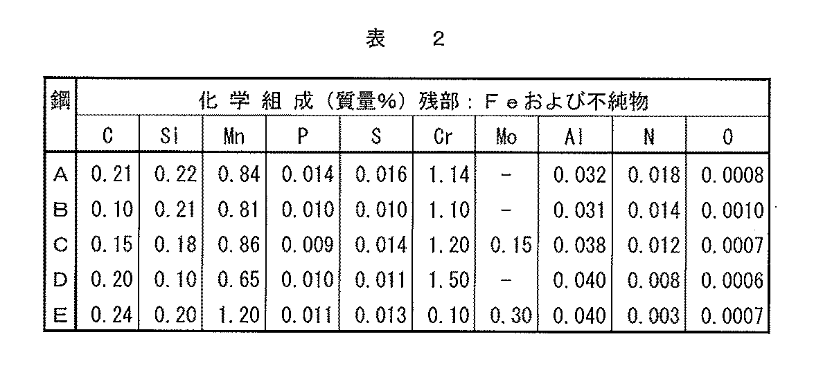
- steels A to E having chemical compositions shown in Table 2 were melted in a vacuum furnace to produce a 150 kg steel ingot.
- Steel A in Table 2 is a reprint of Steel A in Table 1 above.
- the steel ingots described above were heated to 1250 ° C. and then hot forged into round bars with a diameter of 30 mm. Cooling after hot forging was allowed to cool in the atmosphere.
- the above-mentioned round bar with a diameter of 30 mm obtained by hot forging was subjected to a normalizing treatment in which it was kept at a heating temperature of 900 ° C. for 60 minutes and then allowed to cool in the atmosphere.
- a rectangular parallelepiped having a cross section of 13 mm ⁇ 13 mm and a length of 100 mm was cut out from the center part of the round bar having a diameter of 30 mm subjected to the above normalization process. Thereafter, a semicircular notch with a radius of 2 mm was provided at a central portion in the length direction of one surface of the rectangular parallelepiped to prepare a four-point bending test piece.
- the above steels were subjected to carburizing treatment at a soaking temperature of 930 ° C. with respect to the four-point bending test pieces, and then put into 120 ° C. oil to perform “carburizing and quenching”. After performing the above-mentioned carburizing and quenching, it was further soaked at a heating temperature of 180 ° C. for 120 minutes, and then subjected to a tempering treatment that allowed to cool in the atmosphere.
- a “carburizing and tempering” treatment under general conditions was also performed on the 4-point bending test piece.
- the above four-point bending test piece was set at 930 ° C. with a carbon potential of 1.1% for 100 minutes and then with a carbon potential of 0.8% for 50 minutes. After heating, it was once cooled to 870 ° C. with the carbon potential kept at 0.8%, and kept at that temperature for 60 minutes for carburizing treatment, and then poured into 120 ° C. oil. After performing the above-mentioned carburizing and quenching, it was soaked at a heating temperature of 180 ° C. for 120 minutes, and then subjected to a tempering treatment that allowed to cool in the air.
- Table 3 shows the details of carburizing conditions. “Cp1” and “Cp2” in Table 3 represent “carbon potential” in the carburizing process. First, carburization is performed for the time indicated by “soaking time 1” under the condition of Cp1, and then “soaking” is performed under the condition of Cp2. Carburization was performed for the time indicated by “Time 2”. Test number 17 in Table 3 corresponds to the “carburizing and tempering” treatment under the above general conditions. In the carburizing conditions of this test number 17, the description of the above-described process of “cooling to 870 ° C. while maintaining the carbon potential at 0.8% and holding at that temperature for an additional 60 minutes” was omitted in Table 3.
- the hardness and carbon concentration distribution were investigated using the above-mentioned “carburized quenching and tempering” four-point bending test pieces.
- the hardness is a Vickers hardness (hereinafter also referred to as “HV hardness”) after embedding and polishing a four-point bending test piece in a resin so that a cross section at a portion provided with a semicircular notch can be investigated. ) was measured.
- the HV hardness test is performed by a method specified in JIS Z 2244 (2009) with a test force of 2.94 N, and the hardness of the central portion (hereinafter referred to as “central hardness”) and the hardness of the surface portion. (Hereinafter referred to as “surface hardness”).
- the center hardness was expressed as an average value obtained by measuring five points at a depth of 10 mm from the surface of the resin-embedded test piece with a semicircular notch constituting one side of the cross section.
- the surface hardness was expressed as an average value obtained by measuring five positions at a depth of 0.05 mm from the surface with the semicircular notch as a reference.
- Carbon concentration distribution was determined as follows. First, similarly to the above-described hardness measurement, a four-point bending test piece was embedded in a resin and polished so that a cross section at a portion provided with a semicircular notch could be investigated. Thereafter, with the notch bottom as the outermost surface, the carbon concentration distribution toward the center of the test piece was measured by a calibration curve using a wavelength dispersion type EPMA apparatus. Next, using the above measurement results, C (ave), which is an average carbon concentration from the outermost surface to the position of a depth of 0.2 mm from the outermost surface to the center, is obtained by the equation of “5 ⁇ ⁇ C (x) dx”. It was.
- Table 3 shows the surface hardness, center hardness, and C (ave) determined as described above.
- the bending fatigue strength is the bending fatigue strength of test No. 17 which is a representative example of a surface-hardened part (that is, using a steel A corresponding to SCr420, which is generally used as a case hardening steel, under the general conditions of “carburizing and quenching— Based on the bending fatigue strength of test No. 17 subjected to the bending fatigue test in the state of being “tempered”, the target was to improve it by 50% or more.
- Table 4 shows the above bending fatigue test results. Table 4 also shows the improvement rate from the value when the bending fatigue strength of test number 17 is used as a reference value.
- FIG. 1 shows the improvement rate of the bending fatigue strength when the bending fatigue strength of test number 17 is used as a reference value, and the average carbon concentration in mass% from the outermost surface to a position of a depth of 0.2 mm is C (ave). )
- the average carbon concentration from the outermost surface to a depth of 0.2 mm is mass% and is in the range of 0.35 to 0.60%, for example, shot peening treatment is performed to reduce the compressive residual stress.
- shot peening treatment is performed to reduce the compressive residual stress.
- the average carbon concentration of the hardened layer part where the fractured surface form of the hardened layer part is “brittle” is 0.45 to 0.60%, compressive residual stress is applied to the part surface by shot peening treatment or the like.
- brittle fracture can be suppressed and fatigue strength can be improved.
- the residual stress can be applied by shot peening
- the residual stress also has a distribution similar to the carbon concentration, and this residual stress distribution may vary depending on the processing conditions of shot peening.
- the shot peening treatment is usually applied to parts whose hardness of the hardened layer portion is 720 or more in HV hardness as represented by a carburized product having a carbon potential of about 0.8%. Done. For this reason, it is considered that the change in the surface roughness accompanying the shot peening process is not so problematic.
- the value of C (ave) of 0.35 to 0.60% at the mass% of ⁇ 2> is higher than the average carbon concentration in the case of the carburizing process with the above carbon potential being about 0.8%. Low.
- the hardness of the hardened layer portion when C (ave) is 0.35 to 0.60% is the hardness of the hardened layer portion of a normal carburized product carburized at a carbon potential of about 0.8%. Therefore, when the shot peening treatment is performed to apply the compressive residual stress, it is considered that the change in the surface roughness becomes large.
- the present inventors further investigated and investigated the correlation between the fatigue strength in the “low to medium cycle range”, the compressive residual stress, and the surface roughness.
- the compressive residual stress is polished from the surface to a predetermined depth position by electrolytic polishing, the intensity of diffracted X-rays is measured at each depth position, and the half width of the peak intensity obtained by the measurement and the peak center position It was calculated from the relationship.
- Table 5 shows the results of the above residual stress investigation.
- depth the depth from the outermost surface
- the residual stress is ⁇ r (y).
- Ir ⁇
- the residual stress intensity index Ir represented by the formula
- the residual stress intensity index Ir can be determined by the following methods (1) to (8), for example.
- (1) The outermost surface of the target test piece is set to 0 ⁇ m which is the reference position.
- (3) The compressive residual stress at the site of depth y (1) ⁇ m is measured using X-rays. This compressive residual stress measurement method using X-rays may be a general method.
- the surface is further polished by electrolytic polishing to a depth of y (2) ⁇ m.
- the electrolytic polishing is repeated up to a depth of 100 ⁇ m, and the compressive residual stress is measured at each depth of the electrolytically polished depth.
- the relationship between the obtained depth and compressive residual stress at a depth of 0 to 100 ⁇ m is plotted with the horizontal axis representing the depth and the vertical axis representing the absolute value of the compressive residual stress. Is obtained as a function (in other words, approximated by a curve).
- the residual stress intensity index Ir which is the integral of the absolute value of the compressive residual stress can be obtained. .
- Ir shown in Table 5 is a value obtained by measuring the compressive residual stress at each position of depth 0 ⁇ m, 10 ⁇ m, 30 ⁇ m, 50 ⁇ m, 80 ⁇ m, and 100 ⁇ m in the methods shown in the above (1) to (8). is there.
- the surface roughness of the specimen may be considered as a cause of the decrease in the bending fatigue strength improvement rate.
- the surface roughness of the test piece has an effect on the occurrence of fatigue cracks, and when the surface roughness of the parts is rough, fatigue cracks are easily generated by the “notch effect”, and therefore the fatigue strength is reduced. It is thought that it fell.
- Table 6 shows the above Rz measurement results. Table 6 shows the “bending fatigue strength improvement rate” in Table 4 and “ ⁇ r (0)”, “ ⁇ r (100)”, and “residual stress strength index Ir” in Table 5.
- the present invention has been completed based on the above findings, and the gist of the present invention is a carburized part shown in the following (1) to (3) and a method of manufacturing a carburized part shown in (4).
- Carburized parts made of steel in which the material steel is C: 0.15-0.25%, Si: 0.03-0.50%, Mn: 0.60% in mass%. 1.5% or less, P: 0.015% or less, S: 0.006 to 0.030%, Cr: 0.05 to 2.0%, Al: 0.10% or less, N: 0.0.
- the steel is a steel having a chemical composition composed of 03% or less and O: 0.0020% or less, the balance being Fe and impurities, and the surface hardened layer portion satisfying the following conditions (a) to (c) Features carburized parts.
- the integration interval that is, the range of “x” is 0 to 0.2 (mm).
- Rz refers to “maximum height roughness” defined in JIS B 0601 (2001).
- ⁇ r (0) indicates the compressive residual stress at the outermost surface of the component
- ⁇ r (100) indicates the compressive residual stress at a position of 100 ⁇ m from the outermost surface of the component.
- the integration interval that is, the range of “y” is 0 to 100 ( ⁇ m).
- the dough steel is replaced by a part of Fe as a balance, and is in mass%, Mo: less than 0.50%, Cu: 1.0% or less, Ni: 3.0% or less, and B: 0
- the carburized part according to (1) above which is a steel having a chemical composition including one or more selected from 0030% or less.
- the dough steel is replaced by a part of Fe as the balance, and is selected from mass%, Ti: 0.10% or less, Nb: 0.10% or less, and V: 0.30% or less.
- First stage shot peening process conditions ⁇ HV hardness of the projection material: 650 to 750, ⁇ Average particle diameter of the projection material: 0.6 to 1.0 mm, ⁇ Coverage: 500% or more
- Second stage shot peening treatment conditions ⁇ HV hardness of the projection material: 700 to 850, -Average particle size of the projection material: 0.05 to 0.25 mm, ⁇ Coverage: 500% or more.
- impurities in the “Fe and impurities” as the remainder in this specification refers to those mixed from ores, scraps, etc. as raw materials or the environment when industrially producing steel materials.
- the fatigue strength in the “low to medium cycle range” of the carburized parts of the present invention is significantly improved as compared with that of the conventional carburized and quenched / tempered parts.
- the carburized parts of the present invention are suitable for use as various shafts or power transmission parts for automobiles, construction machines, industrial machines, etc. that are shocking and may be subjected to relatively large loads.
- the improvement rate of the bending fatigue strength when the bending fatigue strength of test number 17 in Table 3 is used as a reference value is arranged by C (ave) which is an average carbon concentration in mass% from the outermost surface to a depth of 0.2 mm.
- C (ave) is an average carbon concentration in mass% from the outermost surface to a depth of 0.2 mm.
- the center hardness of the components also affects the fatigue strength.
- the center hardness of the components is preferably 350 or more in terms of HV hardness. Therefore, the lower limit of the C content is preferably 0.20%.
- the upper limit of the C content is preferably 0.24%.
- Si 0.03-0.50%
- Si is a deoxidizing element, and is an element having a so-called “temper softening resistance” action that suppresses a decrease in hardness when the martensite structure is tempered.
- the Si content is set to 0.03 to 0.50%.
- the lower limit of the Si content is preferably 0.08%.
- the upper limit of the Si content is preferably 0.35%.
- Mn Over 0.60% and 1.5% or less Mn is an element effective for improving hardenability. Furthermore, Mn has the effect of increasing the amount of retained austenite in the hardened layer part after carburizing treatment. In particular, when the content of Mn exceeds 0.60%, residual austenite is added to the hardened layer part after carburizing treatment. Form. For this reason, when compressive residual stress is applied by shot peening, the compressive residual stress can be introduced deeply and stably. However, even if Mn is contained in excess of 1.5%, in addition to saturation of the above effects, excessive austenite is formed, resulting in rough surface roughness after shot peening. In addition, the cost increases. Therefore, the Mn content is set to more than 0.60% and 1.5% or less. When applying compressive residual stress by shot peening treatment, in order to introduce the compressive residual stress deeper and more stably, it is particularly preferable that the lower limit of the Mn content is 0.70%. The upper limit is preferably 1.20%.
- P 0.015% or less P deteriorates the toughness of the hardened layer at the time of quenching.
- the content of P is set to 0.015% or less.
- the P content is preferably 0.010% or less.
- S 0.006 to 0.030%
- S combines with Mn to form MnS, and has an effect of improving machinability, in particular, chip disposal.
- the S content is less than 0.006%, it is difficult to obtain such an effect.
- the fatigue strength is reduced.
- the content of S exceeds 0.030%, fatigue is caused. The strength is significantly reduced. Therefore, the S content is set to 0.006 to 0.030%.
- the lower limit of the S content is preferably 0.008%.
- the upper limit of the S content is preferably 0.020%.
- Cr 0.05-2.0% Cr has the effect of improving the hardenability of the steel. Since Cr combines with C during surface hardening treatment such as carburizing treatment to form a composite carbide, it also has an effect of improving wear resistance. In order to reliably obtain these effects, Cr needs to be contained in an amount of 0.05% or more. However, when the Cr content exceeds 2.0%, the toughness deteriorates. Therefore, the Cr content is set to 0.05 to 2.0%. The lower limit of the Cr content is preferably 0.10%. The upper limit of the Cr content is preferably 1.85%.
- Al 0.10% or less
- Al has an effect of stabilizing and homogenizing deoxidation of steel. However, if its content exceeds 0.10%, the toughness deteriorates in addition to the saturation of the above effects. Therefore, the Al content is set to 0.10% or less.
- the Al content is preferably 0.08% or less, more preferably 0.05% or less.
- the preferable lower limit of the Al content is 0.005%. If at least 0.005% Al is contained, the deoxidation stabilization and homogenization effects are sufficient.
- N 0.03% or less N is dissolved in steel, and when the amount of dissolved N increases, the hot deformability decreases. Therefore, the N content is set to 0.03% or less. The N content is preferably reduced as much as possible.
- O oxygen
- oxygen is present as an impurity in steel and combines with elements in the steel to form an oxide, resulting in a decrease in strength, particularly a decrease in fatigue strength.
- the content of O is set to 0.0020% or less.
- the O content is preferably 0.0015% or less.
- One of the steels of the carburized part of the present invention has a chemical composition in which the balance is composed of Fe and impurities in addition to the above elements.
- Another one of the steels of the carburized part of the present invention is Mo, Cu, Ni, B, Ti, Nb and V, instead of a part of Fe in the “Fe and impurities” as the remainder. It has a chemical composition containing one or more selected elements.
- Mo, Cu, Ni and B have the effect of improving hardenability. For this reason, when it is desired to ensure greater hardenability, these elements may be contained.
- Mo, Cu, Ni, and B will be described.
- Mo Less than 0.50% Mo is an element effective for improving the hardenability of steel. Mo is also an element effective for improving the surface fatigue strength by suppressing the formation of grain boundary cementite that causes grain boundary embrittlement and increasing the resistance to temper softening. However, even if Mo is contained in an amount of 0.50% or more, the above effect is saturated and the cost is increased. For this reason, when Mo is contained, the amount is set to less than 0.50%.
- the upper limit of the Mo content is preferably 0.35%.
- the lower limit of the Mo content is preferably 0.10%.
- Cu 1.0% or less Cu has an effect of improving hardenability. Therefore, Cu may be contained to obtain this effect. However, when the Cu content exceeds 1.0%, the hot workability is deteriorated. Therefore, when Cu is contained, the amount is set to 1.0% or less.
- the Cu content is preferably 0.50% or less.
- the lower limit of the Cu content is preferably 0.05%, and more preferably 0.10%.
- Ni 3.0% or less Ni has an effect of improving hardenability. Therefore, Ni may be contained to obtain this effect. However, even if Ni is contained in an amount exceeding 3.0%, the above effect is saturated and the cost is increased. Therefore, when Ni is contained, the amount is set to 3.0% or less.
- the Ni content is preferably 2.0% or less.
- the lower limit of the Ni content is preferably 0.05%, and more preferably 0.10%.
- B 0.0030% or less B has an effect of improving hardenability. B also has the effect of suppressing the segregation of P and S at the austenite grain boundaries during quenching. Therefore, you may contain B in order to acquire such an effect. However, even if B is contained in an amount exceeding 0.0030%, the above effect is saturated and the cost is increased. Therefore, when B is contained, the amount is set to 0.0030% or less.
- the B content is preferably 0.0020% or less.
- the lower limit of the B content is preferably 0.0005%, and more preferably 0.0010%.
- the above-mentioned Mo, Cu, Ni and B can be contained alone or in combination of two or more.
- the total content of these elements may be less than 4.5030%, but is preferably 4.0% or less.
- Ti, Nb, and V have a function of refining crystal grains. For this reason, when it is desired to ensure this effect, these elements may be contained.
- Ti, Nb, and V will be described.
- Ti 0.10% or less Ti has an effect of refining crystal grains. That is, Ti combines with C or N in steel to form carbides, nitrides or carbonitrides, and has the effect of refining crystal grains during quenching. Therefore, Ti may be contained to obtain this effect. However, when Ti is contained in an amount exceeding 0.10%, the effect of refining crystal grains and the effect of fixing N can be obtained, but the toughness is lowered. Therefore, when Ti is contained, the amount is made 0.10% or less.
- the Ti content is preferably 0.08% or less.
- the lower limit of the Ti content is preferably 0.010%, and more preferably 0.015%.
- Nb 0.10% or less
- Nb has an effect of refining crystal grains. That is, Nb combines with C or N in steel to form carbides, nitrides or carbonitrides, and has the effect of refining crystal grains. Nb also has the effect of improving the strength of the steel. Therefore, Nb may be contained to obtain these effects. However, even if Nb in an amount exceeding 0.10% is contained, the above-described effect is saturated, resulting in an increase in cost and a reduction in toughness. Therefore, when Nb is contained, the amount is set to 0.10% or less.
- the Nb content is preferably 0.08% or less.
- the lower limit of the Nb content is preferably 0.01%, and more preferably 0.015%.
- V 0.30% or less
- V has an effect of refining crystal grains. That is, V combines with C or N in steel to form carbides, nitrides or carbonitrides, and has the effect of refining crystal grains. V also has the effect of improving the strength of the steel. Therefore, V may be contained in order to obtain these effects. However, even if V is contained in an amount exceeding 0.30%, the above-described effect is saturated, resulting in an increase in cost, and further a decrease in toughness. Therefore, when V is contained, the amount is set to 0.30% or less.
- the V content is preferably 0.25% or less.
- the lower limit of the V content is preferably 0.005%, and more preferably 0.010%.
- the above Ti, Nb and V can be contained in only one of them, or in a combination of two or more.
- the total content of these elements may be 0.50% or less, but is preferably 0.40% or less.
- C (ave) The carbon concentration in the hardened layer on the surface of the carburized part greatly affects the fatigue strength.
- C (ave) which is an average carbon concentration from the outermost surface to a position having a depth of 0.2 mm, is less than 0.35%, brittle fracture does not occur but fatigue strength is low, whereas 0.60% If it exceeds V, brittle fracture occurs, and it is difficult to improve fatigue strength even when compressive residual stress is applied. Therefore, C (ave) is set to 0.35 to 0.60%.
- the lower limit of C (ave) is preferably 0.38%.
- the upper limit of C (ave) is preferably 0.58%.
- (B) Surface roughness Rz The surface roughness of the carburized part affects the occurrence of fatigue cracks. When the surface roughness of the part is rough, fatigue cracks are easily generated due to the “notch effect”, and the fatigue strength is reduced. In particular, when Rz, which is the “maximum height roughness” specified in JIS B 0601 (2001), exceeds 15 ⁇ m in the “low to medium cycle range”, the notch effect becomes prominent and fatigue strength is improved. I can't let you. Therefore, the surface roughness Rz is set to 15 ⁇ m or less.
- the upper limit of Rz is preferably 13 ⁇ m. If Rz is smaller than 2.0 ⁇ m, the risk of seizure during sliding increases. For this reason, the lower limit of Rz is preferably 2.0 ⁇ m.
- the upper limit of ⁇ r (0) is preferably ⁇ 850 MPa.
- the upper limit of ⁇ r (100) is preferably ⁇ 850 MPa.
- the lower limit of the residual stress intensity index Ir is preferably 82000.
- the residual stress strength index Ir represented by the formula is an integral value of the compressive residual stress contributing to the improvement of the fatigue strength, and the larger the residual stress strength index, the greater the rate at which the fatigue strength is improved. For this reason, the upper limit of the residual stress intensity index Ir is not particularly defined.
- the carburized parts according to the present invention are described in the following steps (a) and (b), for example, in parts molded into a desired shape using the steel having the chemical composition of the dough described in (A). It can manufacture by performing these processes in order.
- step (C-1) Carburizing and quenching” process or “Carburizing and quenching-tempering” process in step (a): In the step (a), by carburizing in an atmosphere having a carbon potential of 0.35 to 0.90%, the average carbon concentration from the outermost surface of the part to a position at a depth of 0.2 mm is 0. After adjusting to 35 to 0.60%, quenching is performed, or after the quenching, further tempering is performed at a temperature of 200 ° C. or lower.
- C (a) which is the “carburizing and quenching” process or the “carburizing and quenching-tempering” process
- C (ave) which is an average carbon concentration from the outermost surface as a property of the hardened layer portion on the surface of the item (B) to a position at a depth of 0.2 mm
- C (ave) is easily set to 0.35. It is possible to adjust to ⁇ 0.60%.
- the carburizing treatment in the above atmosphere may be performed, for example, at a temperature of 890 to 950 ° C. and a soaking time of 120 to 300 min.
- the preferable lower limit of the temperature in the tempering process is 100 ° C. By setting it as 100 degreeC or more, after a low concentration carburizing hardening, the phenomenon (placement crack) which breaks after a time can fully be prevented.
- Shot peening as one means for imparting compressive residual stress to the surface hardened layer portion of the carburized component is a two-stage shot peening process of step (b), that is, First stage shot peening process conditions: ⁇ HV hardness of the projection material: 650 to 750, ⁇ Average particle diameter of the projection material: 0.6 to 1.0 mm, ⁇ Coverage: 500% or more Second stage shot peening treatment conditions: ⁇ HV hardness of the projection material: 700 to 850, -Average particle size of the projection material: 0.05 to 0.25 mm, ⁇ Coverage: 500% or more As good as to do.
- the hardened layer portion on the surface of the carburized part of the present invention has a C (ave) of 0.35 to 0.60% as described above, the hardness of the hardened surface portion is lower than that of the conventional carburized part. ing.
- Shot peening which is one means for imparting compressive residual stress, is applied to the conventional carburized component, that is, the hardness of the hardened layer portion is lower than that of the conventional carburized component.
- the compression residual stress can be applied by using a hard projection material (hereinafter also referred to as “shot sphere”), The conditions of the hardened layer portion on the surface of the item (B) that simultaneously satisfy all the conditions of ⁇ r (0): ⁇ 800 MPa or less, ⁇ r (100): ⁇ 800 MPa or less, and the residual stress intensity index Ir: 80000 or more. difficult.
- the surface roughness Rz of the component may increase and exceed 15 ⁇ m, the “low / medium cycle fatigue strength” that is the object of the present invention cannot be improved, but may be reduced.
- the first stage shot peening process in the two-stage shot peening process of the step (b) is mainly performed by plastically deforming the surface hardened layer of the carburized part to a deep position, and the characteristics of the hardened layer portion on the surface of the item (B).
- the following three conditions are satisfied simultaneously: ⁇ r (0): ⁇ 800 MPa or less, ⁇ r (100): ⁇ 800 MPa or less, and residual stress intensity index Ir: 80000 or more.
- the above shot peening process is ⁇ HV hardness of the projection material: 650 to 750, ⁇ Average particle diameter of the projection material: 0.6 to 1.0 mm, ⁇ Coverage: 500% or more It is better to implement as.
- the hardness of the projection material is preferably 650 to 750 in terms of HV hardness.
- the upper limit of the hardness of the projection material is more preferably 700 in terms of HV hardness.
- the lower limit of the hardness of the projection material is more preferably 680 in terms of HV hardness.
- the plastic deformation area formed when the shot sphere collides with the surface of the carburized part, that is, the depth from the outermost surface is affected by the average particle diameter of the shot sphere. Deep plastic deformation.
- the average particle diameter of shot spheres in the first-stage shot peening process is less than 0.6 mm, ⁇ r (100) may not be ⁇ 800 MPa or less.
- the average particle diameter of the shot sphere exceeds 1.0 mm the surface roughness Rz of the carburized component increases to exceed 15 ⁇ m, and a desired fatigue strength may not be obtained. Therefore, the average particle size of the projection material is preferably 0.6 to 1.0 mm.
- the upper limit of the average particle size of the projection material is more preferably 0.8 mm.
- the lower limit of the average particle diameter of the projection material is more preferably 0.65 mm.
- the coverage is preferably 500% or more.
- the lower limit of coverage is more preferably 550%. If the coverage is increased, the surface roughness Rz can be reduced, but the shot peening processing time increases. Therefore, from the viewpoint of productivity, the upper limit of coverage is preferably 700%.
- the coverage can be obtained from the ratio of the sum of the projection mark area (indentation area) of the projection material to the shot peened area of the carburized component.
- the coverage in one shot peening is C1
- the calculated value reaches about 98%, this is regarded as full coverage and is set to 100%.
- the coverage of 500% means a state in which the time for the coverage to reach 100% is five times.
- the first stage shot peening treatment is more preferably performed with an arc height of 0.30 to 0.60 mmN. This is because if the arc height is less than 0.30 mmN, the plastic deformation region of the carburized part surface becomes small, and compressive residual stress may not be applied to the desired depth, while the arc height is greater than 0.60 mmN. And although compressive residual stress can be applied to the deep position of the carburized part, the absolute value of the applied compressive residual stress may be small, and in any case, the desired fatigue strength may not be obtained Because.
- the lower limit of the arc height is more preferably 0.50 mmN.
- (C-2-2) Second stage shot peening process The second-stage shot peening process in the two-stage shot peening process of step (b) mainly uses the first stage shot peening process by using a projection material having an average particle size smaller than that of the first stage projection material. Compressive residual stress is applied in the vicinity of the extreme surface of the surface hardened layer of the carburized part, and ⁇ r (0): ⁇ 800 MPa or less, ⁇ r (100) as the characteristics of the hardened layer portion on the surface of the item (B) : -800 MPa or less and residual stress intensity index Ir: 80000 or more, and surface roughness Rz: 15 ⁇ m or less, in order to satisfy the conditions at the same time in a stable and reliable manner.
- the above shot peening process is ⁇ HV hardness of the projection material: 700 to 850, -Average particle size of the projection material: 0.05 to 0.25 mm, ⁇ Coverage: 500% or more It is better to implement as.
- the hardness of the projection material in the second stage shot peening process is preferably 700 to 850 in terms of HV hardness.
- the upper limit of the hardness of the projection material is more preferably 800 in terms of HV hardness.
- the lower limit of the hardness of the projection material is more preferably 720 in terms of HV hardness.
- the average particle diameter of the shot spheres In order to impart a desired compressive residual stress in the second stage shot peening process, it is preferable to reduce the average particle diameter of the shot spheres, contrary to the first stage shot peening process.
- the average particle diameter of the shot sphere is less than 0.05 mm, it may be difficult to cause plastic deformation in the surface layer portion of the carburized part, and a desired compressive residual stress may not be applied.
- the average particle diameter of the shot sphere exceeds 0.25 mm, the surface roughness Rz of the carburized component may increase and exceed 15 ⁇ m. Therefore, the average particle diameter of the projection material in the second stage shot peening process is preferably 0.05 to 0.25 mm.
- the upper limit of the average particle diameter of the projection material is more preferably 0.15 mm.
- the lower limit of the average particle diameter of the projection material is more preferably 0.08 mm.
- the coverage in the second-stage shot peening process is also preferably 500% or more.
- the lower limit of coverage is more preferably 550%. Increasing the coverage can reduce the surface roughness Rz, but increases the shot peening processing time. For this reason, from the viewpoint of productivity, the upper limit of coverage is preferably 700%.
- the coverage of 500% means that the time for the coverage to reach 100% has been multiplied by five.
- the second stage shot peening treatment is performed with an arc height of 0.20 to 0.40 mmN.
- the arc height is less than 0.20 mmN, the plastic deformation region on the surface of the carburized part becomes small and compression residual stress may not be applied to a desired depth, whereas the arc height is less than 0.40 mmN.
- the lower limit of the arc height is more preferably 0.25 mmN.
- the upper limit of the arc height is more preferably 0.35 mmN.
- Steel A and Steels F to K in Table 7 are steels whose chemical compositions are within the range defined by the present invention.
- Steels L to M are comparative steels in which any of the components is out of the content range defined in the present invention.
- Steel A is a steel corresponding to SCr420 described in JIS G 4053 (2008), and steel A in Table 1 is listed again.
- the steel ingots described above were heated to 1250 ° C. and then hot forged into round bars with a diameter of 30 mm. Cooling after hot forging was allowed to cool in the atmosphere.
- the above-mentioned round bar with a diameter of 30 mm obtained by hot forging was subjected to a normalizing treatment in which it was kept at a heating temperature of 900 ° C. for 60 minutes and then allowed to cool in the atmosphere.
- a rectangular parallelepiped having a cross section of 13 mm ⁇ 13 mm and a length of 100 mm is cut out from the central portion of the round rod having a diameter of 30 mm, which has been subjected to the normalization treatment, and then further in the longitudinal center of one surface of the rectangular parallelepiped.
- a four-point bending test piece was prepared by providing a semicircular notch with a radius of 2 mm at the site.
- the above steels were subjected to carburizing treatment with a soaking temperature of 930 ° C. on the four-point bending test piece as “carburizing and quenching”, and then poured into 120 ° C. oil. After performing the above-mentioned carburizing and quenching, it was further soaked at a heating temperature of 180 ° C. for 120 minutes, and then subjected to a tempering treatment that allowed to cool in the atmosphere.
- Table 8 shows the details of carburizing conditions. “Cp1” and “Cp2” in Table 8 represent “carbon potential” in the carburizing process. First, carburizing is performed for the time indicated by “soaking time 1” under the condition of Cp1, and then “soaking time 2” under the condition of Cp2. Carburization was performed for the time shown in FIG.
- Table 8 shows the treatment of test No. 17 in Table 3 above, which was performed on Steel A under the general “carburizing and tempering” conditions. Also in Table 8, the treatment of Test No. 17 is the same as in the case of Table 3 described above: “Cooling to 870 ° C. with the carbon potential kept at 0.8% and holding at that temperature for another 60 minutes” Description is omitted.
- the hardness and carbon concentration distribution were investigated using the above-mentioned “carburized quenching and tempering” four-point bending test pieces.
- the hardness was measured by embedding a 4-point bending test piece in a resin so that the cross section at the site where the semicircular notch was provided could be investigated, and then measuring the HV hardness.
- the HV hardness test was performed by a method specified in JIS Z 2244 (2009) with a test force of 2.94 N, and the center hardness and surface hardness were determined.
- the center hardness was expressed as an average value obtained by measuring five points at a depth of 10 mm from the surface of the resin-embedded test piece with a semicircular notch constituting one side of the cross section. .
- the surface hardness was expressed as an average value obtained by measuring five positions at a depth of 0.05 mm from the surface with the semicircular notch as a reference.
- Carbon concentration distribution was determined as follows. First, similarly to the above-described hardness measurement, a four-point bending test piece was embedded in a resin and polished so that a cross section at a portion provided with a semicircular notch could be investigated. Thereafter, with the notch bottom as the outermost surface, the carbon concentration distribution toward the center of the test piece was measured by a calibration curve using a wavelength dispersion type EPMA apparatus. Next, using the above measurement results, C (ave), which is an average carbon concentration from the outermost surface to the position of a depth of 0.2 mm from the outermost surface to the center, is obtained by the equation of “5 ⁇ ⁇ C (x) dx”. It was.
- Table 8 shows the surface hardness, center hardness and C (ave) determined as described above.
- test specimens 17 to 30 and the test numbers 33 to 41 shown in Table 8 that were subjected to the “carburization quenching and tempering” treatment the conditions shown in Table 9 were applied to the surface provided with the semicircle notch. Then, a two-stage shot peening process was performed.
- the residual stress intensity index Ir was obtained by measuring the compressive residual stress at each of the depths of 0 ⁇ m, 10 ⁇ m, 30 ⁇ m, 50 ⁇ m, 80 ⁇ m, and 100 ⁇ m in the method described in (1) to (8).
- the bending fatigue strength is the same as that of the test No. 17, ie, with the steel A corresponding to SCr420 generally used as the case-hardened steel being subjected to the “carburizing and tempering” treatment under the general conditions. Based on the bending fatigue strength when subjected to a bending fatigue test, the goal was to improve it by 50% or more.
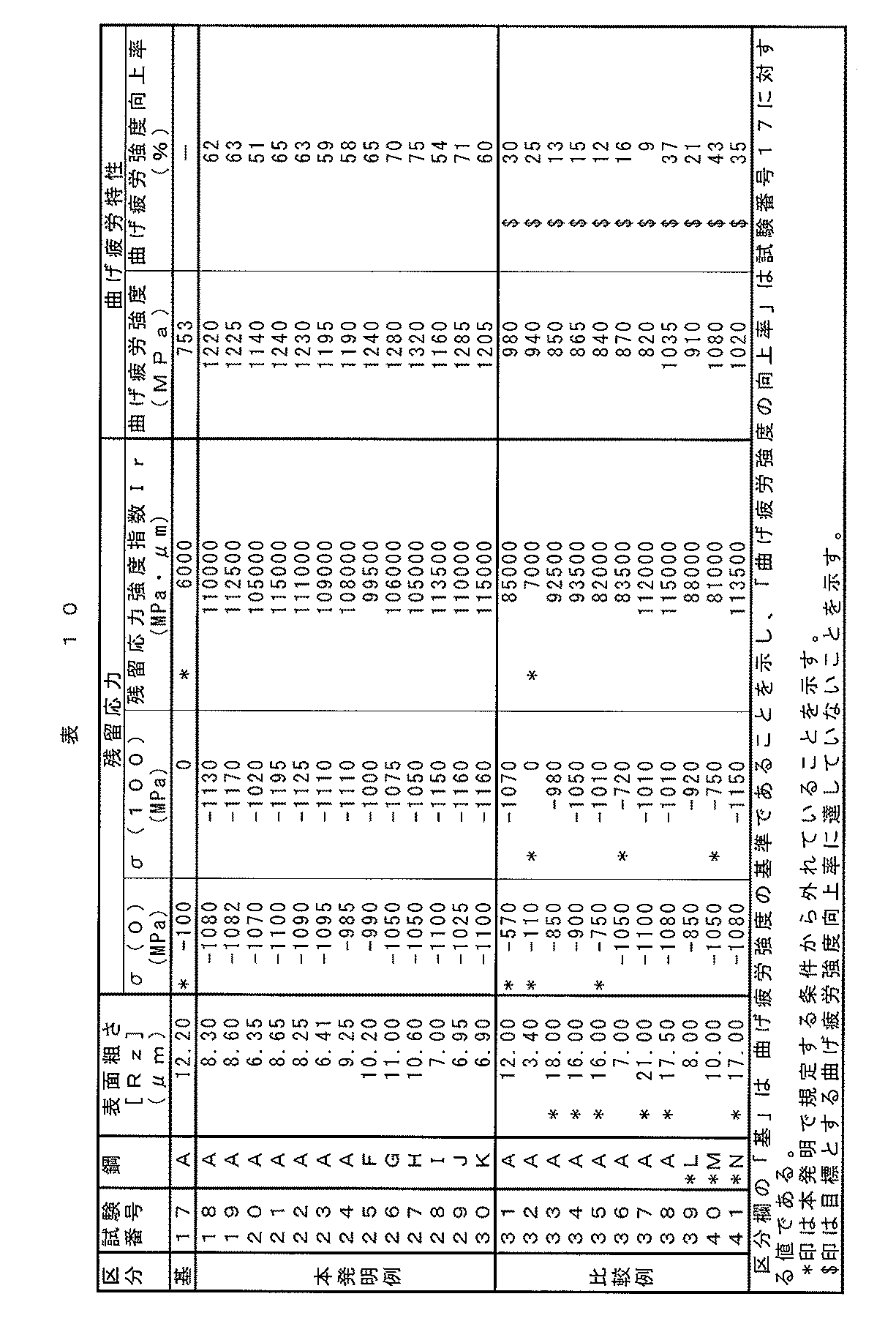
- Table 10 summarizes the above test results. Table 10 shows the test results for test number 17 shown in Table 6 above. The improvement rate from the value when the bending fatigue strength of Test No. 17 is used as a reference value is also shown.
- the bending fatigue strength in the case of test numbers 18 to 30 that satisfy the conditions specified in the present invention is carburized under conventional general conditions using steel A corresponding to SCr420, which is general as case hardening steel.
- the bending fatigue strength of the quenched and tempered test No. 17 is improved by 50% or more, and the fatigue strength in the “low to medium cycle range” is greatly improved compared to that of the conventional carburized and quenched and tempered parts. Is clear.
- ⁇ (0) is ⁇ 570 MPa, which is larger than the upper limit value ⁇ 800 MPa defined in the present invention. For this reason, the improvement of the target fatigue strength was not recognized.
- both the values of ⁇ (0) and ⁇ (100), which are residual stresses, are larger than the upper limit value ⁇ 800 MPa defined in the present invention, and the residual stress strength index Ir is 7000. It is smaller than the lower limit of 80000 defined in the present invention. For this reason, the improvement of the target fatigue strength was not recognized.
- the surface roughness Rz is 18.00 ⁇ m, 16.00 ⁇ m, 21.00 ⁇ m and 17.50 ⁇ m, respectively, and the upper limit values specified in the present invention. Greater than. For this reason, in any case, improvement of fatigue strength was not observed.
- the surface roughness Rz is as large as 16.00 ⁇ m, and the value of the residual stress ⁇ (0) is ⁇ 750 MPa, which is larger than the upper limit value ⁇ 800 MPa defined in the present invention. For this reason, the improvement target of fatigue strength could not be achieved.
- the value of the residual stress ⁇ (100) is ⁇ 720 MPa, which is larger than the upper limit value ⁇ 800 MPa defined in the present invention. For this reason, the target fatigue strength was not reached.
- the Mn content of steel M is 0.30%, which is below the conditions specified in the present invention, so the value of residual stress ⁇ (100) is ⁇ 750 MPa, which is the upper limit value ⁇ 800 MPa specified in the present invention. Becomes too large to secure a sufficient compressive residual stress in a deep part. For this reason, the target fatigue strength was not reached.
- the fatigue strength in the “low to medium cycle range” of the carburized parts of the present invention is significantly improved as compared with that of the conventional carburized and quenched / tempered parts.
- the carburized parts of the present invention are suitable for use as various shafts or power transmission parts for automobiles, construction machines, industrial machines, etc. that are shocking and may be subjected to relatively large loads.
Landscapes
- Chemical & Material Sciences (AREA)
- Engineering & Computer Science (AREA)
- Materials Engineering (AREA)
- Mechanical Engineering (AREA)
- Metallurgy (AREA)
- Organic Chemistry (AREA)
- Crystallography & Structural Chemistry (AREA)
- Physics & Mathematics (AREA)
- Thermal Sciences (AREA)
- Chemical Kinetics & Catalysis (AREA)
- Heat Treatment Of Articles (AREA)
- Solid-Phase Diffusion Into Metallic Material Surfaces (AREA)
Abstract
Description

C(ave)={∫C(x)dx}/0.2=5×∫C(x)dx
の式で表される値を指す。上記の式において、積分区間、つまり「x」の範囲は、0~0.2(mm)である。

1段階目のショットピーニング処理条件:
・投射材:HV硬さ:700、平均粒径:0.6mm、
・投射時間:12s、
・投射エア圧力:0.35MPa、
・カバレージ:500%、
2段階目のショットピーニング処理条件:
・投射材:HV硬さ:800、平均粒径:0.1mm、
・投射時間:20s、
・投射エア圧力:0.2MPa、
・カバレージ:500%。
1段階目のショットピーニング処理条件:
・投射材:HV硬さ:780、平均粒径:1.2mm、
・投射時間:10s、
・投射エア圧力:0.35MPa、
・カバレージ:500%、
2段階目のショットピーニング処理条件:
・投射材:HV硬さ:800、平均粒径:0.1mm、
・投射時間:8s、
・投射エア圧力:0.2MPa、
・カバレージ:200%。
・応力比:0.1、
・支点間距離:45mm、
・試験周波数:5Hz、
の条件で4点曲げ疲労試験を行った。

Ir=∫|σr(y)|dy
の式で表される残留応力強度指数Irを併せて示した。
(1)対象となる試験片の最表面を基準位置である0μmとする。
(2)電解研磨によって、深さy(1)μmの位置まで研磨する。
(3)深さy(1)μmの部位における圧縮残留応力をX線を用いて測定する。このX線による圧縮残留応力測定方法は、一般的な方法で良い。
(4)次に、再度電解研磨によって、深さy(2)μmの位置まで研磨する。
(5)上記(3)と同様にして、深さy(2)μmの部位における圧縮残留応力を測定する。
(6)深さ100μmの位置まで、上記の電解研磨を繰り返し、電解研磨した各深さの部位における圧縮残留応力を測定する。
(7)深さ0~100μmの位置について、得られた深さと圧縮残留応力の関係を、横軸に深さ、縦軸に圧縮残留応力の絶対値をとってプロットし、深さと圧縮残留応力の絶対値との関係を関数として求める(換言すれば、曲線で近似する)。
(8)上記(7)で得られた曲線が縦軸と横軸で挟まれた部分の面積を算出すれば、圧縮残留応力の絶対値の積分である残留応力強度指数Irを求めることができる。


(a)C(ave):質量%で0.35~0.60%、
(b)表面粗さRz:15μm以下、ならびに、
(c)σr(0):-800MPa以下、σr(100):-800MPa以下および残留応力強度指数Ir:80000以上。
1段階目のショットピーニング処理条件:
・投射材のHV硬さ:650~750、
・投射材の平均粒径:0.6~1.0mm、
・カバレージ:500%以上、
2段階目のショットピーニング処理条件:
・投射材のHV硬さ:700~850、
・投射材の平均粒径:0.05~0.25mm、
・カバレージ:500%以上。
C:0.15~0.25%
Cは、鋼の強度を確保する作用および浸炭焼入れ後の硬化層硬さを確保する作用を有する。しかしながら、浸炭処理を前提とした場合、その含有量が0.15%未満では、自動車、建設機械、産業機械等の各種シャフト類あるいは動力伝達用部品等として用いるのに適した強度が得られない。一方、Cの含有量が0.25%を超えると、所定の形状に成形加工を行う際の被削性が低下する。したがって、Cの含有量を0.15~0.25%とした。
Siは、脱酸元素であり、さらに、マルテンサイト組織を焼戻し処理する際の硬さの低下を抑制する、いわゆる「焼戻し軟化抵抗」作用を有する元素である。しかしながら、その含有量が0.03%未満ではこうした効果を得難い。一方、Si含有量の増加に伴ってA3変態点が上昇し、脱炭および浸炭時の異常層が生じやすくなり、特に、その含有量が0.50%を超えると、脱炭および浸炭異常層の生成が顕著になる。したがって、Siの含有量を0.03~0.50%とした。Si含有量の下限は好ましくは0.08%である。Si含有量の上限は好ましくは0.35%である。
Mnは、焼入れ性を向上させるのに有効な元素である。さらに、Mnは、浸炭処理後の硬化層部の残留オーステナイト量を増大させる作用を有し、特に、Mnの含有量が0.60%を超えると、浸炭処理後の硬化層部に残留オーステナイトを形成する。このため、ショットピーニング処理によって圧縮残留応力を付与する場合、その圧縮残留応力を深く、かつ安定的に導入することができる。しかしながら、1.5%を超えてMnを含有させても前記の効果が飽和することに加えて、残留オーステナイトが過剰に生成することによりショットピーニング加工後の表面粗さが粗くなる。そのうえに、コストも嵩んでしまう。したがって、Mnの含有量を0.60%を超えて1.5%以下とした。圧縮残留応力をショットピーニング処理によって付与する場合、その圧縮残留応力をより深く、かつより安定的に導入するためには、特に、Mn含有量の下限を0.70%とすることが好ましく、その上限を1.20%とすることが好ましい。
Pは、焼入れ時の硬化層の靱性を劣化させ、特に、その含有量が0.015%を超えると、硬化層の靱性低下が著しくなる。したがって、Pの含有量を、0.015%以下とした。なお、Pの含有量は、0.010%以下にすることが好ましい。
Sは、Mnと結合してMnSを形成し、被削性、なかでも切り屑処理性を高める作用を有する。しかしながら、Sの含有量が0.006%未満では、こうした効果を得難い。一方、Sの含有量が多くなって形成されるMnSが多くなると、被削性は改善されても、疲労強度の低下を招き、特に、Sの含有量が0.030%を超えると、疲労強度の低下が著しくなる。したがって、Sの含有量を0.006~0.030%とした。S含有量の下限は好ましくは0.008%である。S含有量の上限は好ましくは0.020%である。
Crは、鋼の焼入れ性を向上させる効果がある。Crは、浸炭処理などの表面硬化処理時にCと結合して複合炭化物を形成するので、耐摩耗性を向上させる効果も有する。これらの効果を確実に得るには、Crは0.05%以上の含有量とする必要がある。しかしながら、Crの含有量が2.0%を超えると靱性が劣化する。したがって、Cr含有量を0.05~2.0%とした。Cr含有量の下限は好ましくは0.10%である。Cr含有量の上限は好ましくは1.85%である。
Alは、鋼の脱酸の安定化および均質化を図る作用を有する。しかしながら、その含有量が0.10%を超えると、前記効果が飽和することに加えて靱性が劣化するようになる。したがって、Alの含有量を0.10%以下とした。Alの含有量は、好ましくは、0.08%以下、より好ましくは0.05%以下である。
Nは、鋼中に固溶し、この固溶N量が増加すると、熱間変形能の低下をきたす。したがって、Nの含有量を、0.03%以下とした。Nの含有量は可能な限り低減することが好ましい。
O(酸素)は、鋼中に不純物として存在し、鋼中の元素と結合して酸化物を形成し、強度低下、なかでも疲労強度の低下を招く。特に、Oの含有量が0.0020%を超えると、形成される酸化物が多くなるとともにMnSが粗大化して、疲労強度の低下が顕著になる。したがって、Oの含有量を0.0020%以下とした。Oの含有量は0.0015%以下とすることが好ましい。
Moは、鋼の焼入れ性を向上させるのに有効な元素である。Moは、粒界脆化の原因となる粒界セメンタイトの生成抑制および焼戻し軟化抵抗を高めて、面疲労強度を向上させるのに有効な元素でもある。しかしながら、Moを0.50%以上含有させても、前記の効果は飽和し、コストが嵩むばかりである。このため、Moを含有させる場合、その量を0.50%未満とした。Mo含有量の上限は0.35%とすることが好ましい。
Cuは、焼入れ性を向上させる作用を有する。したがって、この効果を得るためにCuを含有してもよい。しかしながら、Cuの含有量が1.0%を超えると、熱間加工性を劣化させる。したがって、Cuを含有させる場合、その量を1.0%以下とした。Cuの含有量は0.50%以下とすることが好ましい。
Niは、焼入れ性を向上させる作用を有する。したがって、この効果を得るためにNiを含有してもよい。しかしながら、3.0%を超える量のNiを含有させても上記の効果は飽和し、コストが嵩むばかりである。したがって、Niを含有させる場合、その量を3.0%以下とした。Niの含有量は2.0%以下とすることが好ましい。
Bは、焼入れ性を向上させる作用を有する。Bには、焼入れ時のオーステナイト粒界におけるPおよびSの偏析を抑制する作用もある。したがって、こうした効果を得るためにBを含有してもよい。しかしながら、0.0030%を超える量のBを含有させても上記の効果は飽和し、コストが嵩むばかりである。したがって、Bを含有させる場合、その量を0.0030%以下とした。なお、Bの含有量は0.0020%以下とすることが好ましい。
Tiは、結晶粒を微細化させる作用を有する。すなわち、Tiは、鋼中のCあるいはNと結合して炭化物、窒化物あるいは炭窒化物を形成し、焼入れの際に結晶粒を微細化する作用を有する。したがって、この効果を得るためにTiを含有してもよい。しかしながら、0.10%を超える量のTiを含有させた場合、結晶粒の微細化効果およびNの固定効果は得られるが、靱性を低下させてしまう。したがって、Tiを含有させる場合、その量を0.10%以下とした。Tiの含有量は0.08%以下とすることが好ましい。
Nbは、結晶粒を微細化させる作用を有する。すなわち、Nbは、鋼中のCあるいはNと結合して炭化物、窒化物あるいは炭窒化物を形成し、結晶粒を微細化する作用を有する。Nbには、鋼の強度を向上させる作用もある。したがって、これらの効果を得るためにNbを含有してもよい。しかしながら、0.10%を超える量のNbを含有させても、前記の効果が飽和するのでコストが嵩むことになり、さらに、靱性の低下も生じる。したがって、Nbを含有させる場合、その量を0.10%以下とした。Nbの含有量は0.08%以下とすることが好ましい。
Vは、結晶粒を微細化させる作用を有する。すなわち、Vは、鋼中のCあるいはNと結合して炭化物、窒化物あるいは炭窒化物を形成し、結晶粒を微細化する作用を有する。Vには、鋼の強度を向上させる作用もある。したがって、これらの効果を得るためにVを含有してもよい。しかしながら、0.30%を超える量のVを含有させても、前記の効果が飽和するのでコストが嵩むことになり、さらに、靱性の低下も生じる。したがって、Vを含有させる場合、その量を0.30%以下とした。Vの含有量は0.25%以下とすることが好ましい。
生地の鋼が、前記(A)項で述べた化学組成を有する本発明の浸炭部品は、その表面の硬化層部が下記(a)~(c)の条件を満たすものでなければならない。
(b)表面粗さRz:15μm以下、
(c)σr(0):-800MPa以下、σr(100):-800MPa以下および残留応力強度指数Ir:80000以上。
浸炭部品の表面の硬化層部の炭素濃度は疲労強度に大きく影響を与える。最表面から深さ0.2mmの位置までの平均炭素濃度であるC(ave)が、0.35%未満の場合には、脆性破壊は生じないが疲労強度が低く、一方、0.60%を超えた場合には、脆性破壊が生じ、たとえ、圧縮残留応力が付与された場合でも、疲労強度を向上させることが困難である。したがって、C(ave)を0.35~0.60%とした。C(ave)の下限は好ましくは0.38%である。C(ave)の上限は好ましくは0.58%である。
浸炭部品の表面粗さは、疲労亀裂の発生に対して影響を及ぼす。部品の表面粗さが粗い場合には「切欠き効果」によって疲労亀裂が容易に発生し、このため疲労強度が低下する。特に、「低~中サイクル域」において、JIS B 0601(2001)に規定された「最大高さ粗さ」であるRzが15μmを超える場合は、切欠き効果が顕著になり、疲労強度を向上させることができない。したがって、表面粗さRzを15μm以下とした。Rzの上限は13μmとすることが好ましい。Rzが2.0μmより小さくなると、摺動の際に焼付きが生じる危険性が高くなる。このため、Rzの下限は2.0μmとすることが好ましい。
圧縮残留応力を部品表面に付与することによって、疲労強度を高めることができるものの、最表面から100μmの位置までの残留応力の分布状態が大きく影響する。
Ir=∫|σr(y)|dy
の式で表される残留応力強度指数Irは、疲労強度向上に寄与する圧縮残留応力の積分値であり、残留応力強度指数が大きいほど、疲労強度が向上する割合が大きくなる。このため、残留応力強度指数Irの上限も特に定めるものではない。
以下に詳述する製造条件は、工業的な規模で本発明の浸炭部品を経済的に要領よく実現するための方法の一つであり、浸炭部品自体の技術的範囲はこの製造条件によって規定されるものではない。
工程(a)では、炭素ポテンシャルが0.35~0.90%の雰囲気で浸炭処理することにより、部品の最表面から深さ0.2mmの位置までの平均炭素濃度が質量%で、0.35~0.60%となるように調整してから、焼入れ処理するか、あるいは、前記焼入れ処理の後、さらに、200℃以下の温度で焼戻し処理する。
浸炭部品の表面硬化層部に、圧縮残留応力を付与する1つの手段としてのショットピーニングは、工程(b)の2段階ショットピーニング処理、つまり、
1段階目のショットピーニング処理条件:
・投射材のHV硬さ:650~750、
・投射材の平均粒径:0.6~1.0mm、
・カバレージ:500%以上、
2段階目のショットピーニング処理条件:
・投射材のHV硬さ:700~850、
・投射材の平均粒径:0.05~0.25mm、
・カバレージ:500%以上、
として行うのがよい。
工程(b)の2段階ショットピーニング処理における1段階目のショットピーニング処理は、主に浸炭部品の表面硬化層を深い位置まで塑性変形させて、前記(B)項の表面の硬化層部の特性としての、σr(0):-800MPa以下、σr(100):-800MPa以下および残留応力強度指数Ir:80000以上という3条件を同時に満たすために行うものである。上記のショットピーニング処理は、
・投射材のHV硬さ:650~750、
・投射材の平均粒径:0.6~1.0mm、
・カバレージ:500%以上、
として実施するのがよい。
Cn=[1-(1-C1)n]×100
の式で表わされ、その算出値が98%程度になったとき、これをフルカバレージとみなし、100%とする。そして、カバレージ500%とはカバレージが100%に達する時間を5倍にした状態をいう。
工程(b)の2段階ショットピーニング処理における2段階目のショットピーニング処理は、1段階目の投射材よりも平均粒径が小さい投射材を用いることで、主に1段階目のショットピーニング処理を行った浸炭部品の表面硬化層の極表面近傍に圧縮残留応力を付与して、前記(B)項の表面の硬化層部の特性としての、σr(0):-800MPa以下、σr(100):-800MPa以下および残留応力強度指数Ir:80000以上という3条件、ならびに、表面粗さRz:15μm以下との条件を同時に、安定かつ確実に満たすために行うものである。上記のショットピーニング処理は、
・投射材のHV硬さ:700~850、
・投射材の平均粒径:0.05~0.25mm、
・カバレージ:500%以上、
として実施するのがよい。


・応力比:0.1、
・支点間距離:45mm、
・試験周波数:5Hz、
の条件で4点曲げ疲労試験を行った。
Claims (4)
- 鋼製の浸炭部品であって、
生地の鋼が、質量%で、
C:0.15~0.25%、
Si:0.03~0.50%、
Mn:0.60%を超えて1.5%以下、
P:0.015%以下、
S:0.006~0.030%、
Cr:0.05~2.0%、
Al:0.10%以下、
N:0.03%以下および
O:0.0020%以下
を含有し、残部がFeおよび不純物からなる化学組成を有する鋼であり、
表面硬化層部が下記(a)~(c)の条件を満たす、
ことを特徴とする浸炭部品。
(a)C(ave):質量%で0.35~0.60%、
(b)表面粗さRz:15μm以下、ならびに、
(c)σr(0):-800MPa以下、σr(100):-800MPa以下および残留応力強度指数Ir:80000以上。
ただし、
C(ave):最表面から深さ0.2mmの位置までの平均炭素濃度、
表面粗さRz:JIS B 0601(2001)に規定された最大高さ粗さ、
σr(0):部品の最表面における圧縮残留応力、
σr(100):部品の最表面から100μmの位置における圧縮残留応力、
残留応力強度指数Ir:部品の最表面から100μm深さまでの位置での最表面からの深さをyμm、その部位における残留応力をσr(y)として〔Ir=∫|σr(y)|dy〕で表される値を指す。ここで、積分区間、つまり「y」の範囲は、0~100(μm)である。 - 生地の鋼が、残部としてのFeの一部に代えて、質量%で、
Mo:0.50%未満、
Cu:1.0%以下、
Ni:3.0%以下および
B:0.0030%以下
のうちから選ばれる1種以上を含む化学組成を有する鋼であることを特徴とする請求項1に記載の浸炭部品。 - 生地の鋼が、残部としてのFeの一部に代えて、質量%で、
Ti:0.10%以下、
Nb:0.10%以下および
V:0.30%以下のうちから選ばれる1種以上を含む化学組成を有する鋼であることを特徴とする請求項1または2に記載の浸炭部品。 - 請求項1から3までのいずれかに記載の生地の化学組成を有する鋼を用いて所望の形状に成形加工された部品に、下記の工程(a)および(b)に記載の処理を順に施すことを特徴とする浸炭部品の製造方法。
工程(a):炭素ポテンシャルが0.35~0.90%の雰囲気で浸炭処理することにより、部品の最表面から深さ0.2mmの位置までの平均炭素濃度が質量%で、0.35~0.60%となるようにして焼入れ処理するか、あるいは、前記焼入れ処理の後、さらに、200℃以下の温度で焼戻し処理する。
工程(b):下記の条件を満たす2段階ショットピーニング処理を施す。
1段階目のショットピーニング処理条件:
・投射材のHV硬さ:650~750、
・投射材の平均粒径:0.6~1.0mm、
・カバレージ:500%以上、
2段階目のショットピーニング処理条件:
・投射材のHV硬さ:700~850、
・投射材の平均粒径:0.05~0.25mm、
・カバレージ:500%以上。
Priority Applications (6)
| Application Number | Priority Date | Filing Date | Title |
|---|---|---|---|
| EP10780562.4A EP2436795B1 (en) | 2009-05-27 | 2010-05-26 | Carburized component and manufacturing method therefor |
| KR1020117029169A KR101371929B1 (ko) | 2009-05-27 | 2010-05-26 | 침탄 부품 및 그 제조 방법 |
| CN2010800332609A CN102459678B (zh) | 2009-05-27 | 2010-05-26 | 渗碳部件及其制造方法 |
| PL10780562T PL2436795T3 (pl) | 2009-05-27 | 2010-05-26 | Nawęglony komponent i sposób jego produkcji |
| JP2011516033A JP5378512B2 (ja) | 2009-05-27 | 2010-05-26 | 浸炭部品およびその製造方法 |
| US13/304,733 US8961710B2 (en) | 2009-05-27 | 2011-11-28 | Carburized component and manufacturing method |
Applications Claiming Priority (2)
| Application Number | Priority Date | Filing Date | Title |
|---|---|---|---|
| JP2009127175 | 2009-05-27 | ||
| JP2009-127175 | 2009-05-27 |
Related Child Applications (1)
| Application Number | Title | Priority Date | Filing Date |
|---|---|---|---|
| US13/304,733 Continuation US8961710B2 (en) | 2009-05-27 | 2011-11-28 | Carburized component and manufacturing method |
Publications (1)
| Publication Number | Publication Date |
|---|---|
| WO2010137607A1 true WO2010137607A1 (ja) | 2010-12-02 |
Family
ID=43222714
Family Applications (1)
| Application Number | Title | Priority Date | Filing Date |
|---|---|---|---|
| PCT/JP2010/058876 Ceased WO2010137607A1 (ja) | 2009-05-27 | 2010-05-26 | 浸炭部品およびその製造方法 |
Country Status (7)
| Country | Link |
|---|---|
| US (1) | US8961710B2 (ja) |
| EP (1) | EP2436795B1 (ja) |
| JP (1) | JP5378512B2 (ja) |
| KR (1) | KR101371929B1 (ja) |
| CN (1) | CN102459678B (ja) |
| PL (1) | PL2436795T3 (ja) |
| WO (1) | WO2010137607A1 (ja) |
Cited By (6)
| Publication number | Priority date | Publication date | Assignee | Title |
|---|---|---|---|---|
| JP2012036475A (ja) * | 2010-08-10 | 2012-02-23 | Sanyo Special Steel Co Ltd | 水素環境下で長寿命である転動部品や歯車の製造方法 |
| JP2012139790A (ja) * | 2011-01-04 | 2012-07-26 | Sanyo Special Steel Co Ltd | 投射材の寿命に優れたショットピーニング方法 |
| WO2019123755A1 (ja) * | 2017-12-22 | 2019-06-27 | 新東工業株式会社 | ショットピーニング方法 |
| CN110964979A (zh) * | 2019-12-05 | 2020-04-07 | 邯郸钢铁集团有限责任公司 | 具有良好成型性能的自卸车厢体用耐磨钢及其生产方法 |
| JP2021155797A (ja) * | 2020-03-26 | 2021-10-07 | 大同特殊鋼株式会社 | 高強度部品及びその製造方法 |
| CN113481465A (zh) * | 2021-06-30 | 2021-10-08 | 中国航发动力股份有限公司 | 一种渗碳层制备及检测方法 |
Families Citing this family (34)
| Publication number | Priority date | Publication date | Assignee | Title |
|---|---|---|---|---|
| JP2013241961A (ja) * | 2012-05-18 | 2013-12-05 | Hino Motors Ltd | 歯車製造方法及び歯車 |
| WO2014034150A1 (ja) * | 2012-09-03 | 2014-03-06 | 新日鐵住金株式会社 | 浸炭部品 |
| JP6114616B2 (ja) * | 2013-04-08 | 2017-04-12 | 本田技研工業株式会社 | 浸炭部品、その製造方法及び浸炭部品用鋼 |
| JP2015086890A (ja) * | 2013-10-28 | 2015-05-07 | 中央発條株式会社 | ばね及びばねの製造方法 |
| CN103757551B (zh) * | 2013-12-12 | 2015-12-09 | 嵊州市特种链轮有限公司 | 一种机械传动链轮材料及制造方法 |
| KR101830017B1 (ko) * | 2013-12-27 | 2018-02-19 | 신닛테츠스미킨 카부시키카이샤 | 침탄 강 부품의 제조 방법 및 침탄 강 부품 |
| WO2016126456A1 (en) * | 2015-02-04 | 2016-08-11 | Sikorsky Aircraft Corporation | Methods and processes of forming gears |
| US11584969B2 (en) * | 2015-04-08 | 2023-02-21 | Metal Improvement Company, Llc | High fatigue strength components requiring areas of high hardness |
| US10619222B2 (en) * | 2015-04-08 | 2020-04-14 | Metal Improvement Company, Llc | High fatigue strength components requiring areas of high hardness |
| KR101705168B1 (ko) * | 2015-04-20 | 2017-02-10 | 현대자동차주식회사 | 내구성이 향상된 침탄 합금강 및 이의 제조방법 |
| WO2018056333A1 (ja) * | 2016-09-20 | 2018-03-29 | 新日鐵住金株式会社 | 浸炭シャフト部品 |
| CN106636567A (zh) * | 2016-10-19 | 2017-05-10 | 四川六合锻造股份有限公司 | 一种提高G20CrNiMoA淬透性能的方法 |
| CN107604253A (zh) * | 2017-08-30 | 2018-01-19 | 东风商用车有限公司 | 一种高淬透性Mn‑Cr系列渗碳钢 |
| CN109402498B (zh) * | 2018-08-29 | 2020-08-28 | 宝钢特钢韶关有限公司 | 一种高温渗碳齿轮钢及其制造方法 |
| JP7154073B2 (ja) | 2018-09-12 | 2022-10-17 | 大同特殊鋼株式会社 | 耐高面圧部品およびその製造方法 |
| KR102153196B1 (ko) * | 2018-12-18 | 2020-09-07 | 주식회사 포스코 | 고탄소 보론강 강재 및 그 제조방법 |
| CN109628834A (zh) * | 2018-12-29 | 2019-04-16 | 中国第汽车股份有限公司 | 一种重型变速器轴齿零件用高镍含铌高强度渗碳钢材料 |
| MX2021011756A (es) | 2019-03-29 | 2021-10-19 | Nippon Steel Corp | Parte carburada y metodo para fabricar la misma. |
| CN110218949A (zh) * | 2019-07-12 | 2019-09-10 | 东北大学 | 利用微合金化提高渗碳温度的方法和低碳钢的表面渗碳方法 |
| US11149832B2 (en) * | 2019-12-13 | 2021-10-19 | Aichi Steel Corporation | Differential hypoid gear, pinion gear, and paired hypoid gears formed by combination thereof |
| CN111286671B (zh) * | 2020-02-28 | 2021-06-29 | 江阴兴澄特种钢铁有限公司 | 一种超纯净高温细晶粒齿轮钢、制造方法及其应用 |
| JP7323850B2 (ja) * | 2020-06-26 | 2023-08-09 | 日本製鉄株式会社 | 鋼材及び浸炭鋼部品 |
| CN112030065B (zh) * | 2020-07-16 | 2021-08-03 | 钢铁研究总院 | 一种渗碳轴承钢及其制备方法 |
| CN111979494B (zh) * | 2020-08-28 | 2021-11-12 | 东风商用车有限公司 | 一种薄壁内齿圈用含Ti渗碳钢、其制造方法及薄壁内齿圈成型方法 |
| CN113278882B (zh) * | 2021-04-21 | 2022-06-21 | 马鞍山钢铁股份有限公司 | 一种Nb微合金化高接触疲劳性能渗碳齿轮钢及其研制方法 |
| CN113430461B (zh) * | 2021-06-24 | 2022-05-17 | 马鞍山钢铁股份有限公司 | 一种Nb、V微合金化齿轮钢及其制备方法、热处理方法、渗碳处理方法和渗碳齿轮钢 |
| CN113388783B (zh) * | 2021-06-24 | 2022-04-29 | 马鞍山钢铁股份有限公司 | Nb、V、Ti微合金化齿轮钢及其制备方法、热处理方法、渗碳处理方法和渗碳齿轮钢 |
| CN113416899B (zh) * | 2021-06-24 | 2022-04-19 | 马鞍山钢铁股份有限公司 | 一种Nb、B微合金化齿轮钢及其制备方法、热处理方法、渗碳处理方法和渗碳齿轮钢 |
| CN113913685B (zh) * | 2021-09-03 | 2022-05-03 | 东风商用车有限公司 | 一种连续炉高温渗碳方法及渗碳Cr-Mo钢零部件 |
| CN114574768A (zh) * | 2022-03-15 | 2022-06-03 | 中新(重庆)超高强材料研究院有限公司 | 一种汽车用铌钒复合微合金化、高接触疲劳性能齿轮用钢及齿轮的制造方法 |
| CN114855079B (zh) * | 2022-04-22 | 2023-10-20 | 江苏沙钢集团淮钢特钢股份有限公司 | 一种冷挤压齿轮轴用钢及其制备方法 |
| CN115369226A (zh) * | 2022-08-25 | 2022-11-22 | 奇瑞汽车股份有限公司 | 一种提高发盖锁钩质量的方法及利用该方法制得的发盖锁钩 |
| CN115556005A (zh) * | 2022-10-21 | 2023-01-03 | 重庆大学 | 一种基于新型复合工艺的齿轮高表面完整性创成方法 |
| CN118374732B (zh) * | 2024-03-06 | 2025-08-19 | 江阴兴澄特种钢铁有限公司 | 一种风电齿轮箱轴承用渗碳钢及其生产方法 |
Citations (3)
| Publication number | Priority date | Publication date | Assignee | Title |
|---|---|---|---|---|
| JP2007307678A (ja) * | 2006-05-22 | 2007-11-29 | Kanzaki Kokyukoki Mfg Co Ltd | ショットピーニング処理方法 |
| JP2008248284A (ja) * | 2007-03-29 | 2008-10-16 | Kobe Steel Ltd | 低サイクル疲労強度に優れた歯車 |
| JP2008261037A (ja) * | 2007-04-13 | 2008-10-30 | Sumitomo Metal Ind Ltd | ショットピーニングを施した鋼製の浸炭部品又は浸炭窒化部品 |
Family Cites Families (12)
| Publication number | Priority date | Publication date | Assignee | Title |
|---|---|---|---|---|
| JP2723150B2 (ja) * | 1987-03-16 | 1998-03-09 | マツダ株式会社 | 鋼部材の表面処理方法 |
| JP2579640B2 (ja) | 1987-07-30 | 1997-02-05 | 新日本製鐵株式会社 | 高疲労強度肌焼品の製造方法 |
| JPH05140726A (ja) | 1991-11-16 | 1993-06-08 | Nippon Steel Corp | 疲労強度の高い駆動系機械部品の製造方法 |
| JPH05156421A (ja) | 1991-11-29 | 1993-06-22 | Kobe Steel Ltd | 高疲労強度浸炭焼入品の製造方法 |
| JPH07178668A (ja) * | 1993-12-24 | 1995-07-18 | Kobe Steel Ltd | 鋼部品のショットピーニング処理法 |
| JP3847350B2 (ja) * | 1999-08-23 | 2006-11-22 | サンコール株式会社 | 耐疲労特性に優れたばねとこのばねを製造するための表面処理方法 |
| JP4164995B2 (ja) * | 2000-07-19 | 2008-10-15 | いすゞ自動車株式会社 | 機械構造用合金鋼の表面改質方法及び表面改質材 |
| JP3857213B2 (ja) * | 2002-10-30 | 2006-12-13 | 本田技研工業株式会社 | 鋳造用金型およびその表面処理方法 |
| JP2005264331A (ja) * | 2005-03-11 | 2005-09-29 | Yanmar Co Ltd | 機械構造部品 |
| JP4970811B2 (ja) | 2006-03-13 | 2012-07-11 | 山陽特殊製鋼株式会社 | 高面圧用部品とその製造方法 |
| JP5100433B2 (ja) * | 2007-03-12 | 2012-12-19 | 本田技研工業株式会社 | 低サイクル疲労特性に優れた浸炭部品 |
| JP2008297618A (ja) * | 2007-06-02 | 2008-12-11 | Sanyo Special Steel Co Ltd | 耐圧痕性に優れた浸炭鋼部品の製造方法 |
-
2010
- 2010-05-26 CN CN2010800332609A patent/CN102459678B/zh active Active
- 2010-05-26 JP JP2011516033A patent/JP5378512B2/ja active Active
- 2010-05-26 EP EP10780562.4A patent/EP2436795B1/en active Active
- 2010-05-26 WO PCT/JP2010/058876 patent/WO2010137607A1/ja not_active Ceased
- 2010-05-26 PL PL10780562T patent/PL2436795T3/pl unknown
- 2010-05-26 KR KR1020117029169A patent/KR101371929B1/ko active Active
-
2011
- 2011-11-28 US US13/304,733 patent/US8961710B2/en active Active
Patent Citations (3)
| Publication number | Priority date | Publication date | Assignee | Title |
|---|---|---|---|---|
| JP2007307678A (ja) * | 2006-05-22 | 2007-11-29 | Kanzaki Kokyukoki Mfg Co Ltd | ショットピーニング処理方法 |
| JP2008248284A (ja) * | 2007-03-29 | 2008-10-16 | Kobe Steel Ltd | 低サイクル疲労強度に優れた歯車 |
| JP2008261037A (ja) * | 2007-04-13 | 2008-10-30 | Sumitomo Metal Ind Ltd | ショットピーニングを施した鋼製の浸炭部品又は浸炭窒化部品 |
Non-Patent Citations (3)
| Title |
|---|
| G. KRAUSS, MATERIALS SCIENCE AND ENGINEERING, vol. A273-275, 1999, pages 40 - 57 |
| MATSUSHIMA, R&D KOBE STEEL ENGINEERING REPORTS, vol. 50, no. 1, April 2000 (2000-04-01), pages 57 - 60 |
| See also references of EP2436795A4 |
Cited By (7)
| Publication number | Priority date | Publication date | Assignee | Title |
|---|---|---|---|---|
| JP2012036475A (ja) * | 2010-08-10 | 2012-02-23 | Sanyo Special Steel Co Ltd | 水素環境下で長寿命である転動部品や歯車の製造方法 |
| JP2012139790A (ja) * | 2011-01-04 | 2012-07-26 | Sanyo Special Steel Co Ltd | 投射材の寿命に優れたショットピーニング方法 |
| WO2019123755A1 (ja) * | 2017-12-22 | 2019-06-27 | 新東工業株式会社 | ショットピーニング方法 |
| CN110964979A (zh) * | 2019-12-05 | 2020-04-07 | 邯郸钢铁集团有限责任公司 | 具有良好成型性能的自卸车厢体用耐磨钢及其生产方法 |
| JP2021155797A (ja) * | 2020-03-26 | 2021-10-07 | 大同特殊鋼株式会社 | 高強度部品及びその製造方法 |
| JP7631669B2 (ja) | 2020-03-26 | 2025-02-19 | 大同特殊鋼株式会社 | 高強度部品及びその製造方法 |
| CN113481465A (zh) * | 2021-06-30 | 2021-10-08 | 中国航发动力股份有限公司 | 一种渗碳层制备及检测方法 |
Also Published As
| Publication number | Publication date |
|---|---|
| EP2436795B1 (en) | 2019-11-20 |
| EP2436795A4 (en) | 2016-08-10 |
| JP5378512B2 (ja) | 2013-12-25 |
| KR101371929B1 (ko) | 2014-03-07 |
| KR20120011070A (ko) | 2012-02-06 |
| CN102459678B (zh) | 2013-09-25 |
| US20120085465A1 (en) | 2012-04-12 |
| US8961710B2 (en) | 2015-02-24 |
| EP2436795A1 (en) | 2012-04-04 |
| CN102459678A (zh) | 2012-05-16 |
| PL2436795T3 (pl) | 2020-05-18 |
| JPWO2010137607A1 (ja) | 2012-11-15 |
Similar Documents
| Publication | Publication Date | Title |
|---|---|---|
| JP5378512B2 (ja) | 浸炭部品およびその製造方法 | |
| US9890446B2 (en) | Steel for induction hardening roughly shaped material for induction hardening | |
| KR101726251B1 (ko) | 연질화용 강 및 연질화 부품 그리고 이들의 제조 방법 | |
| JP5824063B2 (ja) | 鋼製部品の製造方法 | |
| WO2014104113A1 (ja) | 浸炭用鋼 | |
| JP7152832B2 (ja) | 機械部品 | |
| JP7175182B2 (ja) | 静捩り強度ならびに捩り疲労強度に優れた浸炭用鋼材による自動車用機械部品 | |
| JP2016050350A (ja) | 耐ピッチング性および耐摩耗性に優れる高強度高靱性機械構造用鋼製部品およびその製造方法 | |
| JP3562192B2 (ja) | 高周波焼入用部品およびその製造方法 | |
| CN104583438A (zh) | 渗碳部件 | |
| JP4385019B2 (ja) | 鋼製軟窒化機械部品の製造方法 | |
| JP6414385B2 (ja) | 浸炭部品 | |
| WO2017056896A1 (ja) | クランク軸粗形材、窒化クランク軸及びその製造方法 | |
| JP2023144640A (ja) | 冷鍛性に優れる窒化用鋼および冷鍛窒化部品 | |
| KR101713677B1 (ko) | 전동피로수명 특성이 우수한 고질소 공기 경화형 베어링강 및 그 제조방법 | |
| JP5821512B2 (ja) | 窒化部品およびその製造方法 | |
| JP2011208164A (ja) | ボロン鋼圧延焼鈍鋼板およびその製造法 | |
| KR20230089308A (ko) | 1차 탄화물 품질이 향상된 고탄소 마르텐사이트계 스테인리스강 및 그 제조방법 | |
| JP4175933B2 (ja) | 短時間の窒化処理で高い表面硬さと深い硬化深さの得られる窒化鋼部品及びその製造方法 | |
| JP4411096B2 (ja) | 球状化後の冷間鍛造性に優れた肌焼用鋼線材・棒鋼 | |
| JP7727182B2 (ja) | 浸炭部品とその製造方法 | |
| JP7552959B1 (ja) | 熱間鍛造用非調質鋼並びに熱間鍛造材及びその製造方法 | |
| EP4481064A1 (en) | Steel for high-frequency hardening | |
| KR20100004353A (ko) | 자동차용 샤프트 제조방법 | |
| JP2009270160A (ja) | 軟窒化用鋼材の製造方法 |
Legal Events
| Date | Code | Title | Description |
|---|---|---|---|
| WWE | Wipo information: entry into national phase |
Ref document number: 201080033260.9 Country of ref document: CN |
|
| 121 | Ep: the epo has been informed by wipo that ep was designated in this application |
Ref document number: 10780562 Country of ref document: EP Kind code of ref document: A1 |
|
| WWE | Wipo information: entry into national phase |
Ref document number: 2011516033 Country of ref document: JP |
|
| WWE | Wipo information: entry into national phase |
Ref document number: 2010780562 Country of ref document: EP |
|
| NENP | Non-entry into the national phase |
Ref country code: DE |
|
| WWE | Wipo information: entry into national phase |
Ref document number: 9308/DELNP/2011 Country of ref document: IN |
|
| ENP | Entry into the national phase |
Ref document number: 20117029169 Country of ref document: KR Kind code of ref document: A |