WO2010140512A1 - 蓄電デバイス - Google Patents
蓄電デバイス Download PDFInfo
- Publication number
- WO2010140512A1 WO2010140512A1 PCT/JP2010/058875 JP2010058875W WO2010140512A1 WO 2010140512 A1 WO2010140512 A1 WO 2010140512A1 JP 2010058875 W JP2010058875 W JP 2010058875W WO 2010140512 A1 WO2010140512 A1 WO 2010140512A1
- Authority
- WO
- WIPO (PCT)
- Prior art keywords
- lithium
- negative electrode
- storage device
- capacity
- positive electrode
- Prior art date
- Legal status (The legal status is an assumption and is not a legal conclusion. Google has not performed a legal analysis and makes no representation as to the accuracy of the status listed.)
- Ceased
Links
Images

Classifications
-
- H—ELECTRICITY
- H01—ELECTRIC ELEMENTS
- H01M—PROCESSES OR MEANS, e.g. BATTERIES, FOR THE DIRECT CONVERSION OF CHEMICAL ENERGY INTO ELECTRICAL ENERGY
- H01M10/00—Secondary cells; Manufacture thereof
- H01M10/05—Accumulators with non-aqueous electrolyte
- H01M10/056—Accumulators with non-aqueous electrolyte characterised by the materials used as electrolytes, e.g. mixed inorganic/organic electrolytes
- H01M10/0564—Accumulators with non-aqueous electrolyte characterised by the materials used as electrolytes, e.g. mixed inorganic/organic electrolytes the electrolyte being constituted of organic materials only
- H01M10/0566—Liquid materials
- H01M10/0569—Liquid materials characterised by the solvents
-
- H—ELECTRICITY
- H01—ELECTRIC ELEMENTS
- H01G—CAPACITORS; CAPACITORS, RECTIFIERS, DETECTORS, SWITCHING DEVICES, LIGHT-SENSITIVE OR TEMPERATURE-SENSITIVE DEVICES OF THE ELECTROLYTIC TYPE
- H01G11/00—Hybrid capacitors, i.e. capacitors having different positive and negative electrodes; Electric double-layer [EDL] capacitors; Processes for the manufacture thereof or of parts thereof
- H01G11/02—Hybrid capacitors, i.e. capacitors having different positive and negative electrodes; Electric double-layer [EDL] capacitors; Processes for the manufacture thereof or of parts thereof using combined reduction-oxidation reactions, e.g. redox arrangement or solion
-
- H—ELECTRICITY
- H01—ELECTRIC ELEMENTS
- H01G—CAPACITORS; CAPACITORS, RECTIFIERS, DETECTORS, SWITCHING DEVICES, LIGHT-SENSITIVE OR TEMPERATURE-SENSITIVE DEVICES OF THE ELECTROLYTIC TYPE
- H01G11/00—Hybrid capacitors, i.e. capacitors having different positive and negative electrodes; Electric double-layer [EDL] capacitors; Processes for the manufacture thereof or of parts thereof
- H01G11/04—Hybrid capacitors
- H01G11/06—Hybrid capacitors with one of the electrodes allowing ions to be reversibly doped thereinto, e.g. lithium ion capacitors [LIC]
-
- H—ELECTRICITY
- H01—ELECTRIC ELEMENTS
- H01G—CAPACITORS; CAPACITORS, RECTIFIERS, DETECTORS, SWITCHING DEVICES, LIGHT-SENSITIVE OR TEMPERATURE-SENSITIVE DEVICES OF THE ELECTROLYTIC TYPE
- H01G11/00—Hybrid capacitors, i.e. capacitors having different positive and negative electrodes; Electric double-layer [EDL] capacitors; Processes for the manufacture thereof or of parts thereof
- H01G11/22—Electrodes
- H01G11/30—Electrodes characterised by their material
- H01G11/32—Carbon-based
- H01G11/40—Fibres
-
- H—ELECTRICITY
- H01—ELECTRIC ELEMENTS
- H01G—CAPACITORS; CAPACITORS, RECTIFIERS, DETECTORS, SWITCHING DEVICES, LIGHT-SENSITIVE OR TEMPERATURE-SENSITIVE DEVICES OF THE ELECTROLYTIC TYPE
- H01G11/00—Hybrid capacitors, i.e. capacitors having different positive and negative electrodes; Electric double-layer [EDL] capacitors; Processes for the manufacture thereof or of parts thereof
- H01G11/22—Electrodes
- H01G11/30—Electrodes characterised by their material
- H01G11/50—Electrodes characterised by their material specially adapted for lithium-ion capacitors, e.g. for lithium-doping or for intercalation
-
- H—ELECTRICITY
- H01—ELECTRIC ELEMENTS
- H01G—CAPACITORS; CAPACITORS, RECTIFIERS, DETECTORS, SWITCHING DEVICES, LIGHT-SENSITIVE OR TEMPERATURE-SENSITIVE DEVICES OF THE ELECTROLYTIC TYPE
- H01G11/00—Hybrid capacitors, i.e. capacitors having different positive and negative electrodes; Electric double-layer [EDL] capacitors; Processes for the manufacture thereof or of parts thereof
- H01G11/54—Electrolytes
- H01G11/58—Liquid electrolytes
- H01G11/62—Liquid electrolytes characterised by the solute, e.g. salts, anions or cations therein
-
- H—ELECTRICITY
- H01—ELECTRIC ELEMENTS
- H01G—CAPACITORS; CAPACITORS, RECTIFIERS, DETECTORS, SWITCHING DEVICES, LIGHT-SENSITIVE OR TEMPERATURE-SENSITIVE DEVICES OF THE ELECTROLYTIC TYPE
- H01G11/00—Hybrid capacitors, i.e. capacitors having different positive and negative electrodes; Electric double-layer [EDL] capacitors; Processes for the manufacture thereof or of parts thereof
- H01G11/66—Current collectors
- H01G11/70—Current collectors characterised by their structure
-
- H—ELECTRICITY
- H01—ELECTRIC ELEMENTS
- H01G—CAPACITORS; CAPACITORS, RECTIFIERS, DETECTORS, SWITCHING DEVICES, LIGHT-SENSITIVE OR TEMPERATURE-SENSITIVE DEVICES OF THE ELECTROLYTIC TYPE
- H01G11/00—Hybrid capacitors, i.e. capacitors having different positive and negative electrodes; Electric double-layer [EDL] capacitors; Processes for the manufacture thereof or of parts thereof
- H01G11/84—Processes for the manufacture of hybrid or EDL capacitors, or components thereof
- H01G11/86—Processes for the manufacture of hybrid or EDL capacitors, or components thereof specially adapted for electrodes
-
- H—ELECTRICITY
- H01—ELECTRIC ELEMENTS
- H01M—PROCESSES OR MEANS, e.g. BATTERIES, FOR THE DIRECT CONVERSION OF CHEMICAL ENERGY INTO ELECTRICAL ENERGY
- H01M10/00—Secondary cells; Manufacture thereof
- H01M10/05—Accumulators with non-aqueous electrolyte
- H01M10/052—Li-accumulators
- H01M10/0525—Rocking-chair batteries, i.e. batteries with lithium insertion or intercalation in both electrodes; Lithium-ion batteries
-
- H—ELECTRICITY
- H01—ELECTRIC ELEMENTS
- H01M—PROCESSES OR MEANS, e.g. BATTERIES, FOR THE DIRECT CONVERSION OF CHEMICAL ENERGY INTO ELECTRICAL ENERGY
- H01M10/00—Secondary cells; Manufacture thereof
- H01M10/05—Accumulators with non-aqueous electrolyte
- H01M10/056—Accumulators with non-aqueous electrolyte characterised by the materials used as electrolytes, e.g. mixed inorganic/organic electrolytes
- H01M10/0564—Accumulators with non-aqueous electrolyte characterised by the materials used as electrolytes, e.g. mixed inorganic/organic electrolytes the electrolyte being constituted of organic materials only
- H01M10/0566—Liquid materials
- H01M10/0568—Liquid materials characterised by the solutes
-
- H—ELECTRICITY
- H01—ELECTRIC ELEMENTS
- H01M—PROCESSES OR MEANS, e.g. BATTERIES, FOR THE DIRECT CONVERSION OF CHEMICAL ENERGY INTO ELECTRICAL ENERGY
- H01M4/00—Electrodes
- H01M4/02—Electrodes composed of, or comprising, active material
- H01M4/13—Electrodes for accumulators with non-aqueous electrolyte, e.g. for lithium-accumulators; Processes of manufacture thereof
- H01M4/133—Electrodes based on carbonaceous material, e.g. graphite-intercalation compounds or CFx
-
- H—ELECTRICITY
- H01—ELECTRIC ELEMENTS
- H01M—PROCESSES OR MEANS, e.g. BATTERIES, FOR THE DIRECT CONVERSION OF CHEMICAL ENERGY INTO ELECTRICAL ENERGY
- H01M4/00—Electrodes
- H01M4/02—Electrodes composed of, or comprising, active material
- H01M4/36—Selection of substances as active materials, active masses, active liquids
- H01M4/60—Selection of substances as active materials, active masses, active liquids of organic compounds
-
- H—ELECTRICITY
- H01—ELECTRIC ELEMENTS
- H01G—CAPACITORS; CAPACITORS, RECTIFIERS, DETECTORS, SWITCHING DEVICES, LIGHT-SENSITIVE OR TEMPERATURE-SENSITIVE DEVICES OF THE ELECTROLYTIC TYPE
- H01G11/00—Hybrid capacitors, i.e. capacitors having different positive and negative electrodes; Electric double-layer [EDL] capacitors; Processes for the manufacture thereof or of parts thereof
- H01G11/10—Multiple hybrid or EDL capacitors, e.g. arrays or modules
- H01G11/12—Stacked hybrid or EDL capacitors
-
- Y—GENERAL TAGGING OF NEW TECHNOLOGICAL DEVELOPMENTS; GENERAL TAGGING OF CROSS-SECTIONAL TECHNOLOGIES SPANNING OVER SEVERAL SECTIONS OF THE IPC; TECHNICAL SUBJECTS COVERED BY FORMER USPC CROSS-REFERENCE ART COLLECTIONS [XRACs] AND DIGESTS
- Y02—TECHNOLOGIES OR APPLICATIONS FOR MITIGATION OR ADAPTATION AGAINST CLIMATE CHANGE
- Y02E—REDUCTION OF GREENHOUSE GAS [GHG] EMISSIONS, RELATED TO ENERGY GENERATION, TRANSMISSION OR DISTRIBUTION
- Y02E60/00—Enabling technologies; Technologies with a potential or indirect contribution to GHG emissions mitigation
- Y02E60/10—Energy storage using batteries
-
- Y—GENERAL TAGGING OF NEW TECHNOLOGICAL DEVELOPMENTS; GENERAL TAGGING OF CROSS-SECTIONAL TECHNOLOGIES SPANNING OVER SEVERAL SECTIONS OF THE IPC; TECHNICAL SUBJECTS COVERED BY FORMER USPC CROSS-REFERENCE ART COLLECTIONS [XRACs] AND DIGESTS
- Y02—TECHNOLOGIES OR APPLICATIONS FOR MITIGATION OR ADAPTATION AGAINST CLIMATE CHANGE
- Y02E—REDUCTION OF GREENHOUSE GAS [GHG] EMISSIONS, RELATED TO ENERGY GENERATION, TRANSMISSION OR DISTRIBUTION
- Y02E60/00—Enabling technologies; Technologies with a potential or indirect contribution to GHG emissions mitigation
- Y02E60/13—Energy storage using capacitors
-
- Y—GENERAL TAGGING OF NEW TECHNOLOGICAL DEVELOPMENTS; GENERAL TAGGING OF CROSS-SECTIONAL TECHNOLOGIES SPANNING OVER SEVERAL SECTIONS OF THE IPC; TECHNICAL SUBJECTS COVERED BY FORMER USPC CROSS-REFERENCE ART COLLECTIONS [XRACs] AND DIGESTS
- Y02—TECHNOLOGIES OR APPLICATIONS FOR MITIGATION OR ADAPTATION AGAINST CLIMATE CHANGE
- Y02P—CLIMATE CHANGE MITIGATION TECHNOLOGIES IN THE PRODUCTION OR PROCESSING OF GOODS
- Y02P70/00—Climate change mitigation technologies in the production process for final industrial or consumer products
- Y02P70/50—Manufacturing or production processes characterised by the final manufactured product
Definitions
- the present invention relates to an electricity storage device comprising a positive electrode containing a nitroxyl compound, a negative electrode containing a carbon material capable of reversibly inserting and removing lithium ions, and an electrolyte containing an aprotic organic solvent in which a lithium salt is dissolved About.
- an electrolytic solution containing a negative electrode containing a substance capable of reversibly inserting and removing lithium ions and an aprotic organic solvent containing a lithium salt is used for these power storage devices.
- This power storage device is called a lithium ion secondary battery and is characterized by a very high energy density.
- output characteristics have also been improved, and compatibility with high energy density has been realized.
- problems such as a decrease in safety due to thermal runaway, a price increase due to resource shortage, a problem of environmental burden, and the like, and it has not been put into practical use for automobiles.
- Activated carbon is another positive electrode material that can be used as a transition metal oxide.
- These power storage devices using activated carbon for the positive electrode are called lithium ion capacitors. Since charges are stored by an electrostatic mechanism using an electric double layer, the energy density is small but the output density is high and the cycle stability is also high. There are no resource and safety issues like transition metal oxides.
- a technique of pre-doping lithium ions to the negative electrode by a chemical method or an electrochemical method is used, but still a sufficient capacity cannot be obtained, so far it has been widely put to practical use for automobiles. (For example, refer to Patent Documents 1 and 2).
- a nitroxyl compound that has an oxoammonium cation partial structure in an oxidized state and a nitroxyl radical partial structure in a reduced state has been proposed.
- This power storage device is called an organic radical secondary battery, and is known as a safe battery that exhibits high output characteristics and has a low environmental load.
- sufficient cycle stability cannot be obtained, it has not been widely put into practical use so far, and further improvement is desired (for example, see Patent Document 3).
- An object of the present invention is to provide an electricity storage device capable of simultaneously realizing high energy density and high output characteristics, low environmental load, and high stability in a charge / discharge cycle.
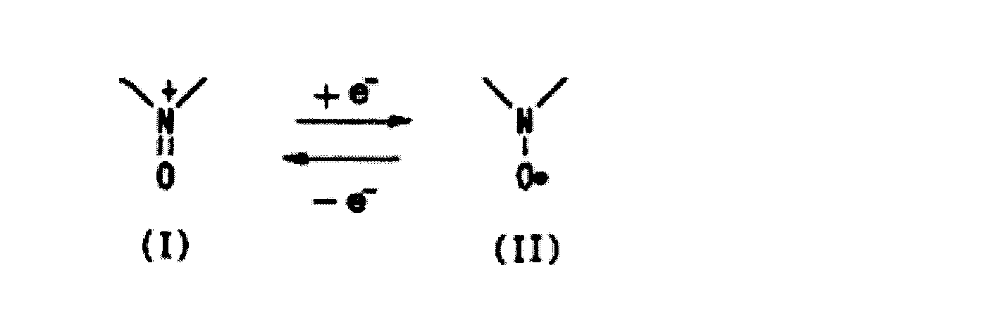
- An electricity storage device includes a nitroxyl compound having a nitroxyl cation partial structure represented by the following formula (I) in an oxidized state and a nitroxyl radical partial structure represented by the following formula (II) in a reduced state And a negative electrode containing a carbon material capable of reversibly inserting and removing lithium ions, and an electrolytic solution containing a lithium salt and an aprotic organic solvent, wherein the negative electrode is inserted during charge and discharge -It is a negative electrode containing the said carbon material into which lithium ion was inserted previously separately from the lithium ion concerned with the detachable lithium capacity A.
- an electricity storage device that simultaneously realizes high energy density, high output characteristics, low environmental load, and high stability in charge / discharge cycles.
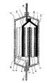
- FIG. 1 is a cross-sectional view of a laminated exterior power storage device that is an example of the power storage device according to the present embodiment.
- the basic configuration of the electricity storage device in the present embodiment shown in FIG. 1 includes a positive electrode 1 containing a nitroxyl compound, a positive electrode current collector 1A connected to the positive electrode 1, and energy connected to the positive electrode current collector 1A outside the cell. And a positive electrode lead 1B to be taken out.
- a negative electrode 2 containing a carbon material capable of reversibly inserting and removing lithium ions, a negative electrode current collector 2A connected to the negative electrode 2, and a negative electrode connected to the negative electrode current collector 2A to extract energy from the cell And leads 2B.
- a lithium supply source 3 for pre-doping the negative electrode 2 a lithium supply source current collector 3 ⁇ / b> A connected to the lithium supply source 3, between the positive electrode 1 and the negative electrode 2, and between the lithium supply source 3 and the positive electrode current collector 1 ⁇ / b> A
- the separator 4 is interposed between the separator 4 that does not conduct electrons but conducts only ions, and the exterior body 5 that seals them.
- the shape of the electricity storage device in this embodiment is not particularly limited.
- a cylindrical shape, a square shape, or the like can be appropriately selected depending on the application.
- the number of electrode layers may be a single layer or a plurality of layers. Further, when there are a plurality of layers, the stacking method or the winding method may be used.
- the positive electrode 1 in this embodiment contains a nitroxyl compound.
- a nitroxyl compound By using a nitroxyl compound, safety and reduction of environmental burden can be realized.
- the nitroxyl compound in the present embodiment is a compound that takes a nitroxyl cation partial structure represented by the formula (I) in an oxidized state and a nitroxyl radical partial structure represented by the formula (II) in a reduced state.
- the nitroxyl compound in an oxidized state, is 2,2,6,6-tetramethylpiperidinoxyl cation represented by the following formula (1), 2, Consists of 2,5,5-tetramethylpyrrolinoxyl cation, 2,2,5,5-tetramethylpyrrolinoxyl cation represented by the following formula (3), and nitronyl cation represented by the following formula (4)
- a polymer compound having one cyclic structure selected from the group is preferable.
- polymer compounds having this cyclic nitroxyl structure in the side chain, among them (meth) acrylate polymers and vinyl ether polymers are preferred.
- the main function of the nitroxyl compound in the positive electrode 1 is a role as an active material contributing to power storage. Therefore, as the proportion of the nitroxyl compound contained in the positive electrode 1 is increased, the energy density is improved.
- the proportion of the nitroxyl compound contained in the positive electrode 1 is not particularly limited, but it is preferable if it is contained in the positive electrode 1 in an amount of 1% by mass or more, and is more preferable if it is 10% by mass or more because a sufficient effect is seen. .
- the content is more preferably 30% by mass or more, and particularly preferably 50% by mass or more.
- the nitroxyl compound preferably has a crosslinked structure from the viewpoint of stability in the charge / discharge cycle.
- the degree of crosslinking of the nitroxyl compound having the crosslinked structure is preferably 0.5 to 6.0 mol%.
- the positive electrode 1 in this embodiment may further contain a conductive auxiliary agent, a binder, and the like.
- the conductive auxiliary agent include carbon materials such as carbon black, acetylene black, and carbon fiber, and conductive polymers such as polyacetylene, polyphenylene, polyaniline, and polypyrrole.
- the binder include resins such as polyvinylidene fluoride, polytetrafluoroethylene, vinylidene fluoride-hexafluoropropylene copolymer, styrene-butadiene copolymer rubber, polypropylene, polyethylene, and polyimide.
- Examples of the material of the positive electrode current collector 1A include aluminum, an aluminum alloy, and stainless steel.
- As the shape, a foil, a flat plate, or a mesh can be used.
- those having holes penetrating the front and back surfaces are preferable.
- a quality foil etc. can be mentioned.
- the shape, number, etc. of the through holes of the positive electrode current collector 1A are such that lithium ions in the electrolyte described later can move between the front and back of the electrode without being blocked by the positive electrode current collector 1A. Therefore, it can be set appropriately so as to be easily closed.
- Examples of the material of the positive electrode lead 1B include aluminum, an aluminum alloy, and stainless steel.
- As the shape, a foil, a flat plate, or a mesh can be used.
- the material of the negative electrode 2 in this embodiment includes a carbon material that can reversibly insert and desorb lithium ions. Specific examples include graphite, hard carbon, polyacene, activated carbon and the like.
- the negative electrode 2 in the present embodiment may include a conductivity imparting agent or a binder.
- the conductivity-imparting agent include carbon materials such as carbon black, acetylene black, and carbon fiber, and metal powder.
- the binder include polyvinylidene fluoride, polytetrafluoroethylene, vinylidene fluoride-hexafluoropropylene copolymer, styrene-butadiene copolymer rubber, polypropylene, polyethylene, and polyimide.
- anode 2 containing a carbon material capable of reversibly inserting and removing lithium ions by using an anode 2 containing a carbon material capable of reversibly inserting and removing lithium ions, and an electrolyte containing a lithium salt and an aprotic organic solvent described later,
- the operating voltage of the device can be increased, and both high energy density and power density can be achieved.
- the balance between the lithium capacity A in which the negative electrode 2 can be inserted / removed in charge / discharge and the lithium capacity C in which the positive electrode 1 can be inserted / removed in charge / discharge is not particularly limited.
- the lithium capacity indicates the capacity of lithium ions.
- the negative electrode The lithium capacity A 2 that can be inserted / removed in charge / discharge is preferably larger than the lithium capacity C that the positive electrode 1 can be inserted / removed in charge / discharge.
- C is preferably 1.1 or more, and more preferably 1.5 or more.
- the ratio A / C is preferably 10 or less, and more preferably 5 or less.
- the lithium capacity A in which the negative electrode 2 can be inserted / removed during charging / discharging is manufactured as a lithium metal counter electrode, charged at a 1 / 40C rate to 0V to lithium ratio, and similarly up to 1V at a 1 / 40C rate. The value measured by repeating the discharging cycle 10 times.
- the lithium capacity C that can be inserted / removed in the charge / discharge of the positive electrode 1 is a lithium metal counter electrode, charged at a rate of 1/10 C to a lithium ratio of 4 V, and also at a rate of 1/10 C up to 3 V The value measured by repeating the discharging cycle 10 times.
- Examples of the material of the negative electrode current collector 2A include copper, nickel, and stainless steel.
- a foil, a flat plate, or a mesh can be used.
- those having holes penetrating the front and back surfaces are preferable.
- a quality foil etc. can be mentioned.
- the shape and number of through-holes of the negative electrode current collector 2A are such that lithium ions in the electrolyte described later can move between the front and back of the electrode without being blocked by the negative electrode current collector 2A. Therefore, it can be set appropriately so as to be easily closed.
- Examples of the material of the negative electrode lead 2B include copper, nickel, and stainless steel.
- a foil, a flat plate, or a mesh can be used.
- the electricity storage device in the present embodiment is in a state where lithium ions are inserted and supported on the negative electrode 2 when the nitroxyl compound contained in the positive electrode 1 is in a discharge state in which the nitroxyl radical partial structure represented by the formula (II) is taken. It is characterized by that. That is, even when the positive electrode 1 is in a completely discharged state, that is, in a state where no energy is stored, the negative electrode 2 is still loaded with lithium ions and is in a partially charged state. It is a feature.
- the negative electrode 2 is the carbon material in which lithium ions are inserted in advance separately from lithium ions involved in the lithium capacity A that can be inserted / removed in charge / discharge. It is characterized by including.
- a positive electrode including a nitroxyl compound having a nitroxyl radical partial structure represented by the formula (II) is used as the positive electrode 1, and lithium ions are inserted into the negative electrode 2 in advance. It is produced using a negative electrode containing the carbon material.
- lithium ions are inserted in advance into the carbon material constituting the negative electrode 2 and used as the negative electrode 2 separately from lithium ions derived from the lithium salt in the electrolyte solution involved in charging and discharging.
- the electrical storage device which concerns on this embodiment can acquire the outstanding stability in a charging / discharging cycle.
- the lithium capacity carried by the negative electrode that is, the lithium capacity previously inserted in the negative electrode 2 is as follows. There is no particular limitation. However, in order to show a sufficient stability improvement effect, it is preferable that 10% or more of lithium capacity A in which the negative electrode 2 can be inserted / removed in charge / discharge and lithium ions are inserted in advance, and 40% or more in advance. More preferably, it is inserted.
- the negative electrode 2 can be inserted / removed in charge / discharge at 200% or less of the lithium capacity A. It is preferable that it is 120% or less.
- the lithium capacity inserted in advance in the negative electrode 2 is that the lithium metal serving as the lithium supply source 3 is inserted into the carbon material in advance when the storage device is a laminate type battery. By measuring the weight of the lithium supply source 3 to be charged, the lithium capacity inserted in advance can be calculated. Further, in the case of a coin-type battery, which will be described later, since lithium ions are inserted while being controlled electrochemically, the lithium capacity inserted in advance can be calculated from the integrated value of the current passed through the cell.
- the method of inserting lithium ions in advance separately from the lithium ions involved in the lithium capacity A that can be inserted into and removed from the negative electrode 2 during charging and discharging there is no particular limitation on the method of inserting lithium ions in advance separately from the lithium ions involved in the lithium capacity A that can be inserted into and removed from the negative electrode 2 during charging and discharging.
- a lithium ion supply source is provided in the power storage device in advance and the lithium ion is inserted by electrochemical contact with the negative electrode 2 or a lithium ion is previously inserted by an electrochemical method.
- Examples include a method for manufacturing an electricity storage device.
- a lithium supply source 3 for inserting lithium ions in advance separately from the lithium ions related to the lithium capacity A that can be inserted / removed in the negative electrode 2 during charging / discharging is provided. .
- the lithium metal of the lithium supply source 3 is inserted and supported on the carbon material of the negative electrode 2 as lithium ions.
- the nitroxyl compound contained in the positive electrode 1 is designed to be in a state in which lithium ions are inserted and supported in the negative electrode 2 when the nitroxyl compound in the discharge state has the nitroxyl radical partial structure represented by the formula (II).
- Examples of the material used as the lithium supply source 3 include lithium metal and lithium aluminum alloy, and lithium metal is particularly preferable.
- Examples of the material of the lithium supply source current collector 3A include copper, nickel, and stainless steel. As the shape, a foil, a flat plate, or a mesh can be used.
- the electricity storage device in the present embodiment is not limited with respect to the amount of lithium ions that the lithium supply source 3 can supply to the negative electrode 2.
- lithium ions are supplied to 10% or more of the lithium capacity A in which the negative electrode 2 can be inserted / removed in charge / discharge, and are inserted / supported. It is preferable that it is 40% or more.
- the negative electrode 2 can be inserted / extracted during charging / discharging at 200% or less of the lithium capacity A.
- Lithium ions are preferably supplied, inserted and supported, and more preferably 120% or less.
- the separator 4 in FIG. 1 is interposed between the positive electrode 1 and the negative electrode 2 and between the lithium supply source 3 and the positive electrode current collector 1A, and plays a role of conducting only ions without conducting electrons.
- the separator 4 is not particularly limited, and a conventionally known separator can be used. Examples thereof include polyolefins such as polypropylene and polyethylene, and porous films such as fluororesin.
- the separator 4 holds an aprotic organic solvent electrolyte containing a lithium salt and is responsible for ion conduction.
- the aprotic organic solvent electrolyte containing a lithium salt preferably has an ionic conductivity of 10 ⁇ 5 to 10 ⁇ 1 S / cm at room temperature.
- lithium salt in the present embodiment examples include LiPF 6 , LiClO 4 , LiBF 4 , LiSbF 6 , LiN (CF 3 SO 2 ) 2 , LiN (C 2 F 5 SO 2 ) 2 , LiB (C 2 O 4 ) 2. Etc.
- the lithium salt is preferably LiBF 4 or LiPF 6 . These may be used alone or in combination of two or more.
- examples of the aprotic organic solvent in this embodiment include cyclic carbonates such as propylene carbonate (PC), ethylene carbonate (EC), butylene carbonate (BC), and vinylene carbonate (VC), dimethyl carbonate (DMC), and diethyl carbonate.
- cyclic carbonates such as propylene carbonate (PC), ethylene carbonate (EC), butylene carbonate (BC), and vinylene carbonate (VC), dimethyl carbonate (DMC), and diethyl carbonate.
- DEC chain carbonates such as ethyl methyl carbonate (EMC), dipropyl carbonate (DPC), aliphatic carboxylic acid esters such as methyl formate, methyl acetate, ethyl propionate, ⁇ -butyrolactone (GBL), etc.
- Lactones chain ethers such as dimethoxyethane (DME), diethoxyethane (DEE) and ethoxymethoxyethane (EME), cyclic ethers such as tetrahydrofuran and methyltetrahydrofuran, 1-ethyl-3-methyl Midazoriumu TFSI, such ionic liquids such as N- butyl -N- methyl-pyrrolidinium TFSI and the like.
- DEC, EC, PC, BC, DME, and GBL are preferable as the aprotic organic solvent.
- These aprotic organic solvents may be used individually by 1 type, or may mix 2 or more types.
- the concentration of the lithium salt relative to the aprotic organic solvent is not particularly limited, but is preferably in the range of 0.4 to 1.5 mol / L from the viewpoint of exhibiting sufficient ionic conductivity.
- the material of the exterior body 5 is not particularly limited, and a conventionally known material can be used.
- a metal material such as iron or aluminum, a plastic material, a glass material, or a composite material obtained by laminating them can be used.
- a laminate film outer package in which aluminum and a polymer film such as nylon or polypropylene are laminated is preferable.
- FIG. 2 is an exploded perspective view of a coin exterior type power storage device which is another example of the power storage device according to the present embodiment.
- the basic configuration of the electricity storage device is connected to the positive electrode 6 containing the nitroxyl compound, the separator 8 made of porous polypropylene or cellulose, the negative electrode 7 containing the carbon material into which lithium ions have been inserted, and the positive electrode 6.
- the method of inserting lithium ions into the negative electrode 7 in advance and carrying it is not particularly limited.
- the negative electrode 7 containing a carbon material is immersed in an electrolytic solution, and lithium ions are electrochemically inserted into the negative electrode 7 using a lithium foil as a counter electrode. Can be carried.
- a lithium foil as a counter electrode.
- other structures, such as material it is the same as that of the laminated exterior type electrical storage device mentioned above.
- the polymer was precipitated in hexane, separated by filtration, and dried under reduced pressure to obtain 18 g (yield 90%) of poly (2,2,6,6-tetramethylpiperidine methacrylate).
- 10 g of the obtained poly (2,2,6,6-tetramethylpiperidine methacrylate) was dissolved in 100 ml of dry-treated dichloromethane.
- 100 ml of a dichloromethane solution of 15.2 g (0.088 mol) of m-chloroperbenzoic acid was added dropwise over 1 hour with stirring at room temperature.
- the structure of the obtained polymer was confirmed by IR.
- the obtained crosslinked product was insoluble in organic solvents such as methanol, ethanol, acetone, ethyl acetate, tetrahydrofuran, dimethylformamide, and dimethyl sulfoxide.
- the structure of the obtained polymer was confirmed by IR.
- the obtained crosslinked product was unnecessary for methanol, ethanol, acetone, ethyl acetate, tetrahydrofuran, dimethylformamide, and dimethyl sulfoxide.
- Table 1 shows the PTMA and crosslinked PTMA synthesized in Synthesis Examples 1-41.
- the solubility with respect to an organic solvent shows the solubility with respect to methanol, ethanol, acetone, ethyl acetate, tetrahydrofuran, dimethylformamide, and dimethylsulfoxide, and if it melt
- the structure of the obtained polymer was confirmed by IR.
- the obtained crosslinked product was insoluble in methanol, ethanol, acetone, ethyl acetate, tetrahydrofuran, dimethylformamide, and dimethyl sulfoxide (organic solvent).
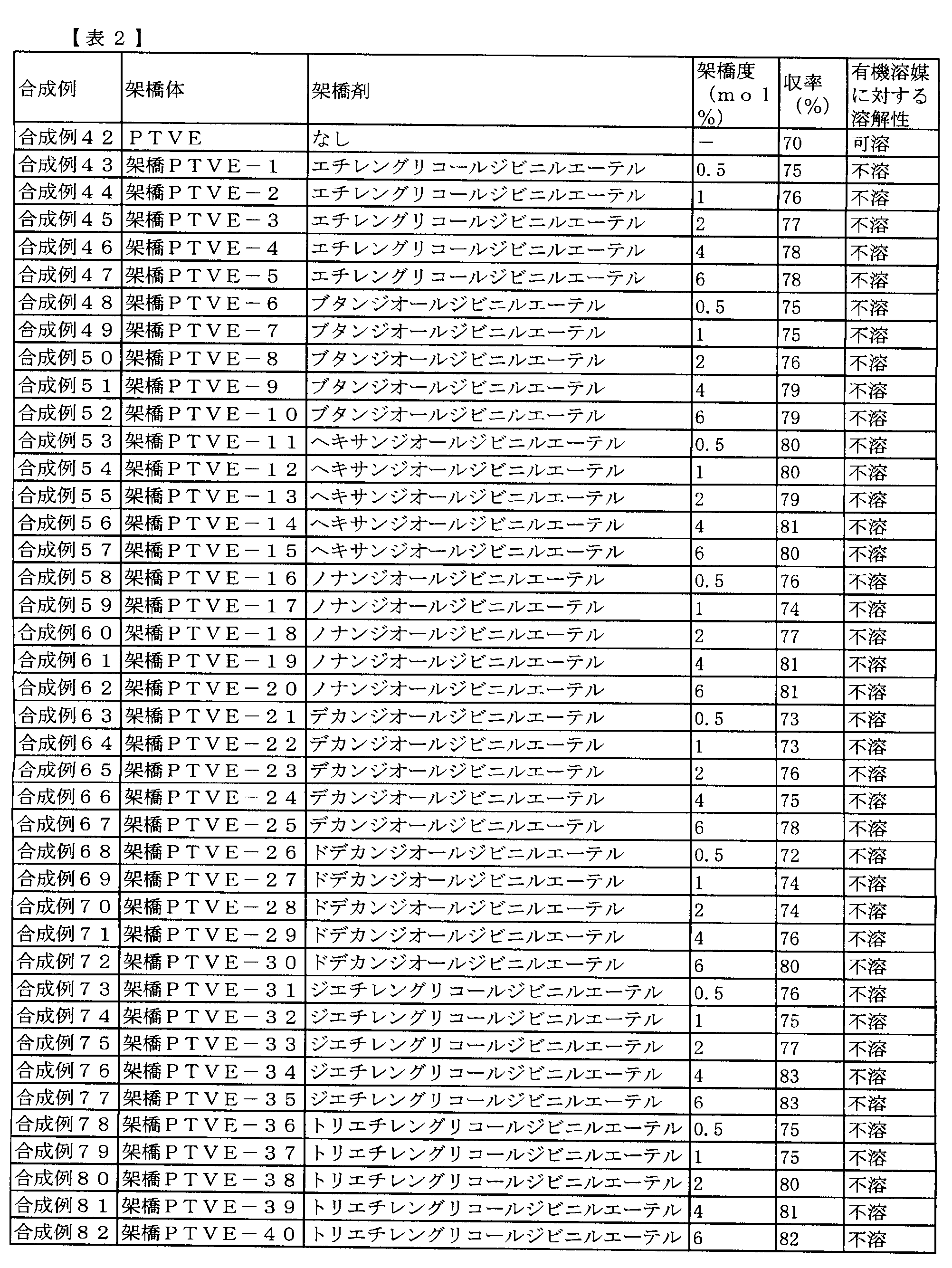
- Table 2 below shows the PTVE and crosslinked PTVE synthesized in Synthesis Examples 42 to 82.
- ⁇ Preparation of positive electrode (polymer content 60 mass%)> 3.6 g of the nitroxyl compound finely divided in advance, 2.1 g of vapor-grown carbon fiber, 240 mg of carboxymethyl cellulose, 60 mg of polytetrafluoroethylene fine powder, and 24 g of water were mixed well to prepare a positive electrode slurry.
- the positive electrode slurry was applied to an expanded metal aluminum current collector with a thickness of 38 ⁇ m, and water was sufficiently vaporized, and then stored overnight at 80 ° C. by vacuum drying to produce a positive electrode containing 60% by mass of a nitroxyl compound. .
- the total thickness of the positive electrode including the current collector was 100 to 400 ⁇ m.
- a positive electrode slurry was prepared by thoroughly mixing 4.2 g of the nitroxyl compound, 1.5 g of vapor-grown carbon fiber, 240 mg of carboxymethyl cellulose, 60 mg of polytetrafluoroethylene fine powder, and 24 g of water.
- the positive electrode slurry was applied to an expanded metal aluminum current collector with a thickness of 38 ⁇ m, and water was sufficiently vaporized, and then stored at 80 ° C. overnight by vacuum drying to produce a positive electrode containing 70% by mass of a nitroxyl compound. .
- the total thickness of the positive electrode including the current collector was 100 to 400 ⁇ m.
- ⁇ Preparation of positive electrode (polymer content 80 mass%)> 4.8 g of the nitroxyl compound finely divided in advance, 0.9 g of vapor-grown carbon fiber, 240 mg of carboxymethyl cellulose, 60 mg of polytetrafluoroethylene fine powder, and 24 g of water were mixed well to prepare a positive electrode slurry.
- the positive electrode slurry was applied to an expanded metal aluminum current collector with a thickness of 38 ⁇ m, and after sufficiently evaporating water, it was stored overnight at 80 ° C. by vacuum drying to produce a positive electrode containing 80% by mass of a nitroxyl compound. .
- the total thickness of the positive electrode including the current collector was 100 to 400 ⁇ m.
- a slurry of the negative electrode was applied to both sides of an expanded metal copper foil having a thickness of 32 ⁇ m coated with a carbon-based conductive paint, and vacuum-dried to prepare a negative electrode containing 90% by mass of graphite.
- Example 1 A positive electrode containing 70% by mass of a nitroxyl compound (PTMA), a negative electrode containing 90% by mass of the graphite, a mixed electrolyte of ethylene carbonate and diethyl carbonate containing a LiPF 6 supporting salt at a concentration of 1 mol / L, a lithium source for pre-doping, Using the resulting lithium foil, a laminate exterior type electricity storage device shown in FIG. 1 was produced.
- PTMA nitroxyl compound
- a negative electrode containing 90% by mass of the graphite a mixed electrolyte of ethylene carbonate and diethyl carbonate containing a LiPF 6 supporting salt at a concentration of 1 mol / L
- LiPF 6 supporting salt a LiPF 6 supporting salt at a concentration of 1 mol / L
- the positive electrode 1 and the negative electrode 2 were sequentially stacked with the separator 4 interposed therebetween to produce an electrode laminate.
- a lithium metal-laminated copper foil serving as the lithium supply source 3 was inserted into the uppermost part of the electrode laminate.
- the aluminum foil as the positive electrode current collector 1A and the positive electrode lead 1B are ultrasonically welded, and the copper foil as the negative electrode current collector 2A, the copper foil as the lithium source current collector 3A, and the negative electrode lead 2B are also welded. did. They were covered with an outer package 5 made of an aluminum laminate film having a thickness of 115 ⁇ m, and the three sides including the lead portions were heat-sealed first.
- the lithium capacity inserted into the negative electrode that is, the lithium capacity previously inserted into the negative electrode
- the film thickness of the electrode is adjusted to 60% of the lithium capacity A that can be inserted / removed in charge / discharge. Further, the film thickness of the electrode is set such that the ratio A / C of the lithium capacity A that can be inserted / removed in charge / discharge of the negative electrode and the lithium capacity C that can be inserted / removed in charge / discharge of the positive electrode becomes 3.0.
- the open electromotive force of the fabricated cell was 3.2V.
- FIG. 2 shows a lithium ion-inserted negative electrode thus obtained, a positive electrode containing 70% by mass of a nitroxyl compound (PTMA), and a mixed electrolyte solution of ethylene carbonate and diethyl carbonate containing a LiPF 6 supporting salt having a concentration of 1 mol / L.
- PTMA nitroxyl compound
- the lithium capacity inserted into the negative electrode that is, the lithium capacity previously inserted into the negative electrode is inserted when the negative electrode is charged / discharged.
- the film thickness of the electrode is adjusted to be 60% of the detachable lithium capacity A. Further, the film thickness of the electrode is set such that the ratio A / C of the lithium capacity A that can be inserted / removed in charge / discharge of the negative electrode and the lithium capacity C that can be inserted / removed in charge / discharge of the positive electrode becomes 3.0 Has been adjusted.
- the open electromotive force of the fabricated cell was 3.2V.
- Example 3 When the nitroxyl compound (PTMA) contained in the positive electrode is in a discharge state having a nitroxyl radical partial structure, the lithium capacity inserted into the negative electrode, that is, the lithium capacity previously inserted into the negative electrode is inserted into the negative electrode during charge / discharge.
- the film thickness of the electrode is adjusted so as to be 5% of the detachable lithium capacity A.
- the film thickness of the electrode is adjusted so that the ratio A / C between the lithium capacity A that can be inserted / removed during charging / discharging and the lithium capacity C that can be inserted / removed during charging / discharging becomes 3.0. It is. Otherwise, a coin-type electricity storage device was produced in the same manner as in Example 2.
- the open electromotive force of the produced cell was 2.7V.
- this cell was repeatedly charged and discharged at a current density of 0.5 mA / cm 2 and a voltage of 3.0 to 4.0 V, a residual capacity of 63% of the initial capacity was obtained after 500 cycles. Furthermore, the capacity retention rate after 500 cycles at 50 ° C. was a residual capacity of 55% of the initial capacity.
- Example 4 When the nitroxyl compound (PTMA) contained in the positive electrode is in a discharge state having a nitroxyl radical partial structure, the lithium capacity inserted into the negative electrode, that is, the lithium capacity previously inserted into the negative electrode is inserted into the negative electrode during charge / discharge.
- the film thickness of the electrode is adjusted to be 10% of the detachable lithium capacity A.
- the film thickness of the electrode is adjusted so that the ratio A / C between the lithium capacity A that can be inserted / removed during charging / discharging and the lithium capacity C that can be inserted / removed during charging / discharging becomes 3.0. It is. Otherwise, a coin-type electricity storage device was produced in the same manner as in Example 2.
- the open electromotive force of the produced cell was 3.0V.
- this cell was repeatedly charged and discharged at a current density of 0.5 mA / cm 2 and a voltage in the range of 3.0 to 4.0 V, a residual capacity of 83% of the initial capacity was obtained after 500 cycles. Furthermore, the capacity retention rate after 500 cycles at 50 ° C. was a residual capacity of 76% of the initial capacity.
- Example 5 When the nitroxyl compound (PTMA) contained in the positive electrode is in a discharge state having a nitroxyl radical partial structure, the lithium capacity inserted into the negative electrode, that is, the lithium capacity previously inserted into the negative electrode is inserted into the negative electrode during charge / discharge.
- the film thickness of the electrode is adjusted to 40% of the detachable lithium capacity A.
- the film thickness of the electrode is adjusted so that the ratio A / C between the lithium capacity A that can be inserted / removed during charging / discharging and the lithium capacity C that can be inserted / removed during charging / discharging becomes 3.0. It is. Otherwise, a coin-type electricity storage device was produced in the same manner as in Example 2.
- the open electromotive force of the fabricated cell was 3.1V.
- this cell was repeatedly charged and discharged at a current density of 0.5 mA / cm 2 and a voltage of 3.0 to 4.0 V, a residual capacity of 92% of the initial capacity was obtained after 500 cycles. Furthermore, the capacity retention rate after 500 cycles at 50 ° C. was a residual capacity of 84% of the initial capacity.
- Example 6 When the nitroxyl compound (PTMA) contained in the positive electrode is in a discharge state having a nitroxyl radical partial structure, the lithium capacity inserted into the negative electrode, that is, the lithium capacity previously inserted into the negative electrode is inserted into the negative electrode during charge / discharge.
- the film thickness of the electrode is adjusted to be 120% of the detachable lithium capacity A.
- the film thickness of the electrode is adjusted so that the ratio A / C between the lithium capacity A that can be inserted / removed during charging / discharging and the lithium capacity C that can be inserted / removed during charging / discharging becomes 3.0. It is. Otherwise, a coin-type electricity storage device was produced in the same manner as in Example 2.
- the open electromotive force of the fabricated cell was 3.3V.
- this cell was repeatedly charged and discharged at a current density of 0.5 mA / cm 2 and a voltage of 3.0 to 4.0 V, a residual capacity of 92% of the initial capacity was obtained after 500 cycles. Furthermore, the capacity retention rate after 500 cycles at 50 ° C. was a residual capacity of 80% of the initial capacity.
- Example 7 When the nitroxyl compound (PTMA) contained in the positive electrode is in a discharge state having a nitroxyl radical partial structure, the lithium capacity inserted into the negative electrode, that is, the lithium capacity previously inserted into the negative electrode is inserted into the negative electrode during charge / discharge.
- the film thickness of the electrode is adjusted to be 200% of the detachable lithium capacity A.
- the film thickness of the electrode is adjusted so that the ratio A / C between the lithium capacity A that can be inserted / removed during charging / discharging and the lithium capacity C that can be inserted / removed during charging / discharging becomes 3.0. It is. Otherwise, a coin-type electricity storage device was produced in the same manner as in Example 2.
- the open electromotive force of the fabricated cell was 3.3V.
- this cell was repeatedly charged and discharged at a current density of 0.5 mA / cm 2 and a voltage of 3.0 to 4.0 V, a residual capacity of 85% of the initial capacity was obtained after 500 cycles. Furthermore, the capacity retention rate after 500 cycles at 50 ° C. was a residual capacity of 76% of the initial capacity.
- Example 8 When the nitroxyl compound (PTMA) contained in the positive electrode is in a discharge state having a nitroxyl radical partial structure, the lithium capacity inserted into the negative electrode, that is, the lithium capacity previously inserted into the negative electrode is inserted into the negative electrode during charge / discharge.
- the film thickness of the electrode is adjusted to be 250% of the detachable lithium capacity A.
- the film thickness of the electrode is adjusted so that the ratio A / C between the lithium capacity A that can be inserted / removed during charging / discharging and the lithium capacity C that can be inserted / removed during charging / discharging becomes 3.0. It is. Otherwise, a coin-type electricity storage device was produced in the same manner as in Example 2.
- the open electromotive force of the fabricated cell was 3.4V.
- this cell was repeatedly charged and discharged at a current density of 0.5 mA / cm 2 and a voltage of 3.0 to 4.0 V, a residual capacity of 71% of the initial capacity was obtained after 500 cycles. Furthermore, the capacity retention rate after 500 cycles at 50 ° C. was a residual capacity of 62% of the initial capacity.
- Example 9 When the nitroxyl compound (PTMA) contained in the positive electrode is in a discharge state having a nitroxyl radical partial structure, the lithium capacity inserted into the negative electrode, that is, the lithium capacity previously inserted into the negative electrode is inserted into the negative electrode during charge / discharge.
- the film thickness of the electrode is adjusted to 40% of the detachable lithium capacity A.
- the film thickness of the electrode is adjusted so that the ratio A / C between the lithium capacity A that can be inserted / removed during charging / discharging and the lithium capacity C that can be inserted / removed during charging / discharging becomes 1.0. It is. Otherwise, a coin-type electricity storage device was produced in the same manner as in Example 2.
- the open electromotive force of the fabricated cell was 3.2V.
- this cell was repeatedly charged and discharged at a current density of 0.5 mA / cm 2 and a voltage of 3.0 to 4.0 V, a residual capacity of 23% of the initial capacity was obtained after 500 cycles. Further, the capacity retention rate after 500 cycles at 50 ° C. was a residual capacity of 11% of the initial capacity.
- Example 10 When the nitroxyl compound (PTMA) contained in the positive electrode is in a discharge state having a nitroxyl radical partial structure, the lithium capacity inserted into the negative electrode, that is, the lithium capacity previously inserted into the negative electrode is inserted into the negative electrode during charge / discharge.
- the film thickness of the electrode is adjusted to 40% of the detachable lithium capacity A.
- the film thickness of the electrode is adjusted so that the ratio A / C between the lithium capacity A that can be inserted / removed during charge / discharge and the lithium capacity C that can be inserted / removed during charge / discharge is 1.1. It is. Otherwise, a coin-type electricity storage device was produced in the same manner as in Example 2.
- the open electromotive force of the fabricated cell was 3.2V.
- this cell was repeatedly charged and discharged at a current density of 0.5 mA / cm 2 and a voltage in the range of 3.0 to 4.0 V, a residual capacity of 72% of the initial capacity was obtained after 500 cycles. Furthermore, the capacity retention rate after 500 cycles at 50 ° C. was a residual capacity of 60% of the initial capacity.
- Example 11 When the nitroxyl compound (PTMA) contained in the positive electrode is in a discharge state having a nitroxyl radical partial structure, the lithium capacity inserted into the negative electrode, that is, the lithium capacity previously inserted into the negative electrode is inserted into the negative electrode during charge / discharge.
- the film thickness of the electrode is adjusted to 40% of the detachable lithium capacity A.
- the film thickness of the electrode is adjusted so that the ratio A / C between the lithium capacity A that can be inserted / removed during charge / discharge and the lithium capacity C that can be inserted / removed during charge / discharge is 1.5. It is. Otherwise, a coin-type electricity storage device was produced in the same manner as in Example 2.
- the open electromotive force of the fabricated cell was 3.2V.
- Example 12 When the nitroxyl compound (PTMA) contained in the positive electrode is in a discharge state having a nitroxyl radical partial structure, the lithium capacity inserted into the negative electrode, that is, the lithium capacity previously inserted into the negative electrode is inserted into the negative electrode during charge / discharge.
- the film thickness of the electrode is adjusted to be 60% of the detachable lithium capacity A.
- the film thickness of the electrode is adjusted so that the ratio A / C between the lithium capacity A that can be inserted / removed during charge / discharge and the lithium capacity C that can be inserted / removed during charge / discharge is 5.0. It is. Otherwise, a coin-type electricity storage device was produced in the same manner as in Example 2.
- the open electromotive force of the fabricated cell was 3.2V.
- this cell was repeatedly charged and discharged at a current density of 0.5 mA / cm 2 and a voltage in the range of 3.0 to 4.0 V, a residual capacity of 90% of the initial capacity was obtained after 500 cycles. Furthermore, the capacity retention rate after 500 cycles at 50 ° C. was a residual capacity of 79% of the initial capacity.
- Example 13 When the nitroxyl compound (PTMA) contained in the positive electrode is in a discharge state having a nitroxyl radical partial structure, the lithium capacity inserted into the negative electrode, that is, the lithium capacity previously inserted into the negative electrode is inserted into the negative electrode during charge / discharge.
- the film thickness of the electrode is adjusted to be 60% of the detachable lithium capacity A.
- the film thickness of the electrode is adjusted so that the ratio A / C between the lithium capacity A that can be inserted / removed during charge / discharge and the lithium capacity C that can be inserted / removed during charge / discharge is 10.0. It is. Otherwise, a coin-type electricity storage device was produced in the same manner as in Example 2.
- the open electromotive force of the fabricated cell was 3.1V.
- this cell was repeatedly charged and discharged at a current density of 0.5 mA / cm 2 and a voltage of 3.0 to 4.0 V, a residual capacity of 85% of the initial capacity was obtained after 500 cycles. Furthermore, the capacity retention rate after 500 cycles at 50 ° C. was a residual capacity of 71% of the initial capacity.
- Example 14 When the nitroxyl compound (PTMA) contained in the positive electrode is in a discharge state having a nitroxyl radical partial structure, the lithium capacity inserted into the negative electrode, that is, the lithium capacity previously inserted into the negative electrode is inserted into the negative electrode during charge / discharge.
- the film thickness of the electrode is adjusted to be 60% of the detachable lithium capacity A.
- the film thickness of the electrode is adjusted so that the ratio A / C between the lithium capacity A that can be inserted / removed during charge / discharge and the lithium capacity C that can be inserted / removed during charge / discharge is 15.0. It is. Otherwise, a coin-type electricity storage device was produced in the same manner as in Example 2.
- the open electromotive force of the fabricated cell was 3.2V.
- this cell was repeatedly charged and discharged at a current density of 0.5 mA / cm 2 and a voltage of 3.0 to 4.0 V, a residual capacity of 77% of the initial capacity was obtained after 500 cycles. Furthermore, the capacity retention rate after 500 cycles at 50 ° C. was a residual capacity of 66% of the initial capacity.
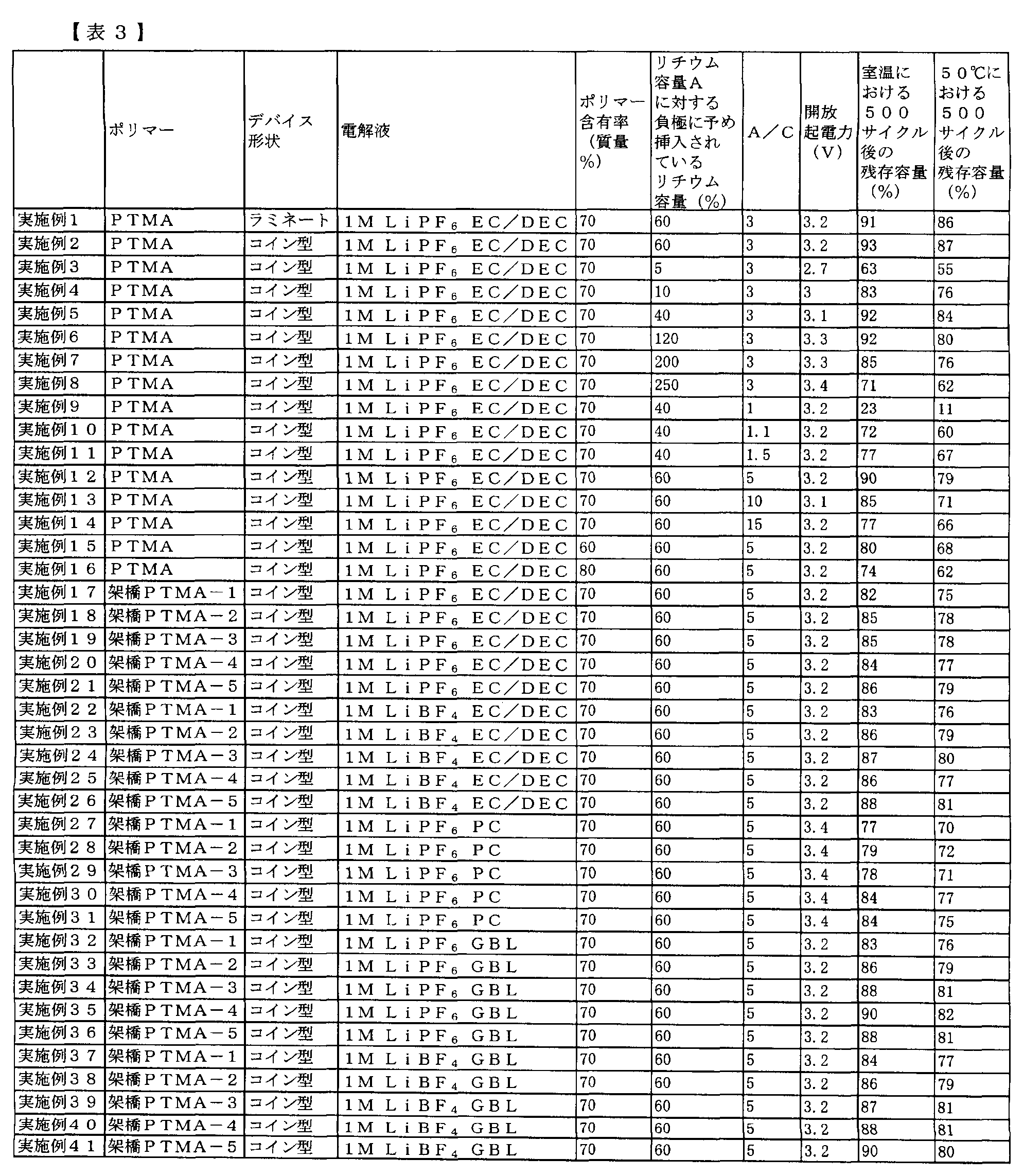
- Examples 15 to 76> The cross-linked polymer (cross-linked PTMA, cross-linked PTVE) shown in the above synthesis example is used as the nitroxyl compound, and further, any of ethylene carbonate / diethyl carbonate mixed solvent, propylene carbonate, and ⁇ -butyrolactone is used as the electrolyte solvent, and the supporting salt is used. Batteries (coin type and laminate type) were produced and evaluated in the same manner as in Examples 1 to 14 except that either LiPF 6 or LiBF 4 was used.
- a laminated exterior type electricity storage device was produced in the same manner as in Example 1 without using a lithium foil as a supply source. Since lithium ions are not inserted into the negative electrode in advance, the electricity storage device has no lithium ions inserted into the negative electrode when the nitroxyl compound (PTMA) contained in the positive electrode has a nitroxyl radical partial structure.
- the electrode film thickness is adjusted so that the ratio A / C between the lithium capacity A that can be inserted / removed during charge / discharge of the negative electrode and the lithium capacity C that can be inserted / removed during charge / discharge of the positive electrode is 1.0. It is.
- the open electromotive force of the fabricated cell was -0.1V. When this cell was repeatedly charged and discharged at a current density of 0.5 mA / cm 2 and a voltage of 3.0 to 4.0 V, a residual capacity of 34% of the initial capacity was obtained after 500 cycles. Furthermore, the capacity retention rate after 500 cycles at 50 ° C. was a residual capacity of 10% of the initial capacity.
- a coin-type electricity storage device was prepared in the same manner as in Example 2 using the mixed electrolyte solution. Since lithium ions are not inserted into the negative electrode in advance, the electricity storage device has no lithium ions inserted into the negative electrode when the nitroxyl compound (PTMA) contained in the positive electrode has a nitroxyl radical partial structure.
- the electrode film thickness is adjusted so that the ratio A / C between the lithium capacity A that can be inserted / removed during charge / discharge of the negative electrode and the lithium capacity C that can be inserted / removed during charge / discharge of the positive electrode is 1.0. It is.
- the open electromotive force of the fabricated cell was -0.2V. When this cell was repeatedly charged and discharged at a current density of 0.5 mA / cm 2 and a voltage in the range of 3.0 to 4.0 V, a residual capacity of 24% of the initial capacity was obtained after 500 cycles. Furthermore, the capacity retention rate after 500 cycles at 50 ° C. was a residual capacity of 8% of the initial capacity.
- a coin-type electricity storage device was prepared in the same manner as in Example 2 using the mixed electrolyte solution. Since lithium ions are not inserted into the negative electrode in advance, the electricity storage device has no lithium ions inserted into the negative electrode when the nitroxyl compound (PTMA) contained in the positive electrode has a nitroxyl radical partial structure.
- the electrode thickness was adjusted so that the ratio A / C between the lithium capacity A that can be inserted / removed during charge / discharge of the negative electrode and the lithium capacity C that can be inserted / removed during charge / discharge of the positive electrode was 3.0. It is.
- the open electromotive force of the fabricated cell was -0.1V. When this cell was repeatedly charged and discharged at a current density of 0.5 mA / cm 2 and a voltage of 3.0 to 4.0 V, a residual capacity of 22% of the initial capacity was obtained after 500 cycles. Furthermore, the capacity retention rate after 500 cycles at 50 ° C. was a residual capacity of 6% of the initial capacity.
- a positive electrode containing 70% by mass of a nitroxyl compound (PTVE), a negative electrode not containing lithium ions containing 90% by mass of graphite, and a mixed electrolyte of ethylene carbonate and diethyl carbonate containing a LiPF6 supporting salt with a concentration of 1 mol / L A coin-type electricity storage device was manufactured. Since lithium ions are not inserted into the negative electrode in advance, lithium ions are not inserted into the negative electrode when the nitroxyl compound (PTVE) contained in the positive electrode is in a discharge state having a nitroxyl radical partial structure.
- the electrode film thickness is adjusted so that the ratio A / C between the lithium capacity A that can be inserted / removed during charge / discharge of the negative electrode and the lithium capacity C that can be inserted / removed during charge / discharge of the positive electrode is 1.0. It is.
- the open electromotive force of the fabricated cell was -0.1V. When this cell was repeatedly charged and discharged at a current density of 0.5 mA / cm 2 and a voltage of 3.0 to 4.0 V, a residual capacity of 13% of the initial capacity was obtained after 500 cycles. Furthermore, the capacity retention rate after 500 cycles at 50 ° C. was a residual capacity of 4% of the initial capacity.
- the nitroxyl compound contained in the positive electrode was converted into a nitroxyl radical. It has been clarified that the open electromotive force is greatly increased and the stability against the charge / discharge cycle is improved by the lithium ion inserted into the negative electrode in the discharge state having the partial structure.
- the ratio of the lithium capacity inserted in advance into the negative electrode to the lithium capacity A is preferably in the range of 10% or more and 200% or less, and 40% or more and 120% or less. It turned out that it is more preferable.
- the ratio A / C between the lithium capacity A and the lithium capacity C is preferably in the range of 1.1 or more and 10.0 or less, 1.5 or more, It turned out that it is more preferable to exist in the range of 5.0 or less. From the results of Examples 17 to 76, it was revealed that the stability was improved even when a crosslinked polymer was used as the nitroxyl compound. Further, it was shown that the electrolyte solution was excellent in stability even when any of ethylene carbonate / diethyl carbonate mixed solvent, propylene carbonate, and ⁇ -butyrolactone was used. Furthermore, it has been clarified that either LiBF 4 or LiPF 6 is used as the supporting salt, which is excellent in stability. A comparison between Example 1 and Examples 52 to 56 and other examples shows that the device has high stability even when a laminated cell is used as well as a coin-type cell.
- the electricity storage device in the present invention can simultaneously achieve high energy density, high output characteristics, low environmental load, and high safety. For this reason, power storage devices for driving or auxiliary use such as electric vehicles and hybrid electric vehicles, power sources for various portable electronic devices that require high output, power storage devices for various types of energy such as solar energy and wind power generation, or household appliances It can be used as a storage power source or the like.
Landscapes
- Engineering & Computer Science (AREA)
- Chemical & Material Sciences (AREA)
- Power Engineering (AREA)
- Chemical Kinetics & Catalysis (AREA)
- Electrochemistry (AREA)
- Microelectronics & Electronic Packaging (AREA)
- Materials Engineering (AREA)
- General Chemical & Material Sciences (AREA)
- Manufacturing & Machinery (AREA)
- Physics & Mathematics (AREA)
- Condensed Matter Physics & Semiconductors (AREA)
- General Physics & Mathematics (AREA)
- Inorganic Chemistry (AREA)
- Battery Electrode And Active Subsutance (AREA)
- Secondary Cells (AREA)
- Cell Electrode Carriers And Collectors (AREA)
Abstract
Description


-(CH2-CH2-O)n- (5)
(前記式(5)において、n=1~3とする)。
還流管を付けた100mlナスフラスコ中に、2,2,6,6-テトラメチルピペリジンメタクリレートモノマー20g(0.089mol)を入れ、乾燥テトラヒドロフラン80mlに溶解させた。そこへ、アゾビスイソブチロニトリル(AIBN)0.29g(0.00187mol)(モノマー/AIBN質量比=50/1)を加え、アルゴン雰囲気下75~80℃で攪拌した。6時間反応後、室温まで放冷した。へキサン中でポリマーを析出させて濾別し、減圧乾燥してポリ(2,2,6,6-テトラメチルピペリジンメタクリレート)18g(収率90%)を得た。次に、得られたポリ(2,2,6,6-テトラメチルピペリジンメタクリレート)10gを乾操ジクロロメタン100mlに溶解させた。ここへm-クロロ過安息香酸15.2g(0.088mol)のジクロロメタン溶液100mlを室温にて攪拌しながら1時間かけて滴下した。さらに6時間攪拌後、沈殿したm-クロロ安息香酸を濾別して除き、濾液を炭酸ナトリウム水溶液及び水で洗浄後、ジクロロメタンを留去した。残った固形分を粉砕し、得られた粉末をジエチルカーボネート(DEC)で洗浄し、減圧下乾燥させて、下記化学式(a)で示されるポリ(2,2,6,6-テトラメチルピペリジノキシラジカルメタクリレート)(PTMA)7.2gを得た(収率68.2%、茶褐色粉末)。得られた高分子の構造はIRで確認した。また、GPCにより測定した結果、重量平均分子量Mw=89000、分散度Mw/Mn=3.30という値が得られた。

架橋剤:エチレングリコールジメタクリレート
架橋度:0.5mol%
還流管を付けた100mlナスフラスコ中に、2,2,6,6-テトラメチルピペリジンメタクリレートモノマー20g(0.089mol)を入れ、乾燥テトラヒドロフラン80mlに溶解させた。そこへ、アゾビスイソブチロニトリル(AIBN)0.29g(0.00187mol)(モノマー/AIBN質量比=50/1)、架橋剤としてエチレングリコールジメタクリレートを加え、アルゴン雰囲気下75~80℃で攪拌した。6時間反応後、室温まで放冷した。へキサン中でポリマーを析出させて濾別し、減圧乾燥してポリ(2,2,6,6-テトラメチルピペリジンメタクリレート)18g(収率90%)を得た。次に、得られたポリ(2,2,6,6-テトラメチルピペリジンメタクリレート)10gを乾操ジクロロメタン100mlに溶解させた。ここへm-クロロ過安息香酸15.2g(0.088mol)のジクロロメタン溶液100mlを室温にて攪拌しながら1時間かけて滴下した。さらに6時間攪拌後、沈殿したm-クロロ安息香酸を濾別して除き、濾液を炭酸ナトリウム水溶液及び水で洗浄後、ジクロロメタンを留去した。残った固形分を粉砕し、得られた粉末をジエチルカーボネート(DEC)で洗浄し、減圧下乾燥させて、架橋型ポリ(2,2,6,6-テトラメチルピペリジノキシラジカルメタクリレート)(架橋PTMA-1)を得た(収率77%、茶褐色粉末)。得られた高分子の構造はIRで確認した。得られた架橋体は、メタノール、エタノール、アセトン、酢酸エチル、テトラヒドロフラン、ジメチルホルムアミド、ジメチルスルホキシド等の有機溶媒に不溶であった。
架橋PTMA-1の合成方法と同様の操作で、架橋剤としてエチレングリコールジメタクリレート、ブタンジオールジメタクリレート、ヘキサンジオールジメタクリレート、ノナンジオールジメタクリレート、デカンジオールジメタクリレート、ドデカンジオールジメタクリレート、ジエチレングリコールジメタクリレート、トリエチレングリコールジメタクリレートの8種類のうちのいずれかを用い、架橋度として0.5~6mol%の範囲で架橋PTMAを合成した。得られた高分子の構造はIRで確認した。得られた架橋体は、メタノール、エタノール、アセトン、酢酸エチル、テトラヒドロフラン、ジメチルホルムアミド、ジメチルスルホキシドに不要であった。以下表1に、合成例1~41において合成したPTMA及び架橋PTMAを示す。また、有機溶媒に対する溶解性とはメタノール、エタノール、アセトン、酢酸エチル、テトラヒドロフラン、ジメチルホルムアミド、ジメチルスルホキシドに対する溶解性を示し、これらの内いずれか1つに溶解すれば可溶とする。

アルゴン雰囲気下、200mL3口丸底フラスコに、2,2,6,6-テトラメチルピペリジン-4-ビニル-1-オキシル(モノマー)10.0g(50.4mmol)、ジクロロメタン100mLを加え、-78℃に冷却した。さらに、三フッ化ホウ素-ジエチルエーテル錯体280mg(2mmol)を加えて均一にした後、-30℃で20時間反応させた。反応終了後、得られた固形物をメタノールで数回洗浄し、真空乾燥を行うことで、赤色固体として、下記化学式(b)で示される、ポリ(2,2,6,6-テトラメチルピペリジン-4-ビニル-1-オキシル)(PTVE)を得た(収率70%)。得られた高分子の構造はIRスペクトルで確認した。また、GPCより、DMF可溶部の分子量を測定した結果、重量平均分子量Mw=66000、分散度Mw/Mn=2.4という値が得られた。本重合体のガラス転移温度は、132℃に観測された。

架橋剤:エチレングリコールジビニルエーテル
架橋度:0.5mol%
アルゴン雰囲気下、200mL3口丸底フラスコに、2,2,6,6-テトラメチルピペリジン-4-ビニル-1-オキシル(モノマー)10.0g(50.4mmol)、エチレングリコールジビニルエーテル、ジクロロメタン100mLを加え、-78℃に冷却した。さらに、三フッ化ホウ素-ジエチルエーテル錯体280mg(2mmol)を加えて均一にした後、-30℃で20時間反応させた。反応終了後、得られた固形物をメタノールで数回洗浄し、真空乾燥を行うことで、赤色固体として架橋型ポリ(2,2,6,6-テトラメチルピペリジン-4-ビニル-1-オキシル)(架橋PTVE-1)を得た(収率80%)。得られた高分子の構造はIRスペクトルで確認した。得られた架橋体のガラス転移温度は、135℃に観測された。
架橋PTVE-1の合成方法と同様の操作で、架橋剤としてエチレングリコールジビニルエーテル、ブタンジオールジビニルエーテル、ヘキサンジオールジビニルエーテル、ノナンジオールジビニルエーテル、デカンジオールジビニルエーテル、ドデカンジオールジビニルエーテル、ジエチレングリコールジビニルエーテル、トリエチレングリコールジビニルエーテルの8種類のうちのいずれかを用い、架橋度として0.5~6mol%の範囲で架橋PTVEを合成した。得られた高分子の構造はIRで確認した。得られた架橋体は、メタノール、エタノール、アセトン、酢酸エチル、テトラヒドロフラン、ジメチルホルムアミド、ジメチルスルホキシド(有機溶媒)に不溶であった。以下表2に、合成例42~82において合成したPTVE及び架橋PTVEを示す。
あらかじめ微粉化した前記ニトロキシル化合物3.6g、気相成長炭素繊維2.1g、カルボキシメチルセルロース240mg、ポリテトラフルオロエチレン微粉末60mg、水24gを良く混合し、正極のスラリーを作製した。厚み38μmのエキスパンドメタルアルミニウム集電体に前記正極のスラリーを塗布し、水を十分に気化させた後、真空乾燥にて80℃で一晩保管し、ニトロキシル化合物を60質量%含む正極を作製した。集電体を含む正極全体の厚さは100~400μmであった。
あらかじめ微粉化した前記ニトロキシル化合物4.2g、気相成長炭素繊維1.5g、カルボキシメチルセルロース240mg、ポリテトラフルオロエチレン微粉末60mg、水24gを良く混合し、正極のスラリーを作製した。厚み38μmのエキスパンドメタルアルミニウム集電体に前記正極のスラリーを塗布し、水を十分に気化させた後、真空乾燥にて80℃で一晩保管し、ニトロキシル化合物を70質量%含む正極を作製した。集電体を含む正極全体の厚さは100~400μmであった。
あらかじめ微粉化した前記ニトロキシル化合物4.8g、気相成長炭素繊維0.9g、カルボキシメチルセルロース240mg、ポリテトラフルオロエチレン微粉末60mg、水24gを良く混合し、正極のスラリーを作製した。厚み38μmのエキスパンドメタルアルミニウム集電体に前記正極のスラリーを塗布し、水を十分に気化させた後、真空乾燥にて80℃で一晩保管し、ニトロキシル化合物を80質量%含む正極を作製した。集電体を含む正極全体の厚さは100~400μmであった。
グラファイト粉末(粒径6μm)13.5gと、ポリフッ化ビニリデン1.35g、カーボンブラック0.15g、N-メチルピロリドン溶媒30gを良く混合し、負極スラリーを作製した。カーボン系導電塗料でコートされた厚さ32μmのエキスパンドメタル銅箔両面に負極のスラリーを塗布し、真空乾燥させることにより、グラファイトを90質量%含む負極を作製した。集電体を含む負極全体の厚みは50~120μmであった。
ニトロキシル化合物(PTMA)を70質量%含む正極と前記グラファイトを90質量%含む負極、濃度1mol/LのLiPF6支持塩を含むエチレンカーボネートとジエチルカーボネートの混合電解液、プレドープのためのリチウム供給源となるリチウム箔を用いて図1に示すラミネート外装タイプの蓄電デバイスを作製した。
濃度1mol/LのLiPF6支持塩を含むエチレンカーボネートとジエチルカーボネートの混合電解液に、前記グラファイトを90質量%含む負極を浸し、リチウム箔を対極として、リチウムイオンを電気化学的に負極に挿入させた。こうして得られたリチウムイオン挿入負極と、ニトロキシル化合物(PTMA)を70質量%含む正極、濃度1mol/LのLiPF6支持塩を含むエチレンカーボネートとジエチルカーボネートの混合電解液を用いて、図2に示すコイン型の蓄電デバイスを作製した。該蓄電デバイスは、正極に含まれるPTMAがニトロキシルラジカル部分構造をとる放電状態の時に、負極に挿入されているリチウム容量、即ち予め負極に挿入されているリチウム容量は、負極が充放電において挿入・脱離可能なリチウム容量Aの60%となるように電極の膜厚を調整してある。また、負極が充放電において挿入・脱離可能なリチウム容量Aと正極が充放電において挿入・脱離可能なリチウム容量Cとの比率A/Cは、3.0になるように電極の膜厚を調整してある。作製したセルの開放起電力は3.2Vであった。このセルに対し、0.5mA/cm2の電流密度、電圧3.0~4.0Vの範囲で充放電を繰り返したところ、500サイクル後に、初期容量の93%という残存容量が得られた。さらに、50℃における500サイクル後の容量維持率は、初期容量の87%という残存容量が得られた。
正極に含まれるニトロキシル化合物(PTMA)がニトロキシルラジカル部分構造をとる放電状態の時に、負極に挿入されているリチウム容量、即ち予め負極に挿入されているリチウム容量が、負極が充放電において挿入・脱離可能なリチウム容量Aの5%となるように電極の膜厚を調整してある。負極が充放電において挿入・脱離可能なリチウム容量Aと正極が充放電において挿入・脱離可能なリチウム容量Cとの比率A/Cが、3.0になるように電極の膜厚を調整してある。それ以外は実施例2と同様にコイン型の蓄電デバイスを作製した。作製したセルの開放起電力は2.7Vであった。このセルに対し、0.5mA/cm2の電流密度、電圧3.0~4.0Vの範囲で充放電を繰り返したところ、500サイクル後に、初期容量の63%という残存容量が得られた。さらに、50℃における500サイクル後の容量維持率は、初期容量の55%という残存容量が得られた。
正極に含まれるニトロキシル化合物(PTMA)がニトロキシルラジカル部分構造をとる放電状態の時に、負極に挿入されているリチウム容量、即ち予め負極に挿入されているリチウム容量が、負極が充放電において挿入・脱離可能なリチウム容量Aの10%となるように電極の膜厚を調整してある。負極が充放電において挿入・脱離可能なリチウム容量Aと正極が充放電において挿入・脱離可能なリチウム容量Cとの比率A/Cが、3.0になるように電極の膜厚を調整してある。それ以外は実施例2と同様にコイン型の蓄電デバイスを作製した。作製したセルの開放起電力は3.0Vであった。このセルに対し、0.5mA/cm2の電流密度、電圧3.0~4.0Vの範囲で充放電を繰り返したところ、500サイクル後に、初期容量の83%という残存容量が得られた。さらに、50℃における500サイクル後の容量維持率は、初期容量の76%という残存容量が得られた。
正極に含まれるニトロキシル化合物(PTMA)がニトロキシルラジカル部分構造をとる放電状態の時に、負極に挿入されているリチウム容量、即ち予め負極に挿入されているリチウム容量が、負極が充放電において挿入・脱離可能なリチウム容量Aの40%となるように電極の膜厚を調整してある。負極が充放電において挿入・脱離可能なリチウム容量Aと正極が充放電において挿入・脱離可能なリチウム容量Cとの比率A/Cが、3.0になるように電極の膜厚を調整してある。それ以外は実施例2と同様にコイン型の蓄電デバイスを作製した。作製したセルの開放起電力は3.1Vであった。このセルに対し、0.5mA/cm2の電流密度、電圧3.0~4.0Vの範囲で充放電を繰り返したところ、500サイクル後に、初期容量の92%という残存容量が得られた。さらに、50℃における500サイクル後の容量維持率は、初期容量の84%という残存容量が得られた。
正極に含まれるニトロキシル化合物(PTMA)がニトロキシルラジカル部分構造をとる放電状態の時に、負極に挿入されているリチウム容量、即ち予め負極に挿入されているリチウム容量が、負極が充放電において挿入・脱離可能なリチウム容量Aの120%となるように電極の膜厚を調整してある。負極が充放電において挿入・脱離可能なリチウム容量Aと正極が充放電において挿入・脱離可能なリチウム容量Cとの比率A/Cが、3.0になるように電極の膜厚を調整してある。それ以外は実施例2と同様にコイン型の蓄電デバイスを作製した。作製したセルの開放起電力は3.3Vであった。このセルに対し、0.5mA/cm2の電流密度、電圧3.0~4.0Vの範囲で充放電を繰り返したところ、500サイクル後に、初期容量の92%という残存容量が得られた。さらに、50℃における500サイクル後の容量維持率は、初期容量の80%という残存容量が得られた。
正極に含まれるニトロキシル化合物(PTMA)がニトロキシルラジカル部分構造をとる放電状態の時に、負極に挿入されているリチウム容量、即ち予め負極に挿入されているリチウム容量が、負極が充放電において挿入・脱離可能なリチウム容量Aの200%となるように電極の膜厚を調整してある。負極が充放電において挿入・脱離可能なリチウム容量Aと正極が充放電において挿入・脱離可能なリチウム容量Cとの比率A/Cが、3.0になるように電極の膜厚を調整してある。それ以外は実施例2と同様にコイン型の蓄電デバイスを作製した。作製したセルの開放起電力は3.3Vであった。このセルに対し、0.5mA/cm2の電流密度、電圧3.0~4.0Vの範囲で充放電を繰り返したところ、500サイクル後に、初期容量の85%という残存容量が得られた。さらに、50℃における500サイクル後の容量維持率は、初期容量の76%という残存容量が得られた。
正極に含まれるニトロキシル化合物(PTMA)がニトロキシルラジカル部分構造をとる放電状態の時に、負極に挿入されているリチウム容量、即ち予め負極に挿入されているリチウム容量が、負極が充放電において挿入・脱離可能なリチウム容量Aの250%となるように電極の膜厚を調整してある。負極が充放電において挿入・脱離可能なリチウム容量Aと正極が充放電において挿入・脱離可能なリチウム容量Cとの比率A/Cが、3.0になるように電極の膜厚を調整してある。それ以外は実施例2と同様にコイン型の蓄電デバイスを作製した。作製したセルの開放起電力は3.4Vであった。このセルに対し、0.5mA/cm2の電流密度、電圧3.0~4.0Vの範囲で充放電を繰り返したところ、500サイクル後に、初期容量の71%という残存容量が得られた。さらに、50℃における500サイクル後の容量維持率は、初期容量の62%という残存容量が得られた。
正極に含まれるニトロキシル化合物(PTMA)がニトロキシルラジカル部分構造をとる放電状態の時に、負極に挿入されているリチウム容量、即ち予め負極に挿入されているリチウム容量が、負極が充放電において挿入・脱離可能なリチウム容量Aの40%となるように電極の膜厚を調整してある。負極が充放電において挿入・脱離可能なリチウム容量Aと正極が充放電において挿入・脱離可能なリチウム容量Cとの比率A/Cが、1.0になるように電極の膜厚を調整してある。それ以外は実施例2と同様にコイン型の蓄電デバイスを作製した。作製したセルの開放起電力は3.2Vであった。このセルに対し、0.5mA/cm2の電流密度、電圧3.0~4.0Vの範囲で充放電を繰り返したところ、500サイクル後に、初期容量の23%という残存容量が得られた。さらに、50℃における500サイクル後の容量維持率は、初期容量の11%という残存容量が得られた。
正極に含まれるニトロキシル化合物(PTMA)がニトロキシルラジカル部分構造をとる放電状態の時に、負極に挿入されているリチウム容量、即ち予め負極に挿入されているリチウム容量が、負極が充放電において挿入・脱離可能なリチウム容量Aの40%となるように電極の膜厚を調整してある。負極が充放電において挿入・脱離可能なリチウム容量Aと正極が充放電において挿入・脱離可能なリチウム容量Cとの比率A/Cが、1.1になるように電極の膜厚を調整してある。それ以外は実施例2と同様にコイン型の蓄電デバイスを作製した。作製したセルの開放起電力は3.2Vであった。このセルに対し、0.5mA/cm2の電流密度、電圧3.0~4.0Vの範囲で充放電を繰り返したところ、500サイクル後に、初期容量の72%という残存容量が得られた。さらに、50℃における500サイクル後の容量維持率は、初期容量の60%という残存容量が得られた。
正極に含まれるニトロキシル化合物(PTMA)がニトロキシルラジカル部分構造をとる放電状態の時に、負極に挿入されているリチウム容量、即ち予め負極に挿入されているリチウム容量が、負極が充放電において挿入・脱離可能なリチウム容量Aの40%となるように電極の膜厚を調整してある。負極が充放電において挿入・脱離可能なリチウム容量Aと正極が充放電において挿入・脱離可能なリチウム容量Cとの比率A/Cが、1.5になるように電極の膜厚を調整してある。それ以外は実施例2と同様にコイン型の蓄電デバイスを作製した。作製したセルの開放起電力は3.2Vであった。このセルに対し、0.5mA/cm2の電流密度、電圧3.0~4.0Vの範囲で充放電を繰り返したところ、500サイクル後に、初期容量の77%という残存容量が得られた。さらに、50℃における500サイクル後の容量維持率は、初期容量の67%という残存容量が得られた。
正極に含まれるニトロキシル化合物(PTMA)がニトロキシルラジカル部分構造をとる放電状態の時に、負極に挿入されているリチウム容量、即ち予め負極に挿入されているリチウム容量が、負極が充放電において挿入・脱離可能なリチウム容量Aの60%となるように電極の膜厚を調整してある。負極が充放電において挿入・脱離可能なリチウム容量Aと正極が充放電において挿入・脱離可能なリチウム容量Cとの比率A/Cが、5.0になるように電極の膜厚を調整してある。それ以外は実施例2と同様にコイン型の蓄電デバイスを作製した。作製したセルの開放起電力は3.2Vであった。このセルに対し、0.5mA/cm2の電流密度、電圧3.0~4.0Vの範囲で充放電を繰り返したところ、500サイクル後に、初期容量の90%という残存容量が得られた。さらに、50℃における500サイクル後の容量維持率は、初期容量の79%という残存容量が得られた。
正極に含まれるニトロキシル化合物(PTMA)がニトロキシルラジカル部分構造をとる放電状態の時に、負極に挿入されているリチウム容量、即ち予め負極に挿入されているリチウム容量が、負極が充放電において挿入・脱離可能なリチウム容量Aの60%となるように電極の膜厚を調整してある。負極が充放電において挿入・脱離可能なリチウム容量Aと正極が充放電において挿入・脱離可能なリチウム容量Cとの比率A/Cが、10.0になるように電極の膜厚を調整してある。それ以外は実施例2と同様にコイン型の蓄電デバイスを作製した。作製したセルの開放起電力は3.1Vであった。このセルに対し、0.5mA/cm2の電流密度、電圧3.0~4.0Vの範囲で充放電を繰り返したところ、500サイクル後に、初期容量の85%という残存容量が得られた。さらに、50℃における500サイクル後の容量維持率は、初期容量の71%という残存容量が得られた。
正極に含まれるニトロキシル化合物(PTMA)がニトロキシルラジカル部分構造をとる放電状態の時に、負極に挿入されているリチウム容量、即ち予め負極に挿入されているリチウム容量が、負極が充放電において挿入・脱離可能なリチウム容量Aの60%となるように電極の膜厚を調整してある。負極が充放電において挿入・脱離可能なリチウム容量Aと正極が充放電において挿入・脱離可能なリチウム容量Cとの比率A/Cが、15.0になるように電極の膜厚を調整してある。それ以外は実施例2と同様にコイン型の蓄電デバイスを作製した。作製したセルの開放起電力は3.2Vであった。このセルに対し、0.5mA/cm2の電流密度、電圧3.0~4.0Vの範囲で充放電を繰り返したところ、500サイクル後に、初期容量の77%という残存容量が得られた。さらに、50℃における500サイクル後の容量維持率は、初期容量の66%という残存容量が得られた。
ニトロキシル化合物として上記の合成例で示した架橋ポリマー(架橋PTMA、架橋PTVE)を用い、さらに電解液溶媒としてエチレンカーボネート/ジエチルカーボネート混合溶媒、プロピレンカーボネート、γ-ブチロラクトンのいずれかを用い、支持塩としてLiPF6、LiBF4のいずれかを用いること以外は、実施例1~14と同様の方法で電池(コイン型およびラミネート型)を作製し、評価を行った。
ニトロキシル化合物(PTMA)を70質量%含む正極と、前記グラファイトを90質量%含む負極、濃度1mol/LのLiPF6支持塩を含むエチレンカーボネートとジエチルカーボネートの混合電解液を用い、プレドープのためのリチウム供給源となるリチウム箔を用いずに、実施例1と同様にラミネート外装タイプの蓄電デバイスを作製した。予め負極にリチウムイオンが挿入されていないため、該蓄電デバイスは、正極に含まれるニトロキシル化合物(PTMA)がニトロキシルラジカル部分構造をとる放電状態の時に、負極にはリチウムイオンが挿入されていない。負極が充放電において挿入・脱離可能なリチウム容量Aと正極が充放電において挿入・脱離可能なリチウム容量Cとの比率A/Cは、1.0になるように電極の膜厚を調整してある。作製したセルの開放起電力は-0.1Vであった。このセルに対し、0.5mA/cm2の電流密度、電圧3.0~4.0Vの範囲で充放電を繰り返したところ、500サイクル後に、初期容量の34%という残存容量が得られた。さらに、50℃における500サイクル後の容量維持率は、初期容量の10%という残存容量が得られた。
ニトロキシル化合物(PTMA)を70質量%含む正極と、前記グラファイトを90質量%含む負極であってリチウムイオンが挿入されていない負極と、濃度1mol/LのLiPF6支持塩を含むエチレンカーボネートとジエチルカーボネートの混合電解液とを用いて、実施例2と同様にコイン型の蓄電デバイスを作製した。予め負極にリチウムイオンが挿入されていないため、該蓄電デバイスは、正極に含まれるニトロキシル化合物(PTMA)がニトロキシルラジカル部分構造をとる放電状態の時に、負極にはリチウムイオンが挿入されていない。負極が充放電において挿入・脱離可能なリチウム容量Aと正極が充放電において挿入・脱離可能なリチウム容量Cとの比率A/Cは、1.0になるように電極の膜厚を調整してある。作製したセルの開放起電力は-0.2Vであった。このセルに対し、0.5mA/cm2の電流密度、電圧3.0~4.0Vの範囲で充放電を繰り返したところ、500サイクル後に、初期容量の24%という残存容量が得られた。さらに、50℃における500サイクル後の容量維持率は、初期容量の8%という残存容量が得られた。
ニトロキシル化合物(PTMA)を70質量%含む正極と、前記グラファイトを90質量%含む負極であってリチウムイオンが挿入されていない負極と、濃度1mol/LのLiPF6支持塩を含むエチレンカーボネートとジエチルカーボネートの混合電解液とを用いて、実施例2と同様にコイン型の蓄電デバイスを作製した。予め負極にリチウムイオンが挿入されていないため、該蓄電デバイスは、正極に含まれるニトロキシル化合物(PTMA)がニトロキシルラジカル部分構造をとる放電状態の時に、負極にはリチウムイオンが挿入されていない。負極が充放電において挿入・脱離可能なリチウム容量Aと正極が充放電において挿入・脱離可能なリチウム容量Cとの比率A/Cは、3.0になるように電極の膜厚を調整してある。作製したセルの開放起電力は-0.1Vであった。このセルに対し、0.5mA/cm2の電流密度、電圧3.0~4.0Vの範囲で充放電を繰り返したところ、500サイクル後に、初期容量の22%という残存容量が得られた。さらに、50℃における500サイクル後の容量維持率は、初期容量の6%という残存容量が得られた。
ニトロキシル化合物(PTVE)を70質量%含む正極と、グラファイトを90質量%含むリチウムイオンが挿入されていない負極、濃度1mol/LのLiPF6支持塩を含むエチレンカーボネートとジエチルカーボネートの混合電解液を用いて、コイン型の蓄電デバイスを作製した。予め負極にリチウムイオンが挿入されていないため、正極に含まれるニトロキシル化合物(PTVE)がニトロキシルラジカル部分構造をとる放電状態の時に、負極にはリチウムイオンが挿入されていない。負極が充放電において挿入・脱離可能なリチウム容量Aと正極が充放電において挿入・脱離可能なリチウム容量Cとの比率A/Cは、1.0になるように電極の膜厚を調整してある。作製したセルの開放起電力は-0.1Vであった。このセルに対し、0.5mA/cm2の電流密度、電圧3.0~4.0Vの範囲で充放電を繰り返したところ、500サイクル後に、初期容量の13%という残存容量が得られた。さらに、50℃における500サイクル後の容量維持率は、初期容量の4%という残存容量が得られた。

1A 正極集電体
1B 正極リード
2 負極
2A 負極集電体
2B 負極リード
3 リチウム供給源
3A リチウム供給源集電体
4 セパレータ
5 外装体
6 正極
6A 正極集電体兼外装体
7 負極
7A 負極集電体兼外装体
8 セパレータ
9 絶縁パッキン
Claims (13)
- 酸化状態において下記式(I)で示されるニトロキシルカチオン部分構造をとり、還元状態において下記式(II)で示されるニトロキシルラジカル部分構造をとるニトロキシル化合物を含む正極と、
リチウムイオンを可逆的に挿入・脱離可能な炭素材料を含む負極と、
リチウム塩と非プロトン性有機溶媒とを含む電解液と、を含む蓄電デバイスにおいて、
前記負極は、充放電において挿入・脱離可能なリチウム容量Aに関与するリチウムイオンとは別に予めリチウムイオンが挿入された前記炭素材料を含む負極であることを特徴とする蓄電デバイス。
- 前記負極に予め挿入されているリチウム容量が、前記負極が充放電において挿入・脱離可能なリチウム容量Aの10%以上、200%以下であることを特徴とする請求項1に記載の蓄電デバイス。
- 前記負極に予め挿入されているリチウム容量が、前記負極が充放電において挿入・脱離可能なリチウム容量Aの40%以上、120%以下であることを特徴とする請求項1に記載の蓄電デバイス。
- 前記負極が充放電において挿入・脱離可能なリチウム容量Aと、前記正極が充放電において挿入・脱離可能なリチウム容量Cとの比率A/Cが、1.1≦A/C≦10の範囲にあることを特徴とする請求項1から3のいずれか1項に記載の蓄電デバイス。
- 前記比率A/Cが、1.5≦A/C≦5の範囲にあることを特徴とする請求項4に記載の蓄電デバイス。
- 前記負極に予め挿入されているリチウムイオンの供給源が、蓄電デバイス内に具備されていることを特徴とする請求項1から5のいずれか1項に記載の蓄電デバイス。
- 前記正極及び負極のいずれか一方又は双方が、表裏面を貫通する孔を有する集電体を備えており、
前記負極と前記リチウムイオンの供給源との電気化学的接触により、リチウムイオンが予め負極に挿入されていることを特徴とする請求項6に記載の蓄電デバイス。 - 前記ニトロキシル化合物が、酸化状態において、下記式(1)で示される2,2,6,6-テトラメチルピペリジノキシルカチオン、下記式(2)で示される2,2,5,5-テトラメチルピロリジノキシルカチオン、下記式(3)で示される2,2,5,5-テトラメチルピロリノキシルカチオン、及び下記式(4)で示されるニトロニルカチオンからなる群より選ばれる一つの環状構造を有する高分子化合物であることを特徴とする請求項1から7のいずれか1項に記載の蓄電デバイス。

- 前記ニトロキシル化合物が架橋構造を有し、架橋度が0.5から6.0mol%の範囲にあることを特徴とする請求項1から8のいずれか1項に記載の蓄電デバイス。
- 前記架橋構造の形成に用いられる架橋剤が、炭素数2から12の直鎖アルキレン基及び下記式(5)で示されるエチレンオキシド基のいずれか一方又は双方を有することを特徴とする請求項9に記載の蓄電デバイス。
-(CH2-CH2-O)n- (5)
(前記式(5)において、n=1~3とする) - 前記非プロトン性有機溶媒が、ジエチルカーボネート、エチレンカーボネート、プロピレンカーボネート、ブチレンカーボネート、ジメトキシエタンおよびγ-ブチロラクトンからなる群より選ばれる少なくとも1つの化合物であることを特徴とする請求項1から10のいずれか1項に記載の蓄電デバイス。
- 前記リチウム塩が、LiBF4又はLiPF6であることを特徴とする請求項1から11のいずれか1項に記載の蓄電デバイス。
- 酸化状態において下記式(I)で示されるニトロキシルカチオン部分構造をとり、還元状態において下記式(II)で示されるニトロキシルラジカル部分構造をとるニトロキシル化合物を含む正極と、
リチウムイオンを可逆的に挿入・脱離可能な炭素材料を含む負極と、
リチウム塩と非プロトン性有機溶媒とを含む電解液と、を含む蓄電デバイスにおいて、
前記正極に、下記式(II)で示されるニトロキシルラジカル部分構造を有するニトロキシル化合物を含む正極を用い、かつ、
前記負極に、予めリチウムイオンが挿入された前記炭素材料を含む負極を用いて作製されることを特徴とする蓄電デバイス。

Priority Applications (2)
| Application Number | Priority Date | Filing Date | Title |
|---|---|---|---|
| US13/375,666 US8617744B2 (en) | 2009-06-02 | 2010-05-26 | Electricity storage device |
| JP2011518407A JP5516578B2 (ja) | 2009-06-02 | 2010-05-26 | 蓄電デバイス |
Applications Claiming Priority (4)
| Application Number | Priority Date | Filing Date | Title |
|---|---|---|---|
| JP2009132950 | 2009-06-02 | ||
| JP2009-132950 | 2009-06-02 | ||
| JP2009-253029 | 2009-11-04 | ||
| JP2009253029 | 2009-11-04 |
Publications (1)
| Publication Number | Publication Date |
|---|---|
| WO2010140512A1 true WO2010140512A1 (ja) | 2010-12-09 |
Family
ID=43297648
Family Applications (1)
| Application Number | Title | Priority Date | Filing Date |
|---|---|---|---|
| PCT/JP2010/058875 Ceased WO2010140512A1 (ja) | 2009-06-02 | 2010-05-26 | 蓄電デバイス |
Country Status (3)
| Country | Link |
|---|---|
| US (1) | US8617744B2 (ja) |
| JP (1) | JP5516578B2 (ja) |
| WO (1) | WO2010140512A1 (ja) |
Cited By (16)
| Publication number | Priority date | Publication date | Assignee | Title |
|---|---|---|---|---|
| WO2014136729A1 (ja) * | 2013-03-04 | 2014-09-12 | 日本電気株式会社 | 蓄電デバイス |
| JP2015060636A (ja) * | 2013-09-17 | 2015-03-30 | 日本電気株式会社 | 二次電池 |
| JP2015122309A (ja) * | 2013-11-22 | 2015-07-02 | 日本電気株式会社 | 蓄電デバイス及びその製造方法 |
| DE102014003300A1 (de) | 2014-03-07 | 2015-09-10 | Evonik Degussa Gmbh | Neue Tetracyanoanthrachinondimethanpolymere und deren Verwendung |
| DE102014004760A1 (de) | 2014-03-28 | 2015-10-01 | Evonik Degussa Gmbh | Neue 9,10-Bis(1,3-dithiol-2-yliden)-9,10-dihydroanthracenpolymere und deren Verwendung |
| JP2016536427A (ja) * | 2013-09-09 | 2016-11-24 | ユニヴェルシテ・カトリック・ドゥ・ルーヴァン | 導電性ポリマーコンポジットの調製方法 |
| EP3136410A1 (de) | 2015-08-26 | 2017-03-01 | Evonik Degussa GmbH | Verwendung bestimmter polymere als ladungsspeicher |
| EP3135704A1 (de) | 2015-08-26 | 2017-03-01 | Evonik Degussa GmbH | Verwendung bestimmter polymere als ladungsspeicher |
| EP3279223A1 (de) | 2016-08-05 | 2018-02-07 | Evonik Degussa GmbH | Verwendung thianthrenhaltiger polymere als ladungsspeicher |
| WO2018024901A1 (de) | 2016-08-05 | 2018-02-08 | Evonik Degussa Gmbh | Verwendung thianthrenhaltiger polymere als ladungsspeicher |
| WO2018046387A1 (de) | 2016-09-06 | 2018-03-15 | Evonik Degussa Gmbh | Verfahren zur verbesserten oxidation sekundärer amingruppen |
| DE102017005924A1 (de) | 2017-06-23 | 2018-12-27 | Friedrich-Schiller-Universität Jena | Verwendung benzotriazinyl-haltiger Polymere als Ladungsspeicher |
| JP2019036506A (ja) * | 2017-08-21 | 2019-03-07 | 株式会社クラレ | 有機化合物を活物質とした正極を含んでなる電池用負極、及び該負極と有機化合物を活物質とした正極を含んでなる電池 |
| US10756348B2 (en) | 2015-08-26 | 2020-08-25 | Evonik Operations Gmbh | Use of certain polymers as a charge store |
| US10844145B2 (en) | 2016-06-02 | 2020-11-24 | Evonik Operations Gmbh | Method for producing an electrode material |
| US10957907B2 (en) | 2015-08-26 | 2021-03-23 | Evonik Operations Gmbh | Use of certain polymers as a charge store |
Families Citing this family (7)
| Publication number | Priority date | Publication date | Assignee | Title |
|---|---|---|---|---|
| US9779885B2 (en) | 2012-11-09 | 2017-10-03 | Corning Incorporated | Method of pre-doping a lithium ion capacitor |
| US10497978B2 (en) * | 2015-03-16 | 2019-12-03 | Nec Corporation | Power storage device |
| US10637040B2 (en) * | 2016-07-28 | 2020-04-28 | GM Global Technology Operations LLC | Blended or multi-coated electrodes for lithium ion battery and capacitor hybrid system |
| US10693176B2 (en) | 2016-07-28 | 2020-06-23 | GM Global Technology Operations LLC | Hybrid cell design of alternatively stacked or wound lithium ion battery and capacitor electrodes |
| US11830672B2 (en) | 2016-11-23 | 2023-11-28 | KYOCERA AVX Components Corporation | Ultracapacitor for use in a solder reflow process |
| US10658663B2 (en) * | 2017-09-05 | 2020-05-19 | GM Global Technology Operations LLC | Electrode designs for lithium ion battery and capacitor hybrid system |
| US20190341648A1 (en) * | 2018-05-07 | 2019-11-07 | Gm Global Technology Operaitons Llc | Hole-containing electrode designs for lithium ion battery and capacitor hybrid systems |
Citations (4)
| Publication number | Priority date | Publication date | Assignee | Title |
|---|---|---|---|---|
| WO2005078830A1 (ja) * | 2004-02-16 | 2005-08-25 | Nec Corporation | 蓄電デバイス |
| JP2006303330A (ja) * | 2005-04-22 | 2006-11-02 | Fuji Heavy Ind Ltd | リチウムイオンキャパシタ |
| JP2007213992A (ja) * | 2006-02-09 | 2007-08-23 | Denso Corp | 二次電池用電極及び該電極を用いた二次電池 |
| WO2008059846A1 (en) * | 2006-11-16 | 2008-05-22 | Panasonic Corporation | Electricity storage device |
Family Cites Families (3)
| Publication number | Priority date | Publication date | Assignee | Title |
|---|---|---|---|---|
| JP4687848B2 (ja) | 2001-04-03 | 2011-05-25 | 日本電気株式会社 | 蓄電デバイス |
| JP2006286919A (ja) | 2005-03-31 | 2006-10-19 | Fuji Heavy Ind Ltd | リチウムイオンキャパシタ |
| JP2008252013A (ja) | 2007-03-30 | 2008-10-16 | Fuji Heavy Ind Ltd | リチウムイオンキャパシタ |
-
2010
- 2010-05-26 WO PCT/JP2010/058875 patent/WO2010140512A1/ja not_active Ceased
- 2010-05-26 US US13/375,666 patent/US8617744B2/en not_active Expired - Fee Related
- 2010-05-26 JP JP2011518407A patent/JP5516578B2/ja not_active Expired - Fee Related
Patent Citations (4)
| Publication number | Priority date | Publication date | Assignee | Title |
|---|---|---|---|---|
| WO2005078830A1 (ja) * | 2004-02-16 | 2005-08-25 | Nec Corporation | 蓄電デバイス |
| JP2006303330A (ja) * | 2005-04-22 | 2006-11-02 | Fuji Heavy Ind Ltd | リチウムイオンキャパシタ |
| JP2007213992A (ja) * | 2006-02-09 | 2007-08-23 | Denso Corp | 二次電池用電極及び該電極を用いた二次電池 |
| WO2008059846A1 (en) * | 2006-11-16 | 2008-05-22 | Panasonic Corporation | Electricity storage device |
Cited By (20)
| Publication number | Priority date | Publication date | Assignee | Title |
|---|---|---|---|---|
| WO2014136729A1 (ja) * | 2013-03-04 | 2014-09-12 | 日本電気株式会社 | 蓄電デバイス |
| JP2016536427A (ja) * | 2013-09-09 | 2016-11-24 | ユニヴェルシテ・カトリック・ドゥ・ルーヴァン | 導電性ポリマーコンポジットの調製方法 |
| JP2015060636A (ja) * | 2013-09-17 | 2015-03-30 | 日本電気株式会社 | 二次電池 |
| JP2015122309A (ja) * | 2013-11-22 | 2015-07-02 | 日本電気株式会社 | 蓄電デバイス及びその製造方法 |
| US9890230B2 (en) | 2014-03-07 | 2018-02-13 | Evonik Degussa Gmbh | Tetracyanoanthraquinodimethane polymers and use thereof |
| DE102014003300A1 (de) | 2014-03-07 | 2015-09-10 | Evonik Degussa Gmbh | Neue Tetracyanoanthrachinondimethanpolymere und deren Verwendung |
| US10263280B2 (en) | 2014-03-28 | 2019-04-16 | Evonik Degussa Gmbh | 9,10-Bis(1,3-dithiol-2-ylidene)-9,10-dihydroanthracene polymers and use thereof |
| DE102014004760A1 (de) | 2014-03-28 | 2015-10-01 | Evonik Degussa Gmbh | Neue 9,10-Bis(1,3-dithiol-2-yliden)-9,10-dihydroanthracenpolymere und deren Verwendung |
| EP3136410A1 (de) | 2015-08-26 | 2017-03-01 | Evonik Degussa GmbH | Verwendung bestimmter polymere als ladungsspeicher |
| EP3135704A1 (de) | 2015-08-26 | 2017-03-01 | Evonik Degussa GmbH | Verwendung bestimmter polymere als ladungsspeicher |
| US10957907B2 (en) | 2015-08-26 | 2021-03-23 | Evonik Operations Gmbh | Use of certain polymers as a charge store |
| US10756348B2 (en) | 2015-08-26 | 2020-08-25 | Evonik Operations Gmbh | Use of certain polymers as a charge store |
| US10844145B2 (en) | 2016-06-02 | 2020-11-24 | Evonik Operations Gmbh | Method for producing an electrode material |
| EP3279223A1 (de) | 2016-08-05 | 2018-02-07 | Evonik Degussa GmbH | Verwendung thianthrenhaltiger polymere als ladungsspeicher |
| US10608255B2 (en) | 2016-08-05 | 2020-03-31 | Evonik Operations Gmbh | Use of thianthrene-containing polymers as a charge store |
| WO2018024901A1 (de) | 2016-08-05 | 2018-02-08 | Evonik Degussa Gmbh | Verwendung thianthrenhaltiger polymere als ladungsspeicher |
| WO2018046387A1 (de) | 2016-09-06 | 2018-03-15 | Evonik Degussa Gmbh | Verfahren zur verbesserten oxidation sekundärer amingruppen |
| US11001659B1 (en) | 2016-09-06 | 2021-05-11 | Evonik Operations Gmbh | Method for the improved oxidation of secondary amine groups |
| DE102017005924A1 (de) | 2017-06-23 | 2018-12-27 | Friedrich-Schiller-Universität Jena | Verwendung benzotriazinyl-haltiger Polymere als Ladungsspeicher |
| JP2019036506A (ja) * | 2017-08-21 | 2019-03-07 | 株式会社クラレ | 有機化合物を活物質とした正極を含んでなる電池用負極、及び該負極と有機化合物を活物質とした正極を含んでなる電池 |
Also Published As
| Publication number | Publication date |
|---|---|
| US8617744B2 (en) | 2013-12-31 |
| JP5516578B2 (ja) | 2014-06-11 |
| US20120100437A1 (en) | 2012-04-26 |
| JPWO2010140512A1 (ja) | 2012-11-15 |
Similar Documents
| Publication | Publication Date | Title |
|---|---|---|
| JP5516578B2 (ja) | 蓄電デバイス | |
| JP5228531B2 (ja) | 蓄電デバイス | |
| JP5146049B2 (ja) | 蓄電デバイス | |
| JP5076560B2 (ja) | 蓄電デバイス | |
| JP5625151B2 (ja) | ラジカルを有する化合物、重合体、およびその重合体を用いた蓄電デバイス | |
| CN111683990B (zh) | 酯和醚单元的共聚物、其制备方法及其用途 | |
| JP6153124B2 (ja) | 非水電解液二次電池およびその製造方法 | |
| JPWO2014092016A1 (ja) | 蓄電デバイス | |
| WO2014157059A1 (ja) | 蓄電デバイス用電極およびそれを用いた蓄電デバイス | |
| JP7092037B2 (ja) | ラジカルポリマーを用いた電極及び二次電池 | |
| US20210273226A1 (en) | Secondary battery using radical polymer in an electrode | |
| JP7115318B2 (ja) | ラジカルポリマーを用いた電極及び二次電池 | |
| US10497978B2 (en) | Power storage device | |
| JP2004200058A (ja) | 蓄電デバイス | |
| JP5896154B2 (ja) | 固体電解質膜形成剤、およびそれを含有する電解液、蓄電デバイス | |
| JP6447050B2 (ja) | 蓄電デバイスの製造方法 | |
| WO2014136729A1 (ja) | 蓄電デバイス | |
| WO2014092128A1 (ja) | 蓄電デバイス | |
| WO2013114785A1 (ja) | 蓄電デバイス | |
| JPWO2020158555A1 (ja) | ラジカルポリマーを電極に用いた二次電池 |
Legal Events
| Date | Code | Title | Description |
|---|---|---|---|
| 121 | Ep: the epo has been informed by wipo that ep was designated in this application |
Ref document number: 10783296 Country of ref document: EP Kind code of ref document: A1 |
|
| WWE | Wipo information: entry into national phase |
Ref document number: 13375666 Country of ref document: US |
|
| NENP | Non-entry into the national phase |
Ref country code: DE |
|
| WWE | Wipo information: entry into national phase |
Ref document number: 2011518407 Country of ref document: JP |
|
| 122 | Ep: pct application non-entry in european phase |
Ref document number: 10783296 Country of ref document: EP Kind code of ref document: A1 |