WO2010140585A1 - シンチレーター - Google Patents
シンチレーター Download PDFInfo
- Publication number
- WO2010140585A1 WO2010140585A1 PCT/JP2010/059263 JP2010059263W WO2010140585A1 WO 2010140585 A1 WO2010140585 A1 WO 2010140585A1 JP 2010059263 W JP2010059263 W JP 2010059263W WO 2010140585 A1 WO2010140585 A1 WO 2010140585A1
- Authority
- WO
- WIPO (PCT)
- Prior art keywords
- scintillator
- fluoride
- neodymium
- lutetium
- crystal
- Prior art date
- Legal status (The legal status is an assumption and is not a legal conclusion. Google has not performed a legal analysis and makes no representation as to the accuracy of the status listed.)
- Ceased
Links
Images




Classifications
-
- G—PHYSICS
- G21—NUCLEAR PHYSICS; NUCLEAR ENGINEERING
- G21K—HANDLING OF PARTICLES OR IONISING RADIATION NOT OTHERWISE PROVIDED FOR; IRRADIATION DEVICES; GAMMA RAY OR X-RAY MICROSCOPES
- G21K4/00—Conversion screens for the conversion of the spatial distribution of X-rays or particle radiation into visible images, e.g. fluoroscopic screens
-
- C—CHEMISTRY; METALLURGY
- C09—DYES; PAINTS; POLISHES; NATURAL RESINS; ADHESIVES; COMPOSITIONS NOT OTHERWISE PROVIDED FOR; APPLICATIONS OF MATERIALS NOT OTHERWISE PROVIDED FOR
- C09K—MATERIALS FOR MISCELLANEOUS APPLICATIONS, NOT PROVIDED FOR ELSEWHERE
- C09K11/00—Luminescent materials, e.g. electroluminescent or chemiluminescent
- C09K11/08—Luminescent materials, e.g. electroluminescent or chemiluminescent containing inorganic luminescent materials
- C09K11/77—Luminescent materials, e.g. electroluminescent or chemiluminescent containing inorganic luminescent materials containing rare earth metals
-
- C—CHEMISTRY; METALLURGY
- C09—DYES; PAINTS; POLISHES; NATURAL RESINS; ADHESIVES; COMPOSITIONS NOT OTHERWISE PROVIDED FOR; APPLICATIONS OF MATERIALS NOT OTHERWISE PROVIDED FOR
- C09K—MATERIALS FOR MISCELLANEOUS APPLICATIONS, NOT PROVIDED FOR ELSEWHERE
- C09K11/00—Luminescent materials, e.g. electroluminescent or chemiluminescent
-
- C—CHEMISTRY; METALLURGY
- C09—DYES; PAINTS; POLISHES; NATURAL RESINS; ADHESIVES; COMPOSITIONS NOT OTHERWISE PROVIDED FOR; APPLICATIONS OF MATERIALS NOT OTHERWISE PROVIDED FOR
- C09K—MATERIALS FOR MISCELLANEOUS APPLICATIONS, NOT PROVIDED FOR ELSEWHERE
- C09K11/00—Luminescent materials, e.g. electroluminescent or chemiluminescent
- C09K11/08—Luminescent materials, e.g. electroluminescent or chemiluminescent containing inorganic luminescent materials
- C09K11/77—Luminescent materials, e.g. electroluminescent or chemiluminescent containing inorganic luminescent materials containing rare earth metals
- C09K11/7766—Luminescent materials, e.g. electroluminescent or chemiluminescent containing inorganic luminescent materials containing rare earth metals containing two or more rare earth metals
- C09K11/7772—Halogenides
- C09K11/7773—Halogenides with alkali or alkaline earth metal
-
- C—CHEMISTRY; METALLURGY
- C30—CRYSTAL GROWTH
- C30B—SINGLE-CRYSTAL GROWTH; UNIDIRECTIONAL SOLIDIFICATION OF EUTECTIC MATERIAL OR UNIDIRECTIONAL DEMIXING OF EUTECTOID MATERIAL; REFINING BY ZONE-MELTING OF MATERIAL; PRODUCTION OF A HOMOGENEOUS POLYCRYSTALLINE MATERIAL WITH DEFINED STRUCTURE; SINGLE CRYSTALS OR HOMOGENEOUS POLYCRYSTALLINE MATERIAL WITH DEFINED STRUCTURE; AFTER-TREATMENT OF SINGLE CRYSTALS OR A HOMOGENEOUS POLYCRYSTALLINE MATERIAL WITH DEFINED STRUCTURE; APPARATUS THEREFOR
- C30B15/00—Single-crystal growth by pulling from a melt, e.g. Czochralski method
- C30B15/08—Downward pulling
-
- C—CHEMISTRY; METALLURGY
- C30—CRYSTAL GROWTH
- C30B—SINGLE-CRYSTAL GROWTH; UNIDIRECTIONAL SOLIDIFICATION OF EUTECTIC MATERIAL OR UNIDIRECTIONAL DEMIXING OF EUTECTOID MATERIAL; REFINING BY ZONE-MELTING OF MATERIAL; PRODUCTION OF A HOMOGENEOUS POLYCRYSTALLINE MATERIAL WITH DEFINED STRUCTURE; SINGLE CRYSTALS OR HOMOGENEOUS POLYCRYSTALLINE MATERIAL WITH DEFINED STRUCTURE; AFTER-TREATMENT OF SINGLE CRYSTALS OR A HOMOGENEOUS POLYCRYSTALLINE MATERIAL WITH DEFINED STRUCTURE; APPARATUS THEREFOR
- C30B29/00—Single crystals or homogeneous polycrystalline material with defined structure characterised by the material or by their shape
- C30B29/10—Inorganic compounds or compositions
- C30B29/12—Halides
-
- G—PHYSICS
- G01—MEASURING; TESTING
- G01T—MEASUREMENT OF NUCLEAR OR X-RADIATION
- G01T1/00—Measuring X-radiation, gamma radiation, corpuscular radiation, or cosmic radiation
- G01T1/16—Measuring radiation intensity
- G01T1/20—Measuring radiation intensity with scintillation detectors
-
- G—PHYSICS
- G21—NUCLEAR PHYSICS; NUCLEAR ENGINEERING
- G21K—HANDLING OF PARTICLES OR IONISING RADIATION NOT OTHERWISE PROVIDED FOR; IRRADIATION DEVICES; GAMMA RAY OR X-RAY MICROSCOPES
- G21K4/00—Conversion screens for the conversion of the spatial distribution of X-rays or particle radiation into visible images, e.g. fluoroscopic screens
- G21K2004/06—Conversion screens for the conversion of the spatial distribution of X-rays or particle radiation into visible images, e.g. fluoroscopic screens with a phosphor layer
Definitions
- the present invention relates to a novel scintillator made of a specific inorganic compound.
- the scintillator can be used as a radiation detection element of a radiation detector, in the medical field such as positron tomography and X-ray CT, in the industrial field such as various nondestructive inspections, and in the security field such as radiation monitors and personal belongings inspections. It can be used suitably.
- Radiation utilization technologies are diverse, including medical fields such as positron emission tomography and X-ray CT, industrial fields such as various non-destructive inspections, and security fields such as radiation monitors and personal belongings inspections.
- the radiation detector is an elemental technology that occupies an important position in radiation utilization technology. With the development of radiation utilization technology, more advanced performance is available for detection sensitivity, position resolution with respect to the incident position of radiation, or count rate characteristics. It has been demanded. In addition, with the spread of radiation utilization technology, it is also required to reduce the cost of radiation detectors and increase the area of sensitive areas.
- the present inventors already have a scintillator that has a large stopping power for high-energy photons and a detection sensitivity for high-energy photons, but has excellent position resolution, miniaturization, and cost reduction.
- a novel radiation detector combined with a gas amplification type detector that is easy to perform (see Patent Document 1).
- the radiation detector is a radiation detector using lanthanum fluoride containing neodymium or lithium barium fluoride containing neodymium as a scintillator, and can convert incident radiation into vacuum ultraviolet rays having a short wavelength, so that the gas Ionization can be performed efficiently.
- An object of the present invention is to provide a scintillator capable of detecting high energy photons such as hard X-rays and ⁇ rays with high sensitivity.
- the present inventors have made various studies on a scintillator that emits light in the vacuum ultraviolet region having a wavelength of 200 nm or less, which is useful for the radiation detector in which a scintillator and a gas amplification detector are combined. As a result, it has been found that by incorporating neodymium as a luminescent center element in lithium lutetium fluoride, a scintillator having high detection efficiency for high-energy photons and having excellent emission intensity can be obtained, and the present invention is completed. It came to.
- LiLu 1-x Nd x F 4 [Wherein x represents a numerical value of 0.00001 to 0.2]
- a scintillator comprising lithium lutetium fluoride containing neodymium.
- the lithium lutetium fluoride containing neodymium is a single crystal, 2) It is preferable that the scintillator is a scintillator for high energy photons.
- a scintillator capable of detecting high energy photons such as hard X-rays and ⁇ rays with high sensitivity.
- the scintillator of the present invention has high detection efficiency for high energy photons and has excellent emission intensity.
- the emission wavelength is about 180 to 190 nm, gas ionization is efficiently performed in the gas amplification type detector. Therefore, the radiation detector that combines the scintillator and the gas amplification type detector has a detection sensitivity and the like. The performance is improved and it can be suitably used in fields such as medical treatment, industry, and security.
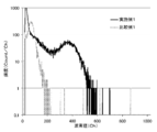
- FIG. 2 is a pulse height distribution spectrum when irradiated with alpha rays by the scintillator of Example 1.
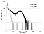
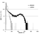
- FIG. 3 is a wave height distribution spectrum when irradiated with alpha rays by the scintillator of Example 2. It is a wave height distribution spectrum at the time of alpha ray irradiation by the scintillator of Example 3. It is a wave height distribution spectrum at the time of alpha ray irradiation by the scintillator of Example 4.
- It is the schematic of the radiation detector which consists of a scintillator and a gas amplification type detector.
- the scintillator of the present invention is represented by the chemical formula LiLu 1-x Nd x F 4 , and x is a numerical value in the range of 0.00001 to 0.2, and includes lithium neodymium-containing lithium lutetium fluoride (hereinafter referred to as Nd-containing fluoride). (Referred to as lithium lutetium iodide).
- Nd-containing fluoride lithium neodymium-containing lithium lutetium fluoride
- neodymium is a luminescent center element and is contained in the lithium lutetium fluoride by substituting a part of the lutetium of the lithium lutetium fluoride.
- x represents the content of neodymium.
- x When x is less than 0.00001, light emission becomes extremely weak and cannot be used as a scintillator. When x exceeds 0.2, for example, different compounds such as neodymium fluoride (NdF 3 ) are mixed, and the light emission characteristics tend to be deteriorated.
- the x is preferably in the range of 0.0001 to 0.05. By setting x to be 0.0001 or more, the probability of light emission through neodymium, which is the luminescent center element, is increased, and thus high emission intensity can be obtained. By setting x to 0.05 or less, it is possible to avoid a decrease in light emission due to concentration quenching.
- the scintillator made of Nd-containing lithium lutetium fluoride exhibits light emission based on the 5d-4f transition of neodymium by the incidence of radiation, it is possible to detect the radiation by detecting such light emission with a subsequent photodetector. It becomes. Since the scintillator has an emission wavelength of about 180 to 190 nm and gas ionization is efficiently performed in the gas amplification type detector, it can be combined with the gas amplification type detector as described above to form a radiation detector. it can.
- the emission intensity is extremely high as compared with a conventionally known scintillator that emits light in a vacuum ultraviolet region having a light emission wavelength of 200 nm or less, such as a scintillator made of lanthanum fluoride containing neodymium.
- the scintillator of the present invention made of Nd-containing lithium lutetium fluoride has an effective atomic number of 63 to 64 and a density of about 6.0 to 6.2 g / ml, both of which are extremely high. For this reason, the stopping power with respect to a high energy photon is excellent, and a high energy photon can be detected efficiently.
- the form of the Nd-containing lithium lutetium fluoride in the present invention is not particularly limited, and either crystal or glass can be used.
- This compound is generally produced as a crystal, and this crystal can obtain a particularly high emission intensity.
- a large-scale compound can be produced industrially by a melt growth method such as the Czochralski method or the Bridgeman method described later. It is preferable because it is easy to produce.
- the crystal of Nd-containing lithium lutetium fluoride has a lithium lutetium fluoride type crystal structure, is a tetragonal crystal belonging to the space group I41 / a, and can be easily identified by a technique such as powder X-ray diffraction. .
- the Nd-containing lithium lutetium fluoride used in the present invention is a colorless or slightly colored transparent solid and has good chemical stability. In normal use, performance deterioration in a short period of time is not observed. unacceptable. Furthermore, mechanical strength and workability are also good, and it is easy to process and use it in a desired shape.
- the shape of the scintillator is not particularly limited, but is generally used in a columnar or prismatic shape.
- the scintillator has an ultraviolet emitting surface (hereinafter also simply referred to as an ultraviolet emitting surface) facing a photodetector such as a gas amplification type detector in the subsequent stage of the radiation detector, and the ultraviolet emitting surface is subjected to optical polishing. It is preferable that By having such an ultraviolet emission surface, the ultraviolet rays generated by the scintillator can be efficiently incident on the subsequent photodetector.
- the shape of the ultraviolet light exit surface is not limited, and a shape suitable for the application, such as a quadrangle with a side length of several mm to several hundred mm square, or a circle with a diameter of several mm to several hundred mm is appropriately selected and used. be able to.
- the thickness of the scintillator with respect to the radiation incident direction varies depending on the type and energy of the radiation to be detected, but is generally several hundred ⁇ m to several hundred mm. It is preferable to apply an ultraviolet reflecting film made of aluminum, Teflon, or the like to the surface of the scintillator that does not face the photodetector, because it can prevent the dissipation of ultraviolet rays generated by the scintillator.
- the positional resolution of the radiation detector can be particularly enhanced by using a large number of scintillators provided with such an ultraviolet reflecting film.
- the scintillator of the present invention is not limited to radiation to be detected, and can be used for detection of radiation such as X-rays, ⁇ -rays, ⁇ -rays, ⁇ -rays, or neutrons. Since it has a number and density, it has the greatest effect in detecting high energy photons such as hard X-rays and ⁇ -rays.
- the production method of the Nd-containing lithium lutetium fluoride is not particularly limited, and can be produced by a known production method.
- the crystal is produced by a melt growth method such as a micro pull-down method, a Czochralski method, or a Bridgman method.
- the x value in the chemical formula LiLu 1-x Nd x F 4 can be adjusted to a desired value by adjusting the amount of lutetium and neodymium contained in the raw material during production.
- the Nd-containing lithium lutetium fluoride is a crystal
- segregation occurs, and there may be a difference between the amount of lutetium and neodymium contained in the raw material and the amount of lutetium and neodymium contained in the Nd-containing lithium lutetium fluoride. is there.
- a segregation coefficient is obtained in advance, and the amount of lutetium and neodymium contained in the raw material is adjusted by taking the segregation coefficient into consideration, so that an Nd-containing fluoride having a desired x value is obtained. Lithium lutetium can be obtained.
- Nd-containing lithium lutetium fluoride serving as a scintillator having excellent quality such as light emission characteristics.
- a crystal having a desired shape can be produced directly and in a short time.
- a large crystal having a diameter of several inches can be manufactured at low cost.
- an annealing operation may be performed after the production of the crystal in order to remove crystal defects caused by fluorine atom deficiency or thermal strain.
- a predetermined amount of raw material is filled into a crucible 5 having a hole at the bottom.
- the shape of the hole provided at the bottom of the crucible is not particularly limited, but is preferably a cylindrical shape having a diameter of 0.5 to 5 mm and a length of 0 to 2 mm.
- a metal fluoride such as lithium fluoride (LiF), lutetium fluoride (LuF 3 ), neodymium fluoride (NdF 3 ), or the like is used.
- the purity of the raw material is not particularly limited, but is preferably 99.99% or more. By using such a mixed raw material with high purity, the purity of the obtained Nd-containing lithium lutetium fluoride can be increased, and characteristics such as emission intensity are improved.
- the raw material may be a powdery or granular raw material, or may be used after being sintered or melted and solidified in advance.
- the crucible 5 filled with the raw material, the after heater 1, the heater 2, the heat insulating material 3, and the stage 4 are set as shown in FIG.
- the inside of the chamber 6 is evacuated to 1.0 ⁇ 10 ⁇ 3 Pa or less using a vacuum exhaust device, and then an inert gas such as high purity argon is introduced into the chamber to perform gas replacement.
- the pressure in the chamber after gas replacement is not particularly limited, but atmospheric pressure is common.
- a scavenger that is highly reactive with moisture.
- a solid scavenger such as zinc fluoride or a gas scavenger such as tetrafluoromethane can be suitably used.
- the method of mixing in a raw material beforehand is suitable, and when using a gas scavenger, the method of mixing in the said inert gas and introducing in a chamber is suitable. After performing the gas replacement operation, the raw material is heated and melted by the high frequency coil 7 and the heater 2.
- the heating method is not particularly limited, and for example, a resistance heating type carbon heater or the like can be appropriately used instead of the configuration of the high frequency coil and the heater.
- the melted raw material melt is drawn out from the hole at the bottom of the crucible using the pull-down rod 8 to start production of Nd-containing lithium lutetium fluoride.
- a metal wire at the tip of the pulling rod.
- the metal wire for example, a wire made of a W—Re alloy and having an outer diameter of about 0.5 mm can be preferably used.
- the desired crystal of Nd-containing lithium lutetium fluoride can be obtained by continuously pulling it down at a constant speed while appropriately adjusting the output of the high-frequency coil.
- the speed at which the pulling is continuously performed is not particularly limited, but is preferably in the range of 0.5 to 50 mm / hr because Nd-containing lithium lutetium fluoride without cracks can be obtained.
- the obtained Nd-containing lithium lutetium fluoride has good processability and can be easily processed into a desired shape.
- a known cutting machine such as a blade saw or a wire saw, a grinding machine, or a polishing machine can be used without any limitation.
- a scintillator made of Nd-containing lithium lutetium fluoride can be combined with a gas amplification type detector to form a radiation detector.
- a gas amplification type detector In addition to the microstrip gas chamber (MSGC) described in Patent Document 1, this gas amplification type detector is known in the art such as a multiwire proportional counter (MWPC) described in Non-Patent Document 2 and the like.
- MWPC multiwire proportional counter
- a gas amplification type detector can be used.
- Example 1 [Production of Nd-containing lithium lutetium fluoride] A crystal of Nd-containing lithium lutetium fluoride was manufactured using a crystal manufacturing apparatus using a micro-pulling-down method shown in FIG. As raw materials, lithium fluoride, lutetium fluoride, and neodymium fluoride having a purity of 99.99% or more were used.
- the after heater 1, the heater 2, the heat insulating material 3, the stage 4, and the crucible 5 are made of high-purity carbon, and the shape of the hole provided at the bottom of the crucible is 2.2 mm in diameter and 0.5 mm in length. It was made into the column shape.
- the respective raw materials were weighed and mixed well, and the obtained mixed raw material was filled in the crucible 5.
- the mixing ratio of the raw materials was 0.24 g of lithium fluoride, 2.1 g of lutetium fluoride, and 0.0018 g of neodymium fluoride.
- the crucible 5 filled with the raw material was set on the upper part of the after heater 1, and the heater 2 and the heat insulating material 3 were sequentially set around the crucible.
- the inside of the chamber 6 is evacuated to 5.0 ⁇ 10 ⁇ 4 Pa by using an evacuation apparatus composed of an oil rotary pump and an oil diffusion pump, and then a large amount of mixed gas of tetrafluoromethane and argon is introduced into the chamber 6.
- wavelength dispersive X-ray fluorescence measurement is performed on pellets having a known elemental ratio of neodymium to lutetium prepared by mixing a predetermined amount of lutetium fluoride and neodymium fluoride and press molding (hereinafter referred to as Nd / Lu). To create a calibration curve. For preparing such a calibration curve, five types of pellets having Nd / Lu of 0.0001 to 0.05 were used. Next, fluorescent X-ray measurement was performed on the pellets produced by pulverizing and press-molding the Nd-containing lithium lutetium fluoride crystals, and compared with the calibration curve.
- Nd / Lu of the Nd-containing lithium lutetium fluoride of this example was 0.0003.
- the Nd-containing lithium lutetium fluoride of this example is represented by the chemical formula LiLu 1-x Nd x F 4 , where x is 0.0003. It turns out that.
- the single crystal obtained by the production was cut into a length of 15 mm by a wire saw equipped with a diamond wire, and then ground and processed into a rectangular parallelepiped having a length of 15 mm, a width of 2 mm, and a thickness of 1 mm.
- a surface of the rectangular parallelepiped having a length of 15 mm and a width of 2 mm was used as an ultraviolet emitting surface, and the ultraviolet emitting surface was subjected to optical polishing to obtain a scintillator.
- the light emission characteristic when a hard X-ray was incident was measured by the following method. When carrying out the measurement, the inside of the apparatus was replaced with nitrogen.
- the scintillator was irradiated with hard X-rays using an encapsulated X-ray tube targeting tungsten.
- the tube voltage and tube current when generating hard X-rays from the encapsulated X-ray tube were 60 kV and 40 mA, respectively.
- the ultraviolet light generated from the ultraviolet light exit surface of the scintillator is condensed by a condensing mirror and is monochromatized by a spectroscope (manufactured by Spectrometer, KV201 type extreme ultraviolet spectrometer), and the intensity of light emission at each wavelength in the range of 150 to 280 nm is obtained. Recording was performed to obtain a spectrum of luminescence generated from the scintillator. The obtained emission spectrum is shown in FIG. As a result of the above measurement, it was confirmed that the scintillator of this example emitted extremely intense light at a wavelength of 183 nm by the incidence of hard X-rays.
- the pulse height distribution spectrum of the scintillator under alpha irradiation was measured by the following method. After the scintillator is bonded to the photocathode of a photomultiplier tube (R8778 manufactured by Hamamatsu Photonics Co., Ltd.), a 241 Am sealed radiation source having a radioactivity of 1 kBq can be provided on the surface opposite to the surface bonded to the photocathode of the crystal as much as possible. After installing the scintillator in a state where it was irradiated with alpha rays, the scintillator was shielded with a light shielding sheet so that no external light could enter.
- a photomultiplier tube R8778 manufactured by Hamamatsu Photonics Co., Ltd.
- the luminescence from the scintillator was converted into an electric signal through a photomultiplier tube to which a high voltage of 1300 V was applied.
- the electrical signal output from the photomultiplier tube is a pulse signal reflecting the light emission of the scintillator, and the pulse height of the pulse signal indicates the intensity of the light emission.
- the electric signal output from the photomultiplier tube was shaped and amplified by a shaping amplifier, and then input to a multiple wave height analyzer for analysis to create a wave height distribution spectrum. The created wave height distribution spectrum is shown in FIG.
- the horizontal axis of the wave height distribution spectrum represents the wave height value of the electric signal, that is, the intensity of light emitted from the scintillator.
- the vertical axis represents the frequency of the electrical signal indicating each peak value. In the region where the peak value of the peak distribution spectrum is about 370 channels, a clear peak due to scintillation light is seen, indicating that the scintillator of the present invention has sufficient emission intensity.
- Example 2 Nd-containing lithium lutetium fluoride was produced in the same manner as in Example 1 except that the mixing ratio of each raw material was 0.24 g of lithium fluoride, 2.1 g of lutetium fluoride, and 0.0091 g of neodymium fluoride. As a result of identifying the obtained crystal in the same manner as in Example 1, it was found that it was represented by the chemical formula LiLu 1-x Nd x F 4 and x was 0.002. The light emission characteristics of the scintillator were evaluated in the same manner as in Example 1. The obtained emission spectrum is shown in FIG. It was confirmed that the scintillator of this example emitted extremely intense light at a wavelength of 183 nm by the incidence of hard X-rays.
- the wave height distribution spectrum of the scintillator under alpha irradiation was measured in the same manner as in Example 1.
- the obtained wave height distribution spectrum is shown in FIG. In the region where the peak value of the peak distribution spectrum is about 410 channels, a clear peak due to scintillation light is seen, indicating that the scintillator of the present invention has sufficient emission intensity.
- Example 3 Nd-containing lithium lutetium fluoride was produced in the same manner as in Example 1, except that the mixing ratio of each raw material was 0.23 g of lithium fluoride, 2.1 g of lutetium fluoride, and 0.018 g of neodymium fluoride.
- the mixing ratio of each raw material was 0.23 g of lithium fluoride, 2.1 g of lutetium fluoride, and 0.018 g of neodymium fluoride.
- the obtained crystal in the same manner as in Example 1 it was represented by the chemical formula LiLu 1-x Nd x F 4 , and x was found to be 0.003.
- the light emission characteristics of the scintillator were evaluated in the same manner as in Example 1. The obtained emission spectrum is shown in FIG. It was confirmed that the scintillator of this example emitted extremely intense light at a wavelength of 183 nm by the incidence of hard X-rays.
- the wave height distribution spectrum of the scintillator under alpha irradiation was measured in the same manner as in Example 1.
- the obtained wave height distribution spectrum is shown in FIG. In the region where the peak value of the peak distribution spectrum is about 480 channels, a clear peak due to scintillation light is seen, indicating that the scintillator of the present invention has sufficient emission intensity.
- Example 4 Nd-containing lithium lutetium fluoride was produced in the same manner as in Example 1, except that the mixing ratio of each raw material was 0.23 g of lithium fluoride, 2.1 g of lutetium fluoride, and 0.054 g of neodymium fluoride.
- the mixing ratio of each raw material was 0.23 g of lithium fluoride, 2.1 g of lutetium fluoride, and 0.054 g of neodymium fluoride.
- the obtained crystal in the same manner as in Example 1 it was represented by the chemical formula LiLu 1-x Nd x F 4 , and x was found to be 0.01.
- the light emission characteristics of the scintillator were evaluated in the same manner as in Example 1. The obtained emission spectrum is shown in FIG. It was confirmed that the scintillator of this example emitted extremely intense light at a wavelength of 183 nm by the incidence of hard X-rays.
- the wave height distribution spectrum of the scintillator under alpha irradiation was measured in the same manner as in Example 1.
- the obtained wave height distribution spectrum is shown in FIG. In the region where the peak value of the peak distribution spectrum is about 360 channels, a clear peak due to scintillation light is seen, indicating that the scintillator of the present invention has sufficient emission intensity.
- Comparative Example 1 Production of lanthanum fluoride containing neodymium as the luminescent center element, and scintillator, except that the mixing ratio of each raw material is 2.0 g of lanthanum fluoride and 0.23 mg of neodymium fluoride. Fabrication was performed.
- the scintillator made of lanthanum fluoride containing neodymium is a conventionally known scintillator.
- the light emission characteristics of the scintillator were evaluated in the same manner as in Example 1.
- the obtained emission spectrum is shown in FIG.
- the wave height distribution spectrum of the scintillator under alpha irradiation was measured in the same manner as in Example 1.
- the obtained wave height distribution spectra are shown in FIGS.
- the peak value of the peak due to the scintillation light is about 70 channels, so that the scintillators of the present invention of Examples 1 to 4 have significantly higher emission intensity than the conventionally known scintillators. Recognize.
- Comparative Example 2 Fluoride containing neodymium as the luminescent center element in the same manner as in Example 1 except that the mixing ratio of each raw material was 0.86 g of barium fluoride, 0.13 g of lithium fluoride, and 0.0049 g of neodymium fluoride. Lithium barium was produced and a scintillator was produced. The scintillator made of lithium barium fluoride containing neodymium is a conventionally known scintillator. The light emission characteristics of the scintillator were evaluated in the same manner as in Example 1. The obtained emission spectrum is shown in FIG. From these results, it was found that according to the present invention, a scintillator having a significantly higher emission intensity than that of conventionally known scintillators can be obtained.
- Comparative Example 3 Production of lithium lutetium fluoride that does not contain neodymium, that is, x is 0, in the same manner as in Example 1 except that the mixing ratio of each raw material is 0.24 g of lithium fluoride and 2.1 g of lutetium fluoride.
- a scintillator was produced.
- the light emission characteristics of the scintillator were evaluated in the same manner as in Example 1.
- the obtained emission spectrum is shown in FIG. As a result, it was found that when x is less than 0.00001, light emission is extremely weak and cannot be used as a scintillator.
Landscapes
- Chemical & Material Sciences (AREA)
- Engineering & Computer Science (AREA)
- Materials Engineering (AREA)
- Organic Chemistry (AREA)
- Inorganic Chemistry (AREA)
- Crystallography & Structural Chemistry (AREA)
- Metallurgy (AREA)
- High Energy & Nuclear Physics (AREA)
- Physics & Mathematics (AREA)
- General Engineering & Computer Science (AREA)
- Health & Medical Sciences (AREA)
- Life Sciences & Earth Sciences (AREA)
- General Physics & Mathematics (AREA)
- Molecular Biology (AREA)
- Spectroscopy & Molecular Physics (AREA)
- Luminescent Compositions (AREA)
- Measurement Of Radiation (AREA)
Abstract
Description
放射線検出器は、放射線利用技術の重要な位置を占める要素技術であって、放射線利用技術の発展に伴い、検出感度、放射線の入射位置に対する位置分解能、或いは計数率特性について、より高度な性能が求められている。また、放射線利用技術の普及に伴い、放射線検出器の低コスト化、及び有感領域の大面積化も求められている。
該放射線検出器は、ネオジムを含有せしめたフッ化ランタン或いはネオジムを含有せしめたフッ化リチウムバリウムをシンチレーターとして用いた放射線検出器であり、入射した放射線を波長の短い真空紫外線に変換できるためガスの電離を効率よく行うことができる。しかし、該放射線検出器の検出感度等の性能をさらに向上させるためには、シンチレーターの発光強度を改善する必要があった。
本発明のシンチレーターとして用いたネオジムを含有するフッ化リチウムルテチウムについても、低エネルギーの光子を照射した際の発光特性については報告がなされているものの(非特許文献1参照)、高エネルギーの光子を照射した際の発光特性については報告例が無く、したがってシンチレーターとしての有用性は未知であった。
その結果、フッ化リチウムルテチウムに発光中心元素としてネオジムを含有せしめることによって、高エネルギーの光子に対する検出効率が高く、且つ、優れた発光強度を有するシンチレーターが得られることを見出し、本発明を完成するに至った。
下記化学式、
LiLu1-xNdxF4
〔式中、xは0.00001~0.2の数値を示す〕
で表わされる、ネオジムを含有するフッ化リチウムルテチウムからなることを特徴とするシンチレーターが提供される。
上記シンチレーターにおいて、
1)ネオジムを含有するフッ化リチウムルテチウムが単結晶であること、
2)シンチレーターが、高エネルギー光子用のシンチレーターであること
が好適である。
Nd含有フッ化リチウムルテチウムにおいて、ネオジムは発光中心元素であり、フッ化リチウムルテチウムのルテチウムの一部と置換することによって、フッ化リチウムルテチウムに含有されている。
xは、ネオジムの含有量を表わし、xが0.00001未満の場合には、発光がきわめて微弱となり、シンチレーターとしての使用に耐えない。xが0.2を超える場合には、例えばフッ化ネオジム(NdF3)等の異種の化合物が混入し、発光特性が低下する傾向にある。該xは0.0001~0.05の範囲とすることが好ましい。xを0.0001以上とすることによって、発光中心元素であるネオジムを介する発光の確率が高まり、したがって高い発光強度を得ることができる。xを0.05以下とすることによって、濃度消光による発光の減退を避けることができる。
当該シンチレーターは、発光波長が約180~190nmであり、ガス増幅型検出器において、ガスの電離が効率よく行われるので、前記したようなガス増幅型検出器と組み合わせて放射線検出器をなすことができる。また、ネオジムを含有するフッ化ランタンからなるシンチレーター等の従来知られている発光波長が200nm以下の真空紫外領域で発光するシンチレーターに比較して、発光強度が極めて高い。
有効原子番号=(ΣWiZi 4)1/4
式中、Wi及びZiは、それぞれシンチレーターを構成する元素のうちのi番目の元素の質量分率及び原子番号である。
Nd含有フッ化リチウムルテチウムの結晶は、フッ化リチウムルテチウム型の結晶構造を有し、空間群I41/aに属する正方晶であって、粉末X線回折等の手法によって容易に同定することができる。結晶の中でも単結晶のものを用いることが特に好ましい。単結晶を用いることによって、粒界における光の散逸や非輻射遷移による損失を生じることなく高い発光強度を得ることができる。
本発明で使用するNd含有フッ化リチウムルテチウムは、無色ないしはわずかに着色した透明な固体であり、良好な化学的安定性を有しており、通常の使用においては短期間での性能の劣化は認められない。更に、機械的強度及び加工性も良好であり、所望の形状に加工して用いることが容易である。
シンチレーターの放射線入射方向に対する厚さは、検出対象とする放射線の種類及びエネルギーによって異なるが、一般に数百μm~数百mmである。
シンチレーターの光検出器に対向しない面に、アルミニウム或いはテフロン等からなる紫外線反射膜を施すことは、シンチレーターで生じた紫外線の散逸を防止することができるため、好ましい態様である。また、かかる紫外線反射膜が施されたシンチレーターを多数配列して用いることにより、放射線検出器の位置分解能を特に高めることができる。
なお、前記化学式LiLu1-xNdxF4中のx値は、製造する際の原料に含まれるルテチウム及びネオジムの量を調整することにより、所望の値に調整することができる。Nd含有フッ化リチウムルテチウムが結晶である場合には、偏析が起こり、原料に含まれるルテチウム及びネオジムの量とNd含有フッ化リチウムルテチウム含まれるルテチウム及びネオジムの量との間に差異が生じる場合がある。しかし、かかる偏析が起こる場合においても、予め偏析係数を求めておき、当該偏析係数を加味して原料に含まれるルテチウム及びネオジムの量を調整することにより、所望のx値を有するNd含有フッ化リチウムルテチウムを得ることができる。
まず、所定量の原料を、底部に孔を設けた坩堝5に充填する。坩堝底部に設ける孔の形状は、特に限定されないが、直径が0.5~5mm、長さが0~2mmの円柱状とすることが好ましい。
原料としては、フッ化リチウム(LiF)、フッ化ルテチウム(LuF3)、フッ化ネオジム(NdF3)等の金属フッ化物が用いられる。かかる原料の純度は特に限定されないが、99.99%以上とすることが好ましい。このような純度の高い混合原料を用いることにより、得られるNd含有フッ化リチウムルテチウムの純度を高めることができ、発光強度等の特性が向上する。原料は、粉末状あるいは粒状の原料を用いても良く、あらかじめ焼結或いは溶融固化させてから用いても良い。
上記ガス置換操作によっても除去できない水分による悪影響を避けるため、水分との反応性の高いスカベンジャーを用いて、水分を除去することが好ましい。かかるスカベンジャーとしては、フッ化亜鉛等の固体スカベンジャー或いは四フッ化メタン等の気体スカベンジャーを好適に用いることができる。なお、固体スカベンジャーを用いる場合には原料中に予め混合しておく方法が好適であり、気体スカベンジャーを用いる場合には上記不活性ガスに混合してチャンバー内に導入する方法が好適である。
ガス置換操作を行った後、高周波コイル7、及びヒーター2によって原料を加熱して溶融せしめる。加熱方法は特に限定されず、例えば上記高周波コイルとヒーターの構成に替えて、抵抗加熱式のカーボンヒーター等を適宜用いることができる。
Nd含有フッ化リチウムルテチウムの製造を開始した後、高周波コイルの出力を適宜調整しながら一定の速度で連続的に引き下げることにより、所期のNd含有フッ化リチウムルテチウムの結晶を得ることができる。かかる連続的に引き下げる際の速度は、特に限定されないが、0.5~50mm/hrの範囲とすることによって、クラックのないNd含有フッ化リチウムルテチウムを得ることができるため好ましい。
〔Nd含有フッ化リチウムルテチウムの製造〕
図2に示すマイクロ引下げ法による結晶製造装置を用いて、Nd含有フッ化リチウムルテチウムの結晶を製造した。原料としては、純度が99.99%以上のフッ化リチウム、フッ化ルテチウム、及びフッ化ネオジムを用いた。なお、アフターヒーター1、ヒーター2、断熱材3、ステージ4、及び坩堝5は、高純度カーボン製のものを使用し、坩堝底部に設けた孔の形状は直径2.2mm、長さ0.5mmの円柱状とした。
まず、前記各原料をそれぞれ秤量し、よく混合し、得られた混合原料を坩堝5に充填した。なお、各原料の混合比は、フッ化リチウム 0.24g、フッ化ルテチウム 2.1g、及びフッ化ネオジム 0.0018gとした。
原料を充填した坩堝5を、アフターヒーター1の上部にセットし、その周囲にヒーター2、及び断熱材3を順次セットした。次いで、油回転ポンプ及び油拡散ポンプからなる真空排気装置を用いて、チャンバー6内を5.0×10⁻⁴Paまで真空排気した後、四フッ化メタン-アルゴン混合ガスをチャンバー6内に大気圧まで導入し、ガス置換を行った。
高周波コイル7に高周波電流を印加し、誘導加熱によって原料を加熱して溶融せしめ、引き下げロッド8の先端に設けたW-Reワイヤーを、坩堝5底部の孔上記孔に挿入し、原料の融液を上記孔より引き下げ、結晶化を開始した。高周波の出力を調整しながら、3mm/hrの速度で連続的に引き下げ、結晶を得た。該結晶は直径が2.2mmであり、白濁やクラックの無い良質な単結晶であった。
上記製造によって得られたNd含有フッ化リチウムルテチウムの結晶を粉砕して粉末にし、粉末X線回折測定に供した。粉末X線回折法によって得られた回折パターンを解析した結果から、本実施例のシンチレーターはフッ化リチウムルテチウム型の結晶のみからなることが分かった。
上記粉砕した粉末をプレス成型してペレットにし、蛍光X線測定に供した。なお、分析装置はパナリティカル社製波長分散型蛍光X線測定装置Axiosを用い、分光素子にはパナリティカル社製PX10を用いた。
まず、所定量のフッ化ルテチウム及びフッ化ネオジムを混合し、プレス成型して作製したルテチウムに対するネオジムの元素比(以下、Nd/Luと表わす)が既知のペレットについて、波長分散型蛍光X線測定を行い、検量線を作成した。かかる検量線の作成には、Nd/Luが0.0001~0.05の5種のペレットを用いた。次いで、前記Nd含有フッ化リチウムルテチウムの結晶を粉砕し、プレス成型して作製したペレットについて、蛍光X線測定を行い、前記検量線と比較した。その結果、本実施例のNd含有フッ化リチウムルテチウムのNd/Luは、0.0003であった。
前記粉末X線回折測定、及び蛍光X線測定の結果から、本実施例のNd含有フッ化リチウムルテチウムは化学式LiLu1-xNdxF4で表わされ、当該式中のxは0.0003であることが分かった。
前記製造によって得られた単結晶を、ダイヤモンドワイヤーを備えたワイヤーソーによって15mmの長さに切断した後、研削し、長さ15mm、幅2mm、厚さ1mmの直方体に加工した。かかる直方体の長さ15mm、幅2mmの面を紫外線出射面とし、当該紫外線出射面に光学研磨を施して、シンチレーターを得た。
このシンチレーターについて、硬X線を入射した際の発光特性を以下の方法によって測定した。なお、測定を実施する際には、装置内部を窒素で置換した。
タングステンをターゲットとする封入式X線管球を用いて、硬X線をシンチレーターに照射した。封入式X線管球より硬X線を発生させる際の管電圧及び管電流はそれぞれ60kV及び40mAとした。シンチレーターの紫外線出射面より生じた紫外線を集光ミラーで集光し、分光器(分光計器製、KV201型極紫外分光器)にて単色化し、150~280nmの範囲の各波長における発光の強度を記録してシンチレーターより生じた発光のスペクトルを得た。得られた発光のスペクトルを図1に示す。
上記測定の結果、本実施例のシンチレーターは、硬X線の入射によって、波長183nmにおいて極めて強く発光することが確認された。
シンチレーターを光電子増倍管(浜松ホトニクス社製 R8778)の光電面に接着した後、1kBqの放射能を有する241Am密封線源を該結晶の光電面と接着している面と逆の面のできるだけ近い位置に設置し、シンチレーターにアルファ線を照射した状態とした後、外部からの光が入らないように遮光シートで遮光した。次いで、該シンチレーターより発せられた発光を計測するため、1300Vの高電圧を印加した光電子増倍管を介して、シンチレーターからの発光を電気信号に変換した。ここで、光電子増倍管より出力される電気信号は、シンチレーターの発光を反映したパルス状の信号であり、当該パルス状の信号の波高は発光の強度を表す。
かかる光電子増倍管より出力された電気信号を整形増幅器で整形、増幅した後、多重波高分析器に入力して解析し、波高分布スペクトルを作成した。作成した波高分布スペクトルを図3に示す。該波高分布スペクトルの横軸は、電気信号の波高値すなわちシンチレーターの発光の強度を表している。また、縦軸は各波高値を示した電気信号の頻度を表している。
該波高分布スペクトルの波高値が約370チャンネルの領域において、シンチレーション光による明瞭なピークが見られ、本発明のシンチレーターが充分な発光強度を有することがわかる。
各原料の混合比をフッ化リチウム 0.24g、フッ化ルテチウム 2.1g、及びフッ化ネオジム 0.0091gとする以外は、実施例1と同様にしてNd含有フッ化リチウムルテチウムを製造した。実施例1と同様にして、得られた結晶の同定を行った結果、化学式LiLu1-xNdxF4で表わされ、xは0.002であることが分かった。
実施例1と同様にしてシンチレーターの発光特性を評価した。得られた発光のスペクトルを図1に示す。本実施例のシンチレーターは、硬X線の入射によって、波長183nmにおいて極めて強く発光することが確認された。
実施例1と同様にしてシンチレーターのアルファ線照射下における波高分布スペクトルを測定した。得られた波高分布スペクトルを図4に示す。該波高分布スペクトルの波高値が約410チャンネルの領域において、シンチレーション光による明瞭なピークが見られ、本発明のシンチレーターが充分な発光強度を有することがわかる。
各原料の混合比をフッ化リチウム 0.23g、フッ化ルテチウム 2.1g、及びフッ化ネオジム 0.018gとする以外は、実施例1と同様にしてNd含有フッ化リチウムルテチウムを製造した。実施例1と同様にして、得られた結晶の同定を行った結果、化学式LiLu1-xNdxF4で表わされ、xは0.003であることが分かった。
実施例1と同様にしてシンチレーターの発光特性を評価した。得られた発光のスペクトルを図1に示す。本実施例のシンチレーターは、硬X線の入射によって、波長183nmにおいて極めて強く発光することが確認された。
実施例1と同様にしてシンチレーターのアルファ線照射下における波高分布スペクトルを測定した。得られた波高分布スペクトルを図5に示す。該波高分布スペクトルの波高値が約480チャンネルの領域において、シンチレーション光による明瞭なピークが見られ、本発明のシンチレーターが充分な発光強度を有することがわかる。
各原料の混合比をフッ化リチウム 0.23g、フッ化ルテチウム 2.1g、及びフッ化ネオジム 0.054gとする以外は、実施例1と同様にしてNd含有フッ化リチウムルテチウムを製造した。実施例1と同様にして、得られた結晶の同定を行った結果、化学式LiLu1-xNdxF4で表わされ、xは0.01であることが分かった。
実施例1と同様にしてシンチレーターの発光特性を評価した。得られた発光のスペクトルを図1に示す。本実施例のシンチレーターは、硬X線の入射によって、波長183nmにおいて極めて強く発光することが確認された。
実施例1と同様にしてシンチレーターのアルファ線照射下における波高分布スペクトルを測定した。得られた波高分布スペクトルを図6に示す。該波高分布スペクトルの波高値が約360チャンネルの領域において、シンチレーション光による明瞭なピークが見られ、本発明のシンチレーターが充分な発光強度を有することがわかる。
各原料の混合比をフッ化ランタン 2.0g、及びフッ化ネオジム 0.23mgとする以外は、実施例1と同様にして、発光中心元素としてネオジムを含有するフッ化ランタンの製造、並びにシンチレーターの作製を行った。該ネオジムを含有するフッ化ランタンからなるシンチレーターは、従来公知のシンチレーターである。
実施例1と同様にしてシンチレーターの発光特性を評価した。得られた発光のスペクトルを図1に示す。
実施例1と同様にしてシンチレーターのアルファ線照射下における波高分布スペクトルを測定した。得られた波高分布スペクトルを図3~6に示す。
当該波高分布スペクトルにおいて、シンチレーション光によるピークの波高値は約70チャンネルであることから、実施例1~4の本発明のシンチレーターは従来公知のシンチレーターに比較して大幅に高い発光強度を有することがわかる。
各原料の混合比をフッ化バリウム 0.86g、フッ化リチウム 0.13g、及びフッ化ネオジム 0.0049gとする以外は、実施例1と同様にして、発光中心元素としてネオジムを含有するフッ化リチウムバリウムの製造、並びにシンチレーターの作製を行った。該ネオジムを含有するフッ化リチウムバリウムからなるシンチレーターは、従来公知のシンチレーターである。
実施例1と同様にしてシンチレーターの発光特性を評価した。得られた発光のスペクトルを図1に示す。
これらの結果から、本発明によれば、従来公知のシンチレーターに比較して発光強度が大幅に高いシンチレーターが得られることが分かった。
各原料の混合比をフッ化リチウム 0.24g、及びフッ化ルテチウム 2.1gとする以外は、実施例1と同様にして、ネオジムを含有しない、すなわちxが0であるフッ化リチウムルテチウムの製造、並びにシンチレーターの作製を行った。
実施例1と同様にしてシンチレーターの発光特性を評価した。得られた発光のスペクトルを図1に示す。その結果、xが0.00001未満の場合には、発光がきわめて微弱となり、シンチレーターとしての使用に耐えないことが分かった。
2 ヒーター
3 断熱材
4 ステージ
5 坩堝
6 チャンバー
7 高周波コイル
Claims (3)
- 下記化学式、
LiLu1-xNdxF4
〔式中、xは0.00001~0.2の数値を示す〕
で表わされる、ネオジムを含有するフッ化リチウムルテチウムからなることを特徴とするシンチレーター。 - ネオジムを含有するフッ化リチウムルテチウムが、単結晶であることを特徴とする請求項1に記載のシンチレーター。
- シンチレーターが、高エネルギー光子用のシンチレーターであることを特徴とする請求項1または2に記載のシンチレーター。
Priority Applications (5)
| Application Number | Priority Date | Filing Date | Title |
|---|---|---|---|
| EP10783368A EP2439252A1 (en) | 2009-06-03 | 2010-06-01 | Scintillator |
| CN2010800243037A CN102459508A (zh) | 2009-06-03 | 2010-06-01 | 闪烁体 |
| CA2763329A CA2763329A1 (en) | 2009-06-03 | 2010-06-01 | Scintillator |
| US13/376,106 US20120074356A1 (en) | 2009-06-03 | 2010-06-01 | Scintillator |
| JP2011518452A JP5575123B2 (ja) | 2009-06-03 | 2010-06-01 | シンチレーター |
Applications Claiming Priority (2)
| Application Number | Priority Date | Filing Date | Title |
|---|---|---|---|
| JP2009-134323 | 2009-06-03 | ||
| JP2009134323 | 2009-06-03 |
Publications (1)
| Publication Number | Publication Date |
|---|---|
| WO2010140585A1 true WO2010140585A1 (ja) | 2010-12-09 |
Family
ID=43297719
Family Applications (1)
| Application Number | Title | Priority Date | Filing Date |
|---|---|---|---|
| PCT/JP2010/059263 Ceased WO2010140585A1 (ja) | 2009-06-03 | 2010-06-01 | シンチレーター |
Country Status (7)
| Country | Link |
|---|---|
| US (1) | US20120074356A1 (ja) |
| EP (1) | EP2439252A1 (ja) |
| JP (1) | JP5575123B2 (ja) |
| KR (1) | KR20120036305A (ja) |
| CN (1) | CN102459508A (ja) |
| CA (1) | CA2763329A1 (ja) |
| WO (1) | WO2010140585A1 (ja) |
Cited By (1)
| Publication number | Priority date | Publication date | Assignee | Title |
|---|---|---|---|---|
| WO2012032816A1 (ja) * | 2010-09-10 | 2012-03-15 | 株式会社トクヤマ | 放射線画像検出器 |
Families Citing this family (4)
| Publication number | Priority date | Publication date | Assignee | Title |
|---|---|---|---|---|
| CN103194796A (zh) * | 2013-03-22 | 2013-07-10 | 中国科学院上海光学精密机械研究所 | 钬镨共掺氟化镥锂中红外激光晶体及其制备方法 |
| CN103820855B (zh) * | 2014-02-20 | 2016-11-16 | 宁波大学 | 一种用于白光LED的Tb3 +/Sm3 +掺杂LiLuF4单晶体及其制备方法 |
| US10393887B2 (en) * | 2015-07-19 | 2019-08-27 | Afo Research, Inc. | Fluorine resistant, radiation resistant, and radiation detection glass systems |
| US20200041666A1 (en) * | 2018-08-06 | 2020-02-06 | Wisconsin Alumni Research Foundation | Semiconductor membrane enabled hard x-ray detectors |
Citations (2)
| Publication number | Priority date | Publication date | Assignee | Title |
|---|---|---|---|---|
| JP2007532746A (ja) * | 2004-04-14 | 2007-11-15 | サン−ゴバン クリストー エ デテクトゥール | 核バックグラウンドノイズの低減を伴う希土類系シンチレーター材料 |
| WO2008093553A1 (ja) * | 2007-02-01 | 2008-08-07 | Konica Minolta Medical & Graphic, Inc. | 放射線画像変換パネルの製造方法、および放射線画像変換パネル |
-
2010
- 2010-06-01 KR KR1020117028877A patent/KR20120036305A/ko not_active Withdrawn
- 2010-06-01 JP JP2011518452A patent/JP5575123B2/ja not_active Expired - Fee Related
- 2010-06-01 WO PCT/JP2010/059263 patent/WO2010140585A1/ja not_active Ceased
- 2010-06-01 EP EP10783368A patent/EP2439252A1/en not_active Withdrawn
- 2010-06-01 CN CN2010800243037A patent/CN102459508A/zh active Pending
- 2010-06-01 US US13/376,106 patent/US20120074356A1/en not_active Abandoned
- 2010-06-01 CA CA2763329A patent/CA2763329A1/en not_active Abandoned
Patent Citations (2)
| Publication number | Priority date | Publication date | Assignee | Title |
|---|---|---|---|---|
| JP2007532746A (ja) * | 2004-04-14 | 2007-11-15 | サン−ゴバン クリストー エ デテクトゥール | 核バックグラウンドノイズの低減を伴う希土類系シンチレーター材料 |
| WO2008093553A1 (ja) * | 2007-02-01 | 2008-08-07 | Konica Minolta Medical & Graphic, Inc. | 放射線画像変換パネルの製造方法、および放射線画像変換パネル |
Non-Patent Citations (3)
| Title |
|---|
| P. SCHOTANUS ET AL., NUCLEAR INSTRUMENTS AND METHODS IN PHYSICS RESEARCH, vol. A272, 1988, pages 913 - 916 |
| RANIERI, I.M.: "Growth of LiY1-XLuXF4 crystals under CF4 atmosphere", JOURNAL OF ALLOYS AND COMPOUNDS, vol. 344, 2002, pages 203 - 206, XP004387067 * |
| SEMASHKO, V.V. ET AL.: "Regarding the possibilities of upconversion UV and VUV lasers based on 5d-4f transitions of rare-earth ions in wide-bandgap dielectric crystals", PROCEEDINGS OF SPIE-THE INTERNATIONAL SOCIETY FOR OPTICAL ENGINEERING, vol. 4061, 2000, pages 306 - 316 |
Cited By (1)
| Publication number | Priority date | Publication date | Assignee | Title |
|---|---|---|---|---|
| WO2012032816A1 (ja) * | 2010-09-10 | 2012-03-15 | 株式会社トクヤマ | 放射線画像検出器 |
Also Published As
| Publication number | Publication date |
|---|---|
| EP2439252A1 (en) | 2012-04-11 |
| CA2763329A1 (en) | 2010-12-09 |
| CN102459508A (zh) | 2012-05-16 |
| JP5575123B2 (ja) | 2014-08-20 |
| US20120074356A1 (en) | 2012-03-29 |
| KR20120036305A (ko) | 2012-04-17 |
| JPWO2010140585A1 (ja) | 2012-11-22 |
Similar Documents
| Publication | Publication Date | Title |
|---|---|---|
| JP5378356B2 (ja) | 中性子検出用シンチレーターおよび中性子検出装置 | |
| EP2671940B1 (en) | Garnet type crystal for scintillator and radiation detector using same | |
| JP5460067B2 (ja) | 放射線検出装置 | |
| US20130181137A1 (en) | Neutron Radiation Detector, Neutron Radiation Detection Scintillator and Method for Discriminating Between Neutron Radiation and Gamma Radiation | |
| JP5575123B2 (ja) | シンチレーター | |
| CN103403126B (zh) | 闪烁体、放射线检测装置及放射线检测方法 | |
| Fujimoto et al. | Lithium aluminate crystals as scintillator for thermal neutron detection | |
| WO2012060381A1 (ja) | コルキライト型結晶、中性子検出用シンチレーター及び中性子線検出器 | |
| JP5634285B2 (ja) | コルキライト型結晶、中性子検出用シンチレーター及び中性子線検出器 | |
| EP2679652A1 (en) | Scintillator for neutron detection, and neutron radiation detector | |
| JP5729954B2 (ja) | フッ化物単結晶、シンチレーター及びフッ化物単結晶の製造方法 | |
| JP5737978B2 (ja) | 中性子検出用シンチレーター及び中性子線検出器 | |
| RU2467354C1 (ru) | Быстрый сцинтилляционный материал на основе фторида бария и способ его получения (варианты) | |
| JP2012185025A (ja) | 放射線画像検出器 | |
| WO2013161227A1 (ja) | 金属フッ化物結晶、発光素子、シンチレーター、中性子の検出方法及び金属フッ化物結晶の製造方法 | |
| WO2011078243A1 (ja) | 金属フッ化物結晶、真空紫外発光素子及び真空紫外発光シンチレーター | |
| JP2012162596A (ja) | 中性子検出用シンチレーター及び中性子線検出器 | |
| WO2012026584A1 (ja) | 中性子検出用シンチレーター及び中性子線検出器 | |
| WO2012026585A1 (ja) | フッ化物結晶、放射線検出用シンチレーター及び放射線検出器 | |
| JP2011190393A (ja) | 真空紫外発光素子及びシンチレーター |
Legal Events
| Date | Code | Title | Description |
|---|---|---|---|
| WWE | Wipo information: entry into national phase |
Ref document number: 201080024303.7 Country of ref document: CN |
|
| 121 | Ep: the epo has been informed by wipo that ep was designated in this application |
Ref document number: 10783368 Country of ref document: EP Kind code of ref document: A1 |
|
| WWE | Wipo information: entry into national phase |
Ref document number: 2011518452 Country of ref document: JP |
|
| WWE | Wipo information: entry into national phase |
Ref document number: 2763329 Country of ref document: CA Ref document number: 2010783368 Country of ref document: EP |
|
| ENP | Entry into the national phase |
Ref document number: 20117028877 Country of ref document: KR Kind code of ref document: A |
|
| WWE | Wipo information: entry into national phase |
Ref document number: 13376106 Country of ref document: US |
|
| NENP | Non-entry into the national phase |
Ref country code: DE |