WO2010143340A1 - 空気調和システム診断装置及び空気調和システム診断結果表示装置 - Google Patents
空気調和システム診断装置及び空気調和システム診断結果表示装置 Download PDFInfo
- Publication number
- WO2010143340A1 WO2010143340A1 PCT/JP2010/001725 JP2010001725W WO2010143340A1 WO 2010143340 A1 WO2010143340 A1 WO 2010143340A1 JP 2010001725 W JP2010001725 W JP 2010001725W WO 2010143340 A1 WO2010143340 A1 WO 2010143340A1
- Authority
- WO
- WIPO (PCT)
- Prior art keywords
- communication
- diagnosis
- unit
- air conditioning
- conditioning system
- Prior art date
- Legal status (The legal status is an assumption and is not a legal conclusion. Google has not performed a legal analysis and makes no representation as to the accuracy of the status listed.)
- Ceased
Links
Images


Classifications
-
- F—MECHANICAL ENGINEERING; LIGHTING; HEATING; WEAPONS; BLASTING
- F24—HEATING; RANGES; VENTILATING
- F24F—AIR-CONDITIONING; AIR-HUMIDIFICATION; VENTILATION; USE OF AIR CURRENTS FOR SCREENING
- F24F11/00—Control or safety arrangements
- F24F11/30—Control or safety arrangements for purposes related to the operation of the system, e.g. for safety or monitoring
- F24F11/32—Responding to malfunctions or emergencies
- F24F11/38—Failure diagnosis
-
- G—PHYSICS
- G05—CONTROLLING; REGULATING
- G05G—CONTROL DEVICES OR SYSTEMS INSOFAR AS CHARACTERISED BY MECHANICAL FEATURES ONLY
- G05G5/00—Means for preventing, limiting or returning the movements of parts of a control mechanism, e.g. locking controlling member
- G05G5/06—Means for preventing, limiting or returning the movements of parts of a control mechanism, e.g. locking controlling member for holding members in one or a limited number of definite positions only
-
- F—MECHANICAL ENGINEERING; LIGHTING; HEATING; WEAPONS; BLASTING
- F24—HEATING; RANGES; VENTILATING
- F24F—AIR-CONDITIONING; AIR-HUMIDIFICATION; VENTILATION; USE OF AIR CURRENTS FOR SCREENING
- F24F11/00—Control or safety arrangements
- F24F11/50—Control or safety arrangements characterised by user interfaces or communication
- F24F11/52—Indication arrangements, e.g. displays
-
- F—MECHANICAL ENGINEERING; LIGHTING; HEATING; WEAPONS; BLASTING
- F24—HEATING; RANGES; VENTILATING
- F24F—AIR-CONDITIONING; AIR-HUMIDIFICATION; VENTILATION; USE OF AIR CURRENTS FOR SCREENING
- F24F11/00—Control or safety arrangements
- F24F11/50—Control or safety arrangements characterised by user interfaces or communication
- F24F11/54—Control or safety arrangements characterised by user interfaces or communication using one central controller connected to several sub-controllers
Definitions
- the present invention relates to an air conditioning system diagnostic device and an air conditioning system diagnostic result display device for performing diagnosis on an air conditioning system in which a plurality of air conditioners are connected by refrigerant piping and a general-purpose network and displaying the diagnosis result. It is.
- a failure is detected and expressed by a diagram (hereinafter referred to as a system system diagram) showing the device configuration of the air conditioning system.
- An air conditioner installation work support device has been proposed (see, for example, Patent Document 1).
- a centralized control device for an air conditioning system that automatically obtains a device configuration and generates a system diagram by inquiring an outdoor unit or remote controller connected to each indoor unit is proposed. (For example, refer to Patent Document 2).
- the present invention has been made to solve the above-described problem, and generates a system diagram representing the air conditioning system in a different format according to the detected malfunction, and displays the malfunction using this system diagram.
- An object of the present invention is to provide an air conditioning system diagnostic device and an air conditioning system diagnostic result display device capable of expressing various problems with high visibility.
- An air conditioning system diagnostic apparatus is an air conditioning system in which a plurality of devices are connected via a network, and the related devices transmit and receive control signals and the like via the network.
- a communication list configured by a combination of a communication unit that performs communication, a device type recognition unit that recognizes a device type indicating the type of the device, and a communication source and a communication destination device such as the control signal Communication list generation means, system system analysis means for deriving system system information representing the equipment configuration of the air conditioning system from the equipment type and the communication list, and information of the air conditioning system from information acquired via the communication means.
- a system system diagram is generated, and a diagnostic result superimposed diagram generation unit that emphasizes and superimposes the contents of the diagnostic result on the system system diagram, and the diagnostic result superimposed diagram generation unit And a display for acquiring and displaying the system diagram on which the contents of the diagnosis result are superimposed.
- the air conditioning system diagnostic device of the present invention since the diagnostic result of the air conditioning system is superimposed on the system diagram representing the air conditioning system, the correspondence between the diagnostic result and the air conditioning system is displayed. Can be easily visually recognized, and by this, it is possible to quickly cope with the problem and solve the problem at an early stage.
- FIG. 1 shows the internal block of the air conditioning system diagnostic apparatus 100 which concerns on Embodiment 1 of this invention, and the whole structure of an air conditioning system. It is an internal block diagram of the outdoor unit 10a and the indoor unit 10b in the air conditioning system which concerns on Embodiment 1 of this invention. It is a flowchart which shows the process of the air conditioning system diagnostic apparatus 100 which concerns on Embodiment 1 of this invention. It is a figure which shows the system system diagram which connected between the main apparatuses displayed on the display panel 181 of the air conditioning system diagnostic apparatus 100 which concerns on Embodiment 1 of this invention with the line. It is the figure which highlighted the refrigerant system which connects between each apparatus displayed on the display panel.
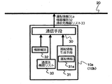
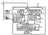
- FIG. 1 is a diagram showing an overall configuration of an internal block and an air conditioning system of an air conditioning system diagnostic apparatus 100 according to Embodiment 1 of the present invention.
- a plurality of air conditioners 10 including at least an outdoor unit 10 a and one or more indoor units 10 b are connected to a network 20.
- an air conditioning system diagnostic apparatus 100 that diagnoses a malfunction of the air conditioning system is connected to the network 20.
- FIG. 1 although the structure by which the some air conditioner 10 is connected to the network 20 is shown, it is not restricted to this, It is good also as what one air conditioner 10 is connected. .
- the air-conditioning system diagnosis apparatus 100 includes at least the following component groups (1) to (4).
- Component group for acquiring data flowing through the network 20 (2) Component group for diagnosing the state of the air conditioning system (3) Component group (4) for analyzing the system system of the air conditioning system (2) Constituent Element Group Displaying Combined Diagnosis Results and System System in (3)
- the constituent element groups (1) to (4) are further configured by the following constituent elements.
- the communication device 110 is connected to the network 20 and transmits and receives data from the network 20.
- the component group according to (2) is the operation information 31a (in the description of FIG. 2) held by the outdoor unit 10a or the indoor unit 10b constituting the air conditioner 10.
- the operation information acquisition means 120 is acquired via the network 20 and the communication means 110.
- the component group which concerns on (2) has the system diagnosis means 130 which diagnoses the state of an air conditioning system based on the driving information 31a acquired by this driving information acquisition means 120.
- the system diagnosis unit 130 includes a refrigeration cycle analysis unit 131 that performs a diagnosis of the state of the refrigeration cycle in the air conditioning system based on the acquired operation information 31a and derives a refrigeration cycle diagnosis result (described later in the description of FIG. 3). I have.
- the refrigeration cycle analysis means 131 has a refrigeration cycle analysis rule 131a for deriving the above refrigeration cycle diagnosis result.
- the component group according to (3) is the device type 32 (explanation of FIG. 2) possessed by the outdoor unit 10a or the indoor unit 10b constituting the air conditioner 10.
- Device type recognizing means 140 that acquires the information via the network 20 and the communication means 110.
- the component group according to (3) includes a communication destination device list 33 (described later in the description of FIG. 2) held by the outdoor unit 10a or the indoor unit 10b that configures the air conditioner 10, the network 20 and the communication unit.
- the communication list generation unit 150 acquires the information via the communication list 110.
- the component group according to (3) includes the device type 32 acquired by the device type recognition unit 140 and the communication list generated by the communication list generation unit 150 (described later in the description of FIG. 3).
- the system system analysis means 160 for deriving system system information (described later in the description of FIG. 3) including the refrigerant system of the air conditioning system and the interlocking relationship is included.
- the system system analysis means 160 has a system system analysis rule 160a for deriving system system information.
- the component group in (4) is based on the system system information derived by the system system analysis means 160.
- a system system diagram (described later in the description of FIG. 3) constituted by icons of the outdoor unit 10a, the indoor unit 10b, and the like and lines connecting them is generated, and the refrigeration cycle diagnosis result derived by the refrigeration cycle analysis unit 131 is generated.
- the diagnostic system has a diagnostic result superimposition diagram generation means 170 that superimposes in the vicinity of the icon of the related device in the system system diagram.
- the component group which concerns on (4) has the indicator 180 which displays the system system diagram on which the content of the refrigerating cycle diagnostic result was superimposed.
- the diagnostic result superimposed diagram generation means 170 has an inter-device main connection determination rule 170a and a diagnostic result corresponding system system diagram generation rule 170b for generating a system system diagram.
- FIG. 2 is an internal block diagram of the outdoor unit 10a and the indoor unit 10b in the air-conditioning system according to Embodiment 1 of the present invention.
- the outdoor unit 10 a and the indoor unit 10 b are connected to a network 20 and include a communication unit 30 that transmits and receives data from the network 20.
- the outdoor unit 10a and the indoor unit 10b include an operation information generation unit 31 that generates operation information 31a such as a refrigerant temperature value or a refrigerant pressure value.
- the outdoor unit 10a and the indoor unit 10b have a device type 32 indicating the device type or function, and a communication destination device list 33 that is a list of communication destinations such as control signals.
- the communication unit 30 sends the operation information 31 a generated by the operation information generation unit 31, the device type 32, and the communication destination device list 33 to the network 20.
- the outdoor unit 10a and the indoor unit 10b shall have the structure shown by FIG. 2, all the outdoor units 10a and the indoor unit 10b which comprise an air conditioning system do not have the structure shown by FIG. Also good. For example, it is good also as a structure provided with the structure shown by FIG. 2 only in the outdoor unit 10a or the indoor unit 10b which needs to be made into a diagnostic target.
- the outdoor unit 10a and the indoor unit 10b are provided with the configuration shown in FIG. 2, the present invention is not limited to this, and constitutes equipment other than the outdoor unit 10a and the indoor unit 10b, for example, an air conditioning system.
- the refrigerant branching device for diverting the refrigerant circuit, or other devices such as a remote controller may have the configuration shown in FIG.
- the operation information acquisition unit 120, the system diagnosis unit 130, the device type recognition unit 140, the communication list generation unit 150, the system system analysis unit 160, or the diagnosis result superimposed diagram generation unit 170 is performed by hardware such as a circuit device. It is good also as a structure implement
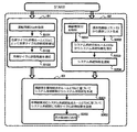
- FIG. 3 is a flowchart showing processing of the air-conditioning system diagnostic apparatus 100 according to Embodiment 1 of the present invention. Hereinafter, the operation of the air-conditioning system diagnosis apparatus 100 will be described with reference to FIG.
- the processing of the air conditioning system diagnostic apparatus 100 is roughly divided into the following steps S1 to S3.
- S1 System Diagnosis Step
- the operation information acquisition unit 120 acquires the operation information 31a from the air conditioner 10 via the network 20 and the communication unit 110.
- the refrigeration cycle analysis means 131 with which the system diagnosis means 130 is equipped performs the diagnosis of the refrigeration cycle in an air conditioning system based on the operation information 31a, and derives the refrigeration cycle diagnosis result which shows the presence or absence of a malfunction etc.
- S2 System System Analysis Step The device type recognition unit 140 acquires the device type 32 from the air conditioner 10 or the like via the network 20 and the communication unit 110.
- the communication list generating unit 150 acquires the communication destination device list 33 from the air conditioner 10 or the like via the network 20 and the communication unit 110, and generates a communication list based on the communication destination device list 33.
- the diagnosis result system diagram superimposing unit 170 generates a system system diagram based on the system system information derived by the system system analysis unit 160 and derives it by the refrigeration cycle analysis unit 131. The content of the refrigeration cycle diagnosis result is superimposed on the vicinity of the icon of the related device in the system system diagram, and the system system diagram on which the content of the refrigeration cycle diagnosis result is superimposed is output to the display 180.
- step S1 (Outline of operation of system diagnosis step S1) The details of the operation in step S1 will be described below with reference to FIG.
- the operation information generation means 31 in the outdoor unit 10a or the indoor unit 10b constituting the air conditioner 10 generates operation information 31a at regular intervals, and sends this operation information 31a to the network 20 via the communication means 30. Then, the operation information acquisition unit 120 in the air conditioning system diagnosis apparatus 100 acquires the operation information 31a via the communication unit 110 and notifies the system diagnosis unit 130 thereof.
- the transmission interval of the driving information 31a generated by the driving information generating means 31 to the network 20 is, for example, 30 seconds.
- the operation information 31a may be accumulated by the outdoor unit 10a or the indoor unit 10b at regular intervals, and the accumulated operation information 31a may be collected and transmitted to the operation information acquisition unit 120.
- the unit 10a or the indoor unit 10b may hold only the instantaneous operation information 31a, and the operation information acquisition unit 120 may acquire and store the operation information 31a at regular intervals.
- the driving information generating unit 31 is configured to send the driving information 31a to the network 20 at regular time intervals.
- the present invention is not limited to this, and the driving information acquiring unit 120 is configured to operate at regular time intervals.
- the operation information generation unit 31 may be configured to transmit a transmission command signal of the operation information 31a, transmit the operation information 31a to the network 20, and acquire the operation information 31a.
- the refrigeration cycle analysis means 131 in the system diagnosis means 130 sequentially detects the refrigerant temperature abnormality with respect to the state of the refrigeration cycle in the air conditioner 10 based on the refrigeration cycle analysis rule 131a from the operation information 31a notified by the operation information acquisition means 120. Then, a refrigeration cycle diagnosis result including information on the presence or absence of malfunctions such as abnormal refrigerant pressure, excessive or insufficient refrigerant quantity, or malfunction of the refrigerant control valve is derived.
- the refrigeration cycle analysis rule 131a is a rule for determining a malfunction of the refrigeration cycle that establishes the refrigerant system in the air conditioning system.
- the refrigeration cycle analysis rule 131a has an abnormal threshold value, and the refrigerant temperature value or the refrigerant pressure value exceeds the abnormal threshold value,
- the cycle diagnosis result may be determined as “abnormal”.
- the air conditioning system diagnostic device 100 stores prior operation information storage means for storing operation information (hereinafter referred to as prior operation information) at the time of past inspection of a specific refrigeration cycle in the air conditioning system to be diagnosed (
- prior operation information operation information
- the refrigeration cycle analysis means 131 compares the operation information 31a with the preliminary operation information, and the increase / decrease pattern of the refrigerant temperature value or the refrigerant pressure value is the refrigerant that the refrigeration cycle analysis rule 131a has.
- the refrigeration cycle diagnosis result may be determined as “abnormal” when the increase / decrease pattern is the same as or similar to the decrease / decrease pattern.
- the system diagnosis unit 130 notifies the diagnosis result superimposed diagram generation unit 170 of the refrigeration cycle diagnosis result derived by the refrigeration cycle analysis unit 131.
- step S2 (Outline of operation of system system analysis step S2) Hereinafter, the details of the operation in step S2 will be described with reference to FIG.
- the device type recognition unit 140 acquires the device type 32 held by the outdoor unit 10a, the indoor unit 10b, the refrigerant distribution device (not shown), the remote controller (not shown), or the like via the communication unit 110, The system system analysis means 160 is notified.
- the equipment type 32 is information representing a role in the air conditioning system such as the outdoor unit 10a, the indoor unit 10b, the refrigerant diversion device, and the remote controller.
- the communication list generation unit 150 acquires the communication destination device list 33 held by the outdoor unit 10a, the indoor unit 10b, the refrigerant distribution device (not shown), or the remote controller (not shown) via the communication unit 110.
- a communication list is generated based on the communication destination device list 33 and notified to the system system analysis means 160.
- the communication list is, for example, a list of combinations of transmission source devices and transmission destination devices.
- the system system analysis unit 160 connects the refrigerant type piping from the same outdoor unit 10a from the device type 32 acquired from the device type recognition unit 140 and the communication list acquired from the communication list generation unit 150.
- System system information including a refrigerant system representing the indoor unit 10b and the like, and an interlocking relationship representing the indoor unit 10b and the like operating in conjunction with the remote control operation is derived.
- the system system analysis rule 160a is a rule for determining the relationship between devices such as the outdoor unit 10a, the indoor unit 10b, the refrigerant flow dividing device, and the remote controller that constitute a certain air conditioning system.
- the air conditioning system includes a plurality of outdoor units 10a and a plurality of indoor units 10b
- the combination of the outdoor unit 10a and the indoor unit 10b is described in the communication list
- the combined outdoor unit 10a and the indoor unit It may be determined that the unit 10b belongs to the same refrigerant system, and when a plurality of combinations with different indoor units 10b for a certain remote controller are described in the communication list, the indoor units 10b May be determined to be linked.
- the system system analysis unit 160 notifies the derived system system information to the diagnosis result superimposed diagram generation unit 170.
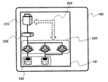
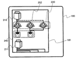
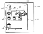
- FIG. 4 is a diagram showing a system system diagram in which main devices displayed on the display panel 181 of the air-conditioning system diagnosis apparatus 100 according to Embodiment 1 of the present invention are connected by lines, and FIG. It is the figure which highlighted the refrigerant system which connects between each apparatus displayed on the panel. The details of the operation in step S3 will be described below with reference to FIGS.
- the diagnosis result superimposed diagram generation means 170 generates a system system diagram composed of device icons and lines connecting them based on the inter-device main connection determination rule 170a from the system system information. For example, as shown in FIG. 4 representing the system diagram displayed on the display panel 181 of the display unit 180 in step S303 to be described later, it is represented by an icon that distinguishes the device type of each device constituting the air conditioning system.
- the diagnostic result superimposition diagram generating means 170 joins the main devices determined based on the inter-device main connection determination rule 170a from the devices having transmission / reception of control signals and the like with lines. Generate a system diagram.
- the outdoor unit 10a Based on the inter-apparatus main connection determination rule 170a, for example, when the outdoor unit 10a, the refrigerant diverter (not shown), the indoor unit 10b, and the remote controller (not shown) are connected to each other, the outdoor unit 10a
- the refrigerant branching device, the refrigerant branching device and the indoor unit 10b, and the indoor unit 10b and the remote controller are determined to be the main connection relationship, and the outdoor unit icon 210 indicating the outdoor unit 10a and the refrigerant indicating the refrigerant branching unit
- the flow dividing device icon 230, the refrigerant flow dividing device icon 230 and the indoor unit icon 220 indicating the indoor unit 10b, and the indoor unit icon 220 and the remote control icon 240 indicating the remote control are connected and connected.
- connection relationship between the outdoor unit 10a and the indoor unit 10b is determined as a non-main connection relationship, and the connection line 250 between the outdoor unit icon 210 and the indoor unit icon 220 is omitted.
- FIG. 4 shows an example of a system diagram, and the present invention is not limited to this.
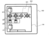
- the diagnostic result superimposition diagram generation means 170 displays the contents of the refrigeration cycle diagnosis result notified from the system diagnosis means 130 with respect to the generated system system diagram. It is superimposed on the vicinity of the device or device group related to the cycle diagnosis result. For example, when the refrigeration cycle diagnosis result includes detection information of a malfunction of the refrigeration cycle, the system system diagram displayed on the display panel 181 of the display unit 180 in step S303 described later is shown in FIG.
- information on the indoor unit 10b, the outdoor unit 10a, and their refrigerant system constituting the refrigeration cycle is extracted from the system system information, and the indoor unit icon 220 and the outdoor unit icon 210, which are icons corresponding to the respective devices, are extracted. And 211, and the connection lines 251 and 251a between them are emphasized and superposed, and those in which a malfunction has occurred, for example, the indoor unit 10b, the outdoor unit 10a in which the malfunction is detected, Strong about the indoor unit 10b, the outdoor unit 10a, and the refrigerant pipes connecting them with the same refrigerant pipe Generating a system diagram displaying by superimposing the those. For example, in FIG.
- FIG. 5 shows an example of a system diagram, and is not limited thereto.
- the diagnostic result superimposition diagram generating means 170 outputs the system system diagram generated from the system system information in step S301 and superimposing the contents of the refrigeration cycle diagnostic result in step S302 to the display 180.
- the display device 180 that has received the system system diagram causes the display panel 181 to display the system system diagram.
- the communication list generation unit 150 in the air conditioning system diagnosis device 100 includes By sequentially inquiring each of these devices and generating a communication list, system system information can be generated quickly and without omission, and the refrigeration cycle diagnosis result can be displayed. Further, by displaying only all devices and main connection relationships as a system system diagram as a system system diagram, the system system diagram is not complicated, and the device configuration of the air conditioning system can be easily recognized.
- the operation information acquisition means in the air conditioning system diagnostic device 100 is sequentially applied to each of these devices.
- the operation information 31a is obtained by inquiring, and the system diagnosis means 130 detects a problem related to the refrigeration cycle by performing an analysis of the refrigeration cycle based on the operation information 31a, and displays it as a refrigeration cycle diagnosis result. it can.
- the air conditioning system diagnostic apparatus 100 has preliminary operation information, by analyzing the refrigeration cycle using the acquired operation information 31a and the preliminary operation information, the air conditioning system such as refrigerant leakage can be analyzed.
- the communication list generating unit 150 acquires the communication destination device list 33 possessed by each device constituting the air conditioning system via the communication unit 110, and performs communication that summarizes them.
- the list is generated, but the present invention is not limited to this.
- the communication list may be generated based on the transmission source information and the transmission destination information acquired by the communication unit 110. Good. By such an operation, it is not necessary to perform communication for acquiring the communication destination device list 33 possessed by each device. Therefore, the communication list generating unit 150 does not load the network 20 and each device.
- a communication list can be generated, and the system system analysis means 160 can generate system system information even when the network 20 or each device is in a high load state.
- the apparatus classification recognition means 140 acquired the apparatus classification 32 which each apparatus which comprises an air conditioning system acquires via the communication means 110, it is restricted to this.
- the device type recognition unit 140 may acquire the communication list from the communication list generation unit 150 and estimate the device type 32 based on the combination of the communication list and the frequency of each communication indicated in the communication list. Good. For example, in a device group in which one-to-many communication is performed, it is estimated that the “1” side is the outdoor unit 10a and the “many” side is the indoor unit 10b, and the one-to-one communication with the indoor unit 10b is performed. It is presumed that the frequently implemented device is a remote control.
- the device type recognizing unit 140 does not impose a load on the network 20 and each device. 32, the system system analysis means 160 can generate system system information even if the network 20 or each device is in a high load state.
- the apparatus classification recognition means 140 acquired the apparatus classification 32 which each apparatus which comprises an air conditioning system acquires via the communication means 110, it is restricted to this. Instead, the device type recognition unit 140 acquires the communication list from the communication list generation unit 150, and estimates the device type 32 from the communication list and the content of the communication message acquired from the network 20 via the communication unit 110. Also good. For example, it is estimated that the transmission source of the operation stop command communication is a remote controller, the transmission destination is an indoor unit, and the destination to which the operation mode switching command communication is transmitted from the indoor unit is an outdoor unit. By such an operation, it is not necessary to perform communication for acquiring the device type 32 possessed by each device. Therefore, the device type recognizing unit 140 does not impose a load on the network 20 and each device. 32, the system system analysis means 160 can generate system system information even if the network 20 or each device is in a high load state.
- the operation information acquisition unit 120 acquires the operation information 31a of each device via the communication unit 110
- the device type recognition unit 140 acquires the device type 32 of each device via the communication unit 110
- the communication list generation unit 150 acquires the communication destination device list 33 of each device via the communication unit 110.
- the operation is not limited to this, and for example, the following operation may be performed.
- the air conditioning system diagnosis apparatus 100 includes a storage device, and stores in advance the operation information 31a, the device type 32, and the communication destination device list 33 from each device via the communication unit 110. deep.
- the operation information acquisition unit 120 stores the operation information 31a of each device
- the device type recognition unit 140 stores the device type 32 of each device
- the communication list generation unit 150 stores the communication destination device list 33 of each device.
- the air conditioning system diagnosis apparatus 100 can be diagnosed even when it is not connected to the air conditioning system to be diagnosed.
- the diagnosis result superimposition diagram generation means 170 outputs a system diagram in which the contents of the refrigeration cycle diagnosis results derived by the refrigeration cycle analysis means 131 by the system diagnosis means 130 are superimposed on the display 180.
- the air conditioning system diagnostic apparatus 100 includes a storage device, and the refrigeration cycle diagnosis result derived by the refrigeration cycle analysis means 131 by the system diagnosis unit 130 is stored in advance in the storage device.
- the diagnostic result superimposition diagram generating means 170 acquires the refrigeration cycle diagnostic result from the storage device, and outputs a system diagram on which the refrigeration cycle diagnostic result is superimposed to the display 180.
- the storage unit is configured to acquire and store in advance the refrigeration cycle diagnosis result derived by the refrigeration cycle analysis unit 131 by the system diagnosis unit 130.
- the storage unit stores the refrigeration cycle diagnosis result in advance by another method. It is good also as a structure which is memorize
- the diagnosis result superimposition diagram generation means 170 is configured to output the system system diagram generated from the system system information derived by the system system analysis means 160 to the display 180, but this is not limitative.
- the air conditioning system diagnosis apparatus 100 includes a storage device, and stores the system system information derived by the system system analysis unit 160 in advance in the storage device.
- the diagnostic result superimposition diagram generation means 170 acquires system system information from the storage device, generates a system system diagram, and outputs the system system diagram on which the contents of the refrigeration cycle diagnosis results are superimposed to the display 180.
- the storage means is configured to acquire and store the system system information derived by the system system analysis means 160 in advance.
- system system information is stored in the storage device in advance by another method.
- a configuration without 160 is also possible. Since the system system information is stored in advance in the storage device as described above, a system system diagram is quickly generated for the air conditioning system, and the refrigeration cycle diagnosis result is associated with the configuration of the air conditioning system. Can be displayed.
- FIG. 7 is a diagram showing an internal block of the air conditioning system diagnostic apparatus 100 according to Embodiment 2 of the present invention and the overall configuration of the air conditioning system.
- the difference from the air-conditioning system diagnosis apparatus 100 according to Embodiment 1 will be mainly described with reference to FIG.
- the air-conditioning system diagnosis apparatus 100 is configured by at least the component groups (1) to (4) as in the first embodiment, but (2) the state of the air-conditioning system.
- the component group for diagnosing is different from the first embodiment in the following points.
- the component group according to (2) in the first embodiment includes an operation information acquisition unit 120 and a system diagnosis unit 130, and the system diagnosis unit 130 is a refrigeration cycle. Although it was set as the structure provided with the analysis means 131, the component group which concerns on (2) in this Embodiment has the communication message
- the system diagnosis unit 130 includes a communication message analysis unit 132 that diagnoses the communication state of each device based on the communication message and derives a network diagnosis result described later.
- the communication message analysis unit 132 has a communication message analysis rule 132a for deriving the network diagnosis result.
- the communication message analysis rule 132a may be realized by a logic configured on software, or may be realized by a circuit device or the like equivalent thereto.
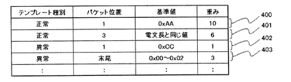
- FIG. 8 is a diagram illustrating an example of a normal template and an abnormal template for deriving a similarity with a communication message.
- the details of the operation in step S1 will be described with reference to FIGS. 3, 7, and 8.
- the communication message acquisition means 121 in the air conditioning system diagnosis apparatus 100 is connected to each of the outdoor unit 10a, the indoor unit 10b, the refrigerant distribution device (not shown), the remote controller (not shown), etc. via the communication means 110 from the network 20.
- a communication telegram including transmission source information and transmission destination information in communication performed between devices is acquired and notified to the system diagnosis unit 130.
- the communication message analysis unit 132 in the system diagnosis unit 130 is a network including information on the presence / absence of a network failure such as an illegal packet length from the communication message notified by the communication message acquisition unit 121 sequentially based on the communication message analysis rule 132a. Derive diagnostic results.
- the communication message analysis rule 132a is a determination of matching between a certain communication message format and a message format defined by a communication protocol used for communication between devices, or a comparison with a specific template. This is a rule for making a determination based on the degree of similarity. For example, when the communication message has a configuration different from the message format, the network diagnosis result is determined as “abnormal”.
- the communication message analysis rule 132a has a normal template and an abnormal template for a communication message, and the similarity between the normal template and the abnormal template and the acquired communication message is derived, and the similarity to the abnormality template is When it is high, the network diagnosis result may be determined as “abnormal”.
- This similarity is derived, for example, by the following method.
- the communication message analysis rule 132a has normal templates 400 and 401 and abnormal templates 402 and 403 as shown in FIG. 8 as the normal template.
- Each template is a template type that indicates whether it is a normal template or an abnormal template, a packet position that indicates the position of a packet in a communication message to be determined, a reference value that is a criterion for determination, and a case that corresponds to a determination Consists of weights to be added.
- the communication message analysis unit 132 extracts a packet corresponding to the packet position of each template from the packet group included in the acquired communication message, and the value is the same as the reference value of each template. Or whether it is included in the range indicated by the reference value, equal to or greater than the reference value, or equal to or less than the reference value.
- the weight value is added as the similarity related to the normal template.
- the template type is an abnormal template
- the weight value is added as the similarity related to the abnormal template.
- Each template shown above is merely an example, and the configuration of each template and the method for deriving the similarity based on each template are not limited to those shown above.
- the system diagnosis unit 130 notifies the diagnosis result superimposed diagram generation unit 170 of the network diagnosis result derived by the communication message analysis unit 132.
- FIG. 9 is a system diagram showing lines that connect control signals that are displayed on the display panel 181 of the air-conditioning system diagnosis apparatus 100 according to Embodiment 2 of the present invention and that have control signals transmitted and received.
- FIG. 9 the details of the operation in step S3 will be described with reference to FIGS. 3, 7, and 9.
- FIG. 9 is a system diagram showing lines that connect control signals that are displayed on the display panel 181 of the air-conditioning system diagnosis apparatus 100 according to Embodiment 2 of the present invention and that have control signals transmitted and received.
- the diagnosis result superimposed diagram generation means 170 generates a system system diagram composed of device icons and lines connecting them based on the inter-device main connection determination rule 170a from the system system information. For example, as shown in FIG. 9 showing a system system diagram displayed on the display panel 181 of the display unit 180 in step S303 to be described later, it is represented by an icon that distinguishes the device type of each device constituting the air conditioning system.
- the diagnostic result superimposition diagram generation means 170 creates a communication list obtained from each device that transmits and receives control signals and the like based on the inter-device main connection determination rule 170a, that is, from the system system information. A system diagram is created by connecting all the devices with lines.
- the outdoor unit 10a, the indoor unit 10b, and a remote controller (not shown) are connected to each other, the outdoor unit 10a, the indoor unit 10b, and the indoor unit 10b and the remote controller, it is determined that there is transmission / reception of a control signal or the like, and the outdoor unit icon 210 indicating the outdoor unit 10a, the indoor unit icon 220 indicating the indoor unit 10b, and the indoor unit icon 220 and the remote controller are indicated.
- Remote control icon 240 is shown connected by a connection line.
- the diagnostic result superimposition diagram generation means 170 displays the contents of the network diagnosis result notified from the system diagnosis means 130 with respect to the generated system system diagram. It superimposes in the vicinity of the apparatus or apparatus group related to a result, or those coupling lines.
- the network diagnosis result includes detection information of the malfunction of the communication state of each device
- FIG. 9 shows a system system diagram displayed on the display panel 181 of the display unit 180 in step S303 described later.
- a system system diagram is generated by highlighting and displaying the connection lines in the part where the malfunction occurs in the communication state of each device.
- FIG. 9 shows an example of a system diagram, and the present invention is not limited to this.
- the diagnostic result superimposition diagram generating means 170 generates the system system diagram generated from the system system information in step S301 and superimposing the contents of the network diagnosis result in step S302 to the display 180.
- the display device 180 that has received the system system diagram causes the display panel 181 to display the system system diagram.
- the communication result on the network of the air conditioning system is acquired, the communication message is analyzed, and the communication result is diagnosed to display the diagnosis result. it can.
- a network failure in the system diagram can be obtained by generating and displaying a diagram in which all communication between devices can be visually recognized as a system diagram. The location can be specifically visually confirmed.
- the communication message acquisition unit 121 acquires the communication message via the communication unit 110
- the device type recognition unit 140 acquires the device type 32 of each device via the communication unit 110
- the communication list generation unit 150 acquires the communication destination device list 33 of each device via the communication unit 110.
- the operation is not limited to this, and for example, the following operation may be performed.
- the air conditioning system diagnosis apparatus 100 includes a storage device, and stores a communication message, a device type 32, and a communication destination device list 33 from each device via the communication unit 110 in advance.
- the communication message acquisition unit 121 acquires a communication message
- the device type recognition unit 140 acquires the device type 32 of each device
- the communication list generation unit 150 acquires the communication destination device list 33 of each device from this storage device.
- the communication message 110, the device type 32, and the communication destination device list 33 are acquired directly via the communication unit 110 and stored in the storage device.
- the device type 32 and the communication destination device list 33 may be stored in the storage device, and the air conditioning system diagnosis device 100 may be configured not to include the communication unit 110.
- the information stored in the storage device may be any part of the communication message, the device type 32, and the communication destination device list 33.
- the storage device is configured to store the communication destination device list 33, the storage device is not limited to this, and the communication list is stored instead of the communication destination device list 33. It is good also as a structure which acquires a communication list. With the above operation, the air conditioning system diagnosis apparatus 100 can be diagnosed even when it is not connected to the air conditioning system to be diagnosed.
- the diagnostic result superimposition diagram generating means 170 outputs a system system diagram in which the contents of the network diagnostic result derived by the communication diagnostic analysis means 132 by the system diagnostic means 130 are superimposed on the display 180.
- movement it was set as operation
- the air conditioning system diagnosis apparatus 100 includes a storage device, and stores in advance the network diagnosis result derived by the system diagnosis unit 130 by the communication message analysis unit 132. Then, the diagnostic result superimposed diagram generation unit 170 acquires the network diagnostic result from the storage device, and outputs a system system diagram on which the network diagnostic result is superimposed to the display 180.
- the storage unit is configured to acquire and store in advance the network diagnosis result derived by the communication message analyzing unit 132 by the system diagnosis unit 130. However, the storage unit stores the network diagnosis result in advance in another storage method.
- the system diagnosis unit 130 may not be provided. As described above, since the network diagnosis result is stored in the storage device in advance, the network diagnosis result can be quickly displayed on the air conditioning system in association with the configuration of the air conditioning system.
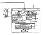
- FIG. 10 is a diagram showing an internal block of the air conditioning system diagnostic apparatus 100 according to Embodiment 3 of the present invention and the overall configuration of the air conditioning system.
- the difference from the air-conditioning system diagnosis apparatus 100 according to Embodiment 1 will be mainly described with reference to FIG.
- the air-conditioning system diagnosis apparatus 100 is configured by at least the component groups (1) to (4) as in the first embodiment, but (2) the state of the air-conditioning system.
- the component group for diagnosing is different from the first embodiment in the following points.
- the component group according to (2) in the first embodiment includes an operation information acquisition unit 120 and a system diagnosis unit 130, and the system diagnosis unit 130 is a refrigeration cycle.
- the analysis unit 131 is included, the component group according to (2) in the present embodiment includes the communication waveform acquisition unit 122 that acquires the communication waveform from the network 20 via the communication unit 110.
- the system diagnosis unit 130 includes a communication waveform analysis unit 133 that diagnoses the communication state of each device based on the communication waveform and derives a network diagnosis result to be described later.
- the communication waveform analysis means 133 has a communication waveform analysis rule 133a for deriving the network diagnosis result.
- the communication waveform analysis rule 133a may be configured by a logic configured on software, or may be configured by a circuit device or the like equivalent thereto.
- step S1 has the following operation.
- step S1 (Outline of operation of system diagnosis step S1) The details of the operation in step S1 will be described below with reference to FIGS.
- the communication waveform acquisition means 122 in the air conditioning system diagnosis apparatus 100 is connected to each of the outdoor unit 10a, the indoor unit 10b, the refrigerant distribution device (not shown), the remote controller (not shown), etc. from the network 20 via the communication means 110.
- a communication waveform in communication performed between devices is acquired and notified to the system diagnosis unit 130.
- the communication waveform analysis unit 133 in the system diagnosis unit 130 is a network having a low signal level or a rising waveform rounded waveform based on the communication waveform analysis rule 133a sequentially from the communication waveform notified by the communication waveform acquisition unit 122.
- a network diagnosis result including information on the presence / absence of a defect is derived.
- the communication waveform analysis rule 133a is a rule for determining a match between a certain communication waveform and an appropriate waveform. For example, if the difference in shape characteristics between the appropriate waveform and the communication waveform, such as signal width or amplitude, exceeds a certain threshold, the network diagnosis result is determined as “abnormal”.
- the system diagnosis unit 130 notifies the diagnosis result superimposed diagram generation unit 170 of the network diagnosis result derived by the communication waveform analysis unit 133.
- a communication waveform such as a control signal in the air conditioning system is acquired, the communication waveform is analyzed, and a diagnosis of a communication state is diagnosed, so that the diagnosis result can be displayed.
- a network failure in the system diagram can be obtained by generating and displaying a diagram in which all communication between devices can be visually recognized as a system diagram. The location can be specifically visually confirmed.
- the communication waveform acquisition unit 122 acquires the communication waveform via the communication unit 110
- the device type recognition unit 140 acquires the device type 32 of each device via the communication unit 110
- the communication list generation unit 150 acquires the communication destination device list 33 of each device via the communication unit 110.
- the operation is not limited to this, and for example, the following operation may be performed.
- the air conditioning system diagnosis apparatus 100 includes a storage device, and stores a communication waveform, a device type 32, and a communication destination device list 33 from each device via the communication unit 110 in advance. .
- the communication waveform acquisition unit 122 acquires the communication waveform
- the device type recognition unit 140 acquires the device type 32 of each device
- the communication list generation unit 150 acquires the communication destination device list 33 of each device from this storage device.
- a communication waveform is beforehand carried out by another method.
- the device type 32 and the communication destination device list 33 may be stored in the storage device, and the air conditioning system diagnosis device 100 may be configured not to include the communication unit 110.
- the information stored in the storage device may be any one of the communication waveform, the device type 32, and the communication destination device list 33.
- the storage device is configured to store the communication destination device list 33, the storage device is not limited to this, and the communication list is stored instead of the communication destination device list 33. It is good also as a structure which acquires a communication list. With the above operation, the air conditioning system diagnosis apparatus 100 can be diagnosed even when it is not connected to the air conditioning system to be diagnosed.
- the diagnostic result superimposition diagram generating means 170 outputs a system system diagram on which the contents of the network diagnostic result derived by the system diagnostic means 130 by the communication waveform analyzing means 133 are superimposed on the display 180.
- movement it was set as operation
- the air conditioning system diagnosis apparatus 100 includes a storage device, and stores in advance the network diagnosis result derived by the communication waveform analysis means 133 by the system diagnosis means 130 in this storage apparatus. Then, the diagnostic result superimposed diagram generation unit 170 acquires the network diagnostic result from the storage device, and outputs a system system diagram on which the network diagnostic result is superimposed to the display 180.
- the storage means is configured to previously acquire and store the network diagnosis result derived by the system diagnosis means 130 by the communication waveform analysis means 133.
- the network diagnosis result is previously stored in the storage device by another method.
- the system diagnosis unit 130 may not be provided. As described above, since the network diagnosis result is stored in the storage device in advance, the network diagnosis result can be quickly displayed on the air conditioning system in association with the configuration of the air conditioning system.
- FIG. FIG. 11 is a diagram showing an internal configuration of an air conditioning system diagnostic apparatus 100 according to Embodiment 4 of the present invention and the overall configuration of the air conditioning system.
- the difference from the air-conditioning system diagnosis apparatus 100 according to Embodiment 1 will be mainly described with reference to FIG.
- the air-conditioning system diagnosis apparatus 100 is configured by at least the component groups (1) to (4) as in the first embodiment, but (2) the state of the air-conditioning system. And (3) the component group for analyzing the system system of the air conditioning system differ from the first embodiment in the following points.
- the component group according to (2) in the first embodiment includes an operation information acquisition unit 120 and a system diagnosis unit 130, and the system diagnosis unit 130 is a refrigeration cycle.
- the analysis unit 131 is provided, the component group according to (2) in the present embodiment is configured only by the system diagnosis unit 130.
- the system diagnosis unit 130 includes a system configuration analysis unit 134 that derives a system configuration diagnosis result to be described later based on system information to be described later and the prior system system information 190a.
- the system configuration analysis means 134 has a system configuration analysis rule 134a for deriving the system configuration diagnosis result.
- the component group according to (3) in the present embodiment includes the prior system system information in addition to the component group according to (3) in the first embodiment.
- Pre-system system storage means 190 that stores 190a is included.
- system configuration analysis rule 134a may be configured by a logic configured on software, or may be configured by a circuit device or the like equivalent thereto.
- the prior system system storage unit 190 in the air conditioning system diagnostic apparatus 100 stores system system information (hereinafter referred to as prior system system information 190a) at the past inspection or design stage of the air conditioning system that is the diagnosis target.
- the system configuration analysis unit 134 in the system diagnosis unit 130 sequentially compares the system system information derived by the system system analysis unit 160 in step S204 described later and the prior system system information 190a stored in the prior system system storage unit 190. Based on the system configuration analysis rule 134a, a system configuration diagnosis result including information on presence / absence of a system configuration failure such as unexpected device detection and assumed device non-detection is derived.
- the system configuration analysis rule 134a is a rule for determining whether the system system information derived by the system system analysis unit 160 matches the pre-system system information 190a stored in the pre-system system storage unit 190. For example, when the device existing in the advance system system information 190a does not exist in the system system information, or when the device not present in the advance system system information 190a exists in the system system information, the system configuration diagnosis result is “abnormal”. judge. Further, for example, when the connection relationship between the devices indicated by the prior system system information 190a is different from the connection relationship between the devices indicated by the system system information, the system configuration diagnosis result may be determined as “abnormal”. (S103) The system diagnosis unit 130 notifies the diagnosis result superimposed diagram generation unit 170 of the system configuration diagnosis result derived by the system configuration analysis unit 134.
- step S2 (Outline of operation of system system analysis step S2) Hereinafter, the details of the operation in step S2 will be described with reference to FIGS.
- the device type recognition unit 140 acquires the device type 32 held by the outdoor unit 10a, the indoor unit 10b, the refrigerant distribution device (not shown), the remote controller (not shown), or the like via the communication unit 110, The system system analysis means 160 is notified.
- the equipment type 32 is information representing a role in the air conditioning system such as the outdoor unit 10a, the indoor unit 10b, the refrigerant diversion device, and the remote controller.
- the communication list generation unit 150 acquires the communication destination device list 33 held by the outdoor unit 10a, the indoor unit 10b, the refrigerant distribution device (not shown), or the remote controller (not shown) via the communication unit 110.
- a communication list is generated based on the communication destination device list 33 and notified to the system system analysis means 160.
- the communication list is, for example, a list of combinations of transmission source devices and transmission destination devices.
- the system system analysis unit 160 connects the refrigerant type piping from the same outdoor unit 10a from the device type 32 acquired from the device type recognition unit 140 and the communication list acquired from the communication list generation unit 150.
- System system information including a refrigerant system representing the indoor unit 10b and the like, and an interlocking relationship representing the indoor unit 10b and the like operating in conjunction with the remote control operation is derived.
- the system system analysis rule 160a is a rule for determining the relationship between devices such as the outdoor unit 10a, the indoor unit 10b, the refrigerant flow dividing device, and the remote controller that constitute a certain air conditioning system.
- the air conditioning system includes a plurality of outdoor units 10a and a plurality of indoor units 10b
- the combination of the outdoor unit 10a and the indoor unit 10b is described in the communication list
- the combined outdoor unit 10a and the indoor unit It may be determined that the unit 10b belongs to the same refrigerant system, and when a plurality of combinations with different indoor units 10b for a certain remote controller are described in the communication list, the indoor units 10b May be determined to be linked.
- the system system analysis unit 160 notifies the derived system system information to the diagnosis result superimposed diagram generation unit 170 and the system diagnosis unit 130.
- FIG. 12 is a diagram showing a system diagram that is displayed on the display panel 181 of the air-conditioning system diagnosis apparatus 100 according to Embodiment 4 of the present invention and that distinguishes between the past system configuration and the current system configuration. .
- the details of the operation in step S3 will be described with reference to FIGS. 3, 11, and 12.
- FIG. 12 is a diagram showing a system diagram that is displayed on the display panel 181 of the air-conditioning system diagnosis apparatus 100 according to Embodiment 4 of the present invention and that distinguishes between the past system configuration and the current system configuration.
- the diagnosis result superimposed diagram generation means 170 generates a system system diagram composed of device icons and lines connecting them based on the inter-device main connection determination rule 170a from the system system information. For example, as shown in FIG. 12 showing a system system diagram displayed on the display panel 181 of the display unit 180 in step S303 to be described later, it is represented by an icon that distinguishes the device type of each device constituting the air conditioning system.
- the diagnosis result superimposition diagram generating means 170 first generates a system diagram showing the current system configuration by connecting the devices determined based on the system main connection determination rule 170a from the system system information with lines.
- the outdoor unit 10a, the indoor unit 10b, and a remote controller are connected to each other, the outdoor unit 10a, the indoor unit 10b, and the indoor unit 10b and the remote controller are determined to be main connection relations, the outdoor unit icon 210 indicating the outdoor unit 10a, the indoor unit icon 220 indicating the indoor unit 10b, and the remote controller icon indicating the indoor unit icon 220 and the remote controller 240 is shown connected by a connecting line.
- the diagnosis result superimposition diagram generation means 170 is notified from the system diagnosis means 130 based on the diagnosis result corresponding system system diagram generation rule 170b to the system system diagram showing the current system configuration generated from the system system information.
- the past system configuration extracted from the system configuration diagnosis result is superimposed. For example, as shown in FIG. 12, for a device detected in both the system system information and the system configuration diagnosis result including the contents of the prior system system information 190a, a normal icon indicating the type of the device is used. Show. In FIG. 12, the outdoor unit icons 210 and 211, the indoor unit icon 220, and the remote control icon 240 correspond.
- the icon indicating the type of the device is indicated by a lighter icon.
- the prior system system information equipment icon 221 corresponds.
- an icon indicating the type of the device is flashed.
- the system system information device icon 222 corresponds.
- the past system configuration is compared with the current system configuration, A device that is determined to be abnormal in the system configuration, such as a device that is not assumed to be connected, or a device that is not assumed to be connected, or a device that has been determined to be normal in the system configuration. Or it is good also as what displays separately from the connection line.
- FIG. 12 shows an example of a system diagram, and is not limited thereto.
- the diagnostic result superimposition diagram generating means 170 generates the system system diagram generated from the system system information in step S301 and superimposing the contents of the system configuration diagnosis result in step S302 to the display 180.
- the display device 180 that has received the system system diagram causes the display panel 181 to display the system system diagram.
- the diagnostic result superimposition diagram generation means 170 outputs a system system diagram on which the contents of the system configuration diagnosis result derived by the system diagnostic means 130 by the system configuration analysis means 134 are superimposed on the display 180.
- the air conditioning system diagnosis apparatus 100 includes a storage device, and stores in advance the system configuration diagnosis result derived by the system diagnosis unit 130 by the system configuration analysis unit 134 in advance.
- the diagnosis result superimposition diagram generation means 170 acquires the system configuration diagnosis result from the storage device, and outputs a system system diagram on which the system configuration diagnosis result is superimposed to the display 180.
- the storage means is configured to previously acquire and store the system configuration diagnosis result derived by the system diagnosis means 130 by the system configuration analysis means 134. However, the storage means stores the system configuration diagnosis result in advance by another method. It is good also as a structure which is memorize
- FIG. FIG. 13 is a diagram showing an overall configuration of an internal block and an air conditioning system of an air conditioning system diagnostic apparatus 100 according to Embodiment 5 of the present invention.
- the difference from the air-conditioning system diagnosis apparatus 100 according to Embodiment 1 will be mainly described with reference to FIG.
- the air-conditioning system diagnosis apparatus 100 is configured by at least the component groups (1) to (4) as in the first embodiment, but (2) the state of the air-conditioning system.
- the component group for diagnosing is different from the first embodiment in the following points.
- the component group according to (2) in the first embodiment includes an operation information acquisition unit 120 and a system diagnosis unit 130, and the system diagnosis unit 130 is a refrigeration cycle.
- the analysis unit 131 is provided, the component group according to (2) in the present embodiment is configured only by the system diagnosis unit 130.
- the system diagnosis unit 130 includes a device setting analysis unit 135 for deriving a device setting diagnosis result described later based on a communication list described later.
- the device setting analysis unit 135 has a device setting analysis rule 135a for deriving the device setting diagnosis result.
- the device setting analysis rule 135a may be realized by a logic configured on software, or may be realized by a circuit device equivalent to this.
- the processing of the air conditioning system diagnostic apparatus 100 is roughly divided into the following steps S1 to S3.
- S1 System Diagnosis Step
- the device setting analysis unit 135 provided in the system diagnosis unit 130 performs detection of an unexpected device determined using a device ID described later based on a communication list described later, assumed device undetected, and the like. Including the device setting diagnosis result.
- S2 System System Analysis Step
- the device type recognition unit 140 acquires the device type 32 from the air conditioner 10 or the like via the network 20 and the communication unit 110.
- the communication list generating unit 150 acquires the communication destination device list 33 from the air conditioner 10 or the like via the network 20 and the communication unit 110, and generates a communication list based on the communication destination device list 33.
- the diagnosis result system diagram superimposing unit 170 generates a system system diagram based on the system system information derived by the system system analysis unit 160 and derives it by the device setting analysis unit 135. The content of the device setting diagnosis result is superimposed on the system system diagram, and the system system diagram on which the content of the device setting diagnosis result is superimposed is output to the display 180.
- step S1 (Outline of operation of system diagnosis step S1) The details of the operation in step S1 will be described below with reference to FIGS.
- the system diagnosis unit 130 in the air conditioning system diagnosis apparatus 100 acquires a communication list including a combination of device IDs described later from the communication list generation unit 150.
- the device setting analysis unit 135 in the system diagnosis unit 130 sequentially detects an unexpected device, an assumed device not detected, or a device ID from the communication list notified by the communication list generation unit 150 based on the device setting analysis rule 135a.
- a device setting diagnosis result including information on the presence / absence of a system configuration defect such as a double setting is derived.
- the device setting analysis rule 135a is a rule for determining the consistency of the combination of device IDs in the communication list. For example, when the device related to the combination of device IDs described in the communication list is not a device that can perform communication, the device setting diagnosis result is determined as “abnormal”.
- the device setting diagnosis result may be determined as “abnormal”.
- the system diagnosis unit 130 notifies the diagnosis result superimposed diagram generation unit 170 of the device setting diagnosis result derived by the device setting analysis unit 135.
- step S2 (Outline of operation of system system analysis step S2) Hereinafter, the details of the operation in step S2 will be described with reference to FIGS.
- the device type recognition unit 140 acquires the device type 32 held by the outdoor unit 10a, the indoor unit 10b, the refrigerant distribution device (not shown), the remote controller (not shown), or the like via the communication unit 110, The system system analysis means 160 is notified.
- the equipment type 32 is information representing a role in the air conditioning system such as the outdoor unit 10a, the indoor unit 10b, the refrigerant diversion device, and the remote controller.
- the communication list generating unit 150 includes a communication destination device including a device ID held by the outdoor unit 10a, the indoor unit 10b, the refrigerant distribution device (not shown) or the remote controller (not shown) via the communication unit 110.
- the list 33 is acquired, a communication list is generated based on the communication destination device list 33, and notified to the system system analysis unit 160 and the system diagnosis unit 130.
- the communication list is, for example, a list of combinations of transmission source devices and transmission destination devices each having a device ID.
- the system system analysis unit 160 connects the refrigerant type piping from the same outdoor unit 10a from the device type 32 acquired from the device type recognition unit 140 and the communication list acquired from the communication list generation unit 150.
- System system information including a refrigerant system representing the indoor unit 10b and the like, and an interlocking relationship representing the indoor unit 10b and the like operating in conjunction with the remote control operation is derived.
- the system system analysis unit 160 notifies the derived system system information to the diagnosis result superimposed diagram generation unit 170.
- FIG. 14 is a diagram showing a system system diagram in which devices that are displayed on the display panel 181 of the air-conditioning system diagnosis apparatus 100 according to Embodiment 2 of the present invention and are assigned device IDs are connected by lines. is there.
- the details of the operation in step S3 will be described with reference to FIGS.
- the diagnosis result superimposed diagram generation means 170 generates a system system diagram composed of icons of devices to which device IDs are assigned and lines connecting them based on the inter-device main connection determination rule 170a from the system system information. .
- FIG. 14 representing the system diagram displayed on the display panel 181 of the display 180 in step S303 described later, each device constituting the air conditioning system is distinguished by the device type and ID display unit 260. Represented by an icon to indicate.
- the diagnostic result superimposition diagram generation means 170 connects, with lines, main devices determined based on the inter-device main connection determination rule 170a from devices that transmit and receive control signals and the like. Generate a system diagram.
- the outdoor unit 10a, the indoor unit 10b, and a remote controller (not shown) are connected to each other, the outdoor unit 10a, the indoor unit 10b, and the indoor unit 10b and the remote controller, it is determined that there is transmission / reception of a control signal or the like, and the outdoor unit icon 210 indicating the outdoor unit 10a, the indoor unit icon 220 indicating the indoor unit 10b, and the indoor unit icon 220 and the remote controller are indicated.
- Remote control icon 240 is shown connected by a connection line.
- the outdoor unit icon 210, the indoor unit icon 220, and the remote control icon 240 are each displayed with a device ID.
- strain diagram is good also as what arranges the icon of the apparatus to which apparatus ID was provided in order of apparatus ID.
- the diagnostic result superimposition diagram generation means 170 based on the diagnostic result corresponding system system diagram generation rule 170b, generates the device setting diagnosis result notified from the system diagnosis means 130 with respect to the generated system system diagram. It superimposes in the vicinity of the apparatus or apparatus group related to a result, or those coupling lines. For example, when a malfunction in the device ID setting is detected as the device setting diagnosis result, as shown in FIG. 14, the icon related to the missing device ID, that is, the missing ID icon 223 is indicated by a dotted frame. .
- FIG. 14 shows an example of a system diagram, and the present invention is not limited to this.
- the diagnostic result superimposition diagram generating means 170 outputs the system system diagram generated from the system system information in step S301 and superimposing the contents of the device setting diagnosis result in step S302 to the display 180.
- the display device 180 that has received the system system diagram causes the display panel 181 to display the system system diagram.
- the device setting analysis unit 135 analyzes the communication list composed of device ID combinations, thereby detecting a failure related to device ID setting and displaying the detection result. .
- a device system configuration diagram in which the device ID is assigned to each device and the devices are arranged is generated, so that the device ID setting such as missing device ID setting is generated. It is possible to visually recognize the defect.
- the diagnostic result superimposition diagram generating unit 170 outputs a system system diagram in which the contents of the device setting diagnosis result derived by the system diagnostic unit 130 by the device setting analyzing unit 135 are superimposed on the display 180.
- the air conditioning system diagnostic apparatus 100 includes a storage device, and stores in advance the device setting diagnosis result derived by the device setting analysis unit 135 by the system diagnosis unit 130 in this storage device.
- the diagnostic result superimposition diagram generation means 170 acquires the device setting diagnosis result from the storage device, and outputs a system system diagram on which the device setting diagnosis result is superimposed to the display 180.
- the storage unit is configured to previously acquire and store the device setting diagnosis result derived by the device setting analysis unit 135 by the system diagnosis unit 130. However, the storage unit stores the device setting diagnosis result in advance by another method. It is good also as a structure which is memorize
- Embodiment 6 (Configuration of Air Conditioning System Diagnosis Device 100)
- the diagnosis result superimposed diagram generation means 170 may generate a system diagram that displays all detected defects in a superimposed manner.
- a description will be given focusing on differences from the air-conditioning system diagnosis apparatus 100 according to Embodiment 1.
- the air-conditioning system diagnosis apparatus 100 includes the communication message acquisition unit 121 described in the second embodiment in addition to the operation information acquisition unit 120.
- the system diagnosis unit 130 includes the communication message analysis unit 132 described in the second embodiment and the system configuration analysis unit 134 described in the fourth embodiment.
- the air conditioning system diagnosis apparatus 100 includes the prior system system storage unit 190 described in the fourth embodiment.
- FIG. 15 is a diagram showing a system diagram that is displayed on the display panel 181 of the air-conditioning system diagnosis apparatus 100 according to Embodiment 6 of the present invention and that shows a plurality of types of defects superimposed.
- the refrigeration cycle analysis unit 131 derives the refrigeration cycle diagnosis result as described in the first embodiment
- the communication message analysis unit 132 derives the network diagnosis result as described in the second embodiment
- the configuration analysis unit 134 derives a system configuration diagnosis result as described in the fourth embodiment. As shown in FIG.
- the diagnosis result superimposing diagram generation means 170 uses the system system diagram when no malfunction is detected as the minimum drawing element, and the refrigeration cycle diagnosis result, network diagnosis result, and system configuration diagnosis result When a defect is detected in any of the above, a system system diagram is generated by superimposing information indicating the defect as an additional drawing element.
- FIG. 15 shows an example of a system diagram, and the present invention is not limited to this.
- the system diagnosis unit 130 includes the refrigeration cycle analysis unit 131, the communication message analysis unit 132, and the system configuration analysis unit 134, but is not limited thereto. It is good also as a structure provided with the communication waveform acquisition means 122 demonstrated in Embodiment 3, the communication waveform analysis means 133, and the apparatus setting analysis means 135 demonstrated in Embodiment 5, The structure provided in any one of these It is good.
- the diagnostic result superimposition diagram generating means 170 is configured to generate a system system diagram that displays all of the plurality of types of defects detected by the system diagnostic means 130, but is not limited thereto. It is good also as operation
- FIG. FIG. 16 is a block diagram showing a configuration of an air-conditioning system diagnosis result display device 300 according to Embodiment 7 of the present invention.
- the air conditioning system diagnostic result display device 300 includes a system diagnostic result holding unit 310, a diagnostic result superimposed diagram generating unit 170, and a display 180.
- the display 180 includes a display panel 181 as shown in FIG.
- FIG. 17 is an example of a diagram showing a system diagram displayed on the display panel 181 of the air-conditioning system diagnosis result display apparatus 300 according to Embodiment 7 of the present invention.
- the system diagnosis result holding unit 310 holds the diagnosis result of the air conditioning system to be diagnosed, and notifies the diagnosis result superimposed diagram generation unit 170 of the diagnosis result.
- the diagnosis result refers to the refrigeration cycle diagnosis result derived by the refrigeration cycle analysis unit 131 described in the first embodiment, the communication message analysis unit 132 described in the second embodiment, and the communication waveform described in the third embodiment.
- the system diagnosis result holding unit 310 may acquire and hold the diagnosis result from the analysis unit.
- a diagnostic result it is not restricted to said thing, For example, when each apparatus which comprises an air conditioning system has a function which diagnoses a malfunction, it shall acquire it via a communication means.
- it may be provided with a storage device that stores the above-mentioned diagnosis results in advance, and may be obtained from the storage device, or provided with an input means that allows a user to input system installation information, etc. It is good also as what is acquired from.
- the diagnostic result superimposition diagram generating means 170 generates a system system diagram of the air conditioning system based on the diagnostic results held by the system diagnostic result holding means 310, and provides information related to the diagnostic results to the system system diagram. The information is superimposed and output to the display 180 so as to be emphasized.
- the display device 180 displays a system diagram on the display panel 181 on which the contents of the diagnosis result output from the diagnosis result superimposed diagram generating means 170 are superimposed.
- this system system diagram may be a diagram showing the position of each device in the building.
- the outdoor unit is a rooftop, and the indoor unit is in the building. It should be a diagram.
- an outdoor unit icon 210 indicating an outdoor unit is displayed on the roof portion of the building display unit 270 indicating a building
- an indoor unit icon 220 indicating an indoor unit and a remote control icon 240 indicating a remote control are displayed on each floor portion in the building. Is displayed. Note that FIG.
- FIG. 17 is a diagram illustrating an example of a system system diagram, and therefore, the layout of the display of the system system diagram is not limited.
- an icon indicating each device is displayed for each floor of a building according to a diagnosis result.
- a system system diagram suitable for the diagnosis result may be generated by changing the granularity of display such as for each room.
- the diagnosis result superimposition diagram generation means 170 generates the system system diagram as shown in FIG. 17, but is not limited to this.
- the air conditioning system widely emphasizes information related to the diagnosis results. For example, the connection line of each device in FIG. 17 may be removed, and a device layout diagram showing the layout of each device may be generated.
- an equipment operation abnormality analysis tool of a building equipment management system including air conditioning equipment and lighting equipment. Since the malfunction of the air conditioning system in the refrigeration cycle of the air conditioner and the network between each apparatus can be displayed in an easy-to-understand manner, for example, problems such as deterioration over time of the air conditioner can be detected and dealt with early.
Landscapes
- Engineering & Computer Science (AREA)
- General Engineering & Computer Science (AREA)
- Chemical & Material Sciences (AREA)
- Combustion & Propulsion (AREA)
- Mechanical Engineering (AREA)
- Physics & Mathematics (AREA)
- General Physics & Mathematics (AREA)
- Automation & Control Theory (AREA)
- Biomedical Technology (AREA)
- Health & Medical Sciences (AREA)
- Air Conditioning Control Device (AREA)
- Processing Or Creating Images (AREA)
- Computer And Data Communications (AREA)
Abstract
Description
また、このシステム系統図については、各室内機に接続している室外機又はリモコンに問い合わせることにより、自動で機器構成を取得してシステム系統図を生成する空気調和システムの集中管理装置が提案されている(例えば、特許文献2参照)。
(空気調和システム診断装置100の構成)
図1は、本発明の実施の形態1に係る空気調和システム診断装置100の内部ブロック及び空気調和システムの全体構成を示す図である。
図1で示されるように、少なくとも室外機10a、及び、1つ又は複数の室内機10bによって構成される空気調和機10が、ネットワーク20に複数接続されている。また、空気調和システムの不具合の診断を実施する空気調和システム診断装置100が、ネットワーク20に接続されている。
なお、図1においては、複数の空気調和機10がネットワーク20に接続される構成が示されているが、これに限られるものではなく、1つの空気調和機10が接続されるものとしてもよい。
(1)ネットワーク20を流れるデータを取得する構成要素群
(2)空気調和システムの状態を診断する構成要素群
(3)空気調和システムのシステム系統を分析する構成要素群
(4)(2)における診断結果及び(3)におけるシステム系統を合わせて表示する構成要素群
上記(1)~(4)の構成要素群は、さらに、下記に示す構成要素によって構成されている。
ネットワーク20に接続され、そのネットワーク20からデータを送受信する通信手段110によって構成される。
(2)に係る構成要素群は、空気調和機10を構成する室外機10a又は室内機10bが保有する運転情報31a(図2の説明において後述する)を、ネットワーク20及び通信手段110を介して取得する運転情報取得手段120を有する。さらに、(2)に係る構成要素群は、この運転情報取得手段120によって取得された運転情報31aに基づいて空気調和システムの状態を診断するシステム診断手段130を有する。
システム診断手段130は、取得した運転情報31aに基づいて空気調和システムにおける冷凍サイクルの状態の診断を実施して冷凍サイクル診断結果(図3の説明において後述する)を導出する冷凍サイクル解析手段131を備えている。この冷凍サイクル解析手段131は、上記の冷凍サイクル診断結果を導出するための冷凍サイクル解析ルール131aを保有している。
(3)に係る構成要素群は、空気調和機10を構成する室外機10a又は室内機10bが保有する機器種別32(図2の説明において後述する)を、ネットワーク20及び通信手段110を介して取得する機器種別認識手段140を有する。また、(3)に係る構成要素群は、空気調和機10を構成する室外機10a又は室内機10bが保有する通信先機器リスト33(図2の説明において後述する)を、ネットワーク20及び通信手段110を介して取得する通信リスト生成手段150を有する。さらに、(3)に係る構成要素群は、上記の機器種別認識手段140によって取得された機器種別32、及び、通信リスト生成手段150によって生成された通信リスト(図3の説明において後述する)に基づいて、空気調和システムの冷媒系統及び連動関係等を含むシステム系統情報(図3の説明において後述する)を導出するシステム系統分析手段160を有する。
システム系統分析手段160は、システム系統情報を導出するためのシステム系統分析ルール160aを保有している。
(4)に係る構成要素群は、システム系統分析手段160によって導出されたシステム系統情報に基づいて、室外機10a及び室内機10b等のアイコン並びにそれらを結ぶ線によって構成されるシステム系統図(図3の説明において後述する)を生成して、冷凍サイクル解析手段131によって導出された冷凍サイクル診断結果を、システム系統図において関連する機器のアイコン近傍に重畳する診断結果重畳図生成手段170を有する。さらに、(4)に係る構成要素群は、冷凍サイクル診断結果の内容が重畳されたシステム系統図を表示する表示器180を有する。
診断結果重畳図生成手段170は、システム系統図を生成するための機器間主要接続決定ルール170a及び診断結果対応システム系統図生成ルール170bを保有している。
図2で示されるように、室外機10a及び室内機10bは、ネットワーク20に接続され、そのネットワーク20からデータを送受信する通信手段30を備えている。また、室外機10a及び室内機10bは、冷媒温度値又は冷媒圧力値等の運転情報31aを生成する運転情報生成手段31を備えている。さらに、室外機10a及び室内機10bは、その機器種類又は機能等を示す機器種別32、及び、制御信号等の通信先のリストである通信先機器リスト33を保有している。
通信手段30は、運転情報生成手段31によって生成された運転情報31a、機器種別32及び通信先機器リスト33をネットワーク20に送出する。
また、図2で示される構成を備えるのは室外機10a及び室内機10bとしているが、これに限られるものではなく、室外機10a及び室内機10b以外の機器、例えば、空気調和システムを構成する冷媒回路を分流する冷媒分流装置、又は、リモコン等その他の機器が、図2で示される構成を備え、運転情報31a、機器種別32又は通信先機器リスト33をネットワーク20に送出する構成としてもよい。
また、運転情報取得手段120、システム診断手段130、機器種別認識手段140、通信リスト生成手段150、システム系統分析手段160、又は、診断結果重畳図生成手段170は、回路デバイスのようなハードウェアによって実現される構成としてもよく、又は、マイコン若しくはCPUのような演算装置によって実行されるソフトウェアとして実現される構成としてもよい。
さらに、冷凍サイクル解析ルール131a、システム系統分析ルール160a、機器間主要接続決定ルール170a、又は、診断結果対応システム系統図生成ルール170bは、ソフトウェア上に構成されたロジックによって実現される構成としてもよく、又は、これと等価な回路デバイス等によって実現される構成としてもよい。
図3は、本発明の実施の形態1に係る空気調和システム診断装置100の処理を示すフローチャートである。以下、図3を参照しながら、空気調和システム診断装置100の動作を説明する。
(S1)システム診断ステップ
運転情報取得手段120は、ネットワーク20及び通信手段110を介して、空気調和機10から運転情報31aを取得する。そして、システム診断手段130が備える冷凍サイクル解析手段131は、その運転情報31aに基づいて、空気調和システムにおける冷凍サイクルの診断を実施して不具合等の有無を示す冷凍サイクル診断結果を導出する。
(S2)システム系統分析ステップ
機器種別認識手段140は、ネットワーク20及び通信手段110を介して、空気調和機10等から機器種別32を取得する。また、通信リスト生成手段150は、ネットワーク20及び通信手段110を介して、空気調和機10等から通信先機器リスト33を取得し、この通信先機器リスト33に基づいて通信リストを生成する。そして、システム系統分析手段160は、機器種別32及び通信リストに基づいて、空気調和システムの冷媒系統及び連動関係等を含むシステム系統情報を導出する。
(S3)診断結果システム系統図重畳表示ステップ
診断結果重畳図生成手段170は、システム系統分析手段160によって導出されたシステム系統情報に基づいて、システム系統図を生成し、冷凍サイクル解析手段131によって導出された冷凍サイクル診断結果の内容を、システム系統図における関連する機器のアイコン近傍に重畳させて、その冷凍サイクル診断結果の内容が重畳されたシステム系統図を表示器180に出力する。
以下、図3を参照しながら、ステップS1の動作の詳細を説明する。
空気調和機10を構成する室外機10a又は室内機10bにおける運転情報生成手段31は、一定時間毎に運転情報31aを生成し、この運転情報31aを通信手段30を介してネットワーク20に送出する。そして、空気調和システム診断装置100における運転情報取得手段120は、通信手段110を介して、その運転情報31aを取得し、システム診断手段130に通知する。上記の、運転情報生成手段31によって生成される運転情報31aのネットワーク20への送出間隔は、例えば、30秒とする。
なお、運転情報31aは、一定時間毎に室外機10a又は室内機10bによって蓄積され、その蓄積された運転情報31aをまとめて、運転情報取得手段120に送信されるものとしてもよく、また、室外機10a又は室内機10bは、瞬間の運転情報31aのみを保持し、一定時間毎に運転情報取得手段120がその運転情報31aを取得し蓄積するものとしてもよい。
また、上記においては、運転情報生成手段31が、一定時間毎に運転情報31aをネットワーク20に送出する動作としたが、これに限られるものではなく、運転情報取得手段120が、一定時間毎に、運転情報生成手段31に対して運転情報31aの送出指令信号を送信して、運転情報31aをネットワーク20に送出させ、その運転情報31aを取得する動作としてもよい。
システム診断手段130における冷凍サイクル解析手段131は、運転情報取得手段120によって通知された運転情報31aから、逐次、冷凍サイクル解析ルール131aに基づいて、空気調和機10における冷凍サイクルの状態について冷媒温度異常、冷媒圧力異常、冷媒量過不足又は冷媒制御弁の故障等の不具合の有無の情報を含む冷凍サイクル診断結果を導出する。
ここで、冷凍サイクル解析ルール131aとは、空気調和システムにおける冷媒系統を成立させている冷凍サイクルの不具合を判定するためのルールである。例えば、運転情報31aが冷媒温度値又は冷媒圧力値等を含有し、冷凍サイクル解析ルール131aが異常閾値を有し、その冷媒温度値又は冷媒圧力値等がその異常閾値を超えた場合に、冷凍サイクル診断結果を「異常有り」と判定してもよい。また、例えば、空気調和システム診断装置100が、診断対象となる空気調和システムにおける特定の冷凍サイクルの過去の点検時等の運転情報(以下、事前運転情報という)を記憶する事前運転情報記憶手段(図示せず)を備える構成とし、冷凍サイクル解析手段131は、運転情報31aと事前運転情報とを比較し、冷媒温度値又は冷媒圧力値等の増減パターンが、冷凍サイクル解析ルール131aが有する冷媒が減少した場合の増減パターンと一致又は類似している場合に、冷凍サイクル診断結果を「異常有り」と判定しても良い。
システム診断手段130は、冷凍サイクル解析手段131が導出した冷凍サイクル診断結果を、診断結果重畳図生成手段170に通知する。
以下、図3を参照しながら、ステップS2の動作の詳細を説明する。
機器種別認識手段140は、通信手段110を介して、室外機10a、室内機10b、冷媒分流装置(図示せず)又はリモコン(図示せず)等が保有している機器種別32を取得し、システム系統分析手段160に通知する。
ここで、機器種別32とは、室外機10a、室内機10b、冷媒分流装置及びリモコン等の空気調和システムにおける役割を表す情報である。
通信リスト生成手段150は、通信手段110を介して、室外機10a、室内機10b、冷媒分流装置(図示せず)又はリモコン(図示せず)が保有している通信先機器リスト33を取得し、この通信先機器リスト33に基づいて通信リストを生成し、システム系統分析手段160に通知する。
ここで、通信リストとは、例えば、送信元機器と送信先機器との組み合わせをリストにしたものである。
システム系統分析手段160は、機器種別認識手段140から取得した機器種別32及び通信リスト生成手段150から取得した通信リストから、システム系統分析ルール160aに基づいて、同一の室外機10aから冷媒配管で接続される室内機10b等を表す冷媒系統、及び、リモコン操作時に連動して動作する室内機10b等を表す連動関係等を含むシステム系統情報を導出する。
ここで、システム系統分析ルール160aとは、ある空気調和システムを構成する室外機10a、室内機10b、冷媒分流装置及びリモコン等の機器間の関係を判定するためのルールである。例えば、空気調和システムに複数の室外機10aと複数の室内機10bがあり、通信リストに室外機10aと室内機10bとの組み合わせが記載されているときに、組み合わされている室外機10a及び室内機10bが同一の冷媒系統に属していると判定してもよいし、また、ある1つのリモコンについて異なる室内機10bとの組み合わせが通信リストに複数記載されているときに、それらの室内機10bは連動関係にあると判定してもよい。
システム系統分析手段160は、導出したシステム系統情報を、診断結果重畳図生成手段170に通知する。
図4は、本発明の実施の形態1に係る空気調和システム診断装置100の表示パネル181に表示される主要な機器間を線で結合したシステム系統図を示す図であり、図5は、表示パネル181に表示される各機器間を接続する冷媒系統を強調表示した図である。以下、図3~図5を参照しながら、ステップS3の動作の詳細を説明する。
診断結果重畳図生成手段170は、システム系統情報から、機器間主要接続決定ルール170aに基づいて、機器のアイコン及びそれらを結ぶ線等から構成されるシステム系統図を生成する。例えば、後述するステップS303において表示器180の表示パネル181に表示されるシステム系統図を表す図4で示されるように、空気調和システムを構成する各機器の機器種別を区別して示すアイコンで表される。診断結果重畳図生成手段170は、この図4で示されるように、制御信号等の送受信がある機器間から、機器間主要接続決定ルール170aに基づいて決定した主要な機器間を、線で結合したシステム系統図を生成する。この機器間主要接続決定ルール170aに基づいて、例えば、室外機10a、冷媒分流装置(図示せず)、室内機10b及びリモコン(図示せず)が相互に接続している場合に、室外機10a及び冷媒分流装置、冷媒分流装置及び室内機10b、並びに、室内機10b及びリモコンの接続関係を主要な接続関係であると決定し、室外機10aを示す室外機アイコン210及び冷媒分流装置を示す冷媒分流装置アイコン230、その冷媒分流装置アイコン230及び室内機10bを示す室内機アイコン220、並びに、その室内機アイコン220及びリモコンを示すリモコンアイコン240を接続線で結合して示す。一方、室外機10aと室内機10bとの接続関係を主要でない接続関係と決定し、室外機アイコン210と室内機アイコン220との接続線250を省略する。
なお、図4は、システム系統図の例を示すものであり、これによって限定されるものではない。
そして、診断結果重畳図生成手段170は、診断結果対応システム系統図生成ルール170bに基づいて、システム診断手段130から通知された冷凍サイクル診断結果の内容を、生成したシステム系統図に対してその冷凍サイクル診断結果に関連する機器又は機器群の付近に重畳する。例えば、冷凍サイクル診断結果に冷凍サイクルの不具合の検出情報が含まれている場合には、後述するステップS303において表示器180の表示パネル181に表示されるシステム系統図を表す図5で示されるように、システム系統情報から冷凍サイクルを構成する室内機10b、室外機10a、及びそれらの冷媒系統の情報を抽出し、それぞれの機器に対応するアイコンである室内機アイコン220、及び、室外機アイコン210及び211、並びに、それらの間の接続線251及び251aについて強調して重畳し、また、これらについて、不具合が発生しているもの、例えば、不具合が検出された室内機10b、室外機10aと、同一の冷媒配管で結合された室内機10b、室外機10a及びそれらを結合する冷媒配管について強調したものを重畳して表示したシステム系統図を生成する。
例えば、図5において、特定の室外機10aに冷媒不足が発生しているものとし、その室外機10aに該当する室外機アイコン210に冷媒不足表示部215を重畳して表示している。
なお、上記においては不具合が発生している接続線又は機器を強調して表示する動作としたが、これに限られるものではなく、対象とする空気調和システムに存在する全ての機器及び接続線について強調して表示する動作としてもよい。
また、図5は、システム系統図の例を示すものであり、これによって限定されるものではない。
さらに、診断結果重畳図生成手段170は、ステップS301においてシステム系統情報から生成し、ステップS302において冷凍サイクル診断結果の内容を重畳したシステム系統図を、表示器180に出力する。システム系統図を受信した表示器180は、表示パネル181にそのシステム系統図を表示させる。
以上のような構成及び動作によって、空気調和システムを表現するシステム系統図に冷凍サイクル診断結果を重畳して表示するため、冷凍サイクル診断結果と空気調和システムとの対応関係が容易に視認できる。そして、これによって速やかに不具合に対する対応をとることができ、不具合を早期に解決することができる。
また、室外機10a、室内機10b、冷媒分流装置及びリモコン等の各機器が機器種別32を保有している空気調和システムにおいて、空気調和システム診断装置100における機器種別認識手段140が、それらの各機器に順次問い合わせて機器種別を認識することで、漏れなくかつ迅速にシステム系統情報を生成し、冷凍サイクル診断結果の表示を行うことができる。
また、室外機10a、室内機10b、冷媒分流装置及びリモコン等の各機器が通信先機器リスト33を保有している空気調和システムにおいて、空気調和システム診断装置100における通信リスト生成手段150が、それらの各機器に順次問い合わせて通信リストの生成を行うことで、漏れなくかつ迅速にシステム系統情報を生成し、冷凍サイクル診断結果の表示を行うことができる。
また、システム系統図として、すべての機器及び主要な接続関係のみをシステム系統図として表示することで、システム系統図が煩雑でなくなり、空気調和システムの機器構成を容易に視認することができる。
また、室外機10a、室内機10b及び冷媒分流装置等の各機器が運転情報31aを保有している空気調和システムにおいて、空気調和システム診断装置100における運転情報取得手段が、それらの各機器に順次問い合わせて運転情報31aを取得し、システム診断手段130が、その運転情報31aに基づいて、冷凍サイクルの解析を実施することで、冷凍サイクルに関する不具合を検出し、冷凍サイクル診断結果として表示することができる。
また、空気調和システム診断装置100が、事前運転情報を保有している場合には、取得した運転情報31a及び事前運転情報を用いて冷凍サイクルの解析を行うことで、冷媒漏れといった空気調和システムの経年劣化による冷凍サイクルに関する不具合を検出し、冷凍サイクル診断結果として表示することができる。
さらに、冷凍サイクルの不具合が冷凍サイクル診断結果として得られた場合には、システム系統図として室外機10a、室内機10b又は冷媒分流装置等、並びに、それらの接続線を強調した図を生成することで、システム系統図における冷凍サイクルを構成する各機器及び接続関係と冷凍サイクル診断結果との関連を容易に視認できる。
(空気調和システム診断装置100の構成)
図7は、本発明の実施の形態2に係る空気調和システム診断装置100の内部ブロック及び空気調和システムの全体構成を示す図である。以下、図7を参照しながら、実施の形態1に係る空気調和システム診断装置100と相違する点を中心に説明する。
実施の形態1における(2)に係る構成要素群は、運転情報取得手段120及びシステム診断手段130から構成され、システム診断手段130は冷凍サイクル解析手段131を備える構成としていたが、本実施の形態における(2)に係る構成要素群は、ネットワーク20から通信手段110を介して通信電文を取得する通信電文取得手段121を有している。また、システム診断手段130は、その通信電文に基づいて各機器の通信状態の診断を実施して後述するネットワーク診断結果を導出する通信電文解析手段132を備えている。この通信電文解析手段132は、上記のネットワーク診断結果を導出するための通信電文解析ルール132aを保有している。
本実施の形態に係る空気調和システム診断装置100の処理は、ステップS2については、実施の形態1と同様であるが、ステップS1及びステップS3は下記のような動作となる。
図8は、通信電文との類似度を導出するための正常テンプレート及び異常テンプレートの例を示す図である。以下、図3、図7及び図8を参照しながら、ステップS1の動作の詳細を説明する。
空気調和システム診断装置100における通信電文取得手段121は、ネットワーク20から通信手段110を介して、室外機10a、室内機10b、冷媒分流装置(図示せず)及びリモコン(図示せず)等の各機器間で実施される通信における送信元情報及び送信先情報等を含む通信電文を取得し、システム診断手段130に通知する。
システム診断手段130における通信電文解析手段132は、通信電文取得手段121によって通知された通信電文から、逐次、通信電文解析ルール132aに基づいて、不正パケット長等のネットワーク不具合の有無の情報を含むネットワーク診断結果を導出する。
ここで、通信電文解析ルール132aとは、ある通信電文のフォーマットと、機器間の通信に用いられる通信プロトコルで規定されている電文フォーマットとの一致の判定、又は、特定のテンプレートとの比較をしてその類似度によって判定をするためのルールである。
例えば、その電文フォーマットと異なる構成の通信電文である場合に、ネットワーク診断結果を「異常あり」と判定する。
また、例えば、通信電文解析ルール132aが通信電文についての正常テンプレート及び異常テンプレートを有し、その正常テンプレート及び異常テンプレートと、取得した通信電文との類似度を導出し、異常テンプレートとの類似度が高いときにネットワーク診断結果を「異常あり」と判定してもよい。この類似度について、例えば、下記の方法によって導出する。通信電文解析ルール132aは、上記の正常テンプレートとして、図8で示されるような、正常テンプレート400及び401、並びに、異常テンプレート402及び403を有しているものとする。各テンプレートは、正常テンプレートであるか異常テンプレートであるかを示すテンプレート種別、判定対象となる通信電文におけるパケットの位置を示すパケット位置、判定の基準となる基準値、及び、判定に該当した場合に加算される重みによって構成される。このとき、通信電文解析手段132は、取得した通信電文に含有されるパケット群から、各テンプレートが有するパケット位置に該当するパケットを抽出し、その値が、各テンプレートが有する基準値と同一であるか、基準値で示される範囲に含まれるか、基準値以上であるか、又は、基準値以下であるか等の判定を実施する。そして、その判定条件を満たす場合で、かつ、そのテンプレートのテンプレート種別が正常テンプレートである場合は、正常テンプレートに係る類似度としてその重みの値を加算する。また、テンプレート種別が異常テンプレートである場合は、異常テンプレートに係る類似度としてその重みの値を加算する。そして、得られた正常テンプレートに係る類似度及び異常テンプレートに係る類似度に基づいて、通信電文について判定する。例えば、異常テンプレートに係る類似度が所定の閾値以上、又は、異常テンプレートに係る類似度が正常テンプレートに係る類似度よりも大きい等であれば、ネットワーク診断結果を「異常あり」と判定する。
なお、上記に示した各テンプレートはあくまで例示したものであり、各テンプレートの構成及び各テンプレートに基づく類似度の導出方法は、上記で示したものに限定されるものではない。
システム診断手段130は、通信電文解析手段132が導出したネットワーク診断結果を、診断結果重畳図生成手段170に通知する。
図9は、本発明の実施の形態2に係る空気調和システム診断装置100の表示パネル181に表示され、各機器において制御信号の送受信があるものを線で結合して示したシステム系統図を示す図である。以下、図3、図7及び図9を参照しながら、ステップS3の動作の詳細を説明する。
診断結果重畳図生成手段170は、システム系統情報から、機器間主要接続決定ルール170aに基づいて、機器のアイコン及びそれらを結ぶ線等から構成されるシステム系統図を生成する。例えば、後述するステップS303において表示器180の表示パネル181に表示されるシステム系統図を表す図9で示されるように、空気調和システムを構成する各機器の機器種別を区別して示すアイコンで表される。診断結果重畳図生成手段170は、この図9で示されるように、機器間主要接続決定ルール170aに基づいて制御信号等の送受信がある各機器間、すなわち、システム系統情報から求められる通信リストにあるすべての機器間を、線で結合したシステム系統図を生成する。この機器間主要接続決定ルール170aに基づいて、例えば、室外機10a、室内機10b及びリモコン(図示せず)が相互に接続している場合に、室外機10a及び室内機10b、並びに、室内機10b及びリモコンのそれぞれの間で制御信号等の送受信があると決定し、室外機10aを示す室外機アイコン210及び室内機10bを示す室内機アイコン220、並びに、その室内機アイコン220及びリモコンを示すリモコンアイコン240を接続線で結合して示す。
そして、診断結果重畳図生成手段170は、診断結果対応システム系統図生成ルール170bに基づいて、システム診断手段130から通知されたネットワーク診断結果の内容を、生成したシステム系統図に対してそのネットワーク診断結果に関連する機器若しくは機器群、又は、それらの結合線の付近に重畳する。例えば、ネットワーク診断結果に各機器の通信状態の不具合の検出情報が含まれている場合には、後述するステップS303において表示器180の表示パネル181に表示されるシステム系統図を表す図9で示されるように、各機器の通信状態に不具合が発生している部分の接続線について強調して表示したシステム系統図を生成する。図9においては、室外機10aと、室内機10bのうち1台との通信状態に不具合が発生しているものとし、その接続線をネットワーク異常線252として強調したものを重畳して表示している。
なお、図9は、システム系統図の例を示すものであり、これによって限定されるものではない。
さらに、診断結果重畳図生成手段170は、ステップS301においてシステム系統情報から生成し、ステップS302においてネットワーク診断結果の内容を重畳したシステム系統図を、表示器180に出力する。システム系統図を受信した表示器180は、表示パネル181にそのシステム系統図を表示させる。
以上のような構成及び動作のように、空気調和システムのネットワーク上の通信電文を取得してその通信電文の解析を実施し通信状態の不具合を診断することによって、その診断結果を表示することができる。
また、通信状態の不具合がネットワーク診断結果として得られた場合には、システム系統図として機器間通信をすべて個別に視認可能な図を生成して表示することによって、そのシステム系統図におけるネットワークの不具合箇所を具体的に視認することができる。
(空気調和システム診断装置100の構成)
図10は、本発明の実施の形態3に係る空気調和システム診断装置100の内部ブロック及び空気調和システムの全体構成を示す図である。以下、図10を参照しながら、実施の形態1に係る空気調和システム診断装置100と相違する点を中心に説明する。
実施の形態1における(2)に係る構成要素群は、運転情報取得手段120及びシステム診断手段130から構成され、システム診断手段130は冷凍サイクル解析手段131を備える構成としていたが、本実施の形態における(2)に係る構成要素群は、ネットワーク20から通信手段110を介して通信波形を取得する通信波形取得手段122を有している。また、システム診断手段130は、その通信波形に基づいて各機器の通信状態の診断を実施して後述するネットワーク診断結果を導出する通信波形解析手段133を備えている。この通信波形解析手段133は、上記のネットワーク診断結果を導出するための通信波形解析ルール133aを保有している。
本実施の形態に係る空気調和システム診断装置100の処理は、ステップS2及びステップS3については、実施の形態1と同様であるが、ステップS1は下記のような動作となる。
以下、図3及び図10を参照しながら、ステップS1の動作の詳細を説明する。
空気調和システム診断装置100における通信波形取得手段122は、ネットワーク20から通信手段110を介して、室外機10a、室内機10b、冷媒分流装置(図示せず)及びリモコン(図示せず)等の各機器間で実施される通信における通信波形を取得し、システム診断手段130に通知する。
システム診断手段130における通信波形解析手段133は、通信波形取得手段122によって通知された通信波形から、逐次、通信波形解析ルール133aに基づいて、信号レベルが低い、又は、波形の立ち上がりなまり等のネットワーク不具合の有無の情報を含むネットワーク診断結果を導出する。
ここで、通信波形解析ルール133aとは、ある通信波形と適正波形との一致を判定するためのルールである。例えば、適正波形と通信波形との形状特徴、例えば、信号幅又は振幅等の差が一定の閾値を超える場合、ネットワーク診断結果を「異常あり」と判定する。
システム診断手段130は、通信波形解析手段133が導出したネットワーク診断結果を、診断結果重畳図生成手段170に通知する。
以上のような構成及び動作によって、空気調和システムにおける制御信号等の通信波形を取得してその通信波形の解析を実施し通信状態の不具合を診断することによって、その診断結果を表示することができる。
また、通信状態の不具合がネットワーク診断結果として得られた場合には、システム系統図として機器間通信をすべて個別に視認可能な図を生成して表示することによって、そのシステム系統図におけるネットワークの不具合箇所を具体的に視認することができる。
図11は、本発明の実施の形態4に係る空気調和システム診断装置100の内部ブロック及び空気調和システムの全体構成を示す図である。以下、図11を参照しながら、実施の形態1に係る空気調和システム診断装置100と相違する点を中心に説明する。
実施の形態1における(2)に係る構成要素群は、運転情報取得手段120及びシステム診断手段130から構成され、システム診断手段130は冷凍サイクル解析手段131を備える構成としていたが、本実施の形態における(2)に係る構成要素群は、システム診断手段130のみによって構成されている。また、このシステム診断手段130は、後述するシステム情報及び事前システム系統情報190aに基づいて後述するシステム構成診断結果を導出するシステム構成解析手段134を備えている。そして、このシステム構成解析手段134は、上記のシステム構成診断結果を導出するためのシステム構成解析ルール134aを保有している。
本実施の形態における(3)に係る構成要素群は、実施の形態1における(3)に係る構成要素群に加え、事前システム系統情報190aを記憶した事前システム系統記憶手段190を有する。
本実施の形態に係る空気調和システム診断装置100の処理は、実施の形態1と同様に(S1)システム診断ステップ、(S2)システム系統分析ステップ及び(S3)診断結果システム系統図重畳表示ステップに大別される。以下、ステップS1~ステップS3の動作の詳細を、各ステップごとに説明する。
(システム診断ステップS1の動作概要)
以下、図3及び図11を参照しながら、ステップS1の動作の詳細を説明する。
空気調和システム診断装置100における事前システム系統記憶手段190は、診断対象である空気調和システムの過去点検時又は設計段階におけるシステム系統情報(以下、事前システム系統情報190a)を記憶している。
(S102)
システム診断手段130におけるシステム構成解析手段134は、後述するステップS204においてシステム系統分析手段160が導出したシステム系統情報と、事前システム系統記憶手段190が記憶する事前システム系統情報190aとを比較して逐次、システム構成解析ルール134aに基づいて、想定外の機器検出及び想定する機器未検出等のシステム構成不具合の有無の情報を含むシステム構成診断結果を導出する。
ここで、システム構成解析ルール134aとは、システム系統分析手段160が導出したシステム系統情報と、事前システム系統記憶手段190が記憶する事前システム系統情報190aとの一致を判定するためのルールである。例えば、事前システム系統情報190aに存在する機器がシステム系統情報に存在しない場合や、事前システム系統情報190aに存在しない機器がシステム系統情報に存在する場合に、システム構成診断結果を「異常あり」と判定する。また、例えば、事前システム系統情報190aによって示される機器の接続関係とシステム系統情報によって示される機器の接続関係とが異なる場合に、システム構成診断結果を「異常あり」と判定しても良い。
(S103)
システム診断手段130は、システム構成解析手段134が導出したシステム構成診断結果を、診断結果重畳図生成手段170に通知する。
以下、図3及び図11を参照しながら、ステップS2の動作の詳細を説明する。
機器種別認識手段140は、通信手段110を介して、室外機10a、室内機10b、冷媒分流装置(図示せず)又はリモコン(図示せず)等が保有している機器種別32を取得し、システム系統分析手段160に通知する。
ここで、機器種別32とは、室外機10a、室内機10b、冷媒分流装置及びリモコン等の空気調和システムにおける役割を表す情報である。
通信リスト生成手段150は、通信手段110を介して、室外機10a、室内機10b、冷媒分流装置(図示せず)又はリモコン(図示せず)が保有している通信先機器リスト33を取得し、この通信先機器リスト33に基づいて通信リストを生成し、システム系統分析手段160に通知する。
ここで、通信リストとは、例えば、送信元機器と送信先機器との組み合わせをリストにしたものである。
システム系統分析手段160は、機器種別認識手段140から取得した機器種別32及び通信リスト生成手段150から取得した通信リストから、システム系統分析ルール160aに基づいて、同一の室外機10aから冷媒配管で接続される室内機10b等を表す冷媒系統、及び、リモコン操作時に連動して動作する室内機10b等を表す連動関係等を含むシステム系統情報を導出する。
ここで、システム系統分析ルール160aとは、ある空気調和システムを構成する室外機10a、室内機10b、冷媒分流装置及びリモコン等の機器間の関係を判定するためのルールである。例えば、空気調和システムに複数の室外機10aと複数の室内機10bがあり、通信リストに室外機10aと室内機10bとの組み合わせが記載されているときに、組み合わされている室外機10a及び室内機10bが同一の冷媒系統に属していると判定してもよいし、また、ある1つのリモコンについて異なる室内機10bとの組み合わせが通信リストに複数記載されているときに、それらの室内機10bは連動関係にあると判定してもよい。
システム系統分析手段160は、導出したシステム系統情報を、診断結果重畳図生成手段170及びシステム診断手段130に通知する。
図12は、本発明の実施の形態4に係る空気調和システム診断装置100の表示パネル181に表示され、過去のシステム構成と現在のシステム構成とを区別して示したシステム系統図を示す図である。以下、図3、図11及び図12を参照しながら、ステップS3の動作の詳細を説明する。
診断結果重畳図生成手段170は、システム系統情報から、機器間主要接続決定ルール170aに基づいて、機器のアイコン及びそれらを結ぶ線等から構成されるシステム系統図を生成する。例えば、後述するステップS303において表示器180の表示パネル181に表示されるシステム系統図を表す図12で示されるように、空気調和システムを構成する各機器の機器種別を区別して示すアイコンで表される。診断結果重畳図生成手段170は、まず、システム系統情報から機器間主要接続決定ルール170aに基づいて決定した機器間を線で結合し、現在のシステム構成を示すシステム系統図を生成する。この機器間主要接続決定ルール170aに基づいて、例えば、室外機10a、室内機10b及びリモコン(図示せず)が相互に接続している場合に、室外機10a及び室内機10b、並びに、室内機10b及びリモコンの接続関係を主要な接続関係であると決定し、室外機10aを示す室外機アイコン210及び室内機10bを示す室内機アイコン220、並びに、その室内機アイコン220及びリモコンを示すリモコンアイコン240を接続線で結合して示す。
そして、診断結果重畳図生成手段170は、システム系統情報から生成した現在のシステム構成を示すシステム系統図に対し、診断結果対応システム系統図生成ルール170bに基づいて、システム診断手段130から通知されたシステム構成診断結果から抽出される過去のシステム構成を重畳する。例えば、図12で示されるようにシステム系統情報、及び、事前システム系統情報190aの内容を含有するシステム構成診断結果の両方において検出されている機器については、その機器の種別を示す通常のアイコンで示す。図12においては、室外機アイコン210及び211、室内機アイコン220、並びに、リモコンアイコン240が該当する。また、システム構成診断結果のみにおいて検出されている機器については、その機器の種別を示すアイコンの色を薄くしたアイコンで示す。図12においては、事前システム系統情報機器アイコン221が該当する。さらに、システム系統情報のみにおいて検出されている機器については、その機器の種別を示すアイコンを点滅させて示す。図12においては、システム系統情報機器アイコン222が該当する。
なお、上記においては、システム系統図において、単に、システム系統情報及びシステム構成診断結果の両方において検出されている機器、システム構成診断結果のみにおいて検出されている機器、及び、システム系統情報のみにおいて検出されている機器それぞれを区別したアイコンとして表示させるものであるが、これに限られるものではなく、例えば、システム構成診断結果に基づいて、過去のシステム構成と現在のシステム構成とを比較して、想定していない機器が接続されている、又は、想定する機器が接続されていない等システム構成上異常であると判定された機器又はその接続線を、システム構成上正常であると判定された機器又はその接続線とは区別して表示するものとしてもよい。
また、図12は、システム系統図の例を示すものであり、これによって限定されるものではない。
さらに、診断結果重畳図生成手段170は、ステップS301においてシステム系統情報から生成し、ステップS302においてシステム構成診断結果の内容を重畳したシステム系統図を、表示器180に出力する。システム系統図を受信した表示器180は、表示パネル181にそのシステム系統図を表示させる。
以上のような構成及び動作によって、システム系統情報及び事前システム系統情報から、現在のシステム構成を解析することによって、過去のシステム構成と現在のシステム構成とを比較して区別し、重畳して表示するため、現在のシステム構成の検出不足の機器の箇所、又は、超過検出の機器の箇所を具体的に視認できる。
また、システム系統情報及び事前システム系統情報から、現在のシステム構成を解析することによって、想定していない機器が接続されている、又は、想定する機器が接続されていない等のシステム構成に関する不具合を検出して表示することができる。
図13は、本発明の実施の形態5に係る空気調和システム診断装置100の内部ブロック及び空気調和システムの全体構成を示す図である。以下、図13を参照しながら、実施の形態1に係る空気調和システム診断装置100と相違する点を中心に説明する。
実施の形態1における(2)に係る構成要素群は、運転情報取得手段120及びシステム診断手段130から構成され、システム診断手段130は冷凍サイクル解析手段131を備える構成としていたが、本実施の形態における(2)に係る構成要素群は、システム診断手段130のみによって構成されている。また、このシステム診断手段130は、後述する通信リストに基づいて後述する機器設定診断結果を導出する機器設定解析手段135を備えている。そして、この機器設定解析手段135は、上記の機器設定診断結果を導出するための機器設定解析ルール135aを保有している。
本実施の形態に係る空気調和システム診断装置100の処理は、以下のステップS1~ステップS3に大別される。
(S1)システム診断ステップ
システム診断手段130が備える機器設定解析手段135は、後述する通信リストに基づいて、後述する機器IDを用いて判定された想定外の機器検出及び想定する機器未検出等を含む機器設定診断結果を導出する。
(S2)システム系統分析ステップ
機器種別認識手段140は、ネットワーク20及び通信手段110を介して、空気調和機10等から機器種別32を取得する。また、通信リスト生成手段150は、ネットワーク20及び通信手段110を介して、空気調和機10等から通信先機器リスト33を取得し、この通信先機器リスト33に基づいて通信リストを生成する。そして、システム系統分析手段160は、機器種別32及び通信リストに基づいて、空気調和システムの冷媒系統及び連動関係等を含むシステム系統情報を導出する。
(S3)診断結果システム系統図重畳表示ステップ
診断結果重畳図生成手段170は、システム系統分析手段160によって導出されたシステム系統情報に基づいて、システム系統図を生成し、機器設定解析手段135によって導出された機器設定診断結果の内容を、そのシステム系統図に重畳させて、その機器設定診断結果の内容が重畳されたシステム系統図を表示器180に出力する。
以下、図3及び図13を参照しながら、ステップS1の動作の詳細を説明する。
空気調和システム診断装置100におけるシステム診断手段130は、通信リスト生成手段150から後述する機器IDの組み合わせから構成される通信リストを取得する。
システム診断手段130における機器設定解析手段135は、通信リスト生成手段150によって通知された通信リストから、逐次、機器設定解析ルール135aに基づいて、想定外の機器検出、想定する機器未検出又は機器IDの2重設定等のシステム構成不具合の有無の情報を含む機器設定診断結果を導出する。
ここで、機器設定解析ルール135aとは、通信リストにおける機器IDの組み合わせの整合性を判定するルールである。例えば、通信リストに記載されている機器IDの組み合わせに係る機器が、通信が実施されうる機器でない場合に、機器設定診断結果を「異常あり」と判定する。また、例えば、1つの室内機10bと2つの異なる室外機10aとの組み合わせが存在する場合に、機器設定診断結果を「異常あり」と判定しても良い。
(S103)
システム診断手段130は、機器設定解析手段135が導出した機器設定診断結果を、診断結果重畳図生成手段170に通知する。
以下、図3及び図13を参照しながら、ステップS2の動作の詳細を説明する。
機器種別認識手段140は、通信手段110を介して、室外機10a、室内機10b、冷媒分流装置(図示せず)又はリモコン(図示せず)等が保有している機器種別32を取得し、システム系統分析手段160に通知する。
ここで、機器種別32とは、室外機10a、室内機10b、冷媒分流装置及びリモコン等の空気調和システムにおける役割を表す情報である。
通信リスト生成手段150は、通信手段110を介して、室外機10a、室内機10b、冷媒分流装置(図示せず)又はリモコン(図示せず)が保有している機器IDを包含する通信先機器リスト33を取得し、この通信先機器リスト33に基づいて通信リストを生成し、システム系統分析手段160及びシステム診断手段130に通知する。
ここで、通信リストとは、例えば、それぞれ機器IDを有する送信元機器と送信先機器との組み合わせをリストにしたものである。
システム系統分析手段160は、機器種別認識手段140から取得した機器種別32及び通信リスト生成手段150から取得した通信リストから、システム系統分析ルール160aに基づいて、同一の室外機10aから冷媒配管で接続される室内機10b等を表す冷媒系統、及び、リモコン操作時に連動して動作する室内機10b等を表す連動関係等を含むシステム系統情報を導出する。
システム系統分析手段160は、導出したシステム系統情報を、診断結果重畳図生成手段170に通知する。
図14は、本発明の実施の形態2に係る空気調和システム診断装置100の表示パネル181に表示され、機器IDが付与された各機器を線で結合して示したシステム系統図を示す図である。以下、図3、図13及び図14を参照しながら、ステップS3の動作の詳細を説明する。
診断結果重畳図生成手段170は、システム系統情報から、機器間主要接続決定ルール170aに基づいて、機器IDが付与された機器のアイコン及びそれらを結ぶ線等から構成されるシステム系統図を生成する。例えば、後述するステップS303において表示器180の表示パネル181に表示されるシステム系統図を表す図14で示されるように、空気調和システムを構成する各機器を機器種別及びID表示部260によって区別して示すアイコンで表される。診断結果重畳図生成手段170は、この図14で示されるように、制御信号等の送受信がある機器間から、機器間主要接続決定ルール170aに基づいて決定した主要な機器間を、線で結合したシステム系統図を生成する。この機器間主要接続決定ルール170aに基づいて、例えば、室外機10a、室内機10b及びリモコン(図示せず)が相互に接続している場合に、室外機10a及び室内機10b、並びに、室内機10b及びリモコンのそれぞれの間で制御信号等の送受信があると決定し、室外機10aを示す室外機アイコン210及び室内機10bを示す室内機アイコン220、並びに、その室内機アイコン220及びリモコンを示すリモコンアイコン240を接続線で結合して示す。また、これらの室外機アイコン210、室内機アイコン220及びリモコンアイコン240には、それぞれ機器IDが付与されて表示される。
なお、上記のシステム系統図は、機器IDが付与された機器のアイコンを機器ID順に並べて構成されるものとしてもよい。
そして、診断結果重畳図生成手段170は、診断結果対応システム系統図生成ルール170bに基づいて、システム診断手段130から通知された機器設定診断結果を、生成したシステム系統図に対してその機器設定診断結果に関連する機器若しくは機器群、又は、それらの結合線の付近に重畳する。例えば、機器設定診断結果として、機器ID設定の不具合が検出されている場合、図14で示されるように、欠落している機器IDに係るアイコン、すなわち、欠落IDアイコン223を点線の枠によって示す。
なお、図14は、システム系統図の例を示すものであり、これによって限定されるものではない。
さらに、診断結果重畳図生成手段170は、ステップS301においてシステム系統情報から生成し、ステップS302において機器設定診断結果の内容を重畳したシステム系統図を、表示器180に出力する。システム系統図を受信した表示器180は、表示パネル181にそのシステム系統図を表示させる。
以上のような構成及び動作によって、機器設定解析手段135によって機器IDの組み合わせから構成される通信リストが解析されることによって、機器ID設定に関する不具合を検出し、その検出結果を表示させることができる。
また、機器ID設定の不具合が診断結果として得られた場合には、機器ごとに機器IDを付与して各機器を並べたシステム系統図を生成することで、機器ID設定の欠落といった機器ID設定の不具合を具体的に視認することができる。
(空気調和システム診断装置100の構成)
実施の形態1~実施の形態5においては、システム診断手段130が単一の種類の不具合を検出した場合の動作について述べたが、システム診断手段130が複数の種類の不具合を検出した場合に、診断結果重畳図生成手段170は、検出されたすべての不具合を重畳して表示するシステム系統図を生成するものとしてもよい。以下、実施の形態1に係る空気調和システム診断装置100と相違する点を中心に説明する。
図15は、本発明の実施の形態6に係る空気調和システム診断装置100の表示パネル181に表示され、複数の種類の不具合を重畳して示したシステム系統図を示す図である。
冷凍サイクル解析手段131は、実施の形態1において説明したように冷凍サイクル診断結果を導出し、通信電文解析手段132は、実施の形態2において説明したようにネットワーク診断結果を導出し、そして、システム構成解析手段134は、実施の形態4において説明したようにシステム構成診断結果を導出する。図15で示されるように、診断結果重畳図生成手段170は、いずれの不具合も検出されていない場合のシステム系統図を最小の描画要素として、冷凍サイクル診断結果、ネットワーク診断結果及びシステム構成診断結果のいずれかに不具合が検出されている場合に、その不具合を表す情報を追加の描画要素として重畳してシステム系統図を生成する。
なお、図15は、システム系統図の例を示すものであり、これによって限定されるものではない。
以上のような構成及び動作によれば、空気調和システムに複数種類の不具合が検出された場合に、各々の不具合に対応する追加の描画要素を内包したシステム系統図を生成することで、複数の種類の不具合とシステム構成との関連を容易に視認することができる。
また、本実施の形態においては、診断結果重畳図生成手段170は、システム診断手段130が検出した複数の種類の不具合のすべてを表示したシステム系統図を生成する動作としているが、これに限られるものではなく、ユーザーによって選択された一部の種類の不具合にのみが表示されるシステム系統図を生成する動作としてもよい。これによって、不具合の種類の増加に伴うシステム系統図の描画要素の増加に対して、ユーザーが重視する不具合についてのみの表示に制限することによって、システム系統図の煩雑さを軽減し、不具合とシステム構成との関連を容易に視認することができる。
図16は、本発明の実施の形態7に係る空気調和システム診断結果表示装置300の構成を示すブロック図である。
図16で示されるように、空気調和システム診断結果表示装置300は、システム診断結果保持手段310、診断結果重畳図生成手段170及び表示器180から構成される。この表示器180は、後述する図17で示されるように表示パネル181を備えている。
図17は、本発明の実施の形態7に係る空気調和システム診断結果表示装置300の表示パネル181に表示されるシステム系統図を示す図の例である。
システム診断結果保持手段310は、診断対象とする空気調和システムの診断結果を保持しており、その診断結果を診断結果重畳図生成手段170に通知する。
ここで、診断結果とは、実施の形態1において説明した冷凍サイクル解析手段131が導出する冷凍サイクル診断結果、実施の形態2において説明した通信電文解析手段132及び実施の形態3において説明した通信波形解析手段133が導出するネットワーク診断結果、実施の形態4において説明したシステム構成解析手段134が導出するシステム構成診断結果、又は、実施の形態5において説明した機器設定解析手段135が導出する機器設定診断結果等であり、システム診断結果保持手段310が、上記の解析手段から上記の診断結果を取得し保持するものとすればよい。
なお、診断結果としては、上記のものに限られるものではなく、例えば、空気調和システムを構成する各機器が不具合を診断する機能を持つ場合には、通信手段を介してそれを取得するものとしてもよく、事前の上記の診断結果を記憶した記憶装置を備え、その記憶装置から取得するものとしてもよく、又は、ユーザーによるシステム設置情報等の入力を可能とする入力手段を備え、その入力手段から取得するものとしてもよい。
なお、図17は、システム系統図の例を示す図であるので、システム系統図の表示のレイアウトを限定するものではなく、例えば、診断結果に応じて、各機器を示すアイコンを建物の階ごと又は部屋ごとといったように表示の粒度を変えることによって、その診断結果に適したシステム系統図を生成するものとしてもよい。
また、診断結果重畳図生成手段170は、図17に係るようなシステム系統図を生成するものとしたが、これに限られるものではなく、広く診断結果に関連する情報を強調して空気調和システムを表現する模式図、例えば、図17における各機器の接続線を除去し、各機器の配置を示す機器配置図等を生成するものとしてもよい。
以上のような構成及び動作によって、空気調和システムのシステム系統図を、空気調和システムの診断結果に合わせて生成し、その診断結果を重畳して表示することで、空気調和システムの診断結果とシステム構成との関連を容易に視認することができる。
また、これによって、速やかに修繕等の対応をとることができ、トラブルを早期に解決できる。
Claims (29)
- 複数の機器がネットワークによって接続され、関連する前記機器同士が前記ネットワークを介して制御信号等を送受信する空気調和システムにおいて、前記ネットワークを介して前記機器との通信を実施する通信手段と、
前記機器の種別を示す機器種別を認識する機器種別認識手段と、
前記制御信号等の通信元及び通信先である前記機器の組み合わせによって構成される通信リストを生成する通信リスト生成手段と、
前記機器種別及び前記通信リストから前記空気調和システムの機器構成を表すシステム系統情報を導出するシステム系統分析手段と、
前記通信手段を介して取得した情報から前記空気調和システムの診断を実施し診断結果を導出するシステム診断手段と、
前記システム系統分析手段から取得した前記システム系統情報に基づいてシステム系統図を生成し、該システム系統図に対して前記診断結果の内容を強調して重畳する診断結果重畳図生成手段と、
該診断結果重畳図生成手段から前記診断結果の内容が重畳された前記システム系統図を取得して表示する表示器と、
を備えた
ことを特徴とする空気調和システム診断装置。 - 前記機器は、前記制御信号等の通信先機器のリストである通信先機器リストを有し、
前記通信リスト生成手段は、前記機器から前記通信手段を介して前記通信先機器リストを取得し、該通信先機器リストに基づいて前記通信リストを生成する
ことを特徴とする請求項1記載の空気調和システム診断装置。 - 前記通信リスト生成手段は、前記ネットワークから前記通信手段を介して取得した通信の送信元情報及び送信先情報に基づいて前記通信リストを生成する
ことを特徴とする請求項1記載の空気調和システム診断装置。 - 前記機器は、前記機器種別を有し、
前記機器種別認識手段は、前記機器から前記通信手段を介して前記機器種別を取得する
ことを特徴とする請求項1~請求項3のいずれかに記載の空気調和システム診断装置。 - 前記機器種別認識手段は、前記通信リスト生成手段から前記通信リストを取得し、該通信リスト及び該通信リストで示される各通信の頻度の組み合わせに基づいて前記機器種別を推定する
ことを特徴とする請求項1~請求項3のいずれかに記載の空気調和システム診断装置。 - 前記機器種別認識手段は、前記通信リスト生成手段から前記通信リストを取得し、該通信リスト及び前記ネットワークから前記通信手段を介して取得した通信電文に基づいて前記機器種別を推定する
ことを特徴とする請求項1~請求項3のいずれかに記載の空気調和システム診断装置。 - 前記診断結果重畳図生成手段は、
機器間主要接続決定ルールを有し、
前記システム系統情報から、前記機器を前記機器種別毎に異なるアイコンで表し、前記制御信号等の送受信がある前記機器のうち、前記機器間主要接続決定ルールに基づいて主要な前記機器を選択し、該機器間を線で結合して前記システム系統図を生成する
ことを特徴とする請求項1~請求項6のいずれかに記載の空気調和システム診断装置。 - 前記機器から前記通信手段を介して、前記機器の冷凍サイクルにおける冷媒温度値又は冷媒圧力値等の運転情報を取得する運転情報取得手段を備え、
前記システム診断手段は、
前記運転情報取得手段から前記運転情報を取得し、
前記冷凍サイクルについて、前記運転情報に基づいて冷媒温度及び冷媒圧力等の異常の有無を診断して前記冷凍サイクルの不具合の有無を検出し、前記診断結果として冷凍サイクル診断結果を導出する冷凍サイクル解析手段を有する
ことを特徴とする請求項1~請求項7のいずれかに記載の空気調和システム診断装置。 - 前記冷凍サイクルにおける過去の冷媒温度値又は冷媒圧力値等の事前運転情報を記憶する事前運転情報記憶手段を備え、
前記冷凍サイクル解析手段は、前記事前運転情報と前記運転情報との変化に基づいて、前記冷凍サイクル診断結果を導出する
ことを特徴とする請求項8記載の空気調和システム診断装置。 - 前記診断結果重畳図生成手段は、
前記システム診断手段から前記冷凍サイクル診断結果を取得し、
前記システム系統図に対し、前記冷凍サイクル診断結果に基づいて、前記冷凍サイクルにおいて不具合が検出された室内機、室外機と、同一の冷媒配管で結合された前記室内機、前記室外機及びそれらを結合する冷媒配管について強調したものを重畳する
ことを特徴とする請求項8又は請求項9記載の空気調和システム診断装置。 - 前記ネットワークから前記通信手段を介して前記機器間で実施される通信の通信電文を取得する通信電文取得手段を備え、
前記システム診断手段は、
前記通信電文取得手段から前記通信電文を取得し、
前記通信電文から前記ネットワークの不具合の有無を検出し、前記診断結果としてネットワーク診断結果を導出する通信電文解析手段を有する
ことを特徴とする請求項1~請求項7のいずれかに記載の空気調和システム診断装置。 - 前記通信電文解析手段は、前記通信電文と、前記機器間での通信において用いられる通信プロトコルによって規定された電文フォーマットとの差異によって前記ネットワークの不具合の有無を検出して前記ネットワーク診断結果を導出する
ことを特徴とする請求項11記載の空気調和システム診断装置。 - 前記通信電文解析手段は、
前記通信電文についての正常テンプレート及び異常テンプレートを有し、
前記通信電文と、前記正常テンプレート及び前記異常テンプレートとの類似度を導出し、
前記異常テンプレートに係る前記類似度が所定の閾値以上、又は、前記異常テンプレートに係る前記類似度が前記正常テンプレートに係る前記類似度よりも大きい場合に前記ネットワークについて不具合有りとする前記ネットワーク診断結果を導出する
ことを特徴とする請求項11記載の空気調和システム診断装置。 - 前記ネットワークから前記通信手段を介して前記機器間で実施される通信の通信波形を取得する通信波形取得手段を備え、
前記システム診断手段は、
前記通信波形取得手段から前記通信波形を取得し、
前記通信波形と所定の適正波形との差異によって前記ネットワークの不具合の有無を検出し、前記診断結果としてネットワーク診断結果を導出する通信波形解析手段を有する
ことを特徴とする請求項1~請求項7のいずれかに記載の空気調和システム診断装置。 - 前記診断結果重畳図生成手段は、
前記システム系統情報に基づいて、前記通信リストにあるすべての前記機器間を結合して表現した前記システム系統図を生成し、
前記システム診断手段から前記ネットワーク診断結果を取得し、
前記システム系統図に対し、前記ネットワーク診断結果に基づいて、前記ネットワークの不具合の有無に関連する前記機器又は前記機器を結合する結合線等を強調したものを重畳する
ことを特徴とする請求項11~請求項14のいずれかに記載の空気調和システム診断装置。 - 前記空気調和システムにおける過去の機器構成を表す事前システム系統情報を記憶する事前システム系統記憶手段を備え、
前記システム診断手段は、
前記事前システム系統記憶手段から前記事前システム系統情報を取得し、
前記システム系統情報と前記事前システム系統情報とを比較して前記空気調和システムのシステム構成の不具合の有無を検出し、前記診断結果としてシステム構成診断結果を導出するシステム構成解析手段を有する
ことを特徴とする請求項1~請求項7のいずれかに記載の空気調和システム診断装置。 - 前記診断結果重畳図生成手段は、
前記システム診断手段から前記システム構成診断結果を取得し、
前記システム系統図に対し、前記システム系統情報、及び、前記事前システム系統情報の内容を含有する前記システム構成診断結果の双方に含まれる前記システム構成における前記機器、前記システム構成診断結果のみに含まれる前記システム構成における前記機器、並びに、前記システム系統情報のみに含まれる前記システム構成における前記機器について、それぞれ表現の態様を変えたものを重畳する
ことを特徴とする請求項16記載の空気調和システム診断装置。 - 前記通信リスト生成手段は、前記機器の組み合わせとして該機器が有する機器IDの組み合わせによって構成される前記通信リストを生成し、
前記システム診断手段は、
前記通信リスト生成手段から前記通信リストを取得し、
該通信リストから前記機器IDの設定不具合等の有無を検出し、前記診断結果として機器設定診断結果を導出する機器設定解析手段を有する
ことを特徴とする請求項1~請求項7のいずれかに記載の空気調和システム診断装置。 - 前記診断結果重畳図生成手段は、
前記システム診断手段から前記機器設定診断結果を取得し、
前記システム系統情報に基づいて、前記機器毎に前記機器IDを付与した前記システム系統図を生成し、
該システム系統図に対し、前記機器設定診断結果を重畳する
ことを特徴とする請求項18記載の空気調和システム診断装置。 - 前記診断結果重畳図生成手段は、前記システム系統情報に基づいて、前記機器IDが付与された前記機器を、前記機器ID順に並べて構成された前記システム系統図を生成する
ことを特徴とする請求項19記載の空気調和システム診断装置。 - 前記機器から前記通信手段を介して前記機器の冷凍サイクルにおける冷媒温度値又は冷媒圧力値等の運転情報を取得する運転情報取得手段、前記ネットワークから前記通信手段を介して前記機器間で実施される通信の通信電文を取得する通信電文取得手段、前記ネットワークから前記通信手段を介して前記機器間で実施される通信の通信波形を取得する通信波形取得手段、前記空気調和システムにおける過去の機器構成を表す事前システム系統情報を記憶する事前システム系統記憶手段、及び、前記機器の組み合わせとして該機器が有する機器IDの組み合わせによって構成される前記通信リストを生成する前記通信リスト生成手段のうち、いずれか複数の手段を備え、
前記運転情報取得手段を備える場合、前記システム診断手段は、前記運転情報取得手段から前記運転情報を取得し、前記冷凍サイクルについて、前記運転情報に基づいて冷媒温度及び冷媒圧力等の異常の有無を診断して前記冷凍サイクルの不具合の有無を検出し、前記診断結果として冷凍サイクル診断結果を導出する冷凍サイクル解析手段を有し、
前記通信電文取得手段を備える場合、前記システム診断手段は、前記通信電文取得手段から前記通信電文を取得し、前記通信電文から前記ネットワークの不具合の有無を検出し、前記診断結果としてネットワーク診断結果を導出する通信電文解析手段を有し、
前記通信波形取得手段を備える場合、前記システム診断手段は、前記通信波形取得手段から前記通信波形を取得し、前記通信波形と所定の適正波形との差異によって前記ネットワークの不具合の有無を検出し、前記診断結果としてネットワーク診断結果を導出する通信波形解析手段を有し、
前記事前システム系統記憶手段を備える場合、前記事前システム系統記憶手段から前記事前システム系統情報を取得し、前記システム系統情報と前記事前システム系統情報とを比較して前記空気調和システムのシステム構成の不具合の有無を検出し、前記診断結果としてシステム構成診断結果を導出するシステム構成解析手段を有し、
前記通信リスト生成手段が、前記機器の組み合わせとして該機器が有する機器IDの組み合わせによって構成される前記通信リストを生成する場合、前記システム診断手段は、前記通信リスト生成手段から前記通信リストを取得し、該通信リストから前記機器IDの設定不具合等の有無を検出し、前記診断結果として機器設定診断結果を導出する機器設定解析手段を有し、
前記診断結果重畳図生成手段は、前記診断結果のいずれにおいても不具合がないとした場合の前記システム系統図に対し、前記診断結果のいずれかに不具合があるとした場合のその不具合を表す情報の全てを追加の描画要素として重畳して表示する図を生成する
ことを特徴とする請求項1~請求項7のいずれかに記載の空気調和システム診断装置。 - 前記診断結果重畳図生成手段が前記システム系統図に対して重畳して表示する前記不具合を表す情報は、選択可能である
ことを特徴とする請求項21記載の空気調和システム診断装置。 - 前記機器種別及び前記通信リストを記憶している記憶手段を備え、
前記機器種別認識手段は、前記記憶手段から前記機器種別を取得し、
前記通信リスト生成手段は、前記記憶手段から前記通信リストを取得する
ことを特徴とする請求項1~請求項22のいずれかに記載の空気調和システム診断装置。 - 前記運転情報を記憶している記憶手段を備え、
前記システム診断手段は、前記記憶手段から前記運転情報を取得する
ことを特徴とする請求項8~請求項10のいずれかに記載の空気調和システム診断装置。 - 前記通信電文を記憶している記憶手段を備え、
前記システム診断手段は、前記記憶手段から前記通信電文を取得する
ことを特徴とする請求項11~請求項13のいずれかに記載の空気調和システム診断装置。 - 前記通信波形を記憶している記憶手段を備え、
前記システム診断手段は、前記記憶手段から前記通信波形を取得する
ことを特徴とする請求項14記載の空気調和システム診断装置。 - 前記診断結果を記憶している記憶手段を備え、
前記診断結果重畳図生成手段は、前記記憶装置から前記診断結果を取得する
ことを特徴とする請求項1~請求項26のいずれかに記載の空気調和システム診断装置。 - 前記システム系統情報を記憶している記憶手段を備え、
前記診断結果重畳図生成手段は、前記記憶装置から前記システム系統情報を取得する
ことを特徴とする請求項1~請求項27のいずれかに記載の空気調和システム診断装置。 - 複数の機器によって構成される空気調和システムにおいて、該空気調和システムの診断結果を保持するシステム診断結果保持手段と、
該システム診断結果保持手段から前記診断結果を取得し、前記診断結果に関連する情報を強調して前記空気調和システムを表現した模式図を生成し、該模式図に前記診断結果を重畳する診断結果重畳図生成手段と、
該診断結果重畳図生成手段から前記診断結果が重畳された前記模式図を取得して表示する表示器と、
を備えた
ことを特徴とする空気調和システム診断結果表示装置。
Priority Applications (5)
| Application Number | Priority Date | Filing Date | Title |
|---|---|---|---|
| EP10785872.2A EP2442042B1 (en) | 2009-06-12 | 2010-03-11 | Air conditioning system diagnosis apparatus |
| US13/376,458 US8903682B2 (en) | 2009-06-12 | 2010-03-11 | Air conditioning system diagnosis apparatus and air conditioning system diagnosis result display apparatus |
| JP2011518217A JP5253573B2 (ja) | 2009-06-12 | 2010-03-11 | 空気調和システム診断装置及び空気調和システム診断結果表示装置 |
| ES10785872T ES2813351T3 (es) | 2009-06-12 | 2010-03-11 | Aparato de diagnóstico de sistema de aire acondicionado |
| CN201080025825.9A CN102803859B (zh) | 2009-06-12 | 2010-03-11 | 空气调节系统诊断装置以及空气调节系统诊断结果显示装置 |
Applications Claiming Priority (2)
| Application Number | Priority Date | Filing Date | Title |
|---|---|---|---|
| JP2009-141193 | 2009-06-12 | ||
| JP2009141193 | 2009-06-12 |
Publications (1)
| Publication Number | Publication Date |
|---|---|
| WO2010143340A1 true WO2010143340A1 (ja) | 2010-12-16 |
Family
ID=43308603
Family Applications (1)
| Application Number | Title | Priority Date | Filing Date |
|---|---|---|---|
| PCT/JP2010/001725 Ceased WO2010143340A1 (ja) | 2009-06-12 | 2010-03-11 | 空気調和システム診断装置及び空気調和システム診断結果表示装置 |
Country Status (6)
| Country | Link |
|---|---|
| US (1) | US8903682B2 (ja) |
| EP (1) | EP2442042B1 (ja) |
| JP (1) | JP5253573B2 (ja) |
| CN (1) | CN102803859B (ja) |
| ES (1) | ES2813351T3 (ja) |
| WO (1) | WO2010143340A1 (ja) |
Cited By (7)
| Publication number | Priority date | Publication date | Assignee | Title |
|---|---|---|---|---|
| JP2013133957A (ja) * | 2011-12-26 | 2013-07-08 | Mitsubishi Electric Corp | 流量監視装置及び流量監視システム |
| KR20140046713A (ko) * | 2012-10-10 | 2014-04-21 | 엘지전자 주식회사 | 제어장치 및 그를 포함하는 공기조화기 시스템 |
| KR20140067798A (ko) * | 2012-11-27 | 2014-06-05 | 엘지전자 주식회사 | 공기 조화기의 설치가이드 시스템 및 그 이용방법 |
| KR20140067797A (ko) * | 2012-11-27 | 2014-06-05 | 엘지전자 주식회사 | 공기 조화기의 설치가이드 시스템 및 그 이용방법 |
| WO2015037333A1 (ja) * | 2013-09-10 | 2015-03-19 | 日立アプライアンス株式会社 | 空気調和機の診断システム、空気調和機及び移動通信端末 |
| US9841207B2 (en) | 2012-11-27 | 2017-12-12 | Lg Electronics Inc. | Installation guide system for air conditioner and method of using the same |
| WO2018134969A1 (ja) * | 2017-01-20 | 2018-07-26 | 三菱電機株式会社 | 空気調和装置 |
Families Citing this family (12)
| Publication number | Priority date | Publication date | Assignee | Title |
|---|---|---|---|---|
| US9546797B2 (en) * | 2011-07-27 | 2017-01-17 | Mitsubishi Electric Corporation | Air conditioner management device, air conditioner management system, non-transitory computer-readable recording medium and air conditioner management method |
| US9154383B2 (en) * | 2012-12-31 | 2015-10-06 | Johnson Manuel-Devadoss | System and method to extend the capabilities of a web browser of a web application issue root cause determination techniques |
| JP6211102B2 (ja) * | 2014-01-27 | 2017-10-11 | ジョンソンコントロールズ ヒタチ エア コンディショニング テクノロジー(ホンコン)リミテッド | 表示装置及びアプリケーションプログラム |
| WO2015145528A1 (ja) * | 2014-03-24 | 2015-10-01 | 三菱電機株式会社 | 空気調和システム及びその伝送中継装置 |
| US10371403B2 (en) | 2014-06-20 | 2019-08-06 | Hitachi-Johnson Controls Air Conditioning, Inc. | Display device, method, and program |
| JP2016084969A (ja) * | 2014-10-24 | 2016-05-19 | 三菱重工業株式会社 | 空調システムの制御装置、空調システム、及び空調システムの異常判定方法 |
| WO2017010006A1 (ja) * | 2015-07-16 | 2017-01-19 | 三菱電機株式会社 | 集中管理装置 |
| CN105202704B (zh) * | 2015-10-16 | 2018-06-26 | 珠海格力电器股份有限公司 | 空调故障信息的显示方法及装置 |
| US10401810B2 (en) * | 2016-10-10 | 2019-09-03 | Johnson Controls Technology Company | Performance assessment device for monitoring and comparing attributes of a building management system over time |
| CN108278719B (zh) * | 2017-01-05 | 2021-05-28 | 松下知识产权经营株式会社 | 检查管理系统和检查管理方法 |
| JPWO2018150521A1 (ja) * | 2017-02-16 | 2019-06-27 | 三菱電機株式会社 | 空気調和機 |
| CN108592302B (zh) * | 2018-04-13 | 2021-04-30 | 珠海格力电器股份有限公司 | 数据的发送方法,装置,多联机系统,存储介质 |
Citations (6)
| Publication number | Priority date | Publication date | Assignee | Title |
|---|---|---|---|---|
| JPH04263736A (ja) * | 1991-01-21 | 1992-09-18 | Mitsubishi Electric Corp | 空調システム |
| JP2002122345A (ja) | 2000-10-16 | 2002-04-26 | Sanyo Electric Co Ltd | 空気調和システムの集中管理装置 |
| JP2003006063A (ja) * | 2001-06-22 | 2003-01-10 | Nec Corp | 通信監視システムおよび監視サーバ |
| JP2007046822A (ja) | 2005-08-09 | 2007-02-22 | Daikin Ind Ltd | 空調機設置工事支援装置および空調機設置工事支援プログラム |
| JP2007127304A (ja) * | 2005-11-01 | 2007-05-24 | Sanyo Electric Co Ltd | 空気調和装置 |
| JP2008283259A (ja) * | 2007-05-08 | 2008-11-20 | Hitachi High-Technologies Corp | 分散制御システム、および装置コントローラ |
Family Cites Families (21)
| Publication number | Priority date | Publication date | Assignee | Title |
|---|---|---|---|---|
| JPS6183836A (ja) * | 1984-09-28 | 1986-04-28 | Takasago Thermal Eng Co Ltd | 空気調和設備の診断管理方法 |
| US6128910A (en) * | 1997-02-06 | 2000-10-10 | Federal Air Conditioning Technologies, Inc. | Diagnostic unit for an air conditioning system |
| US7243054B2 (en) * | 1999-07-14 | 2007-07-10 | Wireless Valley Communications, Inc. | Method and system for displaying network performance, cost, maintenance, and infrastructure wiring diagram |
| US7146290B2 (en) * | 2000-11-27 | 2006-12-05 | Uview Ultraviolet Systems, Inc. | Apparatus and method for diagnosing performance of air-conditioning systems |
| US20050270151A1 (en) * | 2003-08-22 | 2005-12-08 | Honeywell International, Inc. | RF interconnected HVAC system and security system |
| US7665670B2 (en) | 2004-03-25 | 2010-02-23 | Siemens Industry, Inc. | Method and apparatus for an integrated distributed MEMS based control system |
| US8303507B2 (en) * | 2004-09-07 | 2012-11-06 | Kabushiki Kaisha Toshiba | Ultrasonic doppler diagnostic apparatus and measuring method of diagnostic parameter |
| US7234313B2 (en) * | 2004-11-02 | 2007-06-26 | Stargate International, Inc. | HVAC monitor and superheat calculator system |
| US8550368B2 (en) * | 2005-02-23 | 2013-10-08 | Emerson Electric Co. | Interactive control system for an HVAC system |
| KR100643264B1 (ko) * | 2005-10-26 | 2006-11-10 | 한국에너지기술연구원 | 공조 시스템에서의 분류형 규칙기반 방식의 고장 진단 방법 |
| KR101234827B1 (ko) * | 2005-10-31 | 2013-02-20 | 삼성전자주식회사 | 공기조화기의 통신이상 진단시스템 및 그 방법 |
| US20070228183A1 (en) | 2006-03-28 | 2007-10-04 | Kennedy Kimberly A | Thermostat |
| ES2696511T3 (es) | 2008-02-01 | 2019-01-16 | Mitsubishi Electric Corp | Aparato de análisis de comunicación |
| US8322151B1 (en) * | 2008-08-13 | 2012-12-04 | Demand Side Environmental, LLC | Systems and methods for gathering data from and diagnosing the status of an air conditioner |
| US8171458B2 (en) * | 2008-10-10 | 2012-05-01 | International Business Machines Corporation | Method for source-related risk detection and alert generation |
| US8452906B2 (en) * | 2008-10-27 | 2013-05-28 | Lennox Industries, Inc. | Communication protocol system and method for a distributed-architecture heating, ventilation and air conditioning network |
| US8564400B2 (en) * | 2008-10-27 | 2013-10-22 | Lennox Industries, Inc. | Communication protocol system and method for a distributed-architecture heating, ventilation and air conditioning network |
| US8548630B2 (en) * | 2008-10-27 | 2013-10-01 | Lennox Industries, Inc. | Alarm and diagnostics system and method for a distributed-architecture heating, ventilation and air conditioning network |
| US8463442B2 (en) * | 2008-10-27 | 2013-06-11 | Lennox Industries, Inc. | Alarm and diagnostics system and method for a distributed architecture heating, ventilation and air conditioning network |
| US8560125B2 (en) * | 2008-10-27 | 2013-10-15 | Lennox Industries | Communication protocol system and method for a distributed-architecture heating, ventilation and air conditioning network |
| US8655491B2 (en) * | 2008-10-27 | 2014-02-18 | Lennox Industries Inc. | Alarm and diagnostics system and method for a distributed architecture heating, ventilation and air conditioning network |
-
2010
- 2010-03-11 WO PCT/JP2010/001725 patent/WO2010143340A1/ja not_active Ceased
- 2010-03-11 US US13/376,458 patent/US8903682B2/en active Active
- 2010-03-11 JP JP2011518217A patent/JP5253573B2/ja not_active Expired - Fee Related
- 2010-03-11 EP EP10785872.2A patent/EP2442042B1/en not_active Not-in-force
- 2010-03-11 CN CN201080025825.9A patent/CN102803859B/zh not_active Expired - Fee Related
- 2010-03-11 ES ES10785872T patent/ES2813351T3/es active Active
Patent Citations (6)
| Publication number | Priority date | Publication date | Assignee | Title |
|---|---|---|---|---|
| JPH04263736A (ja) * | 1991-01-21 | 1992-09-18 | Mitsubishi Electric Corp | 空調システム |
| JP2002122345A (ja) | 2000-10-16 | 2002-04-26 | Sanyo Electric Co Ltd | 空気調和システムの集中管理装置 |
| JP2003006063A (ja) * | 2001-06-22 | 2003-01-10 | Nec Corp | 通信監視システムおよび監視サーバ |
| JP2007046822A (ja) | 2005-08-09 | 2007-02-22 | Daikin Ind Ltd | 空調機設置工事支援装置および空調機設置工事支援プログラム |
| JP2007127304A (ja) * | 2005-11-01 | 2007-05-24 | Sanyo Electric Co Ltd | 空気調和装置 |
| JP2008283259A (ja) * | 2007-05-08 | 2008-11-20 | Hitachi High-Technologies Corp | 分散制御システム、および装置コントローラ |
Non-Patent Citations (1)
| Title |
|---|
| See also references of EP2442042A4 |
Cited By (17)
| Publication number | Priority date | Publication date | Assignee | Title |
|---|---|---|---|---|
| JP2013133957A (ja) * | 2011-12-26 | 2013-07-08 | Mitsubishi Electric Corp | 流量監視装置及び流量監視システム |
| KR20140046713A (ko) * | 2012-10-10 | 2014-04-21 | 엘지전자 주식회사 | 제어장치 및 그를 포함하는 공기조화기 시스템 |
| KR101972038B1 (ko) * | 2012-10-10 | 2019-04-24 | 엘지전자 주식회사 | 제어장치 및 그를 포함하는 공기조화기 시스템 |
| US9841206B2 (en) | 2012-11-27 | 2017-12-12 | Lg Electronics Inc. | Installation guide system for air conditioner and method of using the same |
| KR20140067798A (ko) * | 2012-11-27 | 2014-06-05 | 엘지전자 주식회사 | 공기 조화기의 설치가이드 시스템 및 그 이용방법 |
| KR20140067797A (ko) * | 2012-11-27 | 2014-06-05 | 엘지전자 주식회사 | 공기 조화기의 설치가이드 시스템 및 그 이용방법 |
| CN104106068A (zh) * | 2012-11-27 | 2014-10-15 | Lg电子株式会社 | 用于空调的安装引导系统及其使用方法 |
| KR101642540B1 (ko) * | 2012-11-27 | 2016-07-25 | 엘지전자 주식회사 | 공기 조화기의 설치가이드 시스템 및 그 이용방법 |
| KR101642541B1 (ko) * | 2012-11-27 | 2016-07-25 | 엘지전자 주식회사 | 공기 조화기의 설치가이드 시스템 및 그 이용방법 |
| US9777938B2 (en) | 2012-11-27 | 2017-10-03 | Lg Electronics Inc. | Installation guide system for air conditioner and method of using the same |
| US9841207B2 (en) | 2012-11-27 | 2017-12-12 | Lg Electronics Inc. | Installation guide system for air conditioner and method of using the same |
| JPWO2015037333A1 (ja) * | 2013-09-10 | 2017-03-02 | ジョンソンコントロールズ ヒタチ エア コンディショニング テクノロジー(ホンコン)リミテッド | 空気調和機の診断システム、空気調和機及び移動通信端末 |
| US10190795B2 (en) | 2013-09-10 | 2019-01-29 | Hitachi-Johnson Controls Air Conditioning, Inc. | Air conditioner diagnostic system, air conditioner and mobile communication terminal |
| WO2015037333A1 (ja) * | 2013-09-10 | 2015-03-19 | 日立アプライアンス株式会社 | 空気調和機の診断システム、空気調和機及び移動通信端末 |
| WO2018134969A1 (ja) * | 2017-01-20 | 2018-07-26 | 三菱電機株式会社 | 空気調和装置 |
| JPWO2018134969A1 (ja) * | 2017-01-20 | 2019-08-08 | 三菱電機株式会社 | 空気調和装置 |
| US11067304B2 (en) | 2017-01-20 | 2021-07-20 | Mitsubishi Electric Corporation | Air-conditioning apparatus |
Also Published As
| Publication number | Publication date |
|---|---|
| EP2442042B1 (en) | 2020-07-29 |
| ES2813351T3 (es) | 2021-03-23 |
| EP2442042A1 (en) | 2012-04-18 |
| EP2442042A4 (en) | 2014-03-26 |
| CN102803859B (zh) | 2016-08-24 |
| US20120101778A1 (en) | 2012-04-26 |
| CN102803859A (zh) | 2012-11-28 |
| JP5253573B2 (ja) | 2013-07-31 |
| US8903682B2 (en) | 2014-12-02 |
| JPWO2010143340A1 (ja) | 2012-11-22 |
Similar Documents
| Publication | Publication Date | Title |
|---|---|---|
| JP5253573B2 (ja) | 空気調和システム診断装置及び空気調和システム診断結果表示装置 | |
| CN106382726B (zh) | 一种精密空调设备的故障定位方法及定位系统 | |
| US20080183406A1 (en) | Online IED Fault Diagnosis Device and Method for Substation Automation System Based on IEC61850 | |
| JP6625239B2 (ja) | 空気調和機および空気調和システム | |
| WO2018042940A1 (ja) | 設備管理装置、設備管理システム、プログラムおよび設備管理方法 | |
| CN108227559A (zh) | 一种交流充电桩远程监控与故障诊断系统 | |
| EP4541613A1 (en) | Vehicle air conditioning system remote diagnosis method and system, platform and storage medium | |
| CN110707817B (zh) | 一种基于地理信息技术的智能电网监视控制系统与方法 | |
| JP6859833B2 (ja) | 設備管理装置、設備管理システム、プログラムおよび設備管理方法 | |
| KR100820923B1 (ko) | Iec61850 기반의 변전소 자동화 시스템에서 온라인ied 결함 검출 장치 및 방법 | |
| JP2011141081A (ja) | 空調監視システム及びその制御方法、空気調和機、並びに集中監視装置 | |
| CN104034998A (zh) | 一种定频空调内外机连接线接错的诊断方法及诊断系统 | |
| CN104750092A (zh) | 一种工控系统遥控/遥调命令传输故障的自动诊断方法 | |
| EP3495756B1 (en) | Refrigeration system with failure diagnostic system and failure diagnostic method | |
| CN112327733A (zh) | 一种船舶机舱智能监控系统 | |
| CN109612025B (zh) | 一种空调装置及其控制方法 | |
| CN111306699A (zh) | 用于控制多联机空调的方法、装置和空调 | |
| WO2010119609A1 (ja) | 空気調和システム診断装置 | |
| CN108006891B (zh) | 空调器故障提示方法及装置 | |
| CN112259272A (zh) | 核电厂辅助运行的方法及系统 | |
| JP2012127603A (ja) | 空調システム | |
| JP2008249309A (ja) | 空気調和装置 | |
| CN224064552U (zh) | 压缩空气储能多级离心压缩机故障检测装置 | |
| CN104280666A (zh) | 一种中压配电网线路故障后负荷转供的辅助决策系统 | |
| WO2020056959A1 (zh) | 一种空调机组故障诊断方法及系统 |
Legal Events
| Date | Code | Title | Description |
|---|---|---|---|
| WWE | Wipo information: entry into national phase |
Ref document number: 201080025825.9 Country of ref document: CN |
|
| 121 | Ep: the epo has been informed by wipo that ep was designated in this application |
Ref document number: 10785872 Country of ref document: EP Kind code of ref document: A1 |
|
| WWE | Wipo information: entry into national phase |
Ref document number: 2011518217 Country of ref document: JP |
|
| WWE | Wipo information: entry into national phase |
Ref document number: 2010785872 Country of ref document: EP |
|
| WWE | Wipo information: entry into national phase |
Ref document number: 13376458 Country of ref document: US |
|
| NENP | Non-entry into the national phase |
Ref country code: DE |