WO2010143703A1 - エンコーダボタンの抜け防止構造 - Google Patents
エンコーダボタンの抜け防止構造 Download PDFInfo
- Publication number
- WO2010143703A1 WO2010143703A1 PCT/JP2010/059901 JP2010059901W WO2010143703A1 WO 2010143703 A1 WO2010143703 A1 WO 2010143703A1 JP 2010059901 W JP2010059901 W JP 2010059901W WO 2010143703 A1 WO2010143703 A1 WO 2010143703A1
- Authority
- WO
- WIPO (PCT)
- Prior art keywords
- encoder
- button
- encoder button
- preventing
- fitting portion
- Prior art date
- Legal status (The legal status is an assumption and is not a legal conclusion. Google has not performed a legal analysis and makes no representation as to the accuracy of the status listed.)
- Ceased
Links
Images




Classifications
-
- H—ELECTRICITY
- H01—ELECTRIC ELEMENTS
- H01H—ELECTRIC SWITCHES; RELAYS; SELECTORS; EMERGENCY PROTECTIVE DEVICES
- H01H3/00—Mechanisms for operating contacts
- H01H3/02—Operating parts, i.e. for operating driving mechanism by a mechanical force external to the switch
- H01H3/08—Turn knobs
- H01H3/10—Means for securing to shaft of driving mechanism
-
- F—MECHANICAL ENGINEERING; LIGHTING; HEATING; WEAPONS; BLASTING
- F24—HEATING; RANGES; VENTILATING
- F24C—DOMESTIC STOVES OR RANGES ; DETAILS OF DOMESTIC STOVES OR RANGES, OF GENERAL APPLICATION
- F24C7/00—Stoves or ranges heated by electric energy
- F24C7/08—Arrangement or mounting of control or safety devices
- F24C7/082—Arrangement or mounting of control or safety devices on ranges, e.g. control panels, illumination
-
- H—ELECTRICITY
- H01—ELECTRIC ELEMENTS
- H01H—ELECTRIC SWITCHES; RELAYS; SELECTORS; EMERGENCY PROTECTIVE DEVICES
- H01H19/00—Switches operated by an operating part which is rotatable about a longitudinal axis thereof and which is acted upon directly by a solid body external to the switch, e.g. by a hand
- H01H19/02—Details
- H01H19/10—Movable parts; Contacts mounted thereon
- H01H19/14—Operating parts, e.g. turn knob
-
- F—MECHANICAL ENGINEERING; LIGHTING; HEATING; WEAPONS; BLASTING
- F16—ENGINEERING ELEMENTS AND UNITS; GENERAL MEASURES FOR PRODUCING AND MAINTAINING EFFECTIVE FUNCTIONING OF MACHINES OR INSTALLATIONS; THERMAL INSULATION IN GENERAL
- F16B—DEVICES FOR FASTENING OR SECURING CONSTRUCTIONAL ELEMENTS OR MACHINE PARTS TOGETHER, e.g. NAILS, BOLTS, CIRCLIPS, CLAMPS, CLIPS OR WEDGES; JOINTS OR JOINTING
- F16B2200/00—Constructional details of connections not covered for in other groups of this subclass
- F16B2200/69—Redundant disconnection blocking means
-
- H—ELECTRICITY
- H01—ELECTRIC ELEMENTS
- H01H—ELECTRIC SWITCHES; RELAYS; SELECTORS; EMERGENCY PROTECTIVE DEVICES
- H01H19/00—Switches operated by an operating part which is rotatable about a longitudinal axis thereof and which is acted upon directly by a solid body external to the switch, e.g. by a hand
- H01H2019/008—Switches operated by an operating part which is rotatable about a longitudinal axis thereof and which is acted upon directly by a solid body external to the switch, e.g. by a hand with snap mounting of rotatable part on fixed part, e.g. rotor on stator, operating knob on switch panel
-
- H—ELECTRICITY
- H01—ELECTRIC ELEMENTS
- H01H—ELECTRIC SWITCHES; RELAYS; SELECTORS; EMERGENCY PROTECTIVE DEVICES
- H01H2239/00—Miscellaneous
- H01H2239/038—Anti-vandalism
Definitions
- the present invention relates to a structure for preventing an encoder button from being removed, and more particularly, to a structure for preventing an encoder button from being detached when used in a cooking device such as a microwave oven or a steam cooker.
- Patent Document 1 Japanese Patent Laid-Open No. 2005-197070
- This structure for preventing the encoder button from coming off includes an annular rotary flange and a rotor, and the rotary flange has a plurality of elastic locking claws protruding from the lower surface of the rotary flange.
- the plurality of elastic locking claws are disposed at intervals in the circumferential direction.
- Each of the elastic locking claws is formed in an L shape with its tip end facing inward.
- the rotor has a rotatable cylindrical portion, and the outer peripheral surface of the cylindrical portion has a plurality of locking holes, and the plurality of locking holes are arranged at intervals in the circumferential direction. ing.
- the structure for preventing the encoder button from coming off prevents the rotary flange from coming out of the rotor by snapping the elastic locking claw portion of the rotary flange into the locking hole of the rotor.
- the elastic locking claw portion of the rotary flange is only snapped into the locking hole of the rotor.
- an object of the present invention is to provide a structure for preventing the encoder button from coming off, which can reliably prevent the encoder button from coming off the rotary encoder and can be easily and smoothly disassembled and assembled.
- the structure for preventing the encoder button from falling off is A rotary encoder having a stationary part and a rotating part with respect to the stationary part, and having a plurality of engaging grooves that extend in the axial direction and are spaced apart from each other in the circumferential direction on the outer peripheral surface of the rotating part;
- An operating portion having an outer peripheral surface, a substantially cylindrical fitting portion that protrudes in the axial direction from the center side of the operating portion and that fits into the rotating portion, and the engagement portion is provided in the fitting portion.
- An encoder button having an engaging portion that engages with the groove, and at least one retaining protrusion that protrudes radially outward from the fitting portion in the circumferential direction;
- a plate-like member having a through-hole into which the fitting portion is inserted and at least one recess through which the retaining protrusion can pass;
- the retaining protrusion can pass through the recess when the circumferential phase coincides with the recess, and when the phase between the retaining protrusion and the recess does not coincide with each other, It is characterized by being locked to the plate-like member in the axial direction.
- the number of the retaining protrusions and the number of the recesses may be the same, and the number of the retaining protrusions may be smaller than the number of the recesses.
- the phases match when the number of the retaining protrusions is smaller than the number of the plurality of recesses, the phases of all the retaining protrusions are the retaining protrusions of the plurality of recesses. A state in which the same number of phases as the number of recesses coincides with the number of recesses.
- the substantially cylindrical shape includes a cylindrical shape.
- the retaining protrusion in the state in which the engaging portion of the encoder button is fitted in the engaging groove of the rotary encoder, the retaining protrusion is located on the opposite side of the operating portion side of the recess, And only when the said recessed part protrusion part and the phase of the circumferential direction correspond with the said recessed part can pass the said recessed part.
- the user has a great force at a place where the retaining protrusion is not in phase with the concave part in the circumferential direction, more specifically, at a place other than one or a few removable places during one rotation.
- the encoder button is pulled in a direction away from the plate-like member, the above-mentioned retaining protrusion protrudes from the surface of the concave portion of the plate-like member that is continuous with the opening on the side opposite to the operation portion side, and the drag from that surface.
- the encoder button is reliably prevented from being separated from the plate member by a predetermined amount or more. Therefore, the encoder button from the rotary encoder does not come off.
- the encoder button when it is necessary to disassemble the encoder button drop prevention structure during maintenance or the like, the encoder button is appropriately rotated so that the stopper protrusion protrudes from the recess and the periphery.
- the structure for preventing the encoder button from coming off can be easily and smoothly disassembled. Therefore, maintenance can be performed easily and smoothly.
- the engaging portion is an inner claw that bends inwardly in a radial shape in a letter shape from a tip portion opposite to the operation portion side of the fitting portion,
- claw has a plane part in the surface which has faced the inner direction of radial direction.
- the inner claw since the inner claw has the flat portion on the surface facing inward in the radial direction, the static friction coefficient between the flat portion and the engagement groove can be lowered. . Therefore, even if the retaining protrusion is not pulled with an excessively large force at a position where the circumferential phase coincides with the concave portion, it can be applied from the engagement groove of the rotary encoder by applying a force exceeding a certain level. The engaging portion of the encoder button can be removed. Therefore, maintenance requiring disassembly of the encoder button can be performed more easily.
- the encoder button has a connecting portion that connects the fitting portion and the operation portion, A C-plane cut is applied to a portion around the through hole of the plate-like member.
- the friction generated when the fitting portion and the portion of the plate-like member around which the C-hole is cut around the through hole is reduced during rotation is reduced. Can do. Therefore, wear of the encoder button and the sliding surface of the plate-like member can be suppressed, and the operation unit can be operated smoothly.
- the structure for preventing the encoder button from coming off according to the present invention, it is possible to reliably prevent the encoder button from coming off from the rotary encoder, and to easily and smoothly attach and detach the encoder button from the rotary encoder during maintenance. it can.
- FIG. 7 is a cross-sectional view taken along line F8-F8 in FIG.
- FIG. 1 is a perspective view of a steam cooker according to an embodiment of the present invention as viewed from the front side.
- This steam cooker includes a rectangular parallelepiped casing 101, a heating chamber 2 (see FIG. 2), an open / close door 103, and a handle structure 104.
- the opening / closing door 103 opens and closes the opening of the door frame 120 on the front side of the heating chamber 2 by rotating about the lower edge of the opening / closing door 103 as a substantially central axis. Yes.
- a heat-resistant glass 111 is disposed at a substantially central portion of the open / close door 103 so that a user can visually recognize the state in the heating chamber 2 through the heat-resistant glass 111.
- a heat-resistant resin packing (not shown) is fixed to the rear surface of the door 103 so as to surround the heat-resistant glass 111.
- the door frame 120 is an example of the plate member of the present invention. A member having a shape different from that of the door frame 120 may be used as an example of the plate-like member of the present invention.
- the packing is strongly pressed against the peripheral edge of the opening of the heating chamber 2 when the open / close door 103 is fully closed. Thereby, it is prevented that the water vapor
- the operation panel includes a dial 105 as an encoder button, a determination button 106, a start button 107, an operation button 114, and a liquid crystal display unit 108.
- the dial 105 and the determination button 106 are used for various purposes. For example, by appropriately rotating the dial 105, a desired cooking menu can be selected from a plurality of cooking menus displayed on the liquid crystal display unit 108. it can. In addition, the desired cooking menu can be determined by the determination button 106.
- the start button 107 is used when cooking is started.
- the operation button 114 includes a cancel button or the like, and the cancel button is used when canceling cooking.
- the dial 105 is engaged with a rotary unit 330 (see FIG. 4) of a rotary encoder 320 (see FIG. 4) mounted on a circuit board inside the steam cooker so as to transmit rotational power to the rotary encoder 320. It has become. In this way, the rotational speed at which the user turns the dial 105 is measured, and for example, the display method of the cooking menu on the liquid crystal display unit 108 is appropriately changed based on this information.
- the dial 105, the door frame 120, and the rotary encoder 320 constitute an encoder button removal prevention structure 700 (see FIG. 7).
- reference numeral 109 denotes a metal annular member having an outer peripheral conical surface.
- the annular member 109 is fixed to the door frame 120.
- the annular member 109 supports the dial 105 and plays a role of supporting the dial 105 in the radial direction.
- the annular member 109 makes the user feel comfortable when operating the dial 105, and makes the appearance of the steam cooker full of luxury.
- FIG. 2 is a schematic configuration diagram of the heating cooker.
- the cooking device includes a casing 101, a heating chamber 2, a steam generator 3 that generates steam, a steam heater 4, and a control device 5.
- the heating chamber 2 is provided in the casing 101.
- the steam heater 4 heats the steam from the steam generator 3 to form superheated steam.
- the control device 5 controls the operation of the steam generator 3 and the steam heater 4.
- the said superheated steam means the steam heated to the overheated state of 100 degreeC or more.
- the heating chamber 2 has an opening on the front side that is opened and closed by a door 103 (see FIG. 1).
- the side surface, bottom surface and top surface of the heating chamber 2 are made of stainless steel plates. The user inserts and removes the object to be heated 10 into and from the heating chamber 2 through the opening.
- a heat insulating material (not shown) is arranged around the heating chamber 2 to insulate the inside of the heating chamber 2 from the outside.
- a tray 6 made of metal such as iron or ceramics is placed at a predetermined interval from the bottom surface of the heating chamber 2.
- the tray 6 is supported by lower receiving shelves 11 provided on the left and right side walls of the heating chamber 2.
- a metal cooking net 7 such as iron is placed on the tray 6, and an object to be heated 10 is placed in the approximate center of the cooking net 7.
- the object to be heated 10 is accommodated in the heating chamber 2 with a space from the bottom surface of the heating chamber 2.
- the left and right side walls of the heating chamber 2 are provided with a middle receiving shelf 12 located above the lower receiving shelf 11 and an upper receiving shelf 13 located above the middle receiving shelf 12.
- the middle receiving shelf 12 and the upper receiving shelf 13 can support the tray 6 in the same manner as the lower receiving shelf 11.
- the steam generator 3 includes a steam generator 39, a water supply tank 40, a water heater 41, and a solenoid valve 49.
- the water supply tank 40 accommodates water to be supplied to the steam generator 39.
- the water heater 41 is installed in the steam generation unit 39, and heats water accumulated in the steam generation unit 39 to evaporate it.
- the water heater 41 is a sheathed heater wound in a spiral shape.
- the steam generation unit 39 is provided with a water level sensor (not shown), and the electromagnetic valve 49 opens and closes according to the detection value of the water level sensor.
- the water supply tank 40 is attachable to and detachable from the steam generating unit 39 and can be taken out of the casing 1 from the front side.
- a drain valve 42 is attached to the bottom of the steam generating unit 39.
- One end of the drainage path 14 is connected to the drain valve 42.
- the other end of the drainage path 14 is located on the soot receiver 9.
- the soup receiver 9 is detachable from the casing 1 and can be taken out of the casing 1 from the front side.
- a circulation intake port 15 is provided between the upper receiving shelf 13 and the middle receiving shelf 12.
- a first jet port 16 is provided on the upper surface of the heating chamber 2 so as to face the steam heater 4.
- second and third jet outlets 17 and 18 are provided on the other side surface of the heating chamber 2.
- the second jet port 17 is located between the upper receiving shelf 13 and the middle receiving shelf 12.
- the third jet outlet 18 is located between the middle receiving shelf 12 and the lower receiving shelf 11.
- the circulation path 8 has one end connected to the circulation inlet 15 and the other end connected to the second outlet 17 and the third outlet 18.
- a circulation fan 19 in the vicinity of the circulation inlet 15 sucks water vapor in the heating chamber 2 from the circulation inlet 15 and blows it out toward the steam heater 4. Then, after the steam is heated by the steam heater 4 to become superheated steam, the steam is ejected from the first jet port 16 and the second and third jet ports 17 and 18 into the heating chamber 2. It has become.
- a portion of the circulation path 8 in the vicinity of the circulation intake port 15 is connected to the steam generation unit 39 via the steam discharge path 20.
- the steam generated in the steam generating section 39 flows through the steam discharge path 20 and enters the circulation path 8, merges with the steam from the circulation intake port 15, and flows toward the steam heater 4. .
- excess steam in the heating chamber 2 flows out of the heating chamber 2 from the first and second exhaust ports 21 and 22.
- One end of an exhaust path 23 is connected to the first exhaust port 21. Further, the other end of the exhaust path 23 forms an ejector 24.
- the first exhaust port 21 can be opened and closed by an exhaust damper 25.
- One end of an exhaust tube 26 is connected to the second exhaust port 22.
- the other end of the exhaust tube 26 is connected to the exhaust path 23.
- the steam in the exhaust tube 26 merges with the steam in the exhaust path 23 and can exit the casing 1 from the ejector 24.
- the steam traveling from the ejector 24 to the outside of the casing 101 can be diluted by mixing with the air from the dilution air passage 27 and the suction duct 28.
- the dilution air path 27 has one end inserted into the ejector 24 and the other end connected to the fan casing 29.
- the exhaust dilution fan 30 in the fan casing 29 sends air to the ejector 24.
- the fan casing 29 is connected to an air supply port 32 via an air supply path 31.
- the air supply port 32 can be opened and closed by an air supply damper 33.
- a magnetron 52 that generates microwaves is also installed in the casing 1.
- FIG. 3 is a perspective view showing the dial 105 which is an encoder button.
- the dial 105 includes a cylindrical operation part 200, a substantially cylindrical fitting part 210, a connecting part 220, and three retaining protrusions 225.
- the connecting part 220 connects the inner peripheral side of the operation part 200 and the outer peripheral side of the fitting part 210.
- the fitting portion 210 is externally fitted to and engaged with the outer peripheral surface of the rotary encoder 320 mounted on the circuit board.
- the fitting portion 210 protrudes in the axial direction from the center side of the operation portion 200.
- the fitting portion 210 projects from the connecting portion 220 toward the rotary encoder 320 side in the axial direction.
- the fitting part 210 has a plurality of inner claws 230 as engaging parts.
- the plurality of inner claws 230 are arranged at equal intervals in the circumferential direction.
- Each of the inner claws 230 is bent radially inward from the tip in a letter shape on the opposite side of the fitting portion 210 from the operation portion 200 side.
- Each of the inner claws 230 has a flat portion 231 on the surface facing inward in the radial direction.
- the three retaining protrusions 225 are arranged at intervals in the circumferential direction. Each of the retaining protrusions 225 protrudes in the radial direction. Each of the retaining protrusions 225 has a planar shape with a substantially isosceles trapezoidal cross section.
- the fitting portion 210 has a plurality of notches 260.
- the notch 260 reduces the rigidity of the fitting portion 210 and improves the flexibility of the fitting portion 210. In this way, when the fitting portion 210 is externally fitted and fixed to the rotary encoder 320, cracks and the like are prevented from occurring in the fitting portion 210.
- FIG. 4 is a perspective view showing the rotary encoder 320.
- the rotary encoder 320 is mounted and fixed to the circuit board 300.
- the rotary encoder 320 has a cylindrical stationary part 341 and a cylindrical rotating part 330.
- the stationary part 341 is fixed to the rotating substrate 300.
- the stationary part 341 is stationary with respect to the rotating substrate 300.
- the rotating part 330 is fitted on the inner peripheral surface side of the cylindrical stationary part 341 so as not to move relative to the stationary part 341 in the axial direction, while being rotatable in the circumferential direction.
- the axial length of the rotating part 330 is longer than the length of the stationary part 341.
- a portion of the outer peripheral surface of the rotating part 330 that is away from the stationary part 341 has a plurality of engaging grooves 340.
- Each of the engagement grooves 340 extends in the axial direction of the rotating part 330.
- the plurality of engaging grooves 340 are arranged at equal intervals in the circumferential direction.
- a fitting portion 210 (see FIG. 3) of the dial 105 is externally fitted and fixed to the rotating portion 330.
- a plurality of inner claws 230 (see FIG. 3) of the fitting portion 210 are engaged with the annular groove 340 of the rotating portion 330. In this way, the dial 105 and the rotating part 330 are engaged with each other, and the rotational power of the dial 105 is transmitted to the rotating part 330.
- FIG. 5 is a perspective view showing the door frame 120 of the steam cooker.
- 400 is an opening into which the liquid crystal display unit 108 is fitted, and 410 is an opening into which the operation button 114 is fitted.
- Reference numeral 420 denotes an opening into which the start button 107 is fitted, and reference numeral 430 denotes an opening into which the dial 105 is fitted.
- Reference numeral 440 denotes an opening into which the heat-resistant glass 111 (see FIG. 1) is fitted.
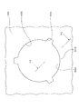
- FIG. 6 is an enlarged plan view of the vicinity of an opening (hereinafter referred to as a dial opening) 430 for fitting the dial 105 of the door frame 120.
- a dial opening an opening for fitting the dial 105 of the door frame 120.
- the dial opening 430 has a circular through hole 500 and three recesses 510, and each recess 510 has an isosceles trapezoidal opening.
- the recess 510 passes through the door frame 120.
- the recess 510 communicates with a disk-shaped retaining protrusion receiving recess (not shown) on the surface of the door frame 120 opposite to the operation unit 200 side.
- Each of the concave portions 510 communicates with the through hole 500.
- the three concave portions 510 are equally arranged on the circumference of the through hole 500.
- the inner diameter of the through hole 500 is slightly larger than the outer diameter of the cylindrical portion of the substantially cylindrical fitting portion 210 (see FIG. 3), and the fitting portion 210 can pass through the through hole 500. ing.
- the inner diameter of the virtual circumscribed circle of the three retaining protrusions 225 of the dial 105 is larger than the inner diameter of the through hole 500. For this reason, the three retaining projections 225 cannot pass through the through hole 500.
- an inner diameter of the disc-shaped retaining protrusion receiving recess is larger than an inner diameter of the virtual circumscribed circle.
- the three retaining protrusions 225 can freely rotate in the retaining protrusion accommodating recess.
- each of the recesses 510 has a planar shape corresponding to the planar shape of the retaining projection 225 (see FIG. 3) of the dial 105.
- Each recess 510 has a slightly larger opening area than the retaining projection 225 of the dial 105 so that the retaining projection 225 can pass through the recess 510.
- the encoder button drop prevention structure 700 is assembled as follows.
- the fitting portion 210 (see FIG. 3) of the dial 105 is passed through the through hole 500 (see FIG. 6)
- the fitting portion 210 (see FIG. 6) is moved to the distal end side of the outer peripheral surface of the rotating portion 330 (see FIG. 4) of the rotary encoder 320.
- the end portion of the inner claw 230 of the fitting portion 210 is hooked on the annular groove 340 of the rotary encoder 320 (see FIG. 4).
- the dial 105 is appropriately rotated until the three retaining projections 225 of the fitting part 210 and the circumferential phase of the concave part 510 of the rotary encoder 320 coincide with each other.
- the dial 105 is pushed toward the rotary encoder 320 in a state where the circumferential direction phases of the three retaining protrusions 225 and the concave portion 510 of the rotary encoder 320 coincide with each other.
- the claw 230 is completely engaged with the annular groove 340 of the rotary encoder 320.
- the three retaining protrusions 225 are accommodated in the disk-shaped retaining protrusion accommodating recess on the surface of the door frame 120 opposite to the operation part 200 side. Yes.
- complete engagement of the inner claw 230 of the fitting portion 210 with the annular groove 340 of the rotary encoder 320 can be confirmed by an engagement sound of clicking.
- the dial 105 is appropriately rotated in the circumferential direction, and the three retaining protrusions 225 are rotated in the disk-shaped retaining protrusion accommodating recesses. Then, the three retaining protrusions 225 and the circumferential phase of the concave portion 510 of the rotary encoder 320 are brought into a mismatched state. In this way, the assembly of the encoder button drop prevention structure 700 including the dial 105, the door frame 120, and the rotary encoder 320 is completed.
- FIG. 7 is a schematic cross-sectional view of the encoder button drop prevention structure 700.
- 105 is a dial
- 200 is an operation unit
- 330 is a rotation unit of the rotary encoder 320.
- Reference numeral 300 denotes a circuit board
- 120 denotes a door frame. As shown in FIG. 7, the door frame 120 has a through hole 500.
- the fitting portion 210 of the dial 105 is externally fitted to the rotating portion 320 of the rotary encoder 320.
- FIG. 8 is a schematic sectional view taken along line F8-F8 in FIG.
- a C surface cut (chamfering) is applied to a portion 570 around the through hole 500 of the door frame 120. Further, the chamfering is smoothly performed so that the edge does not stand.
- the drop-out protrusion 225 in the state where the inner claw 230 of the dial 105 is fitted in the engagement groove 340 of the rotary encoder 320, the drop-out protrusion 225 has the operation portion of the recess 510.
- the three retaining protrusions 225 are located on the side opposite to the 200 side, and can pass through the three recesses 510 only when the circumferential phases of the three recesses 510 coincide with each other.
- the user has a large force at the three retaining protrusions 225 where the three recesses 510 are not in phase with the three recesses 510, specifically, at a place other than the removable part that is only one place during one rotation.
- the retaining protrusion 225 is formed on a surface continuous with the opening on the side opposite to the operation unit 200 side of the recess 510 of the door frame 120.
- the dial 105 is reliably prevented from being separated from the door frame 120 by a predetermined distance or more. Therefore, the dial 105 from the rotary encoder 320 does not come off.
- the dial 105 when it is necessary to disassemble the encoder button drop prevention structure 700 during maintenance or the like, the dial 105 is appropriately rotated appropriately.
- the encoder button disconnection prevention structure 700 can be easily and smoothly disassembled by simply pulling out the dial 105 in a state where the three retaining protrusions 225 are in phase with the three recesses 510 in the circumferential direction. . Therefore, maintenance can be performed easily and smoothly.
- the inner claw 230 has the flat surface portion 231 on the surface facing the inner side in the radial direction.
- the static friction coefficient with the engaging groove 340 can be lowered. Therefore, the rotary encoders 225 can apply a force of a certain level or more, even if the three retaining protrusions 225 are not pulled with an excessively large force at a position where the circumferential direction phase coincides with the three recesses 510.
- the inner claw 230 of the dial 105 can be removed from the engagement groove 340 of 320. Therefore, maintenance requiring disassembly of the dial 105 can be easily performed.
- the fitting portion 210 and a portion 570 in which a portion around the through hole 500 of the door frame 120 is cut in a C plane see FIG. 6
- the planar shape of the retaining protrusion 225 and the shape of the opening of the recess 510 are substantially isosceles trapezoidal shapes.
- the planar shape and the shape of the opening of the recess may be any shape such as a rectangular shape or a semicircular shape.
- the retaining protrusions 225 and the recesses 510 are equally arranged in the circumferential direction.
- the retaining protrusions and the recesses are arranged in the circumferential direction. May be arranged one by one, or 2 or N (N is a natural number of 4 or more) or the like may be arranged in the circumferential direction.
- a plurality of retaining protrusions and recesses may be arranged at intervals that are not equal in the circumferential direction.
- the number of the retaining protrusions 225 and the number of the recesses 510 are equal, but in this invention, the number of the retaining protrusions is larger than the number of the recesses. It may be less. In this case, at the time of assembling the structure for preventing the encoder button from coming off, the phases of all the retaining protrusions are the same as the number of the recessed parts in the plurality of recessed parts. Needless to say.
- the drop prevention protrusion 225 is accommodated in the drop prevention protrusion accommodating recess located on the surface of the door frame 120 opposite to the operation part 200 side. It was. However, in the present invention, there is no need to have the retaining projection receiving recess on the surface of the door frame opposite to the operation portion side, and the retaining projection can be freely synchronized with the rotation of the operation portion.
- the surface of the door frame opposite to the operation unit side may have any shape as long as it can rotate.
- the recess may not communicate with the door frame, and the recess may communicate with the retaining projection housing chamber formed in the door frame.
- the retaining protrusion accommodating chamber has a radial cross-sectional area that can accommodate the virtual circumscribed circle of the retaining protrusion.
- the engaging portion is the inner claw 230.
- the engaging portion is a spline, a serration or the like, and the engaging groove Is a spline groove or serration groove, etc., and the encoder button fitting portion and the rotary encoder rotation portion may rotate synchronously by spline engagement or serration engagement.
- the engaging portion may be an inner peripheral surface or an outer peripheral surface of the fitting portion, and the fitting portion may be press-fitted into the rotating portion of the rotary encoder by external fitting or internal fitting.
- the encoder button drop prevention structure 700 of the above embodiment is part of a steam cooker.
- the encoder button omission prevention structure of the present invention may be a part of a heating cooker such as an oven, a range, an oven range, or an IH cooking heater that does not use superheated steam, and an oven that uses superheated steam, It may be part of a cooking device such as a range or IH cooking heater.
- the encoder button disconnection preventing structure of the present invention may be a part of various measuring devices.
Landscapes
- Engineering & Computer Science (AREA)
- Chemical & Material Sciences (AREA)
- Combustion & Propulsion (AREA)
- Mechanical Engineering (AREA)
- General Engineering & Computer Science (AREA)
- Electric Ovens (AREA)
Abstract
Description
静止部と、この静止部に対する回転部とを有し、この回転部の外周面に、軸方向に延びると共に、互いに周方向に間隔をおいて位置する複数の係合溝を有するロータリーエンコーダと、
外周面を有する操作部と、上記操作部の中央側から軸方向に突出すると共に、上記回転部に嵌合する略筒状の嵌合部と、上記嵌合部に設けられて、上記係合溝に係合する係合部と、上記嵌合部から径方向の外方に周方向に互いに間隔をおいて突出する少なくとも1つの抜け止め突出部とを有するエンコーダボタンと、
上記嵌合部が挿入される貫通穴と、上記抜け止め突出部が通過可能な少なくとも1つの凹部とを有する板状部材と
を備え、
上記抜け止め突出部は、上記凹部と周方向の位相が一致したときに、上記凹部を通過可能であると共に、上記抜け止め突出部と、上記凹部との位相が一致していないときに、上記板状部材に軸方向に係止されることを特徴としている。
上記係合部は、上記嵌合部の上記操作部側とは反対側の先端部からレ字状に径方向の内側に屈曲する内爪であり、
上記内爪は、径方向の内方を向いている面に平面部を有している。
上記エンコーダボタンは、上記嵌合部と、上記操作部とを連結する連結部を有し、
上記板状部材の上記貫通穴の周辺の部分には、C面カットが施されている。
120 ドアフレーム
200 操作部
210 嵌合部
220 連結部
225 抜け止め突出部
230 内爪
231 平面部
320 ロータリーエンコーダ
330 回転部
340 係合溝
341 静止部
430 ダイヤル用開口
500 貫通穴
510 凹部
570 ドアフレームの貫通穴の周辺の部分
700 エンコーダボタンの抜け防止構造
Claims (3)
- 静止部と、この静止部に対する回転部とを有し、この回転部の外周面に、軸方向に延びると共に、互いに周方向に間隔をおいて位置する複数の係合溝を有するロータリーエンコーダと、
外周面を有する操作部と、上記操作部の中央側から軸方向に突出すると共に、上記回転部に嵌合する略筒状の嵌合部と、上記嵌合部に設けられて、上記係合溝に係合する係合部と、上記嵌合部から径方向の外方に周方向に互いに間隔をおいて突出する少なくとも1つの抜け止め突出部とを有するエンコーダボタンと、
上記嵌合部が挿入される貫通穴と、上記抜け止め突出部が通過可能な少なくとも1つの凹部とを有する板状部材と
を備え、
上記抜け止め突出部は、上記凹部と周方向の位相が一致したときに、上記凹部を通過可能であると共に、上記抜け止め突出部と、上記凹部との位相が一致していないときに、上記板状部材に軸方向に係止されることを特徴とするエンコーダボタンの抜け防止構造。 - 請求項1に記載のエンコーダボタンの抜け防止構造において、
上記係合部は、上記嵌合部の上記操作部側とは反対側の先端部からレ字状に径方向の内側に屈曲する内爪であり、
上記内爪は、径方向の内方を向いている面に平面部を有していることを特徴とするエンコーダボタンの抜け防止構造。 - 請求項1または2に記載のエンコーダボタンの抜け防止構造において、
上記エンコーダボタンは、上記嵌合部と、上記操作部とを連結する連結部を有し、
上記板状部材の上記貫通穴の周辺の部分には、C面カットが施されていることを特徴とするエンコーダボタンの抜け防止構造。
Priority Applications (4)
| Application Number | Priority Date | Filing Date | Title |
|---|---|---|---|
| CN2010800256516A CN102804310A (zh) | 2009-06-11 | 2010-06-11 | 编码器旋钮的防脱结构 |
| JP2011518579A JPWO2010143703A1 (ja) | 2009-06-11 | 2010-06-11 | エンコーダボタンの抜け防止構造 |
| EP10786234.4A EP2442336A4 (en) | 2009-06-11 | 2010-06-11 | STRUCTURE FOR PREVENTING AN ENCODER BUTTON TO DELIBERATE |
| US13/377,208 US20120087721A1 (en) | 2009-06-11 | 2010-06-11 | Structure for preventing encoder button from coming out of place |
Applications Claiming Priority (2)
| Application Number | Priority Date | Filing Date | Title |
|---|---|---|---|
| JP2009140252 | 2009-06-11 | ||
| JP2009-140252 | 2009-06-11 |
Publications (1)
| Publication Number | Publication Date |
|---|---|
| WO2010143703A1 true WO2010143703A1 (ja) | 2010-12-16 |
Family
ID=43308958
Family Applications (1)
| Application Number | Title | Priority Date | Filing Date |
|---|---|---|---|
| PCT/JP2010/059901 Ceased WO2010143703A1 (ja) | 2009-06-11 | 2010-06-11 | エンコーダボタンの抜け防止構造 |
Country Status (5)
| Country | Link |
|---|---|
| US (1) | US20120087721A1 (ja) |
| EP (1) | EP2442336A4 (ja) |
| JP (1) | JPWO2010143703A1 (ja) |
| CN (1) | CN102804310A (ja) |
| WO (1) | WO2010143703A1 (ja) |
Families Citing this family (5)
| Publication number | Priority date | Publication date | Assignee | Title |
|---|---|---|---|---|
| CN104733205B (zh) * | 2013-12-24 | 2018-07-17 | 欧姆龙株式会社 | 旋钮以及电子器件 |
| CN107275141B (zh) * | 2016-04-07 | 2019-09-27 | 佛山市顺德区美的电热电器制造有限公司 | 一种防拔出旋钮及具有其的控制盒和电热器具 |
| FR3057989B1 (fr) * | 2016-10-20 | 2018-11-02 | Groupe Brandt | Dispositif de commande manuelle pour un appareil electromenager |
| CN108733131A (zh) * | 2017-04-20 | 2018-11-02 | 深圳市三诺数字科技有限公司 | 一种旋钮侧边旋转结构及电子装置 |
| CN109846376A (zh) * | 2019-01-15 | 2019-06-07 | 吴丽萍 | 蒸汽烤箱控制界面及其控制方法 |
Citations (6)
| Publication number | Priority date | Publication date | Assignee | Title |
|---|---|---|---|---|
| JPS61166421U (ja) * | 1985-04-02 | 1986-10-15 | ||
| JPH0389773U (ja) * | 1989-12-28 | 1991-09-12 | ||
| JP2001014971A (ja) * | 1999-06-28 | 2001-01-19 | Hitachi Ltd | 操作釦取付構造 |
| JP2003123594A (ja) * | 2001-10-15 | 2003-04-25 | Japan Aviation Electronics Industry Ltd | 多方向スイッチ |
| JP2005197070A (ja) | 2004-01-07 | 2005-07-21 | Kenwood Corp | プッシュスイッチ付回転型電子部品 |
| JP2005228549A (ja) * | 2004-02-12 | 2005-08-25 | Matsushita Electric Ind Co Ltd | 操作つまみの中点復帰機構およびそれを用いて構成された回転型電子部品 |
Family Cites Families (14)
| Publication number | Priority date | Publication date | Assignee | Title |
|---|---|---|---|---|
| US4175220A (en) * | 1977-12-07 | 1979-11-20 | Westinghouse Electric Corp. | Convertible selector switch |
| DE2847140C2 (de) * | 1978-10-30 | 1980-12-04 | Siemens Ag, 1000 Berlin Und 8000 Muenchen | In eine Gehäuseöffnung, insbesondere eines Spielzeugtransformators, von außen eingesteckter Drehknopf |
| US4486918A (en) * | 1983-04-29 | 1984-12-11 | Motorola, Inc. | Snap action removable knob |
| DE3511872A1 (de) * | 1985-04-01 | 1986-10-02 | BSG-Schalttechnik GmbH & Co KG, 7460 Balingen | Dreh- oder schiebepotentiometer (stufenschalter) und verfahren zu seiner herstellung |
| US4653708A (en) * | 1985-12-16 | 1987-03-31 | Hamilton Standard Controls, Inc. | Twist-in mounting for a thermostat |
| JPH01129804U (ja) * | 1988-02-26 | 1989-09-04 | ||
| JP3557978B2 (ja) * | 2000-01-04 | 2004-08-25 | 株式会社村田製作所 | 可変抵抗器 |
| JP2003217397A (ja) * | 2002-01-25 | 2003-07-31 | Matsushita Electric Ind Co Ltd | 回転操作型電子部品 |
| KR100485844B1 (ko) * | 2002-06-28 | 2005-04-28 | 삼성전자주식회사 | 네비게이션 스위치 조립체 |
| JP4075590B2 (ja) * | 2002-11-27 | 2008-04-16 | 松下電器産業株式会社 | 回転型電子部品 |
| JP2006260943A (ja) * | 2005-03-17 | 2006-09-28 | Matsushita Electric Ind Co Ltd | 照光付き回転型電子部品の実装構造 |
| JP2006310441A (ja) * | 2005-04-27 | 2006-11-09 | Matsushita Electric Ind Co Ltd | 回転型電子部品 |
| JP4765855B2 (ja) * | 2006-09-13 | 2011-09-07 | パナソニック株式会社 | スイッチ装置 |
| KR101309298B1 (ko) * | 2007-05-25 | 2013-09-17 | 삼성전자주식회사 | 세탁기 및 그 컨트롤 패널 어셈블리 |
-
2010
- 2010-06-11 EP EP10786234.4A patent/EP2442336A4/en not_active Withdrawn
- 2010-06-11 WO PCT/JP2010/059901 patent/WO2010143703A1/ja not_active Ceased
- 2010-06-11 JP JP2011518579A patent/JPWO2010143703A1/ja active Pending
- 2010-06-11 CN CN2010800256516A patent/CN102804310A/zh active Pending
- 2010-06-11 US US13/377,208 patent/US20120087721A1/en not_active Abandoned
Patent Citations (6)
| Publication number | Priority date | Publication date | Assignee | Title |
|---|---|---|---|---|
| JPS61166421U (ja) * | 1985-04-02 | 1986-10-15 | ||
| JPH0389773U (ja) * | 1989-12-28 | 1991-09-12 | ||
| JP2001014971A (ja) * | 1999-06-28 | 2001-01-19 | Hitachi Ltd | 操作釦取付構造 |
| JP2003123594A (ja) * | 2001-10-15 | 2003-04-25 | Japan Aviation Electronics Industry Ltd | 多方向スイッチ |
| JP2005197070A (ja) | 2004-01-07 | 2005-07-21 | Kenwood Corp | プッシュスイッチ付回転型電子部品 |
| JP2005228549A (ja) * | 2004-02-12 | 2005-08-25 | Matsushita Electric Ind Co Ltd | 操作つまみの中点復帰機構およびそれを用いて構成された回転型電子部品 |
Non-Patent Citations (1)
| Title |
|---|
| See also references of EP2442336A4 |
Also Published As
| Publication number | Publication date |
|---|---|
| JPWO2010143703A1 (ja) | 2012-11-29 |
| EP2442336A4 (en) | 2014-04-16 |
| EP2442336A1 (en) | 2012-04-18 |
| CN102804310A (zh) | 2012-11-28 |
| US20120087721A1 (en) | 2012-04-12 |
Similar Documents
| Publication | Publication Date | Title |
|---|---|---|
| WO2010143703A1 (ja) | エンコーダボタンの抜け防止構造 | |
| US9388992B2 (en) | Gas oven range | |
| US20110132346A1 (en) | Cooking device | |
| US9488377B2 (en) | Gas oven range | |
| JP2011120865A (ja) | 加熱調理器およびその調理方法 | |
| EP1710508A1 (en) | Steam cooking apparatus | |
| RU2418244C2 (ru) | Печь | |
| EP3144597B1 (en) | Cooking device | |
| US20160363326A1 (en) | Multi-ring gas burner | |
| US20170191671A1 (en) | Cooktop Appliance | |
| JP2005282893A (ja) | 加熱調理器 | |
| CN110604461B (zh) | 烹饪器具 | |
| CN113080695A (zh) | 锅盖及多功能锅 | |
| US20160363327A1 (en) | Gas burner | |
| US10386075B2 (en) | Cooktop appliance with a gas burner assembly | |
| EP4249810B1 (en) | Cooking apparatus | |
| KR101671110B1 (ko) | 조리기기 | |
| JP2011075147A (ja) | 加熱調理器 | |
| EP2519775B1 (en) | A cooking device comprising a knob | |
| JP4278629B2 (ja) | 加熱調理器 | |
| JP5140037B2 (ja) | プッシュボタンのぐらつき防止構造 | |
| JP4473043B2 (ja) | 蒸気調理器 | |
| JP4664250B2 (ja) | 加熱調理器 | |
| KR100766113B1 (ko) | 빌트인용 전기 레인지 | |
| JP2007032961A (ja) | 加熱調理器 |
Legal Events
| Date | Code | Title | Description |
|---|---|---|---|
| WWE | Wipo information: entry into national phase |
Ref document number: 201080025651.6 Country of ref document: CN |
|
| 121 | Ep: the epo has been informed by wipo that ep was designated in this application |
Ref document number: 10786234 Country of ref document: EP Kind code of ref document: A1 |
|
| WWE | Wipo information: entry into national phase |
Ref document number: 2011518579 Country of ref document: JP |
|
| WWE | Wipo information: entry into national phase |
Ref document number: 13377208 Country of ref document: US |
|
| NENP | Non-entry into the national phase |
Ref country code: DE |
|
| WWE | Wipo information: entry into national phase |
Ref document number: 2010786234 Country of ref document: EP |
|
| WWE | Wipo information: entry into national phase |
Ref document number: 221/CHENP/2012 Country of ref document: IN |