WO2010147186A1 - 鞍乗型車両のエアバッグ装置 - Google Patents
鞍乗型車両のエアバッグ装置 Download PDFInfo
- Publication number
- WO2010147186A1 WO2010147186A1 PCT/JP2010/060307 JP2010060307W WO2010147186A1 WO 2010147186 A1 WO2010147186 A1 WO 2010147186A1 JP 2010060307 W JP2010060307 W JP 2010060307W WO 2010147186 A1 WO2010147186 A1 WO 2010147186A1
- Authority
- WO
- WIPO (PCT)
- Prior art keywords
- lid
- airbag
- air bag
- type vehicle
- holding box
- Prior art date
- Legal status (The legal status is an assumption and is not a legal conclusion. Google has not performed a legal analysis and makes no representation as to the accuracy of the status listed.)
- Ceased
Links
Images


Classifications
-
- B—PERFORMING OPERATIONS; TRANSPORTING
- B60—VEHICLES IN GENERAL
- B60R—VEHICLES, VEHICLE FITTINGS, OR VEHICLE PARTS, NOT OTHERWISE PROVIDED FOR
- B60R21/00—Arrangements or fittings on vehicles for protecting or preventing injuries to occupants or pedestrians in case of accidents or other traffic risks
- B60R21/02—Occupant safety arrangements or fittings, e.g. crash pads
- B60R21/16—Inflatable occupant restraints or confinements designed to inflate upon impact or impending impact, e.g. air bags
- B60R21/20—Arrangements for storing inflatable members in their non-use or deflated condition; Arrangement or mounting of air bag modules or components
- B60R21/215—Arrangements for storing inflatable members in their non-use or deflated condition; Arrangement or mounting of air bag modules or components characterised by the covers for the inflatable member
- B60R21/216—Arrangements for storing inflatable members in their non-use or deflated condition; Arrangement or mounting of air bag modules or components characterised by the covers for the inflatable member comprising tether means for limitation of cover motion during deployment
-
- B—PERFORMING OPERATIONS; TRANSPORTING
- B62—LAND VEHICLES FOR TRAVELLING OTHERWISE THAN ON RAILS
- B62J—CYCLE SADDLES OR SEATS; AUXILIARY DEVICES OR ACCESSORIES SPECIALLY ADAPTED TO CYCLES AND NOT OTHERWISE PROVIDED FOR, e.g. ARTICLE CARRIERS OR CYCLE PROTECTORS
- B62J27/00—Safety equipment
- B62J27/20—Airbags specially adapted for motorcycles or the like
-
- B—PERFORMING OPERATIONS; TRANSPORTING
- B60—VEHICLES IN GENERAL
- B60R—VEHICLES, VEHICLE FITTINGS, OR VEHICLE PARTS, NOT OTHERWISE PROVIDED FOR
- B60R21/00—Arrangements or fittings on vehicles for protecting or preventing injuries to occupants or pedestrians in case of accidents or other traffic risks
- B60R2021/0065—Type of vehicles
- B60R2021/0088—Cycles, e.g. motorcycles
-
- B—PERFORMING OPERATIONS; TRANSPORTING
- B60—VEHICLES IN GENERAL
- B60R—VEHICLES, VEHICLE FITTINGS, OR VEHICLE PARTS, NOT OTHERWISE PROVIDED FOR
- B60R21/00—Arrangements or fittings on vehicles for protecting or preventing injuries to occupants or pedestrians in case of accidents or other traffic risks
- B60R21/02—Occupant safety arrangements or fittings, e.g. crash pads
- B60R21/16—Inflatable occupant restraints or confinements designed to inflate upon impact or impending impact, e.g. air bags
- B60R2021/161—Inflatable occupant restraints or confinements designed to inflate upon impact or impending impact, e.g. air bags characterised by additional means for controlling deployment trajectory
-
- B—PERFORMING OPERATIONS; TRANSPORTING
- B60—VEHICLES IN GENERAL
- B60R—VEHICLES, VEHICLE FITTINGS, OR VEHICLE PARTS, NOT OTHERWISE PROVIDED FOR
- B60R21/00—Arrangements or fittings on vehicles for protecting or preventing injuries to occupants or pedestrians in case of accidents or other traffic risks
- B60R21/02—Occupant safety arrangements or fittings, e.g. crash pads
- B60R21/16—Inflatable occupant restraints or confinements designed to inflate upon impact or impending impact, e.g. air bags
- B60R21/20—Arrangements for storing inflatable members in their non-use or deflated condition; Arrangement or mounting of air bag modules or components
- B60R21/215—Arrangements for storing inflatable members in their non-use or deflated condition; Arrangement or mounting of air bag modules or components characterised by the covers for the inflatable member
- B60R21/216—Arrangements for storing inflatable members in their non-use or deflated condition; Arrangement or mounting of air bag modules or components characterised by the covers for the inflatable member comprising tether means for limitation of cover motion during deployment
- B60R2021/2163—Arrangements for storing inflatable members in their non-use or deflated condition; Arrangement or mounting of air bag modules or components characterised by the covers for the inflatable member comprising tether means for limitation of cover motion during deployment with energy absorbing or elastic means
-
- B—PERFORMING OPERATIONS; TRANSPORTING
- B60—VEHICLES IN GENERAL
- B60R—VEHICLES, VEHICLE FITTINGS, OR VEHICLE PARTS, NOT OTHERWISE PROVIDED FOR
- B60R21/00—Arrangements or fittings on vehicles for protecting or preventing injuries to occupants or pedestrians in case of accidents or other traffic risks
- B60R21/02—Occupant safety arrangements or fittings, e.g. crash pads
- B60R21/16—Inflatable occupant restraints or confinements designed to inflate upon impact or impending impact, e.g. air bags
- B60R21/26—Inflatable occupant restraints or confinements designed to inflate upon impact or impending impact, e.g. air bags characterised by the inflation fluid source or means to control inflation fluid flow
- B60R21/263—Inflatable occupant restraints or confinements designed to inflate upon impact or impending impact, e.g. air bags characterised by the inflation fluid source or means to control inflation fluid flow using a variable source, e.g. plural stage or controlled output
Definitions
- the present invention relates to an improvement of an airbag device for a straddle-type vehicle.
- Patent Document 1 There is known an air bag device of a straddle type vehicle provided in front of a passenger seat and configured to expand and deploy when the vehicle receives a predetermined impact (for example, Patent Document 1 and Patent Document 2).
- a seat on which a passenger is seated is attached to a vehicle body frame, a fuel tank is provided in front of the seat, and a bag in which the air bag is stored in front of the fuel tank
- the housing is arranged. From the middle part of the rear face of the airbag, a bag anchor extends to the rear of the vehicle, and the tip of the bag anchor is connected to the vehicle body frame below the seat.
- a lid covering the upper surface of the bag housing opens upward with a hinge provided at the front of the bag housing as a fulcrum.
- the airbag then deploys out of the bag housing.
- the bag anchor extends to exert a anchoring action to hold the airbag in a predetermined position.
- Patent Document 1 a bag anchor is an essential element.
- the tip of the bag anchor comes out of the bag housing and extends to the vehicle body frame 1, the appearance is affected. Therefore, the abolition of the bag anchor is desired.
- Patent Document 2 has been proposed to meet this demand.
- a seat is attached to a vehicle body frame, a bag housing for storing the air bag is disposed immediately in front of the seat, and a fuel tank is provided in front of the bag housing. It has a structure.
- the airbag apparatus As the air bag begins to deploy, the lid covering the top of the bag housing opens upward. Then, the airbag is deployed almost directly upward. That is, the airbag apparatus according to Patent Document 2 arranges the bag housing at a position immediately in front of the seat on which the occupant sits, and omits the tether by shortening the distance between the occupant and the bag housing. It is characterized by
- Patent No. 3592447 gazette Patent No. 3685872
- An object of the present invention is to provide an air bag device for a straddle-type vehicle that enables the air bag to be deployed in a preferable direction.
- an airbag apparatus for a straddle-type vehicle comprising: a holding box provided on a vehicle body frame at a position immediately before an occupant seat on which an occupant sits; An airbag that is deployed in front of the occupant, a lid that closes the opening of the holding box, and a hinge that is provided on the vehicle rear side of the lid and serves as a pivot of the lid when the airbag is deployed.
- lid regulation means for regulating the opening angle of the lid is provided between the lid and the holding box.
- the lid includes left and right lid stays integrally provided, and the lid restricting means is provided on each of the left and right lid stays.
- the lid regulation means is a link mechanism.
- the lid regulation means is a belt-like member.
- the lid stay is insert-molded on the lid.
- the lid restricting means is set so that the deployment angle of the lid does not exceed 90 ° with respect to the road surface.
- the belt-like member has a fragile portion formed along the longitudinal direction of the belt-like member
- the holding box includes a fastening member for holding one end of the fragile portion
- the lid is the fastening It was made to open to a predetermined angle, cutting the above-mentioned fragile part with a member.
- the belt-like member is integrally formed left and right, passes through the inside of the lid, and is held by a guide member provided on the inside of the lid, and the belt-like member is between the guide member and the lid And the lid is opened to a predetermined angle.
- the air bag device includes lid control means for controlling the opening angle of the lid between the lid and the holding box.
- lid control means for controlling the opening angle of the lid between the lid and the holding box.
- the lid By providing the left and right integrated lid stays in the lid, when the lid is deployed, the impact received from the lid regulating means can be uniformly received by the lid. As a result, shape design of the lid becomes easy.
- the lid regulating means is a link mechanism
- the links extend linearly when the lid is opened. Since the links extend in a straight line and the linearly extending links guide the air bag and the air bag is less likely to spread outside the links, the direction in which the air bag is deployed can be directed to the required area.
- the lid regulation means is a belt-like member. If it is a strip
- the lid stay is insert-molded on the lid, the lid stay can be integrated on the lid without using a fastening member. Therefore, it is possible to suppress the increase in the number of parts.
- the deployment angle of the lid is set so as not to exceed 90 ° with respect to the road surface, so that the airbag can be deployed from the front to the top of the holding box. With such an angle setting, even when the occupant has moved forward, the airbag can be deployed forward and upward reliably.
- the band-like member is provided with the fragile portion, and the lid is opened to a predetermined angle while the fragile portion is cut by the fastening member provided in the holding box, so the lid is opened when the air bag is opened. You can reduce the speed.
- the belt-like members are integrally formed left and right, pass through the inside of the lid, are held by the guide members provided on the inside of the lid, and are restricted by the guide members so that the lid is opened to a predetermined angle.
- the speed at which the lid opens can be reduced.
- FIG. 1 is a left side view of a motorcycle provided with an airbag device according to a first embodiment of the present invention.
- FIG. 2 is a plan view of the airbag module with the lid and the airbag shown in FIG. 1 being removed.
- FIG. 3 is a bottom view of the airbag module shown in FIG. 2;
- Fig. 4 is an enlarged cross-sectional view taken along line 4-4 of Fig. 1;
- FIG. 5 is a cross-sectional view taken along line 5-5 of FIG. 4;
- FIG. 3 is a perspective view of the airbag module shown in FIG. 2;
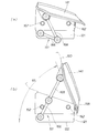
- FIG. 7 is an operation view of a lid restricting means provided in the air bag module shown in FIG. 6.
- FIG. 1 is an operation view of a motorcycle provided with an air bag device according to a first embodiment.
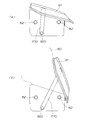
- FIG. 7 is a configuration and an operation view of a lid restricting means provided in an air bag module according to a second embodiment.
- FIG. 7 is a configuration and an operation view of an air bag module according to a third embodiment.
- FIG. 16 is a perspective view of an air bag module according to a fourth embodiment. It is an action view of the air bag module shown by FIG.
- a motorcycle 10 as a straddle-type vehicle includes a head pipe 11 and a vehicle body frame 12 extending from the head pipe 11 toward the rear of the vehicle body.
- the body frame 12 includes a head pipe 11 forming a front portion of the vehicle body 14, a main frame 15 extending rearward from the head pipe 11, and a pivot having a pivot shaft 16 attached to a rear end of the main frame 15.
- the plate 17, the back of the pivot plate 17 rising obliquely upward from the top of the pivot plate 17, and then the rearwardly extending seat rail 18, the rear end of the seat rail 18 and the middle portion of the pivot plate 17 are connected And a middle frame 19 for supporting the seat rail 18. That is, the rear portion of the vehicle body frame 12 includes the seat rail 18.
- Below the pivot plate 17 is mounted an occupant step 20 on which the driver's foot is placed.
- a sub rail 21 extends from the upper end of the middle frame 19 toward the rear of the vehicle.
- the rear portions of the sub rails 21 and the middle frame 19 are connected by a seat stay 22.
- an auxiliary stay 23 extends obliquely rearward and downward from the rear of the seat stay 22 and horizontally in the front.
- a trunk 27 for storing objects is attached to the sub rail 21, and a backrest 28 for holding the back of the occupant is attached to the front wall 27a of the trunk 27.
- the main frame 15, the pivot plate 17, the seat rail 18, the middle frame 19, the occupant step 20, the sub rail 21, the seat stay 22, and the auxiliary stay 23 are provided symmetrically with respect to the center in the vehicle width direction.
- the engine 32 is suspended by fastening members 31a to 31c.
- the engine 32 is, for example, a horizontally opposed six-cylinder water-cooled engine.
- a rear swing arm 34 capable of swinging up and down about the pivot shaft 16 is attached to the pivot plate 17, and a rear shaft 35 is provided at the rear end of the rear swing arm 34. Is rotatably attached.
- the rear wheel 36 is driven by a chain 42 wound between a drive sprocket 38 attached to a drive shaft 37 of the engine 32 and a driven sprocket 41 integrated with the rear wheel 36.
- a link mechanism 47 is provided on the rear swing arm 34, the lower end of the rear cushion unit 48 is attached to the link mechanism 47, and the upper end of the rear cushion unit 48 is attached to a bracket 49 formed on the main frame 15 side. There is.
- a front fork 52 is rotatably attached to the head pipe 11, and a front wheel axle 53 is provided on the front fork 52.
- a front wheel 54 is rotatably attached to the front wheel axle 53, and an upper end of the front fork 52 , Steering handle 55 is attached.
- the head pipe 11 is a member for rotatably supporting the steering handle 55.
- a main cowl 56 is provided on the front side of the main frame 15, and an opening 57 is formed on the side of the main cowl 56.
- a radiator unit 58 for cooling the engine 32 to face the opening 57. Is arranged.
- a front fender 66 is provided above the front wheel 54, and a front disk plate 62 integrated with the front wheel 54 is attached.
- a front disk brake unit 61 provided to hold the front disk plate 62 for braking is applied to the front
- the fork 52 is provided.
- a front cowl 63 covering the front of the vehicle is disposed in front of the head pipe 11, and a front shield 64 is extended above the front cowl 63.
- a main stand bracket 68 is provided at the lower end of the pivot plate 17, and a main stand 69 is attached to the main stand bracket 68.
- a battery 67 is disposed below the occupant's seat 71. Behind the front shield 64, a meter 70 is disposed.
- the passenger seat 71 is an integral unit of a front seat 72 and a rear seat 73 provided in series behind the front seat 72.
- the air bag module 82 is one of the elements constituting the air bag device 86.
- the air bag device 86 mainly includes an air bag module 82 and an air bag control unit 87 that controls the deployment of the air bag 150 (FIG. 4) stored in the air bag module 82.
- the air bag module 82 is disposed near the front of the passenger seat 71.
- the air bag module 82 includes a holding box 121 as a case body. That is, the holding box 121 is provided immediately in front of the occupant seat 71 on which the occupant sits.
- a first sensor 77 and a second sensor 78 for detecting an impact applied to the vehicle body 14 are disposed at the upper and lower portions of the front fork 52, respectively.
- a first cable 79 extends from these upper and lower sensors 77, 78.
- the first cable 79 passes above the engine 32 and is connected to the air bag control unit 87.
- the meter 70 is provided with an indicator 80 for indicating normality or abnormality of the air bag device 86, and a second cable 85 extends from the indicator 80.
- the second cable 85 is connected to the air bag control unit 87.
- a third cable 88 extends from the battery 67.
- the third cable 88 passes below the occupant seat 71 and is connected to the air bag control unit 87.
- the first sensor 77, the second sensor 78, and the first cable 79 are disposed in a pair at left and right fork portions provided on the front fork 52, respectively.
- the inflator comprises a left inflator 111 disposed on the left side in the vehicle width direction center and a right inflator 112 disposed on the right side in the vehicle width direction center.
- the two left and right inflators 111 and 112 generate different amounts of gas from each other.
- the size of the left inflator 111 is larger than that of the right inflator 112. Therefore, the gas generation amount of the left inflator 111 is larger than the gas generation amount of the right inflator 112.
- the left inflator 111 is provided with a mounting flange portion 115 projecting outward from the outer wall 113.
- the right inflator 112 is provided with a mounting flange portion 116 projecting outward from the outer wall 114.
- the holding box 121 includes a bottom plate 122 and left and right walls 123 and 124 and front and back walls 125 and 126 raised from the bottom plate 122.
- the bottom plate 122 is provided with left and right holes 127, 128 sized to allow the lower part of each inflator to pass therethrough.
- the left and right inflators 111 and 112 are mounted on the bottom plate 122 so as to fit into the left and right holes 127 and 128, and the flange portions 115 and 116 formed on the left and right inflators are pressed from above by the bag ring 131.
- the lower portion 133 of the left inflator is fitted in the left hole 127 provided in the bottom plate 122, and the lower portion 134 of the right inflator is fitted in the right hole 128 provided in the bottom plate 122.
- Each nut 136 is tightened to eight screws 135.
- the flange portions 115 and 116 (FIG. 2) are sandwiched and fixed by the bottom plate 122 and the bag ring 131 (FIG. 2).
- the left and right inflators 111 and 112 are attached to the holding box 121.
- the lid 141 is a member for closing the opening 142 opened to the upper side of the holding box 121, and the cover portion 143 covering the opening 142 extends downward from the vicinity of the left end of the cover portion 143.
- a left fragile portion 147 is formed at the middle in the height direction of the left vertical wall, which breaks when the air bag 150 is deployed, and is broken when the air bag 150 is deployed at the middle in the height direction of the right vertical wall.
- the right fragile portion 148 is formed.
- a left link mechanism 151 is disposed on the outer side of the left vertical wall 145 to restrict the opening angle of the lid 141 when the air bag 150 is deployed.
- a right link mechanism 152 is disposed which regulates the opening angle of the lid 141 when the air bag 150 is deployed.
- the lid 141 covers the opening portion 142 of the holding box 121, and the front vertical wall 155 extended downward from the front end portion 153 of the cover portion and attached to the front wall 125 of the holding box 121. And a rear vertical wall 156 extending downward from the rear end portion 154 of the cover portion and attached to the rear wall 126 of the holding box 121.
- a front weak portion 157 is formed at the middle in the height direction of the front vertical wall 155, which breaks when the air bag 150 is deployed and the lid 141 is opened, and the air bag is formed at the middle in the height direction of the rear vertical wall 156.
- a hinge portion 158 is formed as a pivot of the lid 141 when the lid 150 is opened and the lid 150 is opened. That is, the hinge portion 158 is provided on the vehicle rear side of the lid 141.
- a lid stay 161 extends from the cover portion 143 of the lid in the front and back direction (left and right direction of the lid) in the figure.
- the lid stay 161 is insert-molded in the cover portion 143 of the lid 141.
- the material of the lid stay 161 is metal
- the material of the lid 141 is resin. That is, the metal lid stay 161 is insert-molded on the resin lid 141.
- the lid 141 is fixed to the side of the holding box 121 via a plurality of rivets 162.
- the left link mechanism 151 has a first supporting point 165 attached to the left wall 123 of the holding box 121, a first link 166 extending rearward from the first supporting point 165, and a first link 166.
- the right link mechanism 152 has the same configuration as the left link mechanism 151 described above, and the description thereof will be omitted.
- the lid stay 161 includes a horizontal arm 173, a left vertical arm 171 extending downward from the left end of the horizontal arm 173, and a right vertical arm 172 extending downward from the right end of the horizontal arm 173. . Then, third fulcrums 169 and 169 are attached to the left and right vertical arms 171 and 172 respectively, and tip portions 174 and 174 of the second link 168 are attached pivotably to the third fulcrums 169 and 169. It is done.
- the air bag module 82 includes a holding box 121, an air bag 150 (FIG. 4) accommodated in the holding box 121 and deployed in front of the occupant when inflated, and a lid 141 closing the opening 142 (FIG. 4) of the holding box.
- the hinge portion 158 (FIG. 5), which is provided on the rear side of the lid 141 and serves as a pivot of the lid 141 when the air bag 150 is deployed, and the lid 141 between the lid 141 and the holding box 121.
- the left and right link mechanisms 151 and 152 are provided as lid regulation means for regulating the opening angle.
- a lid stay 161 is integrally provided on the lid 141, and link mechanisms 151 and 152 are attached to the left and right vertical arms 171 and 172 provided on the lid stay 161, respectively.
- the lid seat 161 is formed in a U-shape such that the horizontal arm 173 and the left and right vertical arms 171 and 172 are integrated. That is, the left and right link mechanisms 151 and 152 are connected by the lid stay 161.
- the left and right vertical arms 171, 172 are integrally formed via the horizontal arm 173, so that when the lid 141 is opened, the impact received from the link mechanisms 151, 152 can be evenly received by the lid 141. .
- the holding box 121 is covered by the lid 141.
- the link mechanism 151 as the lid regulating means is provided between the lid 141 and the holding box 121.
- the link mechanism provided on the opposite side acts in the same manner as the link mechanism 151, and the description thereof will be omitted.
- FIG. 7B shows a state in which the lid 141 is opened as the airbag 150 is deployed, and the first link 166 and the second link 168 that constitute the link mechanism 151 extend in a straight line. .
- the link mechanism 151 as the lid regulating means is not provided between the holding box 121 and the lid 141 and the opening angle of the lid 141 is not regulated, it is difficult for the airbag 150 to be restricted forward and upward. .
- the link mechanisms 151 and 152 as the lid regulating means are provided.
- the opening angle of the lid 141 to ⁇ 1
- the air bag 150 can be restricted from expanding upward, and can be developed forward of the occupant.
- the airbag 150 is deployed to a preferable position.
- the airbag can be deployed in a preferable direction, for example, when the occupant is moved forward due to an impact.
- ⁇ 1 is an opening angle of the lid 141 with respect to the bottom plate 122 when the hinge portion 158 is an axis, and in the first embodiment, ⁇ 1 is set to 70 °. This ⁇ 1 is also the opening angle of the lid 141 in the air bag module 82.
- the value of ⁇ 1 is a value that can be changed without being limited to 70 °.
- the link mechanism 151 is provided as the lid regulating means, the link 166 extends linearly when the lid 141 is opened. Since the first link 166 and the second link 168 extend in a straight line, and the airbag 150 is guided by the straight links 166 and 168 and the air bag 150 is difficult to spread outside the links 166 and 168, the air The deployment direction of the bag 150 can be directed to the required area.
- the lid stay 161 which is easily applied force made of metal and the lid 141 which covers the upper side of the holding box 121 made of resin, weight reduction of the device is achieved while securing the strength required for the air bag module 82. be able to. Furthermore, if the lid 141 is made of resin, it becomes possible to easily provide a fragile portion (FIG. 4, symbol 147, symbol 148, FIG. 5, symbol 157) formed at the boundary between the lid 141 and the holding box 121. .
- ⁇ 2 is an opening angle of the lid 141 in the vehicle, and the control direction of the airbag 150 when the occupant D gets on is determined by the value of ⁇ 1 and the value of ⁇ 2.
- ⁇ 2 which is the deployment angle of the lid, is 90 ° or more, the airbag will also deploy behind the holding box.
- the deployment angle of the lid 141 is set so as not to exceed 90 ° with respect to the road surface, so the airbag 150 can be deployed from the front to the top of the holding box. With such an angle setting, the air bag 150 can be deployed forward and upward, particularly when the forward movement of the occupant is involved.
- the airbag control unit 87 is disposed between the head pipe 11 and the airbag module 82 in a side view of the vehicle.
- the air bag control unit 87 has delay means 189 for controlling the ignition timings of the left and right two inflators 111 and 112 to be different from each other.
- the left and right inflators 111 and 112 respectively generate different amounts of gas.
- the inflators 111 and 112 can be disposed compactly while securing the required output.
- FIG. 9A shows a state in which the holding box 121 is covered by the lid 141.
- a belt-like member 177 B (webbing) as a lid regulating means is provided between the lid 141 and the holding box 121.
- a fastening member 181 is provided, and on the side of the lid stay (FIG. 5, reference numeral 161), another fastening member 182 is provided, and this fastening member 181 and another fastening member 182
- a belt-like member 177B as a lid regulating member is attached between them.
- the middle portion 183 of the strip-shaped member is provided with a folding portion 184 in which the strip-shaped member is folded so as to open the lid 141 to a predetermined angle.
- the fastening member 181, the another fastening member 182 and the belt-like member 177B are provided one by one respectively on the left and right, but have the same configuration, and description of the lid restricting means provided on the right is omitted.
- FIG. 9B shows a state in which the lid 141 is opened as the airbag 150 is deployed, and the folding portion 184 extends in a straight line. If it is the strip
- the other configurations and functions are not greatly different from the embodiment, and the description will be omitted.
- the major difference from the second embodiment is that the positions of the left and right fastening members 181C are changed upward with respect to the second embodiment, and the beltlike member 177C is a fragile portion along the longitudinal direction.
- a breaking line 186 is provided, and one end of the breaking line 186 provided in the holding box 121 is held by the fastening member 181C, and there is no other significant difference.
- FIG. 10B when the air bag 150 is deployed, the lid 141 is opened to a predetermined angle while cutting the broken line 186 by the fastening member 181C.
- a breaking line 186 is provided on the belt-like member 177C, and the lid 141 is opened to a predetermined angle while cutting the breaking line 186 with the fastening member 181C provided on the holding box 121.
- the strip member 177C passes the breaking line 186, is torn off by the fastening member 181C, and separates from the fastening member 181C. That is, the direction in which the air bag 150 deploys can be directed to the direction in which the occupant is held, and the speed at which the lid 141 opens can be suppressed low when the air bag 150 opens.
- FIG. 11 On the left wall 123 and the right wall 124 constituting the left and right of the holding box 121, fastening members 181D and 181D are respectively provided, and these left and right fastening members 181D and 181D serve as lid restricting means.
- One strip member 177D (webbing) is provided.
- a plate-like stay 188 is insert-molded in the lid 141, and a plurality of friction guide members 187 having a ring shape extend from the stay 188, and the inside of the ring of these friction guide members 187 is a strip member 177D (webbing) Was allowed to pass.
- the belt-like member 177D is provided with a folding portion 184D which can be extended when the lid 141 is opened at an intermediate portion in the longitudinal direction.
- the belt-like member 177D is disposed along the back surface of the lid 141 described above and is guided by the plurality of friction guide members 187 having a ring shape.
- the belt-like member 177D restricts the lid 141 to open at an angle greater than or equal to a predetermined angle when the lid 141 reaches a predetermined opening angle.
- the longitudinal length of the belt-like member 177D is set in accordance with the preset opening angle of the lid 141.
- four friction guide members 187 are attached to the lid 141 for braking the belt member 177D and slowing the opening speed of the lid 141 until the lid 141 opens to a predetermined angle. It is done.
- belt-shaped member 177D (webbing) as this lid control means, the increase in a number of parts can be suppressed compared with the mechanism in which a several member is required, for example. Since the increase in the number of parts can be suppressed, the cost of the air bag module can be reduced.
- FIG. 12A a state in which the holding box 121 is covered by the lid 141 is shown.
- the belt-like member 177D as the lid regulating means does not extend.
- the folded portion 184D of the folded strip member 177D is gradually stretched, and the lid 141 starts to open.
- the belt-like member 177D is braked by the frictional force to lower the opening speed of the lid 141.
- FIG. 12B shows a state in which the lid 141 is opened and the belt-like member 177D is extended as the air bag 150 is deployed.
- the number of friction guide members is four, but can be set to any number such as two, three or five.
- the present invention is applied to a two-wheeled motor vehicle in the embodiment, the present invention is also applicable to a three-wheeled vehicle, and may be applied to a general straddle-type vehicle.
- the present invention is suitable for a motorcycle provided with an airbag device.
Landscapes
- Engineering & Computer Science (AREA)
- Mechanical Engineering (AREA)
- Air Bags (AREA)
Abstract
Description
図1において、鞍乗型車両としての自動二輪車10は、ヘッドパイプ11と、このヘッドパイプ11から車体後部方向に向けて延びている車体フレーム12と、を備えている。
図11において、保持箱121の左右を構成する左の壁123と右の壁124に、各々、留め部材181D、181Dが設けられ、これらの左右の留め部材181D、181Dに、リッド規制手段としての1本の帯状部材177D(ウェビング)が設けられている。リッド141に、板状のステー188がインサート成形され、このステー188からリング状を呈する複数の摩擦ガイド部材187が延びており、これらの摩擦ガイド部材187のリングの内側を帯状部材177D(ウェビング)が通過するようにした。
Claims (8)
- 鞍乗型車両のエアバッグ装置であって、
乗員が着座する乗員シートの直前位置にて車体フレームに設けられている保持箱と、
前記保持箱に収納され展開時に乗員の前方で展開するエアバッグと、
前記保持箱の開口部を閉じるリッドと、
前記リッドの車両後方側に設けられ前記エアバッグが展開するときに前記リッドの回動支点となるヒンジ部と、
を具備しており、
前記リッドの開放角度を規制するリッド規制手段は、前記リッドと前記保持箱との間に備えられている鞍乗型車両のエアバッグ装置。 - 前記リッドは、一体に設けられた左右のリッドステーを備え、前記リッド規制手段は、前記左右のリッドステーの各々に設けられている、請求項1に記載の鞍乗型車両のエアバッグ装置。
- 前記リッド規制手段は、リンク機構である、請求項1に記載の鞍乗型車両のエアバッグ装置。
- 前記リッド規制手段は、帯状部材である、請求項1に記載の鞍乗型車両のエアバッグ装置。
- 前記リッドステーは、前記リッドにインサート成形されている、請求項2に記載の鞍乗型車両のエアバッグ装置。
- 前記エアバッグモジュールが鞍乗型車両に搭載された状態で、路面に対して前記リッドの展開角度が90°を超えないように、前記リッド規制手段により設定されている、請求項1に記載の鞍乗型車両のエアバッグ装置。
- 前記帯状部材は、該帯状部材の長手方向に沿って形成された脆弱部を有し、前記保持箱は、前記脆弱部の一端を保持する留め部材を備え、前記リッドは、前記留め部材で前記脆弱部を裁断しながら所定角度まで開放するようにした、請求項4に記載の鞍乗型車両のエアバッグ装置。
- 前記帯状部材は、左右一体に形成され、前記リッドの内側を通過するとともに、前記リッドの内側に設けたガイド部材によって保持され、
前記帯状部材は、前記ガイド部材と前記リッドとの間を通過しながら、前記リッドを、所定角度まで開放するようにした、請求項4に記載の鞍乗型車両のエアバッグ装置。
Priority Applications (3)
| Application Number | Priority Date | Filing Date | Title |
|---|---|---|---|
| EP10789560.9A EP2444306B1 (en) | 2009-06-18 | 2010-06-17 | Airbag device for straddle type vehicles |
| BRPI1012746-1A BRPI1012746B1 (pt) | 2009-06-18 | 2010-06-17 | Aparelho de air bag para veículo do tipo para montar |
| US13/203,245 US8550491B2 (en) | 2009-06-18 | 2010-06-17 | Airbag device for straddle type vehicles |
Applications Claiming Priority (2)
| Application Number | Priority Date | Filing Date | Title |
|---|---|---|---|
| JP2009-145709 | 2009-06-18 | ||
| JP2009145709A JP2011000962A (ja) | 2009-06-18 | 2009-06-18 | 鞍乗型車両のエアバッグ装置 |
Publications (1)
| Publication Number | Publication Date |
|---|---|
| WO2010147186A1 true WO2010147186A1 (ja) | 2010-12-23 |
Family
ID=43356503
Family Applications (1)
| Application Number | Title | Priority Date | Filing Date |
|---|---|---|---|
| PCT/JP2010/060307 Ceased WO2010147186A1 (ja) | 2009-06-18 | 2010-06-17 | 鞍乗型車両のエアバッグ装置 |
Country Status (5)
| Country | Link |
|---|---|
| US (1) | US8550491B2 (ja) |
| EP (1) | EP2444306B1 (ja) |
| JP (1) | JP2011000962A (ja) |
| BR (1) | BRPI1012746B1 (ja) |
| WO (1) | WO2010147186A1 (ja) |
Families Citing this family (15)
| Publication number | Priority date | Publication date | Assignee | Title |
|---|---|---|---|---|
| JP5767992B2 (ja) * | 2011-03-31 | 2015-08-26 | タカタ株式会社 | エアバッグ装置 |
| JP5604353B2 (ja) | 2011-03-31 | 2014-10-08 | タカタ株式会社 | エアバッグ装置及びエアバッグカバー |
| JP5634314B2 (ja) | 2011-03-31 | 2014-12-03 | タカタ株式会社 | エアバッグ装置 |
| FR3001681B1 (fr) * | 2013-02-06 | 2015-03-06 | Faurecia Interieur Ind | Dispositif de retenue d'un volet de fermeture d'un boitier de coussin gonflable comprenant deux elements de retenue |
| JP6236659B2 (ja) * | 2013-02-28 | 2017-11-29 | 本田技研工業株式会社 | 鞍乗型車両 |
| US10457241B2 (en) * | 2016-10-28 | 2019-10-29 | Ford Global Technologies, Llc | Airbag assembly including a deflector |
| CN107651049A (zh) * | 2017-11-09 | 2018-02-02 | 徐来 | 一种专用于儿童自行车练习的安全保护装置 |
| JP6689894B2 (ja) | 2018-01-15 | 2020-04-28 | 本田技研工業株式会社 | 車両のエアバッグ装置 |
| WO2019207780A1 (ja) * | 2018-04-27 | 2019-10-31 | 本田技研工業株式会社 | 鞍乗り型車両のエアバッグ装置 |
| JP7296468B2 (ja) * | 2019-09-30 | 2023-06-22 | 本田技研工業株式会社 | 鞍乗り型車両のエアバッグ装置 |
| US11247632B2 (en) * | 2019-10-07 | 2022-02-15 | Ford Global Technologies, Llc | Airbag assembly with releasable panel |
| CN114728680A (zh) * | 2019-12-18 | 2022-07-08 | 奥托立夫开发公司 | 安全气囊模块 |
| JP7066763B2 (ja) * | 2020-01-16 | 2022-05-13 | 本田技研工業株式会社 | 鞍乗り型車両 |
| JP2024143267A (ja) * | 2023-03-30 | 2024-10-11 | Joyson Safety Systems Japan合同会社 | エアバッグ装置及びエアバッグ装置付鞍乗り型車両 |
| US12434659B1 (en) * | 2024-05-20 | 2025-10-07 | Toyoda Gosei Co., Ltd. | Vehicle airbag module including tethered deployment guide |
Citations (6)
| Publication number | Priority date | Publication date | Assignee | Title |
|---|---|---|---|---|
| JPH09156555A (ja) * | 1995-12-05 | 1997-06-17 | Shiroki Corp | 小型車両のリトラクタブルフロントバスケット |
| JPH09328053A (ja) * | 1996-06-11 | 1997-12-22 | Honda Motor Co Ltd | 自動二輪車用エアバッグの圧力調整装置 |
| JP2002284064A (ja) * | 2000-09-22 | 2002-10-03 | Honda Motor Co Ltd | 車両の物品収納部構造 |
| JP2003261081A (ja) * | 2002-03-06 | 2003-09-16 | Honda Motor Co Ltd | 自動二輪車用エアバッグ装置 |
| JP3592447B2 (ja) | 1996-07-25 | 2004-11-24 | 本田技研工業株式会社 | 自動二輪車用エアバッグ装置 |
| JP2006151273A (ja) * | 2004-11-30 | 2006-06-15 | Honda Access Corp | 自動二輪車用トランク |
Family Cites Families (47)
| Publication number | Priority date | Publication date | Assignee | Title |
|---|---|---|---|---|
| US5072967A (en) * | 1990-07-12 | 1991-12-17 | Davidson Textron Inc. | Instrument panel with invisible airbag deployment door |
| US5306042A (en) * | 1992-07-06 | 1994-04-26 | General Motors Corporation | Air bag depolyment control |
| DE4227528C1 (de) * | 1992-08-20 | 1993-12-23 | Daimler Benz Ag | Anordnung eines aufblasbaren Beifahreraufprallschutzes |
| US5308111A (en) * | 1993-01-29 | 1994-05-03 | General Motors Corporation | Inflatable restraint having an improved tether |
| US5360231A (en) * | 1993-08-02 | 1994-11-01 | Milliken Research Corporation | Rotatable occupant restraint |
| US5385366A (en) * | 1993-09-07 | 1995-01-31 | General Motors Corporation | Air bag deflection shield |
| US6053527A (en) * | 1994-08-05 | 2000-04-25 | Autoliv Asp, Inc. | Airbag system with serviceable tethered cover |
| US5460401A (en) * | 1994-08-05 | 1995-10-24 | Morton International, Inc. | Airbag system with tethered cover |
| US5474324A (en) * | 1994-11-07 | 1995-12-12 | Morton International | Tethered cover airbag system |
| US5533746A (en) * | 1995-01-18 | 1996-07-09 | Morton International, Inc. | Tethered cover for a panel opening in an air bag inflator system |
| US5613701A (en) * | 1995-05-16 | 1997-03-25 | Morton International Inc. | Break-away fastening system for air bag deployment doors |
| DE29508063U1 (de) * | 1995-05-16 | 1995-09-14 | Trw Repa Gmbh, 73553 Alfdorf | Abdeckung für ein Gassackrückhaltesystem |
| US5651562A (en) * | 1996-02-28 | 1997-07-29 | Trw Inc. | Release mechanism |
| JP3685873B2 (ja) * | 1996-06-19 | 2005-08-24 | 本田技研工業株式会社 | 自動二輪車用エアバッグ装置 |
| GB9625395D0 (en) * | 1996-12-06 | 1997-01-22 | Ford Motor Co | Improvements relating to airbag door tethering devices |
| EP0867346B1 (de) * | 1997-03-26 | 2004-01-28 | Volkswagen AG | Airbagvorrichtung und Auslöseverfahren dafür |
| US6082760A (en) * | 1997-04-18 | 2000-07-04 | Toyota Jidosha Kabushiki Kaisha | Air bag apparatus for passenger seat |
| US6955376B1 (en) * | 1997-06-09 | 2005-10-18 | Collins & Aikman Products Co. | Apparatus for deploying an air bag through a hard panel |
| US6203056B1 (en) * | 1997-06-09 | 2001-03-20 | Textron Automotive Company Inc. | Apparatus for deploying an airbag through a hard panel |
| US6457738B1 (en) * | 1997-06-09 | 2002-10-01 | Textron Automotive Company, Inc. | Inflatable restraint apparatus |
| DE69828967D1 (de) * | 1997-06-09 | 2005-03-17 | Textron Automotive Co Inc | Vorrichtung zur entfaltung eines luftsacks durch ein festes verkleidungsteil |
| US5941558A (en) * | 1997-06-09 | 1999-08-24 | Textron Automotive Company Inc. | Apparatus for deploying an airbag through a hard panel |
| DE29711679U1 (de) * | 1997-07-03 | 1997-10-30 | Trw Occupant Restraint Systems Gmbh, 73551 Alfdorf | Gassack-Modul |
| US6024377A (en) * | 1997-09-22 | 2000-02-15 | Breed Automotive Technology, Inc. | Low mount airbag deployment system |
| US5947512A (en) * | 1997-10-20 | 1999-09-07 | Trw Inc. | Tethered horn switch for air bag module |
| DE19958865B4 (de) * | 1999-12-07 | 2009-11-12 | Peguform Gmbh | Luftsackabdeckvorrichtung sowie Einrichtung und Verfahren zur Herstellung einer Luftsackabdeckvorrichtung |
| DE29922987U1 (de) * | 1999-12-30 | 2000-05-11 | TRW Occupant Restraint Systems GmbH & Co. KG, 73553 Alfdorf | Gassack-Modul |
| DE50103405D1 (de) * | 2000-04-27 | 2004-09-30 | Volkswagen Ag | Airbagvorrichtung und betriebsverfahren dafür |
| DE60102096T2 (de) * | 2000-04-28 | 2004-11-25 | Inoac Corp., Nagoya | Reisstruktur einer Luftsackabdeckung |
| DE10105459A1 (de) * | 2001-02-07 | 2002-08-08 | Bayerische Motoren Werke Ag | Oberkörper-Rückhalteeinrichtung für Motorräder |
| WO2002064404A1 (de) * | 2001-02-12 | 2002-08-22 | Sai Automotive Sal Gmbh | Vorrichtung und verfahren zur abdeckung eines airbags |
| DE10117830A1 (de) * | 2001-04-10 | 2003-06-05 | Bayerische Motoren Werke Ag | Airbaganordnung |
| DE10204333B9 (de) * | 2002-02-01 | 2005-07-21 | Peguform Gmbh & Co. Kg | Rückzugsmechanismus für die Verkleidung eines Airbagsystems |
| US6719320B2 (en) * | 2002-03-27 | 2004-04-13 | Collins & Aikman Automotive Company, Inc. | Controlled tether arrangement for an airbag |
| DE10316542B4 (de) * | 2002-04-11 | 2011-08-11 | Toyoda Gosei Co., Ltd. | Luftsackvorrichtung für ein Fahrzeug und Verfahren zum Entfalten eines Luftsacks |
| JP4084592B2 (ja) * | 2002-04-18 | 2008-04-30 | 本田技研工業株式会社 | スクータ型車両におけるエアバッグ装置 |
| EP1559622B1 (en) * | 2004-01-27 | 2013-05-22 | Takata Corporation | Vehicle passenger protecting apparatus |
| US7210700B2 (en) * | 2004-08-24 | 2007-05-01 | Visteon Global Technologies, Inc | Hinge mechanism for inflatable restraint apparatus |
| EP1661799B1 (en) | 2004-11-30 | 2008-05-14 | Honda Access Corporation | Trunk and trunk device for motorcycle |
| US7789416B2 (en) * | 2005-09-08 | 2010-09-07 | Honda Motor Co., Ltd. | Air bag module cover structure |
| US7578516B2 (en) * | 2005-09-09 | 2009-08-25 | Honda Motor Co., Ltd. | Air bag support belt storing structure |
| JP4737529B2 (ja) * | 2005-10-18 | 2011-08-03 | 本田技研工業株式会社 | エアバッグ支持ベルトカバー構造 |
| JP4679376B2 (ja) * | 2006-01-25 | 2011-04-27 | タカタ株式会社 | オートバイ用エアバッグ装置、オートバイ |
| JP4702842B2 (ja) * | 2006-02-14 | 2011-06-15 | 本田技研工業株式会社 | 車両用エアバッグモジュール |
| JP4766564B2 (ja) * | 2006-09-29 | 2011-09-07 | 本田技研工業株式会社 | 自動二輪車のエアバッグ装置 |
| WO2009115112A1 (de) * | 2008-03-19 | 2009-09-24 | Johnson Controls Interiors Gmbh & Co. Kg | Ausstattungsteil mit airbagaustrittsklappe |
| FR2941194B1 (fr) * | 2009-01-21 | 2011-02-18 | Faurecia Interieur Ind | Agencement de volet de coussin de securite gonflable articule sur une planche de bord |
-
2009
- 2009-06-18 JP JP2009145709A patent/JP2011000962A/ja active Pending
-
2010
- 2010-06-17 BR BRPI1012746-1A patent/BRPI1012746B1/pt not_active IP Right Cessation
- 2010-06-17 WO PCT/JP2010/060307 patent/WO2010147186A1/ja not_active Ceased
- 2010-06-17 US US13/203,245 patent/US8550491B2/en active Active
- 2010-06-17 EP EP10789560.9A patent/EP2444306B1/en not_active Not-in-force
Patent Citations (7)
| Publication number | Priority date | Publication date | Assignee | Title |
|---|---|---|---|---|
| JPH09156555A (ja) * | 1995-12-05 | 1997-06-17 | Shiroki Corp | 小型車両のリトラクタブルフロントバスケット |
| JPH09328053A (ja) * | 1996-06-11 | 1997-12-22 | Honda Motor Co Ltd | 自動二輪車用エアバッグの圧力調整装置 |
| JP3685872B2 (ja) | 1996-06-11 | 2005-08-24 | 本田技研工業株式会社 | 自動二輪車におけるエアバッグの圧力調整装置 |
| JP3592447B2 (ja) | 1996-07-25 | 2004-11-24 | 本田技研工業株式会社 | 自動二輪車用エアバッグ装置 |
| JP2002284064A (ja) * | 2000-09-22 | 2002-10-03 | Honda Motor Co Ltd | 車両の物品収納部構造 |
| JP2003261081A (ja) * | 2002-03-06 | 2003-09-16 | Honda Motor Co Ltd | 自動二輪車用エアバッグ装置 |
| JP2006151273A (ja) * | 2004-11-30 | 2006-06-15 | Honda Access Corp | 自動二輪車用トランク |
Non-Patent Citations (1)
| Title |
|---|
| See also references of EP2444306A4 * |
Also Published As
| Publication number | Publication date |
|---|---|
| EP2444306B1 (en) | 2014-03-12 |
| BRPI1012746A2 (pt) | 2016-03-22 |
| US8550491B2 (en) | 2013-10-08 |
| BRPI1012746B1 (pt) | 2019-10-15 |
| US20110309602A1 (en) | 2011-12-22 |
| EP2444306A1 (en) | 2012-04-25 |
| JP2011000962A (ja) | 2011-01-06 |
| EP2444306A4 (en) | 2013-01-16 |
Similar Documents
| Publication | Publication Date | Title |
|---|---|---|
| WO2010147186A1 (ja) | 鞍乗型車両のエアバッグ装置 | |
| JP4084592B2 (ja) | スクータ型車両におけるエアバッグ装置 | |
| JP2003327182A (ja) | スクータ型自動二輪車用エアバッグ装置 | |
| JP7089585B2 (ja) | 鞍乗り型車両のエアバッグ装置 | |
| JP4119155B2 (ja) | 小型車両におけるエアバッグ装置 | |
| JP4121112B2 (ja) | エアバッグ装置 | |
| EP2075165B1 (en) | Low-floor type vehicle with airbag | |
| US7934744B2 (en) | Saddle-ride type vehicle | |
| JP5399139B2 (ja) | 鞍乗型車両のエアバッグ装置 | |
| JP2004314835A (ja) | エアバッグ装置、エアバッグ装置付オートバイ | |
| EP1348615A2 (en) | On-vehicle airbag apparatus | |
| JP6077885B2 (ja) | 鞍乗り型車両 | |
| US7900955B2 (en) | Airbag device | |
| JP4513724B2 (ja) | 運転席用エアバッグ装置 | |
| JP4052850B2 (ja) | 小型車両におけるエアバッグ装置 | |
| JP5604353B2 (ja) | エアバッグ装置及びエアバッグカバー | |
| JP4519167B2 (ja) | 鞍乗り型車両 | |
| JP6945066B2 (ja) | 鞍乗り型車両のエアバッグ装置 | |
| JP6236659B2 (ja) | 鞍乗型車両 | |
| TW201945234A (zh) | 跨坐型車輛之安全氣囊裝置 | |
| JP2024135970A (ja) | 鞍乗り型車両 | |
| JP2009154818A (ja) | 鞍乗り型車両 |
Legal Events
| Date | Code | Title | Description |
|---|---|---|---|
| 121 | Ep: the epo has been informed by wipo that ep was designated in this application |
Ref document number: 10789560 Country of ref document: EP Kind code of ref document: A1 |
|
| WWE | Wipo information: entry into national phase |
Ref document number: 13203245 Country of ref document: US |
|
| WWE | Wipo information: entry into national phase |
Ref document number: 2010789560 Country of ref document: EP |
|
| NENP | Non-entry into the national phase |
Ref country code: DE |
|
| REG | Reference to national code |
Ref country code: BR Ref legal event code: B01A Ref document number: PI1012746 Country of ref document: BR |
|
| ENP | Entry into the national phase |
Ref document number: PI1012746 Country of ref document: BR Kind code of ref document: A2 Effective date: 20111215 |