WO2010150341A1 - エレベータ装置 - Google Patents
エレベータ装置 Download PDFInfo
- Publication number
- WO2010150341A1 WO2010150341A1 PCT/JP2009/061333 JP2009061333W WO2010150341A1 WO 2010150341 A1 WO2010150341 A1 WO 2010150341A1 JP 2009061333 W JP2009061333 W JP 2009061333W WO 2010150341 A1 WO2010150341 A1 WO 2010150341A1
- Authority
- WO
- WIPO (PCT)
- Prior art keywords
- car
- brake
- condition
- speed
- door
- Prior art date
- Legal status (The legal status is an assumption and is not a legal conclusion. Google has not performed a legal analysis and makes no representation as to the accuracy of the status listed.)
- Ceased
Links
Images


Classifications
-
- B—PERFORMING OPERATIONS; TRANSPORTING
- B66—HOISTING; LIFTING; HAULING
- B66B—ELEVATORS; ESCALATORS OR MOVING WALKWAYS
- B66B1/00—Control systems of elevators in general
- B66B1/24—Control systems with regulation, i.e. with retroactive action, for influencing travelling speed, acceleration, or deceleration
- B66B1/28—Control systems with regulation, i.e. with retroactive action, for influencing travelling speed, acceleration, or deceleration electrical
- B66B1/32—Control systems with regulation, i.e. with retroactive action, for influencing travelling speed, acceleration, or deceleration electrical effective on braking devices, e.g. acting on electrically controlled brakes
-
- B—PERFORMING OPERATIONS; TRANSPORTING
- B66—HOISTING; LIFTING; HAULING
- B66B—ELEVATORS; ESCALATORS OR MOVING WALKWAYS
- B66B5/00—Applications of checking, fault-correcting, or safety devices in elevators
- B66B5/02—Applications of checking, fault-correcting, or safety devices in elevators responsive to abnormal operating conditions
Definitions
- This invention relates to an elevator apparatus having a function of controlling the operation of a brake device.
- a conventional elevator apparatus as shown in Patent Document 1 is configured so that a car in the door open state does not move out of a predetermined door open range in order to ensure safety in the car door open state.
- a brake device that brakes the rotation of a motor (drive device) and a rope clipper that restricts the movement of the rope by gripping the rope are used for braking the raising and lowering of the car. Yes.
- the rope clipper directly brakes the rope. As a result, the car can be stopped by relatively shortening the traveling distance of the car.
- This invention has been made to solve the above-described problems, and can reduce the deceleration shock generated at the time of emergency stop, and without using a rope clipper or a braking device with an increased maximum braking force. It is an object of the present invention to provide an elevator apparatus that can cope with unexpected behavior of a car.
- the elevator apparatus includes an elevator door device that opens and closes an elevator door including the doorway of the car, a drive device that drives the car to lift and lowers the car, and lifts the car.
- a brake device that controls the operation of the car, a car position detection unit that generates a signal according to the position of the car, and a car speed detection unit that generates a signal according to the traveling speed of the car
- a door open / close state detecting means for generating a signal corresponding to the open / close state of the elevator door device, and a brake control unit for controlling the operation of the brake device based on a command from the operation control unit.
- the brake control unit is configured to provide the position of the car and the running of the car via the car position detecting means, the car speed detecting means, and the door open / closed state detecting means.
- the speed and the open / close state of the elevator door device are monitored, and the door opening condition that is established when the elevator door device is in the open state, and the car position condition that is established when the position of the car is outside the predetermined door opening range.
- the brake device is caused to exert a braking force for sudden stop for suddenly stopping the car that is being lifted and lowered.
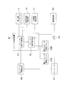
- FIG. 1 is a block diagram showing an elevator apparatus according to Embodiment 1 of the present invention.
- a hoisting machine 1 is provided in a hoistway of a building.
- the hoisting machine 1 has a motor 2 as a driving device and a sheave 3.
- the sheave 3 is rotated by the motor 2.
- the sheave 3 is provided with a hoisting machine encoder 4 as car speed detecting means.
- the hoisting machine encoder 4 generates an electrical signal corresponding to the rotation of the sheave 3.
- the main rope 5 is wound around the sheave 3.
- a car 6 and a counterweight 7 are suspended from the main rope 5.
- the sheave 3 is rotated by the driving force of the motor 2. Further, a frictional force is generated at a contact portion between the sheave 3 and the main rope 5. With this frictional force, the main rope 5 is moved as the sheave 3 rotates.
- the car 6 and the counterweight 7 are raised and lowered in the hoistway. That is, the car 6 and the counterweight 7 are raised and lowered by the driving force of the motor 2.
- a landing door device (not shown) as an elevator door device is provided at the landing on each floor of the building.
- a landing door opening / closing detector (not shown) as a door opening / closing state detecting means is attached to the landing door device.
- the landing door open / close detector generates a signal corresponding to the open / closed state of the landing door device.
- landing plates 8A and 8B are provided along the vertical direction at positions corresponding to the landing floors on the inner wall of the hoistway.
- the car 6 is provided with a car door device (not shown) as an elevator door device that opens and closes the entrance of the car 6. Further, the car 6 is provided with a scale device 9, an acceleration detector 10, a car door open / close detector 11 as door open / closed state detecting means, and a landing position detector 12 as car position detecting means. ing.
- the scale device 9 generates a signal corresponding to the loaded weight of the car 6.
- the acceleration detector 10 generates a signal corresponding to the vertical acceleration of the car 6.
- the car door open / close detector 11 generates a signal corresponding to the open / close state of the car door device.
- the landing position detector 12 is disposed on the outer surface of the car 6 at a position corresponding to the landing plates 8A and 8B. The landing position detector 12 generates an electrical signal by contacting or approaching the landing plates 8A and 8B.
- a governor unit 13 is provided in the hoistway.
- the governor unit 13 includes an emergency stop device (not shown), a first tension wheel 14A in which a governor body is incorporated, a second tension wheel 14B, and a governor rope 15. .
- the emergency stop device is provided in the car 6.
- the first tension wheel 14A and the second tension wheel 14B are provided at the upper and lower parts of the hoistway, respectively.
- the governor rope 15 is stretched endlessly between the first tension wheel 14A and the second tension wheel 14B. A part of the governor rope 15 is connected to an emergency stop device for the car 6.
- the first tension wheel 14 ⁇ / b> A and the second tension wheel 14 ⁇ / b> B are rotated by the movement of the governor rope 15 as the car 6 moves up and down.
- the governor body of the first tension wheel 14A can mechanically detect that the ascending / descending speed of the car 6 has reached a predetermined overspeed. Further, when the governor body detects that the ascending / descending speed of the car 6 has reached a predetermined overspeed, for example, the emergency stop mechanism of the car 6 is operated via the governor rope 15, and the car 6 Stop lifting.
- a governor encoder 16 is attached to the first tension wheel 14A. The governor encoder 16 generates an electrical signal corresponding to the rotational speed of the first tension wheel 14A.
- Brake device 20 is attached to hoisting machine 1.
- the brake device 20 includes a brake wheel 21, a first brake lining 22A, a second brake lining 22B, a first spring (not shown), a second spring (not shown), a first brake electromagnetic coil 23A, and a second brake. It has an electromagnetic coil 23B.
- the brake wheel 21 is attached to the rotating shaft of the motor 2. Further, the brake wheel 21 is rotated together with the sheave 3.
- the first brake lining 22A and the second brake lining 22B can be displaced between the braking position and the release position, respectively.
- the braking position is a position where the first brake lining 22A and the second brake lining 22B come into contact with the braking surface (for example, the outer peripheral surface) of the brake wheel 21.
- the open position is a position where the first brake lining 22A and the second brake lining 22B are spaced apart from the braking surface of the brake wheel 21. That is, the open position is a position where the first brake lining 22A and the second brake lining 22B are in a non-contact state with the braking surface of the brake wheel 21.
- the first brake lining 22A and the second brake lining 22B are urged toward the braking surface of the brake wheel 21 by the first spring and the second spring, respectively. Accordingly, the first brake lining 22 ⁇ / b> A and the second brake lining 22 ⁇ / b> B are pressed against the braking surface of the rotating brake wheel 21 by the first spring and the second spring, thereby causing friction between the first braking lining 22 ⁇ / b> A and the second brake lining 22 ⁇ / b> B. Power is generated. This frictional force brakes the rotation of the brake wheel 21, that is, the rotation of the motor 2.
- the first brake lining 22A and the second brake lining 22B are opened against the urging forces of the first spring and the second spring by the electromagnetic force of the first brake electromagnetic coil 23A and the second brake electromagnetic coil 23B, respectively. Displaced to position. Excitation / demagnetization of the first brake electromagnetic coil 23A and the second brake electromagnetic coil 23B is controlled by a brake control device 50 as a brake control unit.
- FIG. 2 is a block diagram showing a control system of the elevator apparatus of FIG.
- raising and lowering of the car 6 and the counterweight 7 are controlled by an elevator control device 60 as an operation control unit.
- the elevator control device 60 controls the driving of the motor 2 of the hoisting machine 1 via an inverter 61 for driving the hoisting machine.
- the inverter 61 is connected to the power supply device 62.
- a power cutoff switch (winding machine drive power cutoff switch) 63 is provided on the power line of the inverter 61. When the power cut-off switch 63 is opened, power supply to the inverter 61 is cut off.
- the brake control device 50 includes a brake operation determination unit 51 and a brake operation command unit 52.
- the brake operation determination unit 51 receives an operation command related to the brake operation from the elevator control device 60.
- the brake operation determination unit 51 receives electrical signals from the landing door open / close detector, the hoisting machine encoder 4, the car door open / close detector 11, and the landing position detector 12.
- the brake operation determination unit 51 determines the operation of the brake device 20 based on signals input from the devices 60, 4, 11, and 12 (including the landing door open / close detector). Further, the brake operation determination unit 51 sends an operation command corresponding to the determined operation of the brake device 20 to the brake operation command unit 52.
- the brake operation determining unit 51 holds the car 6 in a stationary state when the car 6 stops at the landing position.
- An operation command for causing the brake device 20 to exert the braking force for use is sent to the brake operation command unit 52.
- the brake operation determination unit 51 sends an operation command for releasing the stationary holding braking force of the brake device 20 to the brake operation command unit 52.
- the brake operation determination unit 51 monitors the traveling speed of the car 6 using the electric signal from the hoisting machine encoder 4. Furthermore, the brake operation determination unit 51 monitors the door open / close state of the car 6 using an electric signal from the car door open / close detector 11. Further, the brake operation determination unit 51 monitors the position of the car 6 using an electric signal from the landing position detector 12.
- the brake operation determination unit 51 confirms the success or failure of the door opening condition, the car position condition, and the car speed condition.
- the door opening condition is a condition that is satisfied when at least one of the car door device and the landing door device (that is, the elevator door device) is in an open state.
- the car position condition is a condition that is satisfied when the car position that is the height position of the car 6 is outside a predetermined door opening range (for example, outside the range of the landing plates 8A and 8B).
- the car speed condition is a condition that is satisfied when the car speed that is the traveling speed of the car 6 is equal to or higher than a predetermined speed (for example, a speed that is about half the rated speed of the car 6).
- the brake operation command unit 52 is configured to apply an excitation current to the first brake electromagnetic coil 23A and the second brake electromagnetic coil 23B based on the operation command from the brake operation determination unit 51, that is, according to the determination of the brake operation determination unit 51. Controls the interruption and the amount of current. In addition, the brake operation command unit 52 exerts a normal stop braking force on the brake device 20 for stopping the car 6 based on the operation command from the brake operation determination unit 51 when the raising / lowering of the car 6 is stopped.
- the brake operation command unit 52 gradually stops the car 6 that is being lifted and lowered based on the operation command from the brake operation determination unit 51 (decelerate the car 6 relatively slowly).
- the braking device 20 exerts either one of the braking force for slowing down for stopping the vehicle 6 and the braking force for suddenly stopping the car 6 that is moving up and down.
- the brake operation command unit 52 blocks the excitation current to the first brake electromagnetic coil 23A and the second brake electromagnetic coil 23B when the brake device 20 exerts the braking force for sudden stop and the braking force for stationary holding. To do. As a result, the brake device 20 exhibits a maximum braking force determined by the spring force of the first spring and the second spring.
- the brake operation command unit 52 causes the brake device 20 to exhibit the braking force for slowing down
- the current amount of the excitation current to the first brake electromagnetic coil 23A and the second brake electromagnetic coil 23B is It is made smaller than when the brake device 20 is opened. Accordingly, the brake device 20 exhibits an intermediate braking force that is a braking force smaller than the maximum braking force.
- the brake operation command unit 52 controls the opening / closing of the power cutoff switch 63. Further, the brake operation command unit 52 closes the power cut-off switch 63 during the normal operation of the car 6. Further, the brake operation command unit 52 opens the power shut-off switch 63 in order to forcibly stop the driving of the hoisting machine 1 when the brake device 20 exerts the braking force for sudden stop. The power supply of 61 is cut off.
- the brake operation determination unit 51 suddenly stops when it is confirmed that at least one of the car position condition and the car speed condition is satisfied.
- An operation command for causing the brake device 20 to exert the braking force for use is sent to the brake operation command unit 52.
- the brake operation command unit 52 causes the brake device 20 to exert the sudden stop braking force based on the command from the brake operation determination unit 51.
- the brake control device 50 can be configured by hardware (not shown) having an arithmetic processing unit (CPU), a storage unit (ROM, RAM, hard disk, etc.) and a signal input / output unit.
- the hardware storage unit of the brake control device 50 stores a program for realizing the functions of the brake operation determination unit 51 and the brake operation command unit 52.
- the elevator control device 60 can also be configured by hardware (not shown).
- a program for realizing the function of the elevator control device 60 is stored in the hardware storage unit of the elevator control device 60.
- the brake control device 50 determines whether the door opening condition is satisfied based only on the open / closed state of the car door device.
- the brake control device 50 determines whether the door opening condition is satisfied based on the opening / closing state of the landing door device, the same handling as described below is possible (the same applies to the third and fourth embodiments). .
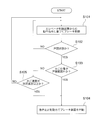
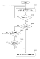
- FIG. 3 is a flowchart showing the operation of the brake control device 50 of FIG.
- the brake control device 50 performs brake control based on an operation command from the elevator control device 60 when the car 6 is in the door-closed state (step S ⁇ b> 101), and whether the car 6 is in the door-open state. (Success / failure of the door opening condition) is monitored (step S102).
- the brake control device 50 confirms that the car 6 is in the door open state (satisfaction of the door open condition) (YES direction in step S102), whether or not the car position is out of the door open range.
- Step S103 Confirmation of success or failure of the car position condition).
- the brake control device 50 confirms that the car position is outside the door opening range (satisfaction of the car position condition)
- the brake device 20 is operated with the braking force for sudden stop (step S104).
- the brake control device 50 opens the power cut-off switch 63 to cut off the power supply to the hoist 1. Thereafter, the brake control device 50 waits until a reset operation by the worker is received or the restoration operation by the elevator control device 60 ends.
- step S105 Confirmation of success or failure of car speed conditions.
- the brake control device 50 operates the brake device 20 with the braking force for sudden stop (step S104).
- the brake control device 50 opens the power cut-off switch 63 to cut off the power supply to the hoist 1. Thereafter, the brake control device 50 waits until a reset operation by the worker is received or the restoration operation by the elevator control device 60 ends.
- step S105 when the brake control device 50 confirms that the car speed is less than the predetermined speed (in step S105) (the car speed condition is not satisfied), the brake control device 50 performs brake control based on the operation command from the elevator control device 60. (Step S101), the same operation is repeated.
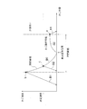
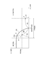
- FIG. 4 is an explanatory diagram for explaining changes in the car speed and the car position.
- the control panel drop prevention means determines whether or not the rope clipper is operated by checking whether the car position is outside the door opening range when the car is open. . And in the conventional elevator apparatus, when the car position exceeds the door opening range (point a in FIG. 4) during, for example, floor-to-floor operation, as shown by arrows A0 and A1 in FIG. The lift of the car is suddenly stopped by the rope clipper.
- the brake control device 50 confirms that either the car speed condition or the car position condition is satisfied after confirming that the door opening condition is satisfied.
- the elevator 6 is suddenly stopped. That is, when it is confirmed that both the door opening condition and the car position condition are satisfied, the brake control device 50, as shown in the arrows A0 and A1 in FIG. suddenly stop lifting 6
- the brake control device 50 confirms that both the door opening condition and the car speed condition are satisfied, that is, when the car speed becomes equal to or higher than the predetermined speed in the arrow B0 in FIG. 4 (point c in FIG. 4). ), As shown by arrow B2, the raising and lowering of the car 6 is suddenly stopped. As a result, the decelerating shock given to the user in the car 6 can be mitigated as compared with the conventional elevator apparatus, because the continuous deceleration state becomes a relatively short time.
- the car speed cannot be made much lower than the predetermined speed, so the car 6 can be stopped at a location relatively close to the door opening range. Therefore, in the elevator apparatus of the first embodiment, the car being opened without using the rope clipper in the conventional elevator apparatus as shown in Patent Document 1 and without further increasing the maximum braking force of the brake apparatus 20. 6 unexpected operations can be dealt with. That is, without using a relatively high-performance brake lining, a brake device with improved responsiveness for immediate operation, a rope clipper provided in a hoistway (machine room) separately from the brake device 20, etc. Unexpected operation of the opened car 6 can be dealt with, and the manufacturing cost can be reduced.
- the brake control device 50 does not perform an emergency stop unless the car position condition is satisfied. Thereby, the emergency stop of the raising / lowering of the cage
- Embodiment 2 In general, in an elevator apparatus, relatively high operational reliability is required for each sensor and the brake control device 50 in order to ensure higher safety. Therefore, in the elevator apparatus of the second embodiment, the sensors (the hoisting machine encoder 4, the car door opening / closing detector 11 and the landing position detector 12) in the first embodiment are made redundant (multiplexed). Yes.
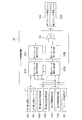
- FIG. 5 is a block diagram showing a part of an elevator apparatus according to Embodiment 2 of the present invention.
- the first hoisting machine encoder 4A and the second hoisting machine encoder 4B are used as the hoisting machine encoder 4 in the first embodiment.
- a first door opening / closing detector 11A and a second door opening / closing detector 11B are used as the car door opening / closing detector 11 in the first embodiment.
- the first landing position detector 12A and the second landing position detector 12B are used as the landing position detector 12 in the first embodiment.
- the functions of these sensors 4A, 4B, 11A, 11B, 12A, and 12B are the same as the functions of the devices 4, 11, and 12 of the first embodiment.
- the brake control device 50 of the second embodiment includes a first brake operation determination unit 51A and a second brake operation determination unit 51B as the brake operation determination unit 51 in the first embodiment. Furthermore, the brake control device 50 includes a first brake operation command unit 52A and a second brake operation command unit 52B as the brake operation command unit 52 in the first embodiment. The brake control device 50 further includes an OR operation unit 53.
- the first brake operation determination unit 51A and the second brake operation determination unit 51B receive signals from the elevator control device 60 and each of the sensors 4A, 4B, 11A, 11B, 12A, and 12B. Further, the first brake operation determination unit 51A and the second brake operation determination unit 51B confirm whether or not the same type of signals among the sensors 4A, 4B, 11A, 11B, 12A, and 12B match.
- the first brake operation determination unit 51A and the second brake operation determination unit 51B have one of the sensors 4A, 4B, 11A, 11B, 12A, and 12B out of order. Judgment that there is a possibility, emergency stop and service stop, to ensure safety.
- the first brake operation determination unit 51A and the second brake operation determination unit 51B compare the calculation results with each other, and perform the same processing on the signals of the sensors 4A, 4B, 11A, 11B, 12A, and 12B. Check whether the results match. If these results are different, the first brake operation determination unit 51A and the second brake operation determination unit 51B may have a failure in one of the brake operation determination units 51A and 51B including itself. It is determined that there is an emergency stop and service is stopped to ensure safety.
- the calculation results of the first brake operation command unit 52A and the second brake operation command unit 52B are sent to the OR calculation unit 53, and the OR calculation unit 53 calculates the logical sum of the brake operations. That is, even if one of the first brake operation command unit 52A and the second brake operation command unit 52B fails, the brake device 20 is activated to ensure safety if the other one operates. It has a configuration that can.
- different hardware may be used for each of the first brake operation determination unit 51A and the second brake operation determination unit 51B.
- different hardware may be used for the first brake operation command unit 52A and the second brake operation command unit 52B.
- Other functions of the brake control device 50 of the second embodiment and other configurations and operations of the elevator device of the second embodiment are the same as those of the first embodiment.
- the first brake operation determination unit 51A and the second brake operation determination unit 51B, the first brake operation command unit 52A and the second brake operation command unit 52B, Sensors 4A, 4B, 11A, 11B, 12A, and 12B are made redundant (multiplexed). With this configuration, it is possible to detect the occurrence of abnormality in each of the sensors 4A, 4B, 11A, 11B, 12A, and 12B independently from the elevator control device 60, and to further improve the safety and reliability against failure of each device. Can be improved.
- the first brake operation determination unit 51A and the second brake operation determination unit 51B, the first brake operation command unit 52A and the second brake operation command unit 52B, and the sensors 4A, 4B, and 11A. , 11B, 12A, and 12B are doubled.
- the present invention is not limited to this example, and these devices and functions may have a configuration of triple or more.
- the landing door open / close detector may be made redundant.
- Embodiment 3 the elevator system adopts a high-speed door opening method that opens the car door device relatively quickly, shortening the time until the user can get on and off, and improving the operation efficiency.
- One of the high-speed door opening methods is a landing door opening method in which the opening of the car door device is started before the car has completely reached the floor position. The relationship between the car speed and the car position when the brake control system of the brake control apparatus 50 according to the first embodiment is applied to an elevator apparatus to which such a landing front door opening system is applied will be described with reference to FIG. To do.
- FIG. 6 is an explanatory diagram for explaining changes in the car speed and the car position when the respective brake control devices 50 of the first embodiment and the third embodiment of the present invention are applied.
- FIG. 6 the change in the car speed and the car position when the brake control method of the brake control device 50 of the first embodiment is applied to an elevator device to which the landing front door opening method is applied is shown in FIG. Expressed as driving.
- the brake control device 50 confirms whether or not the car speed increase condition is satisfied instead of the car speed condition according to the first embodiment. Then, when it is confirmed that both the door opening condition and the car speed increasing condition are satisfied, the brake control device 50 causes the brake device 20 to exert a sudden stopping braking force.
- the car speed increase condition is a condition that is satisfied when the car position is within the door opening range and the car speed increases from less than a predetermined speed to a predetermined speed or more (when it reaches). Further, when the car speed increase condition is satisfied, the car speed increase condition is not satisfied in response to the car position being displaced from the door opening range to the outside of the door opening range.
- the elevator apparatus of Embodiment 3 even if the car door apparatus starts to open at a certain point (point d) before the stop when the car 6 enters the door opening range, the right side of the point d in the arrow C0. As described above, the raising / lowering of the car 6 is not emergency stopped. Note that the brake control device 50 stores information on changes in the car speed and the car position in chronological order so that the past operation of the car 6 can be confirmed.
- Other configurations of the elevator apparatus according to the third embodiment are the same as at least one of the first and second embodiments.
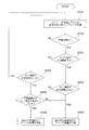
- FIG. 7 is a flowchart showing the operation of the brake control device 50 according to Embodiment 3 of the present invention.
- the operation after confirming that the car position is within the door opening range among the operations of the brake control device 50 of the first embodiment is different.
- the operation after step S103 in the NO direction is different.
- the operations of the brake control device 50 of the third embodiment only differences from the first embodiment will be described.
- step S205 when the brake control device 50 confirms that the car position is within the door opening range (NO direction in step S103), the brake control device 50 checks whether the car speed is equal to or higher than a predetermined speed (step S205). At this time, when the brake control device 50 confirms that the car speed is equal to or higher than the predetermined speed, the door opening range (the door opening range corresponding to the current car position among the door opening ranges on each floor). It is confirmed whether or not the car speed has increased from below the predetermined speed to above the predetermined speed (step S206: confirmation of success or failure of the car speed increasing condition).
- the brake control device 50 When the brake control device 50 confirms that the car speed has increased from less than the predetermined speed to more than the predetermined speed within the door opening range (satisfaction of the car speed increase condition), the brake control device 50 controls the sudden stop.
- the brake device 20 is operated with power (step S104).
- the brake control device 50 opens the power cut-off switch 63 to cut off the power supply to the hoist 1. Thereafter, the brake control device 50 waits until a reset operation by the worker is received or the restoration operation by the elevator control device 60 ends.
- step S206 brake control based on the operation command from the elevator control device 60 is performed without causing the braking device 20 to exert the braking force for sudden stop (step S101), and the same operation is repeated.
- Other operations of the brake control device 50 of the third embodiment are the same as the operations of the brake control device 50 of the first embodiment.
- the brake control device 50 when the brake control device 50 confirms that both the car position condition and the car speed increase condition and the door opening condition are satisfied.
- the braking device 20 is caused to exert the emergency stop braking force. Accordingly, if the car position is within the door opening range when the door opening condition is satisfied, and the car speed increasing condition is not satisfied, the brake control device 50 will not stop the car even if the car speed is equal to or higher than the predetermined speed. 6. Elevating 6 is not emergency stopped. As a result, when the door opening method before landing is adopted, it is possible to avoid unnecessary emergency stop of the raising / lowering of the car 6 and to obtain the same effect as in the first embodiment.
- Embodiment 4 FIG. In general, during an emergency stop such as a power failure, the elevator apparatus stops the car relatively gently in order to further reduce the deceleration shock while performing various safety judgments. In particular, when the vehicle is decelerated and stopped with a relatively high braking force from a relatively high speed, a relatively high deceleration state continues, and the burden on the passenger due to the deceleration shock increases.
- the elevator apparatus when at least one of the car door device and the landing door device is in an open state while the car is moving up and down, the elevator apparatus generally performs an emergency stop of the car ascending and descending. Even in this case, it is necessary to apply to the elevator device an emergency speed reduction method that reduces the shock so that the stop distance is not unnecessarily increased while further reducing the deceleration shock.
- the relationship between the car speed and the car position when the brake control system of the brake control device 50 according to the third embodiment is applied to an elevator apparatus to which such an emergency deceleration system is applied will be described with reference to FIG.
- FIG. 8 is an explanatory diagram for explaining a change in the car speed and the car position when the brake control devices 50 of the third embodiment and the fourth embodiment of the present invention are applied.
- the change in the car speed and the car position when the brake control method of the brake control device 50 of the third embodiment is applied to an elevator device to which the emergency deceleration method is applied is represented as a normal operation of arrow D1. To do.
- the car speed during normal operation is higher than the predetermined speed, and when the door is opened at a certain position (point e in FIG. 8), the car 6 is slowly decelerated.
- the brake control system of the brake control device 50 according to the third embodiment when the car 6 is decelerating and the car position exceeds the door opening range, the door opening condition and the car position condition are set. Therefore, when the door opening range is exceeded (point f in FIG. 8), the raising / lowering of the car 6 suddenly stops as indicated by the arrow D2, and the deceleration shock becomes relatively large.
- the brake control apparatus 50 confirms whether or not the car speed increase condition is satisfied when it is confirmed that both the door opening condition and the car speed condition are satisfied.
- the brake control device 50 confirms that the car speed increase condition is not satisfied, the brake control device 50 causes the brake device 20 to exert a braking force for slowing stop so as to slowly stop the raising and lowering of the car 6.
- the brake control device 50 causes the brake device 20 to exert a braking force for sudden stop, and suddenly stops the raising and lowering of the car 6.
- the brake control device 50 causes the braking device 20 to exert the braking force for slowing down, even if it is confirmed that both the door opening condition and the car position condition are satisfied, the arrow in FIG. As shown on the right side of the point f of D3, the brake device 20 continues to exert the braking force for slowing down. Therefore, the car 6 is decelerated relatively slowly by the braking force for slowing down the brake device 20 as indicated by an arrow D3.
- the brake control device 50 causes the brake device 20 to exert the braking force for sudden stop when confirming that all of the door opening condition, the car speed condition, and the car speed increasing condition are satisfied.
- the brake control device 50 causes the braking device 20 to exert a braking force for slowing down.
- the brake control device 50 causes the brake device 20 to exert the braking force for slowing down when confirming that the door opening condition, the car position condition, and the car speed condition are all satisfied.
- the brake control device 50 causes the brake device 20 to exert a sudden stopping braking force when it is confirmed that both the door opening condition and the car position condition are satisfied and the car speed condition is not satisfied.
- the brake control device 50 stores information on changes in the car speed and the car position in chronological order as in the third embodiment, so that the past operation of the car 6 can be confirmed. ing.
- Other configurations of the elevator apparatus of the fourth embodiment are the same as those of the third embodiment.
- FIG. 9 is a flowchart showing the operation of the brake control device 50 according to Embodiment 4 of the present invention.
- the brake control device 50 performs brake control based on the operation command from the elevator control device 60 (step S101), and whether the car 6 is in the door-open state. (Step S102: Confirmation of success or failure of the door opening condition).
- Step S301 Confirmation of success or failure of the car position condition.
- the brake control device 50 checks whether the car speed is equal to or higher than a predetermined speed (step).
- S302 Confirmation of success or failure of the car speed condition).
- the brake control device 50 operates the brake device 20 with the braking force for slowing down (step S303).
- Step S304 when it is confirmed that the car speed is less than the predetermined speed (the car speed condition is not satisfied) (NO direction in step S302), the brake control device 50 operates the brake device 20 with the braking force for sudden stop. (Step S304).
- Step S305 Confirmation of success or failure of the car speed condition.
- step S305 when the brake control device 50 confirms that the car speed is less than the predetermined speed (the car speed condition is not satisfied) (NO direction in step S305), the brake control device 50 does not operate the brake device 20 and does not operate the elevator. Brake control is performed based on the operation command from the control device 60 (step S101), and the same operation is repeated.
- step S305 when the brake control device 50 confirms that the car speed is abnormal at a predetermined speed (the car speed condition is satisfied) (YES direction in step S305), the car speed is less than the predetermined speed within the door opening range. It is confirmed whether or not the vehicle speed has increased to a predetermined speed or higher (step S306: confirmation of success or failure of the car speed increase condition).
- step S304 When the brake control device 50 confirms that the car speed has increased from less than the predetermined speed to more than the predetermined speed within the door opening range (satisfaction of the car speed increase condition) (YES direction in step S306) ), The brake device 20 is operated with the braking force for sudden stop (step S304).
- step S306 when the brake control device 50 confirms that the car speed has increased from less than the predetermined speed to more than the predetermined speed outside the door opening range (car speed increase condition is not satisfied) (NO direction of step S306) ), The brake device 20 is operated with the braking force for slowing down (step S303).
- the brake control device 50 sets the power shut-off switch 63 to the open state when operating the brake device 20 with the braking force for slow stop or the braking force for sudden stop.
- the power supply to the hoisting machine 1 is cut off. Thereafter, the brake control device 50 waits until a reset operation by the worker is received or the restoration operation by the elevator control device 60 ends.
- the brake control device 50 confirms that both the door opening condition and the car speed condition are satisfied and the car speed increasing condition is not satisfied, or the door opening condition.
- the braking device 20 exerts the braking force for slowing down.
- the car position and car speed state detected in chronological order may be stored in a plurality of storage units. That is, the hardware storage unit of the brake control device 50 may be made redundant. Thereby, the brake control apparatus 50 can detect operation
- the car position and the past state of the car speed detected in chronological order are not stored, but the car position is used using the information stored in the elevator control device 60. And the past state of the car speed may be confirmed.
- the hoisting machine encoders 4, 4A, 4B are used as the car speed detecting means in order to detect the speed of the car 6.
- the present invention is not limited to this example.
- the brake controller 50 detects the car speed by using other sensors such as the governor encoder 16 and the acceleration detector 10 as the car speed detecting means.
- the brake control device 50 detects the car position by using other sensors such as the hoisting machine encoder 4, the governor encoder 16, and the acceleration detector 10 as car position detecting means. Also good.
- the brake speed can be obtained simultaneously by the brake control device 50 performing differential processing on the signal.
- Embodiments 1 to 4 in order not to cause an emergency stop in the floor-to-floor operation of the car 6, it is necessary to set a speed that cannot occur during the floor-to-floor operation as a predetermined speed.
- an elevator apparatus that does not have a floor matching function may be set to a lower speed (for example, a speed lower than half of the rated speed) as compared with the predetermined speed in the first to fourth embodiments.
- positions that are separated from the door opening reference position by a predetermined distance above and below are set as boundary positions (upper limit position and lower limit position) of the door opening range.
- the maximum allowable distance that is the maximum distance that the car in the door open state can move away from the landing reference position is the boundary between the car position and the door opening range.
- the predetermined distance from the door opening reference position (that is, the door opening range) is: It can be determined by the relationship between the predetermined speed and the braking force for sudden stop.
Landscapes
- Engineering & Computer Science (AREA)
- Automation & Control Theory (AREA)
- Maintenance And Inspection Apparatuses For Elevators (AREA)
- Indicating And Signalling Devices For Elevators (AREA)
- Elevator Control (AREA)
Abstract
Description
実施の形態1.
図1は、この発明の実施の形態1によるエレベータ装置を示す構成図である。
図1において、建物の昇降路には、巻上機1が設けられている。巻上機1は、駆動装置としてのモータ2と、シーブ3とを有している。シーブ3は、モータ2により回転される。シーブ3には、かご速度検出手段としての巻上機エンコーダ4が取り付けられている。巻上機エンコーダ4は、シーブ3の回転に応じた電気信号を生成する。
一般的に、エレベータ装置においては、より高い安全性を確保するために、各センサ類及びブレーキ制御装置50について、比較的高い動作信頼性が要求される。そこで、実施の形態2のエレベータ装置では、実施の形態1における各センサ類(巻上機エンコーダ4、かご用戸開閉検出器11及び着床位置検出器12)が冗長化(多重化)されている。
まず、一般的に、エレベータ装置は、かごドア装置を比較的に早く開放する高速戸開方式を採用し、利用者の乗り降りが可能となるまでの時間を短縮し、運行効率を向上させている。この高速戸開方式の一つには、かごの走行が完全に床位置に到着する前に、かごドア装置の開放を開始する着床前戸開方式がある。このような着床前戸開方式を適用したエレベータ装置に、実施の形態1のブレーキ制御装置50のブレーキ制御方式を適用した場合のかご速度とかご位置との関係について、図6を用いて説明する。
一般的に、エレベータ装置は、例えば停電等の非常停止時においては、種々の安全判断を実施しながら減速ショックをより緩和するために、比較的緩やかにかごを停止させる。特に、比較的高い速度から、比較的高い制動力で減速停止すると、連続して比較的高い減速度状態が続くこととなり、乗客への減速ショックによる負担は大きくなる。
Claims (4)
- 昇降路内を昇降されるかごと、
前記かごの出入口を含むエレベータ出入口を開閉するエレベータドア装置と、
前記かごの昇降を駆動する駆動装置と、
前記かごの昇降を制動するブレーキ装置と、
前記かごの運転を制御する運転制御部と、
前記かごの位置に応じた信号を生成するかご位置検出手段と、
前記かごの走行速度に応じた信号を生成するかご速度検出手段と、
前記エレベータドア装置の開閉状態に応じた信号を生成する戸開閉状態検出手段と、
前記運転制御部からの指令に基づいて前記ブレーキ装置の動作を制御するブレーキ制御部と
を備えるエレベータ装置であって、
前記ブレーキ制御部は、前記かご位置検出手段、前記かご速度検出手段及び前記戸開閉状態検出手段を介して、前記かごの位置、前記かごの走行速度、及び前記エレベータドア装置の開閉状態を監視し、
前記エレベータドア装置が開放状態のときに成立する戸開条件と、
前記かごの位置が所定の戸開範囲外のときに成立するかご位置条件と、
前記かごの走行速度が所定速度以上のときに成立するかご速度条件と
のそれぞれの成否を確認し、前記かご位置条件及び前記かご速度条件の少なくともいずれか一方の条件と、前記戸開条件との両方の成立を確認した際に、昇降中の前記かごを急停止させるための急停止用制動力を前記ブレーキ装置に発揮させるエレベータ装置。 - 昇降路内を昇降されるかごと、
前記かごの出入口を含むエレベータ出入口を開閉するエレベータドア装置と、
前記かごの昇降を駆動する駆動装置と、
前記かごの昇降を制動するブレーキ装置と、
前記かごの運転を制御する運転制御部と、
前記かごの位置に応じた信号を生成するかご位置検出手段と、
前記かごの走行速度に応じた信号を生成するかご速度検出手段と、
前記エレベータドア装置の開閉状態に応じた信号を生成する戸開閉状態検出手段と、
前記運転制御部からの指令に基づいて前記ブレーキ装置の動作を制御するブレーキ制御部と
を備えるエレベータ装置であって、
前記ブレーキ制御部は、前記かご位置検出手段、前記かご速度検出手段及び前記戸開閉状態検出手段を介して、前記かごの位置、前記かごの走行速度、及び前記エレベータドア装置の開閉状態を監視し、
前記エレベータドア装置が開放状態のときに成立する戸開条件と、
前記かごの位置が所定の戸開範囲外のときに成立するかご位置条件と、
前記かごの位置が所定の戸開範囲内のときで、かつ前記かごの走行速度が所定速度未満から前記所定速度以上に変化したときに成立するかご速度増加条件と
のそれぞれの成否を確認し、前記かご位置条件及び前記かご速度増加条件の少なくともいずれか一方の条件と、前記戸開条件との両方の成立を確認した際に、昇降中の前記かごを急停止させるための急停止用制動力を前記ブレーキ装置に発揮させるエレベータ装置。 - 前記ブレーキ制御部は、前記かごの走行速度が所定速度以上のときに成立するかご速度条件の成否をさらに確認し、
前記かご速度条件と前記戸開条件との両方の成立を確認した際には、その際に、
前記かご速度増加条件の成立を確認した場合に、前記急停止用制動力を前記ブレーキ装置に発揮させ、
前記かご速度増加条件の不成立を確認した場合に、前記かごを徐行停止させるための徐行停止用制動力を前記ブレーキ装置に発揮させ、
前記かご位置条件と前記戸開条件との両方の成立を確認した際には、その際に、
前記かご速度条件の成立を確認した場合に、前記急停止用制動力に代えて、前記徐行停止用制動力を前記ブレーキ装置に発揮させ、
前記かご速度条件の不成立を確認した場合に、前記急停止用制動力を前記ブレーキ装置に発揮させる
請求項2記載のエレベータ装置。 - 前記ブレーキ制御部は、前記戸開条件、前記かご位置条件及び前記かご速度条件のそれぞれの成否を確認し前記ブレーキ装置の動作を決定するブレーキ動作判断部と、前記ブレーキ動作判断部の決定に従い前記ブレーキ装置を作動させるブレーキ操作指令部とを有しており、
前記かご速度検出手段と、前記戸開閉状態検出手段と、前記かご位置検出手段と、前記ブレーキ動作判断部と、前記ブレーキ操作指令部とは、それぞれ冗長化されている
請求項1記載のエレベータ装置。
Priority Applications (6)
| Application Number | Priority Date | Filing Date | Title |
|---|---|---|---|
| US13/376,643 US20120073909A1 (en) | 2009-06-22 | 2009-06-22 | Elevator device |
| EP09846474A EP2447201A1 (en) | 2009-06-22 | 2009-06-22 | Elevator device |
| PCT/JP2009/061333 WO2010150341A1 (ja) | 2009-06-22 | 2009-06-22 | エレベータ装置 |
| CN2009801600039A CN102459049A (zh) | 2009-06-22 | 2009-06-22 | 电梯装置 |
| KR1020117030154A KR20120023105A (ko) | 2009-06-22 | 2009-06-22 | 엘리베이터 장치 |
| JP2011519404A JPWO2010150341A1 (ja) | 2009-06-22 | 2009-06-22 | エレベータ装置 |
Applications Claiming Priority (1)
| Application Number | Priority Date | Filing Date | Title |
|---|---|---|---|
| PCT/JP2009/061333 WO2010150341A1 (ja) | 2009-06-22 | 2009-06-22 | エレベータ装置 |
Publications (1)
| Publication Number | Publication Date |
|---|---|
| WO2010150341A1 true WO2010150341A1 (ja) | 2010-12-29 |
Family
ID=43386137
Family Applications (1)
| Application Number | Title | Priority Date | Filing Date |
|---|---|---|---|
| PCT/JP2009/061333 Ceased WO2010150341A1 (ja) | 2009-06-22 | 2009-06-22 | エレベータ装置 |
Country Status (6)
| Country | Link |
|---|---|
| US (1) | US20120073909A1 (ja) |
| EP (1) | EP2447201A1 (ja) |
| JP (1) | JPWO2010150341A1 (ja) |
| KR (1) | KR20120023105A (ja) |
| CN (1) | CN102459049A (ja) |
| WO (1) | WO2010150341A1 (ja) |
Cited By (5)
| Publication number | Priority date | Publication date | Assignee | Title |
|---|---|---|---|---|
| CN104144868A (zh) * | 2011-10-18 | 2014-11-12 | 埃尔格电子两合公司 | 用于电梯箱的位置采集的装置和用于运行电梯设备的方法 |
| EP2681142A4 (en) * | 2011-02-28 | 2018-02-28 | Otis Elevator Company | Elevator car movement control in a landing zone |
| CN111332894A (zh) * | 2020-02-28 | 2020-06-26 | 深圳市通用互联科技有限责任公司 | 电梯故障检测方法、装置、计算机设备和存储介质 |
| JP2024067446A (ja) * | 2022-11-04 | 2024-05-17 | 株式会社Omcテクニカ | ロープ式エレベータの速度監視システム |
| JP7597263B1 (ja) * | 2024-03-25 | 2024-12-10 | フジテック株式会社 | 乗客コンベアのシャフトの異常検出装置及びエレベーター |
Families Citing this family (19)
| Publication number | Priority date | Publication date | Assignee | Title |
|---|---|---|---|---|
| KR20110016984A (ko) * | 2008-06-03 | 2011-02-18 | 오티스 엘리베이터 컴파니 | 엘리베이터들에 대한 (전기적) 단일 브레이크슈 테스트 |
| EP2361869A4 (en) * | 2008-12-11 | 2014-05-14 | Mitsubishi Electric Corp | ELEVATOR APPARATUS |
| US9637349B2 (en) | 2010-11-04 | 2017-05-02 | Otis Elevator Company | Elevator brake including coaxially aligned first and second brake members |
| DE102010052396A1 (de) * | 2010-11-24 | 2012-05-24 | Kuka Roboter Gmbh | Verfahren und Vorrichtung zum Steuern einer Peripheriekomponente eines Robotersystems |
| DE102010062154A1 (de) * | 2010-11-29 | 2012-05-31 | Thyssenkrupp Aufzugswerke Gmbh | Sicherheitseinrichtung für einen Aufzug |
| EP2594519A1 (de) * | 2011-11-15 | 2013-05-22 | Inventio AG | Aufzug mit Sicherheitseinrichtung |
| DE102012011539A1 (de) * | 2012-06-08 | 2013-12-12 | Siemag Tecberg Gmbh | Scheibenbremsanlage |
| FI125316B (fi) * | 2013-09-10 | 2015-08-31 | Kone Corp | Menetelmä hätäpysäytyksen suorittamiseksi sekä hissin turvajärjestely |
| EP3048074B1 (en) * | 2015-01-26 | 2022-01-05 | KONE Corporation | Method of eliminating a jerk arising by accelerating an elevator car |
| US10479645B2 (en) * | 2015-06-29 | 2019-11-19 | Otis Elevator Company | Electromagnetic brake system for elevator application |
| US10450162B2 (en) * | 2015-06-29 | 2019-10-22 | Otis Elevator Company | Electromagnetic brake control circuitry for elevator application |
| US10442659B2 (en) * | 2015-06-29 | 2019-10-15 | Otis Elevator Company | Electromagnetic brake system for elevator application |
| US10427908B2 (en) * | 2016-04-15 | 2019-10-01 | Otis Elevator Company | Emergency mode operation of elevator system having linear propulsion system |
| EP3336032B1 (en) * | 2016-12-14 | 2020-10-14 | Otis Elevator Company | Elevator safety system and method of operating an elevator system |
| EP3366626B1 (en) * | 2017-02-22 | 2021-01-06 | Otis Elevator Company | Elevator safety system and method of monitoring an elevator system |
| CN108217502B (zh) * | 2018-02-09 | 2024-01-12 | 广东亚太西奥电梯有限公司 | 一种电梯限速安控系统 |
| DE102018205633A1 (de) * | 2018-04-13 | 2019-10-17 | Thyssenkrupp Ag | Aufzugsanlage |
| DE102019212726A1 (de) * | 2019-08-26 | 2021-03-04 | Thyssenkrupp Elevator Innovation And Operations Ag | Aufzugsanlage die einen Fahrkorb abhängig von einem Schließzustandssignal und einer Position des Fahrkorbs in einen Sicherheitsbetriebszustand überführt |
| EP3878788B1 (en) * | 2020-03-09 | 2026-04-29 | Otis Elevator Company | Elevator safety systems |
Citations (3)
| Publication number | Priority date | Publication date | Assignee | Title |
|---|---|---|---|---|
| JPS5637980A (en) * | 1979-08-30 | 1981-04-11 | Mitsubishi Electric Corp | Safety device for elevator |
| JP2007055691A (ja) | 2005-08-22 | 2007-03-08 | Toshiba Elevator Co Ltd | エレベータ戸開発車防止装置 |
| WO2009008183A1 (ja) * | 2007-07-10 | 2009-01-15 | Mitsubishi Electric Corporation | エレベータ装置 |
Family Cites Families (13)
| Publication number | Priority date | Publication date | Assignee | Title |
|---|---|---|---|---|
| US4785914A (en) * | 1987-06-19 | 1988-11-22 | Westinghouse Electric Corp. | Elevator system leveling safeguard control and method |
| US5107964A (en) * | 1990-05-07 | 1992-04-28 | Otis Elevator Company | Separate elevator door chain |
| US5321216A (en) * | 1991-04-09 | 1994-06-14 | Otis Elevator Company | Restraining elevator car motion while the doors are open |
| FI118466B (fi) * | 2005-04-08 | 2007-11-30 | Kone Corp | Kunnonvalvontajärjestelmä |
| KR100931430B1 (ko) * | 2006-03-20 | 2009-12-11 | 미쓰비시덴키 가부시키가이샤 | 엘리베이터 장치 |
| CN101282899B (zh) * | 2006-07-27 | 2011-05-11 | 三菱电机株式会社 | 电梯装置 |
| FI119767B (fi) * | 2006-08-14 | 2009-03-13 | Kone Corp | Hissijärjestelmä ja menetelmä turvallisuuden varmistamiseksi hissijärjestelmässä |
| FI20070486A7 (fi) * | 2007-01-03 | 2008-07-04 | Kone Corp | Hissin turvajärjestely |
| ES2499340T3 (es) * | 2007-08-07 | 2014-09-29 | Thyssenkrupp Elevator Ag | Sistema de elevador |
| CN102317192B (zh) * | 2009-03-04 | 2013-09-04 | 三菱电机株式会社 | 电梯装置及其检查方法 |
| FI121065B (fi) * | 2009-03-05 | 2010-06-30 | Kone Corp | Hissijärjestelmä |
| DE102009037347A1 (de) * | 2009-08-14 | 2011-02-17 | K.A. Schmersal Holding Gmbh & Co. Kg | Elektronisches Sicherheitssystem für einen Aufzug |
| WO2011111223A1 (ja) * | 2010-03-12 | 2011-09-15 | 三菱電機株式会社 | エレベータ安全制御装置 |
-
2009
- 2009-06-22 EP EP09846474A patent/EP2447201A1/en not_active Withdrawn
- 2009-06-22 KR KR1020117030154A patent/KR20120023105A/ko not_active Ceased
- 2009-06-22 US US13/376,643 patent/US20120073909A1/en not_active Abandoned
- 2009-06-22 JP JP2011519404A patent/JPWO2010150341A1/ja active Pending
- 2009-06-22 CN CN2009801600039A patent/CN102459049A/zh active Pending
- 2009-06-22 WO PCT/JP2009/061333 patent/WO2010150341A1/ja not_active Ceased
Patent Citations (3)
| Publication number | Priority date | Publication date | Assignee | Title |
|---|---|---|---|---|
| JPS5637980A (en) * | 1979-08-30 | 1981-04-11 | Mitsubishi Electric Corp | Safety device for elevator |
| JP2007055691A (ja) | 2005-08-22 | 2007-03-08 | Toshiba Elevator Co Ltd | エレベータ戸開発車防止装置 |
| WO2009008183A1 (ja) * | 2007-07-10 | 2009-01-15 | Mitsubishi Electric Corporation | エレベータ装置 |
Cited By (7)
| Publication number | Priority date | Publication date | Assignee | Title |
|---|---|---|---|---|
| EP2681142A4 (en) * | 2011-02-28 | 2018-02-28 | Otis Elevator Company | Elevator car movement control in a landing zone |
| CN104144868A (zh) * | 2011-10-18 | 2014-11-12 | 埃尔格电子两合公司 | 用于电梯箱的位置采集的装置和用于运行电梯设备的方法 |
| US9776828B2 (en) | 2011-10-18 | 2017-10-03 | Elgo Electronic Gmbh & Co. Kg | Device for the position detection of an elevator car and method for operating an elevator system |
| CN111332894A (zh) * | 2020-02-28 | 2020-06-26 | 深圳市通用互联科技有限责任公司 | 电梯故障检测方法、装置、计算机设备和存储介质 |
| JP2024067446A (ja) * | 2022-11-04 | 2024-05-17 | 株式会社Omcテクニカ | ロープ式エレベータの速度監視システム |
| JP7543607B2 (ja) | 2022-11-04 | 2024-09-03 | 株式会社Omcテクニカ | ロープ式エレベータの速度監視システム |
| JP7597263B1 (ja) * | 2024-03-25 | 2024-12-10 | フジテック株式会社 | 乗客コンベアのシャフトの異常検出装置及びエレベーター |
Also Published As
| Publication number | Publication date |
|---|---|
| KR20120023105A (ko) | 2012-03-12 |
| US20120073909A1 (en) | 2012-03-29 |
| CN102459049A (zh) | 2012-05-16 |
| JPWO2010150341A1 (ja) | 2012-12-06 |
| EP2447201A1 (en) | 2012-05-02 |
Similar Documents
| Publication | Publication Date | Title |
|---|---|---|
| JPWO2010150341A1 (ja) | エレベータ装置 | |
| JP4987074B2 (ja) | エレベータ装置 | |
| CN101636340B (zh) | 电梯的制动装置 | |
| CN103189294B (zh) | 电梯装置 | |
| JP5726374B2 (ja) | エレベータ装置 | |
| CN1953926B (zh) | 电梯装置 | |
| JP5462836B2 (ja) | エレベーター用制動装置及びエレベーター | |
| JPWO2008062500A1 (ja) | エレベータ装置 | |
| JP2009526723A (ja) | エレベータブレーキ状態試験 | |
| CN102414110A (zh) | 电梯装置 | |
| CN103130065B (zh) | 电梯运行管理系统 | |
| WO2006027841A1 (ja) | エレベータ装置 | |
| JP5419936B2 (ja) | 災害対応型エレベータシステム | |
| JP2006298538A (ja) | エレベータ装置 | |
| EP3495302B1 (en) | Elevator apparatus and method | |
| CN101107191B (zh) | 电梯装置 | |
| WO2021176547A1 (ja) | エレベーターの安全制御システム、並びにそれを用いるエレベーター | |
| CN1993289B (zh) | 电梯用曳引装置 | |
| WO2008062509A1 (en) | Elevator controller | |
| JP5791490B2 (ja) | エレベータ非常停止装置およびエレベータ非常停止方法 | |
| JPWO2008068839A1 (ja) | エレベータ装置 | |
| JP6655489B2 (ja) | エレベーター | |
| JP7188590B2 (ja) | エレベーター装置 | |
| JP2015168487A (ja) | エレベーター装置及びその制御装置 | |
| JP5829869B2 (ja) | エレベータの非常停止装置 |
Legal Events
| Date | Code | Title | Description |
|---|---|---|---|
| WWE | Wipo information: entry into national phase |
Ref document number: 200980160003.9 Country of ref document: CN |
|
| 121 | Ep: the epo has been informed by wipo that ep was designated in this application |
Ref document number: 09846474 Country of ref document: EP Kind code of ref document: A1 |
|
| ENP | Entry into the national phase |
Ref document number: 2011519404 Country of ref document: JP Kind code of ref document: A |
|
| WWE | Wipo information: entry into national phase |
Ref document number: 13376643 Country of ref document: US |
|
| WWE | Wipo information: entry into national phase |
Ref document number: 2009846474 Country of ref document: EP |
|
| ENP | Entry into the national phase |
Ref document number: 20117030154 Country of ref document: KR Kind code of ref document: A |
|
| NENP | Non-entry into the national phase |
Ref country code: DE |