WO2010150567A1 - タービンロータ - Google Patents
タービンロータ Download PDFInfo
- Publication number
- WO2010150567A1 WO2010150567A1 PCT/JP2010/052266 JP2010052266W WO2010150567A1 WO 2010150567 A1 WO2010150567 A1 WO 2010150567A1 JP 2010052266 W JP2010052266 W JP 2010052266W WO 2010150567 A1 WO2010150567 A1 WO 2010150567A1
- Authority
- WO
- WIPO (PCT)
- Prior art keywords
- shroud
- line
- turbine rotor
- inlet
- outlet
- Prior art date
- Legal status (The legal status is an assumption and is not a legal conclusion. Google has not performed a legal analysis and makes no representation as to the accuracy of the status listed.)
- Ceased
Links
Images




Classifications
-
- F—MECHANICAL ENGINEERING; LIGHTING; HEATING; WEAPONS; BLASTING
- F01—MACHINES OR ENGINES IN GENERAL; ENGINE PLANTS IN GENERAL; STEAM ENGINES
- F01D—NON-POSITIVE DISPLACEMENT MACHINES OR ENGINES, e.g. STEAM TURBINES
- F01D5/00—Blades; Blade-carrying members; Heating, heat-insulating, cooling or antivibration means on the blades or the members
- F01D5/12—Blades
- F01D5/14—Form or construction
-
- F—MECHANICAL ENGINEERING; LIGHTING; HEATING; WEAPONS; BLASTING
- F01—MACHINES OR ENGINES IN GENERAL; ENGINE PLANTS IN GENERAL; STEAM ENGINES
- F01D—NON-POSITIVE DISPLACEMENT MACHINES OR ENGINES, e.g. STEAM TURBINES
- F01D5/00—Blades; Blade-carrying members; Heating, heat-insulating, cooling or antivibration means on the blades or the members
- F01D5/12—Blades
- F01D5/14—Form or construction
- F01D5/141—Shape, i.e. outer, aerodynamic form
-
- F—MECHANICAL ENGINEERING; LIGHTING; HEATING; WEAPONS; BLASTING
- F01—MACHINES OR ENGINES IN GENERAL; ENGINE PLANTS IN GENERAL; STEAM ENGINES
- F01D—NON-POSITIVE DISPLACEMENT MACHINES OR ENGINES, e.g. STEAM TURBINES
- F01D25/00—Component parts, details, or accessories, not provided for in, or of interest apart from, other groups
- F01D25/24—Casings; Casing parts, e.g. diaphragms, casing fastenings
-
- F—MECHANICAL ENGINEERING; LIGHTING; HEATING; WEAPONS; BLASTING
- F01—MACHINES OR ENGINES IN GENERAL; ENGINE PLANTS IN GENERAL; STEAM ENGINES
- F01D—NON-POSITIVE DISPLACEMENT MACHINES OR ENGINES, e.g. STEAM TURBINES
- F01D5/00—Blades; Blade-carrying members; Heating, heat-insulating, cooling or antivibration means on the blades or the members
- F01D5/02—Blade-carrying members, e.g. rotors
-
- F—MECHANICAL ENGINEERING; LIGHTING; HEATING; WEAPONS; BLASTING
- F01—MACHINES OR ENGINES IN GENERAL; ENGINE PLANTS IN GENERAL; STEAM ENGINES
- F01D—NON-POSITIVE DISPLACEMENT MACHINES OR ENGINES, e.g. STEAM TURBINES
- F01D5/00—Blades; Blade-carrying members; Heating, heat-insulating, cooling or antivibration means on the blades or the members
- F01D5/02—Blade-carrying members, e.g. rotors
- F01D5/04—Blade-carrying members, e.g. rotors for radial-flow machines or engines
-
- F—MECHANICAL ENGINEERING; LIGHTING; HEATING; WEAPONS; BLASTING
- F01—MACHINES OR ENGINES IN GENERAL; ENGINE PLANTS IN GENERAL; STEAM ENGINES
- F01D—NON-POSITIVE DISPLACEMENT MACHINES OR ENGINES, e.g. STEAM TURBINES
- F01D5/00—Blades; Blade-carrying members; Heating, heat-insulating, cooling or antivibration means on the blades or the members
- F01D5/02—Blade-carrying members, e.g. rotors
- F01D5/04—Blade-carrying members, e.g. rotors for radial-flow machines or engines
- F01D5/043—Blade-carrying members, e.g. rotors for radial-flow machines or engines of the axial inlet- radial outlet, or vice versa, type
-
- F—MECHANICAL ENGINEERING; LIGHTING; HEATING; WEAPONS; BLASTING
- F01—MACHINES OR ENGINES IN GENERAL; ENGINE PLANTS IN GENERAL; STEAM ENGINES
- F01D—NON-POSITIVE DISPLACEMENT MACHINES OR ENGINES, e.g. STEAM TURBINES
- F01D5/00—Blades; Blade-carrying members; Heating, heat-insulating, cooling or antivibration means on the blades or the members
- F01D5/02—Blade-carrying members, e.g. rotors
- F01D5/04—Blade-carrying members, e.g. rotors for radial-flow machines or engines
- F01D5/043—Blade-carrying members, e.g. rotors for radial-flow machines or engines of the axial inlet- radial outlet, or vice versa, type
- F01D5/048—Form or construction
-
- F—MECHANICAL ENGINEERING; LIGHTING; HEATING; WEAPONS; BLASTING
- F01—MACHINES OR ENGINES IN GENERAL; ENGINE PLANTS IN GENERAL; STEAM ENGINES
- F01D—NON-POSITIVE DISPLACEMENT MACHINES OR ENGINES, e.g. STEAM TURBINES
- F01D5/00—Blades; Blade-carrying members; Heating, heat-insulating, cooling or antivibration means on the blades or the members
- F01D5/12—Blades
- F01D5/14—Form or construction
- F01D5/20—Specially-shaped blade tips to seal space between tips and stator
-
- F—MECHANICAL ENGINEERING; LIGHTING; HEATING; WEAPONS; BLASTING
- F05—INDEXING SCHEMES RELATING TO ENGINES OR PUMPS IN VARIOUS SUBCLASSES OF CLASSES F01-F04
- F05D—INDEXING SCHEME FOR ASPECTS RELATING TO NON-POSITIVE-DISPLACEMENT MACHINES OR ENGINES, GAS-TURBINES OR JET-PROPULSION PLANTS
- F05D2240/00—Components
- F05D2240/20—Rotors
- F05D2240/30—Characteristics of rotor blades, i.e. of any element transforming dynamic fluid energy to or from rotational energy and being attached to a rotor
-
- F—MECHANICAL ENGINEERING; LIGHTING; HEATING; WEAPONS; BLASTING
- F05—INDEXING SCHEMES RELATING TO ENGINES OR PUMPS IN VARIOUS SUBCLASSES OF CLASSES F01-F04
- F05D—INDEXING SCHEME FOR ASPECTS RELATING TO NON-POSITIVE-DISPLACEMENT MACHINES OR ENGINES, GAS-TURBINES OR JET-PROPULSION PLANTS
- F05D2250/00—Geometry
- F05D2250/70—Shape
- F05D2250/71—Shape curved
Definitions
- the present invention relates to a turbine rotor such as a radial turbine or a mixed flow turbine that discharges a working fluid flowing in from the radial direction in the axial direction.
- a turbine impeller turbine rotor
- the turbine impeller of this turbine impeller has a blade angle at the mean portion between the hub portion (hub side) and the tip portion (shroud side) (the angle of the camber surface with respect to the main shaft) among the blade angles at the trailing edge of the fluid outlet.
- ⁇ MEAN is set based on a predetermined calculation formula using the blade angle ⁇ TIP of the tip part, the distance R MEAN from the hub part to the mean part, and the distance R TIP from the hub part to the tip part as variables. . Thereby, it can be set as the turbine rotor blade which can aim at the performance improvement of a radial turbine.
- the turbine includes the above-described turbine rotor, and a shroud serving as a casing of the turbine rotor is disposed outside the turbine rotor. At this time, a gap is generated between the turbine rotor blade of the turbine rotor and the shroud to allow the rotation of the turbine rotor.
- the performance of the turbine is degraded.
- the cause of leakage of the working fluid is that the turbine blade has a pressure surface on one side and a suction surface on the other side, and the pressure difference between the pressure surface and the suction surface on the shroud side of the turbine blade. This is because it becomes larger.
- the pressure difference between the pressure surface and the suction surface increases because the pressure on the suction surface decreases.
- the pressure difference between the positive pressure surface and the negative pressure surface increases, the working fluid that has flowed into the turbine rotor easily leaks from the gap formed between the turbine rotor blade and the shroud. As a result, the performance is degraded.
- an object of the present invention is to provide a turbine rotor capable of improving the performance of the turbine.
- a turbine rotor according to the present invention is a turbine rotor of a turbine that causes a working fluid flowing in from a radial direction through an inlet to flow out in an axial direction through an outlet.
- a plurality of turbine rotor blades provided on the peripheral surface and receiving the working fluid flowing in from the inlet toward the outlet, and each turbine rotor blade has a base side connected to the hub on the hub side. The free end is the shroud side, and the line from the inlet to the outlet along the shroud side edge of the turbine blade is used as the shroud line.
- the change in the blade angle of the second shroud line can be made larger than the change in the blade angle of the first shroud line and the third shroud line.
- the blade angle is an inclination angle of the shroud line with respect to the rotation axis. For this reason, the change in the blade angle of the turbine rotor blade in the second shroud line can be increased, and the change in the blade angle of the turbine rotor blade in the first shroud line and the third shroud line can be reduced.
- the blade angle of the third shroud line is changed in a decreasing direction.
- the shape between the turbine rotor blades on the outlet side can be a nozzle shape, the turbine efficiency can be improved.
- Another turbine rotor of the present invention is a turbine rotor of a turbine that allows a working fluid flowing in from a radial direction through an inflow port to flow out in an axial direction through an outflow port.
- the hub is rotatable about a rotating shaft.
- a plurality of turbine rotor blades that are provided on the peripheral surface of the hub and receive the working fluid flowing in from the inlet toward the outlet, and each turbine rotor blade has a proximal end connected to the hub on the hub side.
- the free end is the shroud side, and the line from the inlet to the outlet along the shroud side edge of the turbine blade is the shroud line.
- the first shroud line the angle of which greatly changes from the inlet to the outlet, and from the outlet side of the first shroud line to the outlet, Characterized in that it is the second and shroud lines, in configuration becomes the change.
- the change in the blade angle of the first shroud line can be made larger than the change in the blade angle of the second shroud line. That is, the change in the blade angle of the turbine blade in the first shroud line can be increased, and the change in the blade angle of the turbine blade in the second shroud line can be reduced.
- the second shroud line can be brought close to a straight line, and the flow velocity of the working fluid flowing on the suction surface on the shroud side of the turbine blades Can be suppressed.
- the pressure drop on the suction surface on the shroud side of the turbine blade can be suppressed, so the pressure difference between the pressure surface and the suction surface can be reduced, and the gap between the turbine blade and the shroud Therefore, the working fluid can be prevented from leaking.
- the length of the first shroud line is 10 to 20% of the length of the shroud line
- the length of the second shroud line is calculated from the length of the shroud line to the length of the first shroud line.
- the length is preferably 80 to 90% of the shroud line length.
- the length of the shroud line is the first shroud line
- 80 to 90% is the second shroud line
- the length can be shortened compared to the length of.
- the blade turning angle that is the amount of change in the blade angle in the second shroud line is preferably 30 ° or less.
- the shroud line is an inlet-side shroud line in which the first shroud line becomes the shroud line on the inlet side, and the second shroud line is connected to the center / outlet from the outlet side to the outlet side of the inlet-side shroud line.
- the curvature of the inlet side shroud line is preferably smaller than the curvature of the center / outlet side shroud line.
- the curvature of the inlet side shroud line can be made smaller than the curvature of the center / outlet side shroud line.
- a flow path of the working fluid from the inlet to the outlet is formed between the turbine rotor blades, and the flow direction of the flow path is changed from the radial direction to the axial direction via the turning portion.
- the side shroud line has a length from the inlet to the turning portion.
- the inlet side shroud line is formed in an R shape, while the central and outlet side shroud lines are formed in a straight line shape.
- the inlet side shroud line can be formed in an R shape, and the central and outlet side shroud lines can be formed in a straight line, further suppressing the pressure drop on the suction surface on the shroud side of the turbine blade. can do.
- the inlet line that is a line along the inlet side edge of each turbine blade is inclined in the rotation direction with respect to the rotation axis.
- the working fluid flowing from the inlet can be directed to the hub side. For this reason, since it can suppress that a working fluid flows intensively toward the shroud side, it can control that it flows into the crevice between a turbine bucket and a shroud, and, thereby, operates from a crevice. The leakage of fluid can be suppressed.
- the inclination angle of the inlet line with respect to the rotation axis is preferably 10 ° to 25 °.
- Another turbine rotor of the present invention is a turbine rotor of a turbine that allows a working fluid flowing in from a radial direction through an inflow port to flow out in an axial direction through an outflow port.
- the hub is rotatable about a rotating shaft.
- a plurality of turbine rotor blades that are provided on the peripheral surface of the hub and receive the working fluid flowing in from the inlet toward the outlet, and each turbine rotor blade has a proximal end connected to the hub on the hub side.
- the tip side that is the free end is the shroud side
- the line along the shroud side edge of the turbine blade is the shroud line
- the shroud line is the inlet side shroud that becomes the shroud line on the inlet side
- the meridional section that consists of the line and the central and outlet side shroud lines that run from the outlet side to the outlet side of the inlet shroud line and that includes the hub rotation axis
- the curvature of the inlet-side shroud line is different from the curvature of the center and exit-side shroud lines, characterized in that it is small.
- the curvature of the inlet side shroud line can be made smaller than the curvature of the center / outlet side shroud line.
- another turbine rotor of the present invention is a turbine rotor of a turbine that allows a working fluid flowing in from a radial direction via an inflow port to flow out in an axial direction via an outflow port, and is a hub that can rotate around a rotating shaft. And a plurality of turbine blades that are provided on the peripheral surface of the hub and receive the working fluid flowing in from the inlet toward the outlet, and are lines along the inlet side edge of each turbine blade. The inflow line is inclined in the rotation direction with respect to the rotation axis.
- the working fluid flowing from the inlet can be directed to the hub side. For this reason, since it can suppress that a working fluid flows intensively toward the shroud side, it can control that it flows into the crevice between a turbine bucket and a shroud, and, thereby, operates from a crevice. The leakage of fluid can be suppressed.
- the shape of each turbine blade can be made suitable, the performance of the turbine can be improved.
- FIG. 1 is a meridional sectional view schematically showing a radial turbine including the turbine rotor according to the first embodiment.
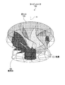
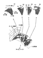
- FIG. 2 is an external perspective view of the turbine rotor according to the first embodiment.
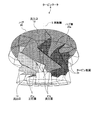
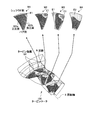
- FIG. 3 is an external perspective view of a conventional turbine rotor.
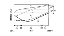
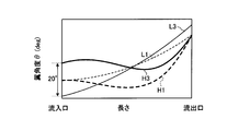
- FIG. 4 is a graph regarding the blade angle distribution of the turbine rotor blades in the shroud line and the hub line of the conventional turbine rotor and the turbine rotor of the second embodiment.
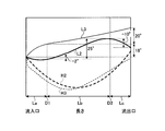
- FIG. 5 is a graph regarding the blade angle distribution of the turbine blades in the shroud line and the hub line of the turbine rotor of the first embodiment and the turbine rotor of the second embodiment.
- FIG. 6 is an external perspective view of the turbine rotor according to the second embodiment.
- FIG. 7 is a distribution diagram of turbine efficiency in the flow path of the conventional turbine rotor.
- FIG. 8 is a distribution diagram of turbine efficiency in the flow path of the turbine rotor according to the second embodiment.
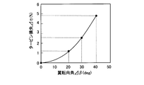
- FIG. 9 is a graph relating to a loss in turbine efficiency that varies according to the blade turning angle of the turbine rotor according to the second embodiment.
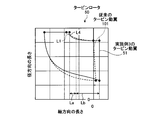
- FIG. 10 is a meridional cross-sectional view of the turbine rotor blade according to the third embodiment and the turbine rotor blade of the conventional turbine rotor.
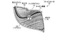
- FIG. 11 is an external perspective view illustrating a part of the turbine rotor according to the fourth embodiment.
- FIG. 12 is an external perspective view showing a part of a conventional turbine rotor.
- FIG. 13 is a graph showing the blade angle distribution in the circumferential direction ( ⁇ direction) of the turbine blade of Example 2 to which the configuration of Example 4 is applied and the conventional turbine blade.
- FIG. 14 shows the distribution of blade angles in the circumferential direction ( ⁇ direction) of the turbine rotor blade of the first embodiment to which the configuration of the fourth embodiment is applied and the turbine rotor blade of the second embodiment to which the configuration of the fourth embodiment is applied. It is the graph showing.
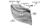
- FIG. 15 is a meridional sectional view showing streamlines of working fluid in a flow path of a conventional turbine rotor.
- FIG. 16 is a meridional sectional view showing streamlines of the working fluid in the flow path of the turbine rotor of the fourth embodiment.
- FIG. 17 is a graph showing changes in flow velocity between the pressure surface and the suction surface on the shroud side of the turbine blade according to the related art and the first embodiment.
- FIG. 18 is a graph showing pressure changes between the pressure surface and the suction surface on the shroud side of the conventional turbine blade according to the first embodiment.
- FIG. 19 is a graph showing changes in flow velocity between the pressure surface and the suction surface on the shroud side of the turbine blade according to the related art and the second embodiment.
- FIG. 20 is a graph showing changes in pressure between the pressure surface and the suction surface on the shroud side of the turbine blade according to the related art and the second embodiment.
- the turbine rotor 6 constitutes a part of the radial turbine 1, and the radial turbine 1 is a turbine casing 5 serving as an outer shell, and a turbine rotor disposed inside the turbine casing 5. 6.
- an outlet 11 is formed in the axial direction of the rotation axis S of the turbine rotor 6 disposed in the center thereof, and a spiral scroll 12 is formed in the circumferential direction outside the turbine rotor 6. . Then, the working fluid flowing in the scroll 12 flows into the turbine rotor 6 from the radial direction through the inlet 13 formed between the scroll 12 and the turbine rotor 6, passes through the turbine rotor 6, and then flows out to the outlet. 11 flows out.
- the turbine rotor 6 includes a hub 20 that rotates about a rotation axis S, and a plurality of turbine rotor blades 21 that are provided on the peripheral surface of the hub 20 and that are arranged radially from the axis. The working fluid thus received is received by a plurality of turbine rotor blades 21 and rotated.
- the turbine casing 5 has a shroud 24 facing the turbine rotor blade 21 of the turbine rotor 6, and a flow path R through which a working fluid flows is defined by the shroud 24, the hub 20, and each turbine rotor blade 21. Yes.
- Each turbine rotor blade 21 has a fixed end side (base end side) connected to the peripheral surface (hub surface 20a) of the hub 20 as a hub side, and a free end side (tip end side) close to the shroud side. ) Is on the shroud side.
- a line along the shroud side edge of the turbine blade 21 from the inlet 13 to the outlet 11 is referred to as a shroud line L ⁇ b> 2, and the turbine blade 21 from the inlet 13 to the outlet 11.
- a line along the edge on the hub side is referred to as a hub line H2.
- a gap C is formed between each turbine blade 21 and the shroud 24 so that the turbine rotor 6 can rotate.
- each turbine blade 21 receives the flowing working fluid.
- the camber surface of one turbine blade 21 constituting the flow path R is a positive pressure surface 21a
- the camber surface of the other turbine blade 21 is a negative pressure surface 21b.
- one camber surface of each turbine rotor blade 21 is a pressure surface 21a
- the other camber surface is a suction surface 21b.
- the turbine rotor blade 21 of the turbine rotor 6 of the first embodiment is shown, and the turbine rotor blade 101 of the conventional turbine rotor 100 is shown with reference to FIG. 4 and 5, the shape of the turbine rotor blade 101 of the conventional turbine rotor 100 and the shape of the turbine rotor blade 21 of the turbine rotor 6 of the first embodiment are compared with those of the turbine rotor 30 of the second embodiment described later. The comparison is made indirectly through the shape of the turbine blade 32.
- the characteristic part of the turbine rotor blade 21 of the turbine rotor 6 of the first embodiment will be described.
- FIG. 4 shows the shroud line L1 and the hub line H1 in the conventional turbine blade 101, and the shroud line L3 and the hub line H3 in the turbine blade 32 of the second embodiment.
- FIG. 5 shows the shroud line L2 and the hub line H2 in the turbine blade 21 of the first embodiment, and the shroud line L3 and the hub line H3 in the turbine blade 32 of the second embodiment.
- the change in the inclination angle (blade angle ⁇ ) of the shroud line L1 with respect to the rotation axis S gradually increases from the inlet 105 to the outlet 106.
- the change in the inclination angle (blade angle ⁇ ) of the shroud line L3 with respect to the rotation axis S from the inlet 34 to the outlet 35 is large on the inlet 34 side. It is small on the outlet 35 side.
- the change in the inclination angle (blade angle ⁇ ) of the shroud line L2 with respect to the rotation axis S from the inlet 13 to the outlet 11 is small on the inlet 13 side and large in the center. It is small on the outlet 11 side.
- the inclination angle (blade angle ⁇ ) of the hub line H1 with respect to the rotation axis S from the inlet 105 to the outlet 106 is substantially flat on the inlet 105 side. It gradually increases on the outlet 106 side.
- the inclination angle (blade angle ⁇ ) of the hub line H3 with respect to the rotation axis S decreases from the inlet 34 side to the center, and increases from the center to the outlet 35 side. ing.
- the inclination angle (blade angle ⁇ ) of the hub line H2 with respect to the rotation axis S decreases from the inlet 13 side to the center, and the turbine blade 21 flows from the center. It increases toward the outlet 11 side.
- the blade angle ⁇ in the shroud line L1 of the conventional turbine blade 101 and the blade angle ⁇ in the shroud line L2 of the turbine blade 21 of the first embodiment will be described.
- the horizontal axis is the length from the inlet 13, 105 to the outlet 11, 106 of the shroud line in the meridional section (the section including the rotation axis S).
- the axis is the blade angle ⁇ .
- the shroud lines L1 and L2 include an inlet side shroud line La (first shroud line) on the inlets 13 and 105 side, an outlet side shroud line Lc (third shroud line) on the outlets 11 and 106 side, It is comprised by the center shroud line Lb (2nd shroud line) between the entrance side shroud line La and the exit side shroud line Lc.
- the flow direction R of the working fluid from the inlets 13 and 105 to the outlets 11 and 106 is changed from the radial direction to the axial direction via the turning position D1, and the inlet side shroud line.
- La is the length between the inflow ports 13 and 105 and the turning position (turning portion) D1.
- the central shroud line Lb has a length from the turning position D1 to a predetermined position D2 that is a predetermined distance away.
- the outlet side shroud line Lc has a length from the predetermined position D2 to the outlets 11 and 106.
- the length of the inlet shroud line La is about 20% of the length of the shroud lines L1 and L2, and the length of the central shroud line Lb is about 60% of the length of the shroud lines L1 and L2.
- the length of the outlet side shroud line Lc is about 20% of the length of the shroud lines L1 and L2.
- the change in the blade angle ⁇ decreases from the inlet 105 to the outlet 106 of the shroud line L1 at a substantially constant rate. That is, the blade angle ⁇ on the shroud side of the conventional turbine rotor blade 101 is gradually inclined with respect to the rotation axis S toward the outlet 106. Specifically, the blade turning angle ⁇ per unit length of the inlet side shroud line La in the shroud line L1 and the blade turning angle ⁇ per unit length of the center / outlet side shroud line Lb are substantially the same. ing.
- the blade turning angle ⁇ is the amount of change in the blade angle ⁇ . In the conventional turbine blade 101, the blade turning angle ⁇ in the center / outlet side shroud line Lb is approximately 40 °.
- the blade angle ⁇ of the inlet shroud line La changes slightly in the decreasing direction in the shroud line L2, and the blade angle ⁇ of the central shroud line Lb.
- the blade angle ⁇ of the outlet side shroud line Lc changes in the decreasing direction. That is, the blade angle ⁇ on the shroud side of the turbine rotor blade 21 of the first embodiment is inclined from the inlet 13 to the turning position D1 while decreasing the inclination angle with respect to the rotation axis S, and from the turning position D1.
- the blade turning angle ⁇ per unit length of the central shroud line Lb is larger than the blade turning angle ⁇ per unit length of the inlet side shroud line La and the outlet side shroud line Lc.
- the blade turning angle ⁇ of the inlet shroud line La is about ⁇ 2 °
- the blade turning angle ⁇ of the central shroud line Lb is about 25 °
- the blade turning angle ⁇ of the outlet side shroud line Lc is about ⁇ 10 °.
- the change in the blade angle ⁇ of the inlet shroud line La of the turbine rotor 6 of the first embodiment is small in the inlet shroud line La, large in the central shroud line Lb, and small in the outlet shroud line Lc. can do.
- an increase in the flow velocity of the working fluid can be suppressed on the shroud side of the suction surface 21b of the turbine rotor blade 21, and a decrease in pressure on the suction surface 21b can be suppressed (details will be described later).
- the pressure difference between the pressure surface 21a and the suction surface 21b of the turbine rotor blade 21 can be suppressed, and leakage of the working fluid from the gap C between the turbine rotor blade 21 and the shroud 24 is suppressed. be able to. As described above, a decrease in turbine efficiency due to leakage of the working fluid can be suppressed.
- the turbine rotor 30 according to the second embodiment is configured in substantially the same manner as the first embodiment, and includes a hub 31 that rotates about the rotation axis S, a circumferential surface of the hub 31, and a shaft. And a plurality of turbine rotor blades 32 arranged radially from the center, and is configured to rotate by receiving the inflowing working fluid by the plurality of turbine rotor blades 32.
- the shroud line L3 of the turbine rotor blade 32 has a different shape from the shroud line L2 of the turbine rotor blade 21 of the first embodiment.
- the blade angle ⁇ in the shroud line L1 of the conventional turbine blade 101 and the blade angle ⁇ in the shroud line L3 of the turbine blade 32 of the second embodiment will be described.
- the shroud lines L1 and L3 include the inlet shroud line La on the inlets 34 and 105 side, the outlet shroud line Lc on the outlets 35 and 106 side, the inlet shroud line La, and the like. It is comprised by the center shroud line Lb between the exit side shroud lines Lc.
- the length of the inlet shroud line La is about 20% of the length of the shroud lines L1 and L3
- the length of the central shroud line Lb is about 60% of the length of the shroud lines L1 and L3.
- the length of the outlet side shroud line Lc is about 20% of the length of the shroud lines L1 and L3.
- the blade angle ⁇ of the inlet side shroud line La greatly changes in the shroud line L3 in the increasing direction, and the central shroud line Lb and the outlet are changed.
- the blade angle ⁇ of the side shroud line Lc changes small in the increasing direction. That is, the blade angle ⁇ on the shroud side of the turbine rotor blade 32 of the second embodiment is inclined from the inflow port 34 to the turning position D1, while increasing the inclination angle with respect to the rotation axis S, and the turning position D1. From the center to the outlet 11 through the predetermined position D2, the tilt angle with respect to the rotation axis S is increased while decreasing.
- the blade turning angle ⁇ per unit length of the inlet side shroud line La is larger than the blade turning angle ⁇ per unit length of the central shroud line Lb and the outlet shroud line Lc. .
- the blade turning angle ⁇ of the inlet shroud line La is about 18 °
- the blade turning angle ⁇ of the central shroud line Lb and the outlet shroud line Lc is 20 It is about °. Therefore, in the turbine rotor blade 32 of the second embodiment, the inlet shroud line La corresponds to the first shroud line
- the central shroud line Lb and the outlet shroud line Lc correspond to the second shroud line.
- FIGS. 7 and 8 the performance of the radial turbine including the conventional turbine rotor 100 configured as described above is compared with the performance of the radial turbine including the turbine rotor 30 of the second embodiment.
- a distribution diagram of the turbine efficiency when the flow path R through which the working fluid flows is cut by a cut surface orthogonal to the axial direction of the rotating shaft S is shown along the flow direction of the working fluid. 4 are shown.
- the first from the left side of the drawing is a first distribution diagram W1 of the turbine efficiency at the inlet 105
- the third from the left side of the drawing is the turbine efficiency at the outlet 106.
- a third distribution chart W3 is obtained.
- the second from the left side of the figure is the second distribution map W2 of the turbine efficiency between the inlet 105 and the outlet 106, and the fourth from the left side of the figure is the most downstream side after exiting the blade. This is the fourth distribution map W4 on the side.
- the low efficiency region E1 having a low efficiency is formed on the shroud side of the suction surface 101b, and the turbine efficiency is the shroud of the suction surface 101b in the second distribution chart W2.
- the low-efficiency region E1 is enlarged as compared with the first distribution map W1.
- the turbine efficiency is also formed in the low efficiency region E1 on the shroud side of the pressure surface 101a.
- the turbine efficiency is determined between the pressure surface 101a and the suction surface 101b.
- a medium efficiency region E2 having higher efficiency than the low efficiency region E1 is formed.
- FIG. 8 in the turbine rotor 30 of the second embodiment, a distribution diagram of the turbine efficiency when the flow path R through which the working fluid flows is cut by a cut surface orthogonal to the axial direction of the rotating shaft S is illustrated. Four are shown along the flow direction.
- the first distribution graph W1 of the turbine efficiency at the inlet 13 is the first from the left side in the figure, and the third from the left side is the turbine efficiency at the outlet 11 in the figure.
- a third distribution chart W3 is obtained.
- the second from the left side of the figure is a second distribution chart W2 of the turbine efficiency between the inlet 34 and the outlet 35, and the fourth on the left side of the figure is the most downstream side after exiting the blade. This is the fourth distribution map W4 on the side.
- the turbine efficiency is slightly lower than the conventional turbine rotor 100 shown in FIG. 7, although the low efficiency region E1 is slightly formed on the shroud side of the suction surface 32b.
- the turbine efficiency is such that a medium efficiency region E2 is formed on the shroud side of the suction surface 32b.
- the turbine efficiency is formed in the middle efficiency region E2 on the shroud side of the pressure surface 32a.
- the turbine efficiency is substantially equal to the low efficiency region E1 and The middle efficiency region E2 is not formed, and the high efficiency region E3 is more efficient than the middle efficiency region E2.
- the turbine efficiency that changes according to the blade turning angle ⁇ of the turbine rotor blade 32 of the turbine rotor 30 of the second embodiment will be described.
- the vertical axis represents the turbine efficiency loss rate ⁇
- the horizontal axis represents the blade turning angle ⁇ in the center / exit side shroud lines Lb and Lc.
- the loss of turbine efficiency increases as the blade turning angle ⁇ in the center / outlet side shroud lines Lb, Lc increases. For this reason, if the blade turning angle ⁇ is reduced, the loss of turbine efficiency can be suppressed.
- the conventional turbine rotor 100 has a blade turning angle ⁇ of 40 °
- the turbine rotor 6 of Example 2 has a blade turning angle ⁇ of 20 °.
- the turbine efficiency loss can be halved compared to the conventional turbine efficiency loss. For this reason, if the blade turning angle ⁇ is 30 ° or less, the efficiency loss of the radial turbine 1 can be sufficiently suppressed.
- the blade turning angle ⁇ per unit length in the center / outlet side shroud lines Lb and Lc of the turbine rotor 30 of the second embodiment can be reduced as compared with the conventional configuration.
- the turbine rotor blade 32 in the center / outlet side shroud lines Lb and Lc can be made substantially straight.
- an increase in the flow velocity of the working fluid can be suppressed on the shroud side of the suction surface 32b of the turbine rotor blade 32, and a decrease in pressure on the suction surface 32b can be suppressed (details will be described later).
- the pressure difference between the positive pressure surface 32 a and the negative pressure surface 32 b of the turbine rotor blade 32 can be suppressed, and leakage of the working fluid from the gap C between the turbine rotor blade 32 and the shroud 24 is suppressed. be able to. As described above, a decrease in turbine efficiency due to leakage of the working fluid can be suppressed.
- the center / exit side shroud lines Lb and Lc of the turbine rotor blade 32 can be made closer to a straight line.
- Example 2 20% of the length of the shroud line L3 is the inlet side shroud line La and 80% is the center / outlet side shroud lines Lb and Lc, but 10% of the length of the shroud line L3 is
- the inlet side shroud line La may be used, and 90% of the center and outlet side shroud lines Lb and Lc may be used.
- the loss of turbine efficiency can be reduced to half or less as compared with the prior art.
- FIG. 10 is a meridional sectional view of the turbine rotor blades 51 and 101 of the turbine rotor 50 according to the third embodiment and the conventional turbine rotor 100.
- the inlet side shroud line La of the turbine rotor blade 51 is formed in an R shape
- the center / outlet side shroud line Lb is formed in a substantially linear shape.
- the vertical axis represents the length in the radial direction
- the horizontal axis represents the length in the axial direction.
- the shroud line L1 is formed on a downward slope, but in the turbine rotor blade 51 of the third embodiment, the inlet shroud line La has a small curvature in the shroud line L4.
- the center and outlet side shroud lines Lb and Lc are formed with a larger curvature than the inlet side shroud line La.
- the inlet side shroud line La in the meridional section is 20% of the length of the shroud line L4, and the center / outlet side shroud lines Lb and Lc are 80% of the length of the shroud line L4.
- the inlet side shroud line La is formed in an R shape, and the center / outlet side shroud lines Lb and Lc are formed in a substantially linear shape.
- the curvature of the inlet side shroud line La can be made smaller than the curvature of the center / outlet side shroud lines Lb and Lc. For this reason, the curvature of the center / exit side shroud lines Lb, Lc can be increased, and the center / exit side shroud lines Lb, Lc can be formed substantially linearly. Thereby, an increase in the flow velocity of the working fluid can be suppressed on the suction surface on the shroud side of the turbine rotor blade 51.
- the configuration of the third embodiment may be combined with the configuration of the first or second embodiment, and thereby, a decrease in turbine efficiency can be suitably suppressed.
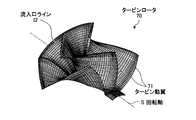
- FIG. 11 is an external perspective view showing a part of the turbine rotor 70 according to the fourth embodiment
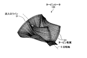
- FIG. 12 is an external perspective view showing a part of the conventional turbine rotor 100
- FIG. 13 is a graph regarding the distribution of the blade angle ⁇ of the turbine rotor blade in the circumferential direction ( ⁇ direction) when the configuration of the turbine rotor blade 71 of the fourth embodiment is applied to the turbine rotor blade 32 of the second embodiment. .
- FIG. 13 is a graph regarding the distribution of the blade angle ⁇ of the turbine rotor blade in the circumferential direction ( ⁇ direction) when the configuration of the turbine rotor blade 71 of the fourth embodiment is applied to the turbine rotor blade 32 of the second embodiment. .
- FIG. 11 is an external perspective view showing a part of the turbine rotor 70 according to the fourth embodiment
- FIG. 12 is an external perspective view showing a part of the conventional turbine rotor 100.
- FIG. 13 is a graph regarding the distribution of the blade angle ⁇ of the turbine rot
- FIG. 14 is a graph relating to the distribution of the blade angle ⁇ of the turbine rotor blade in the circumferential direction ( ⁇ direction) when the configuration of the turbine rotor blade 71 of the fourth embodiment is applied to the turbine rotor blade 21 of the first embodiment. is there.
- FIG. 15 is a meridional sectional view showing a streamline of the working fluid in the flow path of the conventional turbine rotor
- FIG. 16 is a streamline of the working fluid in the flow path of the turbine rotor 70 of the fourth embodiment.
- an inlet line I2 that is a line along the inlet side edge of the turbine rotor blade 71 is inclined with respect to the rotation axis S in the rotation direction.
- the conventional inlet line I1 is formed so as to be substantially in the same direction as the rotation axis S. That is, as shown in FIG. 13, the angle (blade angle ⁇ ) in the circumferential direction on the inlet 105 side of the shroud line L1 is the same as the angle (blade angle ⁇ ) in the circumferential direction on the inlet 105 side of the hub line H1. It is an angle and has the same phase in the circumferential direction.
- the conventional inlet line I1 from the inlet 105 of the hub line H1 to the inlet 105 of the shroud line L1 is not displaced in the circumferential direction, and is therefore substantially in the same direction as the rotation axis S.
- the inlet line I2 of the turbine rotor blade 32 of the second embodiment to which the configuration of the turbine rotor blade 71 of the fourth embodiment is applied as shown in FIGS. 13 and 14, the inlet of the shroud line L3 of the second embodiment.
- the angle difference between the blade angle ⁇ in the circumferential direction on the side and the blade angle ⁇ in the circumferential direction on the inlet side of the hub line H3 is about 20 ° to 22 °, and the phases are different in the circumferential direction.
- the inlet line I2 of the third embodiment from the inlet 34 of the hub line H3 to the inlet 34 of the shroud line L3 is displaced in the circumferential direction (rotation direction), whereby the inlet line I2 is rotated on the rotation axis. It is inclined in the rotational direction with respect to S.
- the inlet line I2 of the turbine rotor blade 21 of the first embodiment to which the configuration of the turbine rotor blade 71 of the fourth embodiment is applied as shown in FIG. 14, the peripheral side of the inlet side of the shroud line L2 of the first embodiment.
- the angle difference between the blade angle ⁇ in the direction and the blade angle ⁇ in the circumferential direction on the inlet side of the hub line H2 is about 12 °, and the phases are different in the circumferential direction.
- the inlet line I2 of Example 1 from the inlet 13 of the hub line H2 to the inlet 11 of the shroud line L2 is displaced in the circumferential direction (rotation direction). It is inclined in the rotational direction with respect to S.
- the working fluid flowing from the inlet 34 can be directed to the hub side. For this reason, it can suppress that a working fluid flows into the clearance gap C between the turbine rotor blade 32 and the shroud 24 toward a shroud side, and, thereby, suppresses that a working fluid leaks from the clearance gap C. can do.
- Example 4 the angular difference between the blade angle ⁇ in the circumferential direction on the inlets 13 and 34 side of the shroud lines L2 and L3 and the blade angle ⁇ in the circumferential direction on the inlets 13 and 34 side of the hub lines H2 and H3.
- the angle is between 10 ° and 25 °, the leakage of the working fluid can be suitably suppressed.
- the change in the blade angle ⁇ of the central shroud line Lb is larger than the change in the blade angle ⁇ of the inlet side shroud line La and the outlet side shroud line Lc. Further, the angle difference between the blade angle ⁇ on the inlet side of the shroud line L2 and the blade angle ⁇ on the inlet side of the hub line H2 is about 12 °.
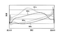
- FIG. 17 is a graph showing changes in flow velocity between the pressure surface and the suction surface on the shroud side of the conventional turbine blade according to the first embodiment
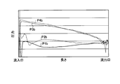
- FIG. 18 is a graph illustrating the turbine blade according to the conventional and the first embodiment. It is a graph which shows the pressure change of the positive pressure surface and negative pressure surface in the shroud side.
- M1a is a graph of the flow velocity change of the suction surface 101b on the shroud side of the turbine rotor blade 101 of the conventional turbine rotor 100
- M2a is the turbine rotor 6 in which the first embodiment is combined with the fourth embodiment. It is a graph of the flow velocity change of the negative pressure surface 21b in the shroud side of the turbine rotor blade 21.
- M3a is a graph of the flow velocity change of the pressure surface 101a on the shroud side of the turbine rotor blade 101 of the conventional turbine rotor 100
- M4a is the turbine rotor blade of the turbine rotor 6 in which the first embodiment is combined with the fourth embodiment.
- 21 is a graph of changes in the flow velocity of the pressure surface 21a on the shroud side of 21.
- M3a and M4a have almost the same change in flow velocity, whereas M1a and M2a have different changes in flow velocity. Specifically, it can be seen that M1a has a large change in flow rate in the middle, while M2a has a small change in flow rate compared to M1a.
- the vertical axis represents the pressure of the working fluid
- the horizontal axis represents the distance from the inlet to the outlet of the working fluid flow path R in the meridional section.
- P1a is a graph of the pressure change of the suction surface 101b on the shroud side of the turbine rotor blade 101 of the conventional turbine rotor 100
- P2a is the turbine rotor 6 in which the first embodiment is combined with the fourth embodiment. It is a graph of the pressure change of the suction surface 21b in the shroud side of the turbine rotor blade 21 of this.
- P3a is a graph of the pressure change of the pressure surface 101a on the shroud side of the turbine rotor blade 101 of the conventional turbine rotor 100
- P4a is the turbine rotor blade of the turbine rotor 6 in which the first embodiment is combined with the fourth embodiment.
- 21 is a graph of the pressure change of the pressure surface 21a on the shroud side of FIG.
- P3a and P4a have almost the same change in pressure, whereas P1a and P2a have different pressure changes. Specifically, P1a has a lower pressure in the middle, while P2a has a higher pressure in the middle than P1a. Thereby, it turns out that the pressure difference of P4a and P2a becomes small compared with the pressure difference of P3a and P1a.
- the change in the blade angle ⁇ of the inlet shroud line La changes with the change in the blade angle ⁇ of the central and outlet shroud lines Lb and Lc.
- the inlet side shroud line La of the turbine blade is formed in an R shape, and the central and outlet side shroud lines Lb and Lc of the turbine blade are formed in a substantially linear shape.
- the angle difference between the blade angle ⁇ on the inlet side of the shroud line L3 and the blade angle ⁇ on the inlet side of the hub line H3 is about 20 °.
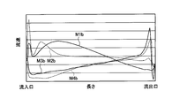
- FIG. 19 is a graph showing changes in flow velocity between the pressure surface and the suction surface on the shroud side of the conventional turbine blade according to the second embodiment
- FIG. 20 is a graph illustrating the turbine blade according to the conventional and second embodiment. It is a graph which shows the pressure change of the positive pressure surface and negative pressure surface in the shroud side.
- M1b is a graph of the flow velocity change of the suction surface 101b on the shroud side of the turbine rotor blade 101 of the conventional turbine rotor 100
- M2b is a turbine in which the second embodiment is combined with the third and fourth embodiments.
- 4 is a graph of a change in flow velocity of a suction surface 32b on a shroud side of a turbine rotor blade 32 of a rotor 30.
- M3b is a graph of the flow velocity change of the pressure surface 101a on the shroud side of the turbine rotor blade 101 of the conventional turbine rotor 100
- M4b is a turbine of the turbine rotor 30 in which the third and fourth embodiments are combined with the second embodiment.
- 4 is a graph of a change in flow velocity of a pressure surface 32a on the shroud side of a moving blade 32.
- M3b and M4b have almost the same change in flow velocity, whereas M1b and M2b have different flow velocity changes. Specifically, it can be seen that the change in the flow velocity becomes larger in the middle of M1b, while the change in the flow velocity becomes smaller in M2b compared to M1b.
- the vertical axis represents the pressure of the working fluid
- the horizontal axis represents the distance from the inlet to the outlet of the working fluid flow path R in the meridional section.
- P1b is a graph of the pressure change of the suction surface 101b on the shroud side of the turbine rotor blade 101 of the conventional turbine rotor 100
- P2b is a turbine in which the second embodiment is combined with the third and fourth embodiments.
- 4 is a graph of a pressure change of a suction surface 32b on a shroud side of a turbine rotor blade 32 of a rotor 30.
- P3b is a graph of the pressure change of the pressure surface 101a on the shroud side of the turbine rotor blade 101 of the conventional turbine rotor 100
- P4b is a turbine of the turbine rotor 30 in which the third and fourth embodiments are combined with the second embodiment.
- 4 is a graph of pressure change of the pressure surface 32a on the shroud side of the moving blade 32.
- P3b and P4b have almost the same change in pressure, whereas P1b and P2b have different pressure changes. Specifically, P1b has a lower pressure in the middle, while P2b has a higher pressure in the middle than P1b. Thereby, it turns out that the pressure difference of P4b and P2b becomes small compared with the pressure difference of P3b and P1b.
- the change in the flow velocity of the working fluid flowing on the suction surface 21b on the shroud side of the turbine rotor blade 21 is smaller than that in the related art.
- the pressure difference between P4a and P2a can be made smaller than the pressure difference between P3a and P1a.
- the change in the flow velocity of the working fluid flowing on the suction surface 32b on the shroud side of the turbine rotor blade 32 is smaller than that in the related art. Therefore, the pressure difference between P4b and P2b can be made smaller than the pressure difference between P3b and P1b.
- the present invention is applied to a radial turbine.
- the present invention may be applied to a mixed flow turbine or an axial flow turbine.
- the turbine rotor according to the present invention is useful for a turbine rotor in which a gap is formed between a turbine rotor blade and a shroud, and in particular, leakage of working fluid from the gap is suppressed to improve turbine efficiency. Suitable for improvement.
Landscapes
- Engineering & Computer Science (AREA)
- Mechanical Engineering (AREA)
- General Engineering & Computer Science (AREA)
- Physics & Mathematics (AREA)
- Fluid Mechanics (AREA)
- Turbine Rotor Nozzle Sealing (AREA)
Abstract
Description
5 タービンケーシング
6 タービンロータ
11 流出口
13 流入口
20 ハブ
21 タービン動翼
24 シュラウド
30 タービンロータ(実施例2)
32 タービン動翼(実施例2)
34 流入口
35 流出口
50 タービンロータ(実施例2)
51 タービン動翼(実施例2)
70 タービンロータ(実施例3)
71 タービン動翼(実施例3)
75 流入口(実施例3)
76 流出口(実施例3)
100 タービンロータ(従来)
101 タービン動翼(従来)
105 流入口(従来)
106 流出口(従来)
C 隙間
L1 シュラウドライン(従来)
L2 シュラウドライン(実施例1)
L3 シュラウドライン(実施例2)
H1 ハブライン(従来)
H2 ハブライン(実施例1)
H3 ハブライン(実施例2)
La 入口側シュラウドライン
Lb 中央シュラウドライン
Lc 出口側シュラウドライン
D1 転向位置
D2 所定位置
β 翼角度
Δβ 翼転向角
θ 翼角度
I1 流入口ライン(従来)
I2 流入口ライン(本発明)
Claims (11)
- 流入口を介して径方向から流入した作動流体を、流出口を介して軸方向に流出させるタービンのタービンロータにおいて、
回転軸を中心に回転可能なハブと、
前記ハブの周面に設けられ、前記流入口から流入する前記作動流体を前記流出口へ向けて受け流す複数のタービン動翼と、を備え、
前記各タービン動翼は、前記ハブに接続された基端側がハブ側となっており、自由端となる先端側がシュラウド側となっており、
前記タービン動翼のシュラウド側縁部に沿った前記流入口から前記流出口へ至るラインをシュラウドラインとし、
前記シュラウドラインは、前記回転軸に対する翼角度が、前記流入口から前記流出口へ向けて小さな変化となる第1シュラウドラインと、前記第1シュラウドラインの前記流出口側に連なり、前記第1シュラウドラインよりも大きな変化となる第2シュラウドラインと、前記第2シュラウドラインの前記流出口側から前記流出口まで連なり、前記第2シュラウドラインよりも小さな変化となる第3シュラウドラインと、で構成されていることを特徴とするタービンロータ。 - 前記第3シュラウドラインの翼角度の変化は、減少方向への変化となっていることを特徴とする請求項1に記載のタービンロータ。
- 流入口を介して径方向から流入した作動流体を、流出口を介して軸方向に流出させるタービンのタービンロータにおいて、
回転軸を中心に回転可能なハブと、
前記ハブの周面に設けられ、前記流入口から流入する前記作動流体を前記流出口へ向けて受け流す複数のタービン動翼と、を備え、
前記各タービン動翼は、
前記ハブに接続された基端側がハブ側となっており、自由端となる先端側がシュラウド側となっており、
前記タービン動翼のシュラウド側縁部に沿った前記流入口から前記流出口へ至るラインをシュラウドラインとし、
前記シュラウドラインは、前記回転軸に対する翼角度が、前記流入口から前記流出口へ向けて大きな変化となる第1シュラウドラインと、前記第1シュラウドラインの前記流出口側から前記流出口まで連なり、前記第1シュラウドラインよりも小さな変化となる第2シュラウドラインと、で構成されていることを特徴とするタービンロータ。 - 前記第1シュラウドラインの長さは、前記シュラウドラインの長さの1~2割の長さとなっており、前記第2シュラウドラインの長さは、前記シュラウドラインの長さから前記第1シュラウドラインの長さを引いた、前記シュラウドラインの長さの8~9割の長さとなっていることを特徴とする請求項3に記載のタービンロータ。
- 前記第2シュラウドラインにおける前記翼角度の変化量となる翼転向角は、30°以下であることを特徴とする請求項3または4に記載のタービンロータ。
- 前記シュラウドラインは、前記第1シュラウドラインが、前記流入口側のシュラウドラインとなる入口側シュラウドラインであり、前記第2シュラウドラインが、前記入口側シュラウドラインの前記流出口側から前記流出口まで連なる中央・出口側シュラウドラインであり、
前記ハブの回転軸を含む断面となる子午断面において、前記入口側シュラウドラインの曲率は、前記中央・出口側シュラウドラインの曲率に比して、小さくなっていることを特徴とする請求項3ないし5のいずれか1項に記載のタービンロータ。 - 前記入口側シュラウドラインは、R状に形成される一方、前記中央・出口側シュラウドラインは、直線状に形成されていることを特徴とする請求項6に記載のタービンロータ。
- 前記各タービン動翼の前記流入口側縁部に沿ったラインである流入口ラインは、前記回転軸に対し、回転方向へ傾いていることを特徴とする請求項1ないし7のいずれか1項に記載のタービンロータ。
- 前記回転軸に対する前記流入口ラインの傾斜角度は、10°~25°であることを特徴とする請求項8に記載のタービンロータ。
- 流入口を介して径方向から流入した作動流体を、流出口を介して軸方向に流出させるタービンのタービンロータにおいて、
回転軸を中心に回転可能なハブと、
前記ハブの周面に設けられ、前記流入口から流入する前記作動流体を前記流出口へ向けて受け流す複数のタービン動翼と、を備え、
前記各タービン動翼は、
前記ハブに接続された基端側がハブ側となっており、自由端となる先端側がシュラウド側となっており、
前記タービン動翼のシュラウド側縁部に沿ったラインをシュラウドラインとし、
前記シュラウドラインは、前記流入口側のシュラウドラインとなる入口側シュラウドラインと、前記入口側シュラウドラインの前記流出口側から前記流出口まで連なる中央・出口側シュラウドラインと、で構成され、
前記ハブの回転軸を含む断面となる子午断面において、前記入口側シュラウドラインの曲率は、前記中央・出口側シュラウドラインの曲率に比して、小さくなっていることを特徴とするタービンロータ。 - 流入口を介して径方向から流入した作動流体を、流出口を介して軸方向に流出させるタービンのタービンロータにおいて、
回転軸を中心に回転可能なハブと、
前記ハブの周面に設けられ、前記流入口から流入する前記作動流体を前記流出口へ向けて受け流す複数のタービン動翼と、を備え、
前記各タービン動翼の前記流入口側縁部に沿ったラインである流入口ラインは、前記回転軸に対し、回転方向へ傾いていることを特徴とするタービンロータ。
Priority Applications (5)
| Application Number | Priority Date | Filing Date | Title |
|---|---|---|---|
| CN201080026091.6A CN102459818B (zh) | 2009-06-26 | 2010-02-16 | 涡轮转子 |
| KR1020117030839A KR101326470B1 (ko) | 2009-06-26 | 2010-02-16 | 터빈 로터 |
| US13/376,554 US9039374B2 (en) | 2009-06-26 | 2010-02-16 | Turbine rotor |
| EP10791888.0A EP2447473B1 (en) | 2009-06-26 | 2010-02-16 | Turbine rotor |
| US14/692,451 US9353630B2 (en) | 2009-06-26 | 2015-04-21 | Turbine rotor |
Applications Claiming Priority (2)
| Application Number | Priority Date | Filing Date | Title |
|---|---|---|---|
| JP2009152829A JP5371578B2 (ja) | 2009-06-26 | 2009-06-26 | タービンロータ |
| JP2009-152829 | 2009-06-26 |
Related Child Applications (2)
| Application Number | Title | Priority Date | Filing Date |
|---|---|---|---|
| US13/376,554 A-371-Of-International US9039374B2 (en) | 2009-06-26 | 2010-02-16 | Turbine rotor |
| US14/692,451 Division US9353630B2 (en) | 2009-06-26 | 2015-04-21 | Turbine rotor |
Publications (1)
| Publication Number | Publication Date |
|---|---|
| WO2010150567A1 true WO2010150567A1 (ja) | 2010-12-29 |
Family
ID=43386350
Family Applications (1)
| Application Number | Title | Priority Date | Filing Date |
|---|---|---|---|
| PCT/JP2010/052266 Ceased WO2010150567A1 (ja) | 2009-06-26 | 2010-02-16 | タービンロータ |
Country Status (6)
| Country | Link |
|---|---|
| US (2) | US9039374B2 (ja) |
| EP (1) | EP2447473B1 (ja) |
| JP (1) | JP5371578B2 (ja) |
| KR (1) | KR101326470B1 (ja) |
| CN (1) | CN102459818B (ja) |
| WO (1) | WO2010150567A1 (ja) |
Cited By (1)
| Publication number | Priority date | Publication date | Assignee | Title |
|---|---|---|---|---|
| CN103003527A (zh) * | 2011-01-27 | 2013-03-27 | 三菱重工业株式会社 | 径流式涡轮 |
Families Citing this family (12)
| Publication number | Priority date | Publication date | Assignee | Title |
|---|---|---|---|---|
| JP5371578B2 (ja) * | 2009-06-26 | 2013-12-18 | 三菱重工業株式会社 | タービンロータ |
| GB201103222D0 (en) * | 2011-02-24 | 2011-04-13 | Imp Innovations Ltd | A turbine wheel,a turbine and a use thereof |
| JP5811548B2 (ja) * | 2011-02-28 | 2015-11-11 | 株式会社Ihi | ツインスクロール型の斜流タービン及び過給機 |
| US9777578B2 (en) | 2012-12-27 | 2017-10-03 | Mitsubishi Heavy Industries, Ltd. | Radial turbine blade |
| JP2015086710A (ja) * | 2013-10-28 | 2015-05-07 | 株式会社日立製作所 | ガスパイプライン用遠心圧縮機及びガスパイプライン |
| EP3205885A1 (de) * | 2016-02-10 | 2017-08-16 | Siemens Aktiengesellschaft | Verdichterlaufschaufel und verfahren zum profilieren der verdichterlaufschaufel |
| DE102016102732A1 (de) * | 2016-02-17 | 2017-08-17 | Volkswagen Aktiengesellschaft | Mixed-Flow-Turbinenrad eines Abgasturboladers sowie Abgasturbine mit einem solchen Turbinenrad |
| JP6583946B2 (ja) | 2016-03-02 | 2019-10-02 | 三菱重工エンジン&ターボチャージャ株式会社 | タービンホイール、ラジアルタービン、及び過給機 |
| EP3636880B1 (de) * | 2018-10-11 | 2023-06-07 | BorgWarner, Inc. | Turbinenrad |
| CN109184804B (zh) * | 2018-11-02 | 2021-04-13 | 北京控制工程研究所 | 一种空间布雷顿循环系统用的透平叶轮 |
| JP7140030B2 (ja) * | 2019-03-28 | 2022-09-21 | 株式会社豊田自動織機 | 燃料電池用遠心圧縮機 |
| WO2022196234A1 (ja) | 2021-03-17 | 2022-09-22 | 株式会社Ihi | タービンおよび過給機 |
Citations (4)
| Publication number | Priority date | Publication date | Assignee | Title |
|---|---|---|---|---|
| JPH10504621A (ja) * | 1994-06-10 | 1998-05-06 | 株式会社 荏原製作所 | 遠心または斜流ターボ機械 |
| JP2008503677A (ja) * | 2004-06-19 | 2008-02-07 | ダイムラー・アクチェンゲゼルシャフト | 排気ガスターボチャージャのタービンホイール |
| JP2008133766A (ja) * | 2006-11-28 | 2008-06-12 | Ihi Corp | タービンインペラ |
| JP2008133765A (ja) | 2006-11-28 | 2008-06-12 | Ihi Corp | タービンインペラ |
Family Cites Families (5)
| Publication number | Priority date | Publication date | Assignee | Title |
|---|---|---|---|---|
| JP3377629B2 (ja) | 1994-11-21 | 2003-02-17 | 三菱重工業株式会社 | ラジアルタービン |
| JP4288051B2 (ja) * | 2002-08-30 | 2009-07-01 | 三菱重工業株式会社 | 斜流タービン、及び、斜流タービン動翼 |
| JP4691002B2 (ja) * | 2006-11-20 | 2011-06-01 | 三菱重工業株式会社 | 斜流タービンまたはラジアルタービン |
| US8308420B2 (en) * | 2007-08-03 | 2012-11-13 | Hitachi Plant Technologies, Ltd. | Centrifugal compressor, impeller and operating method of the same |
| JP5371578B2 (ja) * | 2009-06-26 | 2013-12-18 | 三菱重工業株式会社 | タービンロータ |
-
2009
- 2009-06-26 JP JP2009152829A patent/JP5371578B2/ja not_active Expired - Fee Related
-
2010
- 2010-02-16 CN CN201080026091.6A patent/CN102459818B/zh active Active
- 2010-02-16 EP EP10791888.0A patent/EP2447473B1/en active Active
- 2010-02-16 WO PCT/JP2010/052266 patent/WO2010150567A1/ja not_active Ceased
- 2010-02-16 KR KR1020117030839A patent/KR101326470B1/ko not_active Expired - Fee Related
- 2010-02-16 US US13/376,554 patent/US9039374B2/en active Active
-
2015
- 2015-04-21 US US14/692,451 patent/US9353630B2/en active Active
Patent Citations (4)
| Publication number | Priority date | Publication date | Assignee | Title |
|---|---|---|---|---|
| JPH10504621A (ja) * | 1994-06-10 | 1998-05-06 | 株式会社 荏原製作所 | 遠心または斜流ターボ機械 |
| JP2008503677A (ja) * | 2004-06-19 | 2008-02-07 | ダイムラー・アクチェンゲゼルシャフト | 排気ガスターボチャージャのタービンホイール |
| JP2008133766A (ja) * | 2006-11-28 | 2008-06-12 | Ihi Corp | タービンインペラ |
| JP2008133765A (ja) | 2006-11-28 | 2008-06-12 | Ihi Corp | タービンインペラ |
Cited By (3)
| Publication number | Priority date | Publication date | Assignee | Title |
|---|---|---|---|---|
| CN103003527A (zh) * | 2011-01-27 | 2013-03-27 | 三菱重工业株式会社 | 径流式涡轮 |
| US8845278B2 (en) | 2011-01-27 | 2014-09-30 | Mitsubishi Heavy Industries, Ltd. | Radial turbine |
| CN103003527B (zh) * | 2011-01-27 | 2015-08-26 | 三菱重工业株式会社 | 径流式涡轮 |
Also Published As
| Publication number | Publication date |
|---|---|
| US9353630B2 (en) | 2016-05-31 |
| JP5371578B2 (ja) | 2013-12-18 |
| CN102459818B (zh) | 2014-11-19 |
| KR101326470B1 (ko) | 2013-11-07 |
| US9039374B2 (en) | 2015-05-26 |
| EP2447473B1 (en) | 2019-12-18 |
| KR20120014217A (ko) | 2012-02-16 |
| US20120082552A1 (en) | 2012-04-05 |
| CN102459818A (zh) | 2012-05-16 |
| US20150300178A1 (en) | 2015-10-22 |
| EP2447473A4 (en) | 2018-03-14 |
| JP2011007141A (ja) | 2011-01-13 |
| EP2447473A1 (en) | 2012-05-02 |
Similar Documents
| Publication | Publication Date | Title |
|---|---|---|
| JP5371578B2 (ja) | タービンロータ | |
| US9797254B2 (en) | Group of blade rows | |
| US20080131268A1 (en) | Turbomachine with variable guide/stator blades | |
| US9822645B2 (en) | Group of blade rows | |
| CN101713364B (zh) | 水力机械 | |
| JP6470578B2 (ja) | 遠心圧縮機 | |
| WO2011007466A1 (ja) | インペラおよび回転機械 | |
| JP4882939B2 (ja) | 可動翼軸流ポンプ | |
| JP5314441B2 (ja) | 遠心型水力機械 | |
| WO2017072843A1 (ja) | 回転機械 | |
| JP6239258B2 (ja) | 軸流水車 | |
| JP6234343B2 (ja) | 回転機械 | |
| JP5248422B2 (ja) | ターボ機械及び水車ランナ | |
| JP5287329B2 (ja) | ポンプインペラ | |
| JP6605147B2 (ja) | ターボチャージャ及びターボチャージャのノズルベーン並びにタービン | |
| JP4893125B2 (ja) | 両吸込渦巻ポンプ | |
| JP4084112B2 (ja) | フランシス水車ランナ、およびフランシス水車 | |
| JP6710597B2 (ja) | ポンプ | |
| JP5125868B2 (ja) | ポンプインペラとインペラ翼 | |
| JP2011252431A (ja) | タービンインペラ | |
| JPH05248385A (ja) | 渦流型羽根車 |
Legal Events
| Date | Code | Title | Description |
|---|---|---|---|
| WWE | Wipo information: entry into national phase |
Ref document number: 201080026091.6 Country of ref document: CN |
|
| 121 | Ep: the epo has been informed by wipo that ep was designated in this application |
Ref document number: 10791888 Country of ref document: EP Kind code of ref document: A1 |
|
| WWE | Wipo information: entry into national phase |
Ref document number: 13376554 Country of ref document: US Ref document number: 2010791888 Country of ref document: EP |
|
| ENP | Entry into the national phase |
Ref document number: 20117030839 Country of ref document: KR Kind code of ref document: A |
|
| NENP | Non-entry into the national phase |
Ref country code: DE |