WO2010150763A1 - 廃棄物収容装置用パッケージ装置及び廃棄物収容装置 - Google Patents
廃棄物収容装置用パッケージ装置及び廃棄物収容装置 Download PDFInfo
- Publication number
- WO2010150763A1 WO2010150763A1 PCT/JP2010/060506 JP2010060506W WO2010150763A1 WO 2010150763 A1 WO2010150763 A1 WO 2010150763A1 JP 2010060506 W JP2010060506 W JP 2010060506W WO 2010150763 A1 WO2010150763 A1 WO 2010150763A1
- Authority
- WO
- WIPO (PCT)
- Prior art keywords
- waste
- rollers
- friction
- waste container
- roller
- Prior art date
- Legal status (The legal status is an assumption and is not a legal conclusion. Google has not performed a legal analysis and makes no representation as to the accuracy of the status listed.)
- Ceased
Links
Images


Classifications
-
- B—PERFORMING OPERATIONS; TRANSPORTING
- B65—CONVEYING; PACKING; STORING; HANDLING THIN OR FILAMENTARY MATERIAL
- B65F—GATHERING OR REMOVAL OF DOMESTIC OR LIKE REFUSE
- B65F1/00—Refuse receptacles; Accessories therefor
- B65F1/04—Refuse receptacles; Accessories therefor with removable inserts
- B65F1/06—Refuse receptacles; Accessories therefor with removable inserts with flexible inserts, e.g. bags or sacks
- B65F1/062—Refuse receptacles; Accessories therefor with removable inserts with flexible inserts, e.g. bags or sacks having means for storing or dispensing spare bags
-
- B—PERFORMING OPERATIONS; TRANSPORTING
- B65—CONVEYING; PACKING; STORING; HANDLING THIN OR FILAMENTARY MATERIAL
- B65F—GATHERING OR REMOVAL OF DOMESTIC OR LIKE REFUSE
- B65F1/00—Refuse receptacles; Accessories therefor
- B65F1/04—Refuse receptacles; Accessories therefor with removable inserts
- B65F1/06—Refuse receptacles; Accessories therefor with removable inserts with flexible inserts, e.g. bags or sacks
-
- B—PERFORMING OPERATIONS; TRANSPORTING
- B65—CONVEYING; PACKING; STORING; HANDLING THIN OR FILAMENTARY MATERIAL
- B65B—MACHINES, APPARATUS OR DEVICES FOR, OR METHODS OF, PACKAGING ARTICLES OR MATERIALS; UNPACKING
- B65B9/00—Enclosing successive articles, or quantities of material, e.g. liquids or semiliquids, in flat, folded, or tubular webs of flexible sheet material; Subdividing filled flexible tubes to form packages
- B65B9/02—Enclosing successive articles, or quantities of material between opposed webs
-
- B—PERFORMING OPERATIONS; TRANSPORTING
- B65—CONVEYING; PACKING; STORING; HANDLING THIN OR FILAMENTARY MATERIAL
- B65F—GATHERING OR REMOVAL OF DOMESTIC OR LIKE REFUSE
- B65F1/00—Refuse receptacles; Accessories therefor
- B65F1/14—Other constructional features; Accessories
- B65F1/16—Lids or covers
- B65F1/1607—Lids or covers with filling openings
-
- B—PERFORMING OPERATIONS; TRANSPORTING
- B29—WORKING OF PLASTICS; WORKING OF SUBSTANCES IN A PLASTIC STATE IN GENERAL
- B29C—SHAPING OR JOINING OF PLASTICS; SHAPING OF MATERIAL IN A PLASTIC STATE, NOT OTHERWISE PROVIDED FOR; AFTER-TREATMENT OF THE SHAPED PRODUCTS, e.g. REPAIRING
- B29C65/00—Joining or sealing of preformed parts, e.g. welding of plastics materials; Apparatus therefor
- B29C65/002—Joining methods not otherwise provided for
- B29C65/008—Joining methods not otherwise provided for making use of electrostatic charges
-
- B—PERFORMING OPERATIONS; TRANSPORTING
- B29—WORKING OF PLASTICS; WORKING OF SUBSTANCES IN A PLASTIC STATE IN GENERAL
- B29C—SHAPING OR JOINING OF PLASTICS; SHAPING OF MATERIAL IN A PLASTIC STATE, NOT OTHERWISE PROVIDED FOR; AFTER-TREATMENT OF THE SHAPED PRODUCTS, e.g. REPAIRING
- B29C66/00—General aspects of processes or apparatus for joining preformed parts
- B29C66/01—General aspects dealing with the joint area or with the area to be joined
- B29C66/05—Particular design of joint configurations
- B29C66/10—Particular design of joint configurations particular design of the joint cross-sections
- B29C66/11—Joint cross-sections comprising a single joint-segment, i.e. one of the parts to be joined comprising a single joint-segment in the joint cross-section
- B29C66/112—Single lapped joints
- B29C66/1122—Single lap to lap joints, i.e. overlap joints
-
- B—PERFORMING OPERATIONS; TRANSPORTING
- B29—WORKING OF PLASTICS; WORKING OF SUBSTANCES IN A PLASTIC STATE IN GENERAL
- B29C—SHAPING OR JOINING OF PLASTICS; SHAPING OF MATERIAL IN A PLASTIC STATE, NOT OTHERWISE PROVIDED FOR; AFTER-TREATMENT OF THE SHAPED PRODUCTS, e.g. REPAIRING
- B29C66/00—General aspects of processes or apparatus for joining preformed parts
- B29C66/40—General aspects of joining substantially flat articles, e.g. plates, sheets or web-like materials; Making flat seams in tubular or hollow articles; Joining single elements to substantially flat surfaces
- B29C66/41—Joining substantially flat articles ; Making flat seams in tubular or hollow articles
- B29C66/43—Joining a relatively small portion of the surface of said articles
-
- B—PERFORMING OPERATIONS; TRANSPORTING
- B29—WORKING OF PLASTICS; WORKING OF SUBSTANCES IN A PLASTIC STATE IN GENERAL
- B29C—SHAPING OR JOINING OF PLASTICS; SHAPING OF MATERIAL IN A PLASTIC STATE, NOT OTHERWISE PROVIDED FOR; AFTER-TREATMENT OF THE SHAPED PRODUCTS, e.g. REPAIRING
- B29C66/00—General aspects of processes or apparatus for joining preformed parts
- B29C66/80—General aspects of machine operations or constructions and parts thereof
- B29C66/81—General aspects of the pressing elements, i.e. the elements applying pressure on the parts to be joined in the area to be joined, e.g. the welding jaws or clamps
- B29C66/814—General aspects of the pressing elements, i.e. the elements applying pressure on the parts to be joined in the area to be joined, e.g. the welding jaws or clamps characterised by the design of the pressing elements, e.g. of the welding jaws or clamps
- B29C66/8141—General aspects of the pressing elements, i.e. the elements applying pressure on the parts to be joined in the area to be joined, e.g. the welding jaws or clamps characterised by the design of the pressing elements, e.g. of the welding jaws or clamps characterised by the surface geometry of the part of the pressing elements, e.g. welding jaws or clamps, coming into contact with the parts to be joined
- B29C66/81433—General aspects of the pressing elements, i.e. the elements applying pressure on the parts to be joined in the area to be joined, e.g. the welding jaws or clamps characterised by the design of the pressing elements, e.g. of the welding jaws or clamps characterised by the surface geometry of the part of the pressing elements, e.g. welding jaws or clamps, coming into contact with the parts to be joined being toothed, i.e. comprising several teeth or pins, or being patterned
- B29C66/81435—General aspects of the pressing elements, i.e. the elements applying pressure on the parts to be joined in the area to be joined, e.g. the welding jaws or clamps characterised by the design of the pressing elements, e.g. of the welding jaws or clamps characterised by the surface geometry of the part of the pressing elements, e.g. welding jaws or clamps, coming into contact with the parts to be joined being toothed, i.e. comprising several teeth or pins, or being patterned comprising several parallel ridges, e.g. for crimping
-
- B—PERFORMING OPERATIONS; TRANSPORTING
- B29—WORKING OF PLASTICS; WORKING OF SUBSTANCES IN A PLASTIC STATE IN GENERAL
- B29C—SHAPING OR JOINING OF PLASTICS; SHAPING OF MATERIAL IN A PLASTIC STATE, NOT OTHERWISE PROVIDED FOR; AFTER-TREATMENT OF THE SHAPED PRODUCTS, e.g. REPAIRING
- B29C66/00—General aspects of processes or apparatus for joining preformed parts
- B29C66/80—General aspects of machine operations or constructions and parts thereof
- B29C66/81—General aspects of the pressing elements, i.e. the elements applying pressure on the parts to be joined in the area to be joined, e.g. the welding jaws or clamps
- B29C66/814—General aspects of the pressing elements, i.e. the elements applying pressure on the parts to be joined in the area to be joined, e.g. the welding jaws or clamps characterised by the design of the pressing elements, e.g. of the welding jaws or clamps
- B29C66/8145—General aspects of the pressing elements, i.e. the elements applying pressure on the parts to be joined in the area to be joined, e.g. the welding jaws or clamps characterised by the design of the pressing elements, e.g. of the welding jaws or clamps characterised by the constructional aspects of the pressing elements, e.g. of the welding jaws or clamps
- B29C66/81457—General aspects of the pressing elements, i.e. the elements applying pressure on the parts to be joined in the area to be joined, e.g. the welding jaws or clamps characterised by the design of the pressing elements, e.g. of the welding jaws or clamps characterised by the constructional aspects of the pressing elements, e.g. of the welding jaws or clamps comprising a block or layer of deformable material, e.g. sponge, foam, rubber
-
- B—PERFORMING OPERATIONS; TRANSPORTING
- B29—WORKING OF PLASTICS; WORKING OF SUBSTANCES IN A PLASTIC STATE IN GENERAL
- B29C—SHAPING OR JOINING OF PLASTICS; SHAPING OF MATERIAL IN A PLASTIC STATE, NOT OTHERWISE PROVIDED FOR; AFTER-TREATMENT OF THE SHAPED PRODUCTS, e.g. REPAIRING
- B29C66/00—General aspects of processes or apparatus for joining preformed parts
- B29C66/80—General aspects of machine operations or constructions and parts thereof
- B29C66/83—General aspects of machine operations or constructions and parts thereof characterised by the movement of the joining or pressing tools
- B29C66/834—General aspects of machine operations or constructions and parts thereof characterised by the movement of the joining or pressing tools moving with the parts to be joined
- B29C66/8341—Roller, cylinder or drum types; Band or belt types; Ball types
- B29C66/83411—Roller, cylinder or drum types
- B29C66/83413—Roller, cylinder or drum types cooperating rollers, cylinders or drums
-
- B—PERFORMING OPERATIONS; TRANSPORTING
- B29—WORKING OF PLASTICS; WORKING OF SUBSTANCES IN A PLASTIC STATE IN GENERAL
- B29C—SHAPING OR JOINING OF PLASTICS; SHAPING OF MATERIAL IN A PLASTIC STATE, NOT OTHERWISE PROVIDED FOR; AFTER-TREATMENT OF THE SHAPED PRODUCTS, e.g. REPAIRING
- B29C66/00—General aspects of processes or apparatus for joining preformed parts
- B29C66/80—General aspects of machine operations or constructions and parts thereof
- B29C66/83—General aspects of machine operations or constructions and parts thereof characterised by the movement of the joining or pressing tools
- B29C66/834—General aspects of machine operations or constructions and parts thereof characterised by the movement of the joining or pressing tools moving with the parts to be joined
- B29C66/8351—Jaws mounted on rollers, cylinders, drums, bands, belts or chains; Flying jaws
- B29C66/83511—Jaws mounted on rollers, cylinders, drums, bands, belts or chains; Flying jaws jaws mounted on rollers, cylinders or drums
- B29C66/83513—Jaws mounted on rollers, cylinders, drums, bands, belts or chains; Flying jaws jaws mounted on rollers, cylinders or drums cooperating jaws mounted on rollers, cylinders or drums and moving in a closed path
-
- B—PERFORMING OPERATIONS; TRANSPORTING
- B29—WORKING OF PLASTICS; WORKING OF SUBSTANCES IN A PLASTIC STATE IN GENERAL
- B29C—SHAPING OR JOINING OF PLASTICS; SHAPING OF MATERIAL IN A PLASTIC STATE, NOT OTHERWISE PROVIDED FOR; AFTER-TREATMENT OF THE SHAPED PRODUCTS, e.g. REPAIRING
- B29C66/00—General aspects of processes or apparatus for joining preformed parts
- B29C66/80—General aspects of machine operations or constructions and parts thereof
- B29C66/84—Specific machine types or machines suitable for specific applications
- B29C66/849—Packaging machines
-
- B—PERFORMING OPERATIONS; TRANSPORTING
- B65—CONVEYING; PACKING; STORING; HANDLING THIN OR FILAMENTARY MATERIAL
- B65F—GATHERING OR REMOVAL OF DOMESTIC OR LIKE REFUSE
- B65F2210/00—Equipment of refuse receptacles
- B65F2210/167—Sealing means
Definitions
- the present invention relates to a package device for a waste storage device for sealing and storing waste such as used paper diapers, sanitary napkins, and other garbage, and a waste storage device including the package device.
- Patent Document 1 discloses an apparatus for storing odorous waste that tends to generate odor such as used paper diapers and sanitary napkins after being sealed with a film.
- a package device is provided on the upper part of the waste container for storing the waste to be treated.
- two film supply rollers that are rotatably arranged in parallel at a predetermined interval to supply two films and a peripheral surface are in contact with each other through each film drawn from each film supply roller.
- two film drawing rollers (waste enclosing rollers) arranged in parallel.
- at least one of the two waste enclosing rollers has a peripheral surface that elastically deforms along the shape of the object to be processed, and each waste enclosing roller is configured to be rotated by a drive unit. ing.
- At least one of the films supplied from the two film supply rollers has an adhesive layer formed on the surface facing the other film.
- one adhesive film is adhesive. It is difficult to stretch because of the layer, but the other film is easy to stretch.
- Each film is stretched because it is pulled by the rotation of each waste enclosing roller, but after passing between the waste encapsulating rollers, it tries to shrink by the stretched amount.
- the difference in expansion / contraction ratio between the two films there is a tendency to warp to one side in a state where the waste is sealed by passing through the waste sealing roller. If the wastes are sealed one after another in this state, there is a possibility that the wastes may be caught in any waste enclosing roller while being sealed in the film.
- the present invention has been made in view of the above, and when waste such as used paper diapers and sanitary napkins is sealed with a film and sent into a garbage container, the waste sealed with the film is used for enclosing the waste. It is an object of the present invention to provide a package device for a waste container that can be prevented from being caught by a roller such as a roller, and a waste container device provided with the package device.
- a packaging apparatus for a waste container of the present invention is disposed on an upper part of a waste container that stores waste, and seals and stores the waste in the waste container.
- a package device for a waste container wherein the frame member is formed with an input port for charging the waste, and two film supply rollers disposed in the frame member with a predetermined distance therebetween.
- the waste disposal roller includes two waste encapsulating rollers and a drive unit that rotates each of the waste encapsulating rollers, and the waste that has passed between the two waste encapsulating rollers is disposed between the two films. Sealed with Two friction rollers of a rotating drive to retract downwardly in, characterized in that provided below the two waste encapsulation roller.
- the two friction rollers are rotatably provided in a housing disposed below the two waste sealing rollers, and at least a portion of each friction roller that contacts the film is formed in each housing. It is preferable that it is the structure exposed to the outer side from the opened opening part.
- each opening of each housing is configured to be narrower than the film width, and the gap between the peripheral surface of each friction roller and the opening of each housing is configured to be less than the thickness of the waste. Further, it is preferable that the gap between the peripheral surface of each friction roller and the opening of each housing is 5 mm or less.
- the housings that support the friction rollers are normally urged toward each other by an elastic member, and when a load is applied in a direction to separate the friction rollers, the housings are removed together with the friction rollers. It is preferable that it is the structure rotated to the direction.
- Each of the housings preferably includes a rotation control member that controls rotation when a load is applied in a direction in which the friction rollers are separated.
- Each of the housings is provided so as to be rotatable about an upper portion, and the rotation control member has one arm provided in one housing and the other arm provided in the other housing.
- the pin formed on one arm is engaged with the elongated hole formed on the other arm, and each arm rotates together with each housing, so that the pin on one arm becomes the pin on the other arm. It is preferable that the inner wall of the elongated hole is pressed to rotate outwardly with reference to the center between the housings.
- Each of the friction rollers is formed in a shape having a flat surface on at least a part of the outer peripheral surface, and the flat surface of one friction roller and the flat surface of the other friction roller face each other when rotated. It is preferable to be provided.
- the outer peripheral length of the friction roller is longer than the outer peripheral length of the waste enclosing roller.
- Each of the friction rollers is preferably made of a hard material. It is preferable that a friction member is provided on the peripheral surface of each friction roller. It is preferable that the rotation speed of the two friction rollers is equal to or higher than the rotation speed of the two waste enclosing rollers.
- the waste container of the present invention is characterized in that the package device for a waste container described above is disposed on an upper part of a waste container that stores waste.
- odor-generating wastes that generate odors, such as used paper diapers, sanitary napkins, and other garbage
- the film after the waste is packaged is sandwiched between the two friction rollers and pulled downward to be sealed with the film. It is possible to prevent the waste generated from being caught in the waste sealing roller.
- the friction roller is provided with a means for making the surface frictional force higher than the waste enclosing roller. For this reason, compared with the configuration in which the waste is drawn into the waste container only with the conventional waste sealing roller, the pulling force is increased, and the new waste sealed with the film is already contained in the waste container. Since the waste is stored in such a manner that it is pressed against the waste by a stronger force than before, the waste storage efficiency can be increased.
- the two friction rollers rotate and are drawn downward, and the friction roller is exposed inside the housing except for a part of it. Since it is supported, even if the waste sent out by the friction roller is deviated laterally, it is not caught in the waste enclosing roller.
- the width of the opening portion of the housing where the two friction rollers face is made narrower than the film width, and the gap between the peripheral surface of each friction roller and the opening portion of each housing is made smaller than the thickness of the waste.
- the thickness is made smaller than the thickness of the waste.
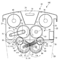
- FIG. 1 is a perspective view showing a structure of a packaging device for a waste container according to an embodiment of the present invention.
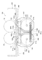
- FIG. 2 is a side view showing the internal structure of the packaging device for waste container according to the one embodiment.
- FIG. 3 is a perspective view of the structure of the packaging device for a waste container according to the one embodiment, as viewed obliquely from below.
- FIG. 4 is a perspective view showing another aspect of the friction roller.
- FIG. 5 is a cross-sectional view of the main part showing a gap between the opening of the housing and the peripheral surface of the friction roller.
- FIG. 6 is a diagram for explaining the operation of the packaging device for a waste container according to the one embodiment.
- FIG. 1 is a perspective view showing a structure of a packaging device for a waste container according to an embodiment of the present invention.
- FIG. 2 is a side view showing the internal structure of the packaging device for waste container according to the one embodiment.
- FIG. 3 is a perspective view of the structure of the
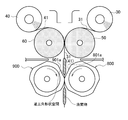
- FIG. 7 is a front view showing a main part of a packaging device for a waste container according to another embodiment of the present invention.
- FIG. 8 is a perspective view for explaining the configuration of the housing of the packaging device for a waste container according to the other embodiment.
- FIG. 9 is a perspective view for explaining a friction roller of the packaging device for a waste container according to another embodiment.
- FIG. 10 is a front view for explaining a friction roller of the packaging device for a waste container according to the other embodiment.
- FIG. 11 is a diagram for explaining the operation of the packaging device for waste container according to the other embodiment.
- FIG. 1 is a perspective view showing the structure of a waste container device package device 10 used in a waste container device 100 according to an embodiment of the present invention, and FIG. It is the side view which showed the internal structure.
- FIG. 3 is a perspective view of the waste container device 10 as viewed obliquely from below.
- the package device 10 for waste storage device of the present embodiment includes a frame member 20, film supply rollers 30, 40, waste sealing rollers 50, 60, a motor (drive unit) 70, and It has friction rollers 80 and 90.
- the frame member 20 only needs to be able to rotatably support the film supply rollers 30 and 40 and the waste sealing rollers 50 and 60, and the structure and shape thereof are not limited.
- a front plate portion 21, a back plate portion 22, and two opposing side plate portions 23, 23 are used, and between the opposed side plate portions 23, 23.
- the rollers 30 to 60 are arranged so as to be rotatable.
- the package device 10 for the waste container of the present embodiment is detachably mounted on the top of the bottomed waste container 120 at the top opening.
- An input port 24 is formed at an arbitrary position of the frame member 20, for example, the upper surface.
- a lower end provided at the lower portion of the frame member 20. It is accommodated in the waste accommodating part 120 through the opening 25.
- the insertion port 24 should just be provided so that a waste material can be sent in between the said film supply rollers 30 and 40,
- the formation position and structure are not limited.
- the film supply rollers 30 and 40 are spanned between the side plate portions 23 and 23 of the frame member 20 as described above, and are arranged opposite to each other in parallel with a predetermined distance from each other. It is provided so that it can pass between the film supply rollers 30 and 40 to perform.
- the film supply rollers 30 and 40 supply a film for sealing the waste put between them, and films 31 and 41 having a predetermined length and a predetermined width are wound around the film supply rollers 30 and 40.
- the type and material of the films 31 and 41 are not limited. However, since the films 31 and 41 are sealed so as to sandwich the waste, the films 31 and 41 need to have a property of being in close contact when the opposing film surfaces are joined.
- a plastic film may be used to adhere to each other by electrostatic action, or as at least one of the films 31 and 41, preferably as both films, a film having an adhesive layer formed at least on the side edge (Adhesive film) can also be used.
- Adhesive film By using such an adhesive film, the adhesion between the films 31 and 41 can be enhanced.
- one film 31 and the other film 41 are both adhesive films. Note that, as described above, for example, by providing the adhesive layer on at least the side edge of one of the films 31 and 41, waste can be sealed between the two, but the drawing direction of the films 31 and 41 ( It is also possible to provide a line along the width direction at predetermined intervals in the traveling direction). Thus, the front and rear positions of the films 31 and 41 with the waste sandwiched between them can be brought into close contact with each other, and the waste can be more reliably sealed.
- the adhesive layer is preferably formed on the entire surface of at least one of the opposing surfaces of the films 31 and 41, and more preferably formed on the entire surface of both of the opposing surfaces.
- the waste enclosing rollers 50 and 60 are located between the side plate portions 23 and 23 of the frame member 20, and are separated from the film supply rollers 30 and 40 in a direction in which the films 31 and 41 are pulled out, and are substantially parallel, that is, In the embodiment, the film supply rollers 30 and 40 are spaced apart from each other and are substantially parallel to each other.
- the waste enclosing rollers 50 and 60 are arranged to face each other in parallel so that their peripheral surfaces are in contact with each other through the films 31 and 41 passing between them.
- the waste enclosing rollers 50 and 60 sandwich the films 31 and 41 therebetween and face each other inward, that is, one waste enclosing roller 50 is counterclockwise in the side view of FIG. By rotating the object enclosing roller 60 in the clockwise direction, the films 31 and 41 are pulled out from the film supply rollers 30 and 40, and the films 31 and 41 are brought into close contact with each other.
- the waste enclosing rollers 50 and 60 only need to perform such functions. However, since the waste enclosing rollers 50 and 60 are arranged with their peripheral surfaces close to each other as described above, it is necessary to absorb the thickness of the waste passing between them. Accordingly, it is necessary to use at least one of the waste sealing rollers 50 and 60 whose peripheral surface shape is elastically deformed as the waste passes.
- both the waste enclosing rollers 50 and 60 are formed by mounting cylindrical members 52 and 62 formed of sponge on the rotating shafts 51 and 61, respectively.
- the cylindrical members 52 and 62 are not limited to sponges, and rubber may be used, or a predetermined width near the center may be a sponge and both sides thereof may be made of rubber. When all are made of sponge, the pulling force of the films 31 and 41 is reduced, so it is preferable to use rubber for a part.
- the present invention is characterized in that friction rollers 80 and 90, which will be described later, are provided. Since the pulling force of the friction rollers 80 and 90 acts, the pulling force of the waste enclosing rollers 50 and 60 themselves. Is smaller than the conventional one.
- the cylindrical members 52, 62 are all made of sponge as the waste sealing rollers 50, 60, thereby reducing the cost.
- the cylindrical members 52 and 62 are made of sponge, there is almost no drawing force of the film, but the film is drawn by the action of the friction rollers 80 and 90. This point is of course the same in other embodiments described later.
- the cylindrical members 52 and 62 are elastically deformed with the passage of the waste such as the waste, and thus fit the surface shape of the waste or the like. Accordingly, it is possible to reduce the bulk by compressing the waste and the like, and with the deaeration action that reduces the amount of air remaining between the films 31 and 41, the waste storage efficiency in the waste storage unit 120 is improved. Can be made.
- the motor 70 is disposed in the gap between the front plate portion 21 in the frame member 20 and the waste enclosing roller 60.
- a drive belt 71 is wound around the output shaft of the motor 70, a rotation output portion such as a gear, and the rotation shaft 61 of the waste enclosing roller 60, and at both ends of the waste enclosing rollers 50 and 60, respectively.
- the arrangement position of the motor 70 is not limited, and may be arranged in an empty space in the frame member 20. Further, depending on the position where the motor 70 is disposed, the rotation output portion of the motor 70 may be directly connected to one of the waste sealing rollers 50 and 60 without using the drive belt 71.
- the power source of the motor 70 is arbitrary, but in this embodiment, a battery disposed in the battery box 72 is used. In addition, it is also possible to supply from the outlet as a power source for driving the motor 70. However, if the battery is used as the power source of the motor 70, the battery 70 can be used even when there is no outlet around the installation site of the package device 10 for the waste container, and it is convenient to carry.
- the side plate part 23 is provided with a detection means 73 such as an optical sensor (see FIG. 2).
- a detection means 73 it is detected whether or not the waste to be processed passes between the film supply rollers 30 and 40 and is positioned between the films 31 and 41.
- the detection means 73 detects the waste, it outputs a drive signal to the motor 70 to rotate the waste sealing rollers 50 and 60.
- the detection means it is possible to use a weight sensor that detects whether or not the weight of the waste acts on the waste sealing rollers 50 and 60.
- a weight sensor that detects whether or not the weight of the waste acts on the waste sealing rollers 50 and 60.
- the detection means 73 such as an optical sensor is used, it can be automatically processed by simply putting in waste.
- a switch such as a push button is provided, and the motor 70 is operated by operating the switch. It can also be set as the structure which drives.
- the friction rollers 80 and 90 constituting the main part of this embodiment will be described.
- the friction rollers 80 and 90 are disposed below the waste enclosing rollers 50 and 60 so that the films 31 and 41 sealed with the waste passing through the waste enclosing rollers 50 and 60 can be pulled downward.
- the friction rollers 80 and 90 are arranged to face each other in parallel so that their peripheral surfaces are in contact with each other through the films 31 and 41 passing between them.
- the friction rollers 80 and 90 sandwich the films 31 and 41 therebetween and face each other inward, that is, in the side view of FIG. 2, one friction roller 80 is counterclockwise and the other friction roller 90 is clockwise. By rotating, the films 31, 41 are pulled out.
- substantially cylindrical housings 81 and 91 having an approximately elliptical cross section are located between the side plate portions 23 and 23 of the frame member 20 and below the two waste sealing rollers 50 and 60. It is spaced apart and stretched substantially in parallel.
- Shaft portions 82 and 92 are provided integrally with the housings 81 and 91 in the vicinity of the upper portions of the housings 81 and 91. As shown in FIGS. 2 and 3, the shaft portions 82 and 92 have both longitudinal ends. Are supported by a total of four support members 26 fixed along the lower edges of the side plate portions 23, 23 of the frame member 20 and near the front plate portion 21 and the back plate portion 22, respectively.
- the friction rollers 80 and 90 are rotatably provided by shaft portions 84 and 94 at substantially the center in the longitudinal direction of the housings 81 and 91, and at least a part of the outer periphery of each of the friction rollers 80 and 90, at least the friction rollers 80 and 90.
- the side where the two come into contact with each other is provided so as to face outward from an opening 83, 93 provided substantially at the center in the longitudinal direction of the housing 81, 91.
- the shaft portions 84 and 94 of the friction rollers 80 and 90 are located below the shaft portions 82 and 92 of the housings 81 and 91, the housings 81 and 91 rotate around the shaft portions 82 and 92.
- the friction rollers 80 and 90 can be moved toward and away from each other as indicated by arrows in FIG.
- a spring (coil spring) 87 is stretched between the end portions of the shaft portions 84 and 94 that support the friction rollers 80 and 90 and the support member 26.
- the elastic member is provided between the end portion of the shaft portion 94 on the near side of the drawing and the support member 26 on the near side of the drawing provided near the back plate portion 22.
- the spring 87 is slanted and the spring 87 is slanted between the end of the shaft 84 on the back side of the figure and the support member 26 on the back side of the figure provided near the front plate 21.
- the housings 81 and 91 are rotatably supported around the shaft portions 82 and 92. Since the friction rollers 80 and 90 can be moved closer to each other by rotating the housings 81 and 91, when a hard friction roller 80 or 90 is used, a waste having a predetermined thickness can pass through. It is.
- the friction rollers 80 and 90 are preferably hard resin rollers whose peripheral surfaces 85 and 95 have a high friction coefficient, for example, in order to increase the pulling force for pulling the films 31 and 41 downward. As the frictional force of the friction rollers 80 and 90 increases, the pulling force increases.
- a material having a high friction coefficient may be used for the surfaces of the peripheral surfaces 85 and 95, or another member having a high friction coefficient may be mounted on the peripheral surfaces 85 and 95.
- O-rings 86 and 96 made of hard rubber can be provided in contact with each other at corresponding positions in the circumferential direction of the peripheral surfaces 85 and 95 of the friction rollers 80 and 90.
- the O-rings 86 and 96 are not limited to two rows as shown in the drawings, and other friction members can be used.
- the widths X of the openings 83 and 93 of the housings 81 and 91 and the widths of the friction rollers 80 and 90 at which at least the portions in contact with the films 31 and 41 are exposed to the outside from the openings 83 and 93 are as follows.
- the film 31 or 41 is preferably configured to be narrower than the width.
- the gap G between the peripheral surfaces 85 and 95 of the friction rollers 80 and 90 and the housings 81 and 91 is less than the thickness of the waste. Thereby, the effect of preventing the waste sent out by the friction rollers 80 and 90 from being caught in the friction rollers 80 and 90 is increased.
- the length of the gap G is preferably set to 5 mm or less for paper diapers and sanitary napkins.
- gears 53 and 63 (hereinafter referred to as “first gears 53 and 63” for convenience) provided at one end in the longitudinal direction of the waste sealing rollers 50 and 60 are used.
- Second gears 112 and 112 that mesh with each other and third gears 113 and 113 that are disposed on the same shaft portions 82 and 92 as the second gears 112 and 112 are provided.
- fourth gears 114 and 114 meshing with the third gears 113 and 113 are provided on the shaft portions 84 and 94 of the friction rollers 80 and 90, respectively, and when the rotation is transmitted to the fourth gears 114 and 114, they are synchronized therewith.
- the friction rollers 80 and 90 are rotated.
- the gear ratio between the first gears 53 and 63 and the second gears 112 and 112 is 2: 1, and the second gears 112 and 112, the third gears 113 and 113, and the fourth gears 114 and 114
- the gear ratio is 1: 1: 1.
- the gear ratio of each of the gears 111 to 114 is not limited to this.
- the rotational speed of the friction rollers 80 and 90 is equal to or higher than the rotational speed of the waste enclosing rollers 50 and 60. Preferably there is.
- the friction rollers 80 and 90 described above are rotated by using the rotational drive of the waste enclosing rollers 50 and 60.
- a power source such as a motor, a gear, etc., different from the waste enclosing rollers 50 and 60 is used.
- a rotation transmission mechanism such as a driving belt can be provided.
- the package apparatus 10 for waste container includes the frame member 20 mounted on the upper part of the waste container 120, and the whole is used as the waste container 100.
- the films 31 and 41 of the film supply rollers 30 and 40 are sandwiched between the waste sealing rollers 50 and 60 and the friction rollers 80 and 90.
- the detection means 73 such as an optical sensor detects the waste and outputs a drive signal to the motor 70.
- the motor 70 receives the drive signal, the motor 70 starts rotating.
- the rotation of the motor 70 is transmitted from the drive belt 71 to the waste enclosing rollers 50 and 60, and the waste enclosing rollers 50 and 60 start rotating in synchronization.
- the films 31 and 41 are joined together by being brought into close contact with the two waste enclosing rollers 50 and 60.
- the films 31 and 41 are bonded to each other by passing between the waste sealing rollers 50 and 60.
- the thrown-in waste passes between the waste enclosing rollers 50 and 60.
- the cylindrical members 52 and 62 of the waste enclosing rollers 50 and 60 are in the shape of waste. Therefore, the films 31 and 41 are brought into close contact with the periphery (surface) of the waste while deaeration.
- the films 31 and 41 are again fed by the waste enclosing rollers 50 and 60. They are directly joined together by the adhesive layer.
- the waste is sealed by the films 31 and 41 and stored in the waste storage unit 120 in this state. Even when waste is input again, the above-described operation is repeated, and the waste is sealed one after another. Accordingly, leakage of odor to the outside is prevented.
- the waste sealing rollers 50 and 60 are in contact with each other in a normal state even when only the side edges of the films 31 and 41 are in close contact with each other, the odors are exposed to the outside. There is little leakage.
- the front and rear positions sandwiching the waste are also in close contact.
- the motor 70 is set to stop when a predetermined time elapses after the detection unit 73 no longer detects waste.
- the films 31 and 41 sealed with the two waste sealing rollers 50 and 60 are pulled downward by the two friction rollers 80 and 90 that are driven to rotate downward, as in the conventional case. It is possible to prevent the waste from being caught in the waste sealing rollers 50 and 60.
- the housings 81, 91 rotate in the direction of separating outwardly about the shaft portions 82, 92. Thereby, the waste of predetermined thickness can pass through.
- the widths of the openings 83 and 93 of the housings 81 and 91 are configured to be narrower than the film width, the effect of preventing waste from being caught in the friction rollers 80 and 90 is increased.
- the gap G between the peripheral surfaces 85, 95 of the friction rollers 80, 90 and the housings 81, 91 is configured to be less than the thickness of the waste, so that the waste is caught in the friction rollers 80, 90. The effect of preventing becomes greater.
- the waste-sealed films 31 and 41 are configured not to be caught in any of the waste sealing rollers 50 and 60 and the friction rollers 80 and 90. More waste can be pushed into the waste storage unit 120, and waste storage efficiency can be increased.
- the waste can be processed until each of the films 31 and 41 is consumed, but the films 31 and 41 can be cut and disposed in the middle according to the amount of the waste container 120.
- FIG. 7 to 11 are views showing a main part of a package apparatus 10A for a waste container according to another embodiment of the present invention.
- the present embodiment is different from the above-described embodiment in the mechanism for drawing the waste composed of the friction rollers 800, 900, the housings 810, 910 and the like downward.
- the housings 810 and 910 have two end wall portions 811, 811 or 911 and 911 that face each other at a predetermined interval, and are provided on the upper portions 811a and 911a.
- the shaft portions 820 and 920 are pivotally supported in shaft holes formed in the support member 260 provided along the lower edges of the side plate portions 230 and 230 of the frame member 200 as in the above embodiment.
- the friction rollers 800 and 900 are formed in a space 815 between the end wall portions 811 and 811 of the housing 810 and between the end wall portions 911 and 911 of the housing 910. They are respectively arranged, are pivotally supported on the respective end wall portions 811 and 911 via shaft portions 840 and 940, and are provided to be freely rotatable.
- the friction rollers 800 and 900 include two roller portions 801, 802 or 901, 902 along the axial direction, respectively.
- each of the roller portions 801, 802, 901, 902 is not circular in outer peripheral surface shape, and includes flat surfaces 801a, 802a, 901a, 902a on at least a part of the outer peripheral surface.
- flat surfaces 801a and 802a of one friction roller 800 and the flat surfaces 901a and 902a of the other friction roller 900 are adjusted so that they always face each other when the friction rollers 800 and 900 rotate. (See FIG. 7)).
- flat surfaces 801a, 802a, 901a, 902a are formed on four surfaces at equal intervals in the circumferential direction, and the space between adjacent flat surfaces is a curved surface (see FIG. 10).
- Friction members for increasing the frictional force for example, rubbers 803, 804, 903, 904 such as urethane rubber, are mounted in the circumferential direction on the outer peripheral surfaces of the roller portions 801, 802, 901, 902 of the friction rollers 800, 900.
- the friction rollers 800 and 900 have a configuration in which the outer peripheral length of each of the roller portions 801, 802, 901, and 902 with the rubber 803, 804, 903, and 904 is longer than the outer peripheral length of the waste enclosing rollers 50 and 60.
- the films 31 and 41 between the waste sealing rollers 50 and 60 and the friction rollers 800 and 900 are always provided on the films 31 and 41. Since the predetermined tension is applied, the entanglement of the films 31 and 41 with the waste sealing rollers 50 and 60 is further reduced.
- the second gears 112 and 112 mesh with the first gears 53 and 63 provided at one end in the longitudinal direction of the waste sealing rollers 50 and 60, and the second gears 112 and 112 are engaged. Is engaged with the fourth gears 114 and 114 provided on the shaft portions 840 and 940 of the friction rollers 800 and 900, and the rotation is transmitted.
- the first gears 53 and 63 and the fourth gears 114 and 114 have the same diameter. Thereby, the housings 800 and 900 are easily opened to the left and right.
- the basic operation of this embodiment is exactly the same as that of the above embodiment.
- the films 31 and 41 are in close contact with each other. Further, the films 31 and 41 are drawn downward by the friction rollers 800 and 900.
- the outer peripheral length of the friction rollers 800 and 900 (corresponding to the outer peripheral length of the rubbers 803, 804, 903, and 904 in this embodiment) is the outer peripheral length of the waste enclosing rollers 50 and 60. For this reason, the distance between the two is always kept at a predetermined tension.
- the housing 810 When passing between a pair of friction rollers 800, 900 (in this embodiment, between one rubber 803, 804 and the other rubber, 903, 904), depending on the thickness of the waste, the housing 810, Since 910 rotates about the shafts 820 and 920 in the direction away from each other (outward), it can pass between the pair of friction rollers 800 and 900.
- a rotation control member that controls the rotation of one housing 810 (and one friction roller 800) and the other housing 910 (and the other friction roller 900) is provided.
- the rotation control member includes one arm 810 a that rotates integrally with one housing 810 and the other arm 910 a that rotates together with the other housing 910. .
- a pin 810b is provided near the tip of one arm 810a, and a long hole 910b extending in the longitudinal direction is formed closer to the tip than the center of the other arm 910a.
- the pin 810b is inserted into the elongated hole 910b and is provided so as to be movable along the elongated hole 910b.
- the width of the long hole 910b is set to be approximately the same as the diameter of the pin 810b.
- Engaging projections 811b and 911b are provided near the lower end of the end wall portion 811 of one housing 810 and near the lower end of the end wall portion 911 of the other housing 910, respectively, and between the engaging projections 811b and 911b. Both ends of the coil spring 850 are engaged, and one housing 810 and the other housing 910 are always urged in the approaching direction.
- the pin 810b of one arm 810a is connected to the other arm 910a. Since the inner wall of the long hole 910b is pressed downward, one housing 810 (and one friction roller 800) and the other housing 910 (and the other friction roller 900) have a central portion between them. As a reference, the coil spring 850 rotates outwardly and evenly against the elastic force of the coil spring 850. When the rotation control member is not provided, there is a bias that one housing 810 (and one friction roller 800) and the other housing 910 (and the other friction roller 900) rotate in the same direction.
Landscapes
- Engineering & Computer Science (AREA)
- Mechanical Engineering (AREA)
- Refuse Receptacles (AREA)
- Containers And Plastic Fillers For Packaging (AREA)
Abstract
Description
図1は、本発明の一の実施形態に係る廃棄物収容装置100に用いた廃棄物収容装置用パッケージ装置10の構造を示す斜視図であり、図2は廃棄物収容装置用パッケージ装置10の内部構造を示した側面図である。図3は廃棄物収容装置用パッケージ装置10を斜め下側から視た斜視図である。これらの図に示したように、本実施形態の廃棄物収容装置用パッケージ装置10は、枠部材20、フィルム供給ローラ30,40、廃棄物封入用ローラ50,60、モータ(駆動部)70及びフリクションローラ80,90を有して構成される。
20 枠部材
21 正面板部
22 背面板部
23 側板部
24 投入口
25 下端開口部
26 支持部材
30,40 フィルム供給ローラ
31,41 フィルム
50,60 廃棄物封入用ローラ
51,61 回転軸
52,62 筒状部材
53,63 ギヤ(第1ギヤ)
70 モータ(駆動部)
71 駆動ベルト
80,90,800,900 フリクションローラ
81,91,810,910 ハウジング
82,92,820,920 軸部
83,93 開口部
84,94 軸部
85,95 周面
86,96 Oリング
87 バネ
100 廃棄物収容装置
112 第2ギヤ
113 第3ギヤ
114 第4ギヤ
120 廃棄物収容部
Claims (13)
- 廃棄物を収容する廃棄物収容部の上部に配設され、前記廃棄物を密封して前記廃棄物収容部内に収容する廃棄物収容装置用パッケージ装置であって、
前記廃棄物を投入するための投入口が形成された枠部材と、前記枠部材内に、所定間隔離間して配置される2本のフィルム供給ローラと、前記枠部材内に設けられ、前記各ィルム供給ローラから引き出される各フィルムを介して周面が接するように配置され、かつ少なくとも一方が廃棄物の形状に沿って弾性変形する周面を備えた2本の廃棄物封入用ローラと、前記各廃棄物封入用ローラを回転させる駆動部とを具備すると共に、
前記2本の廃棄物封入用ローラの間を通過した廃棄物を2枚のフィルム間で密封した状態で下方へ引き込むように回転駆動する2本のフリクションローラが、前記2本の廃棄物封入用ローラの下方に設けられていることを特徴とする廃棄物収容装置用パッケージ装置。 - 前記2本のフリクションローラは、前記2本の廃棄物封入用ローラの下方に配置したハウジング内で回転可能に設けられ、かつ前記各フリクションローラのうちの少なくともフィルムに接する部位が前記各ハウジングに形成した開口部から外側へ露出する構成である請求項1記載の廃棄物収容装置用パッケージ装置。
- 前記各ハウジングの前記各開口部の幅が前記フィルム幅より狭く構成されると共に、前記各フリクションローラの周面と各ハウジングの開口部との隙間が廃棄物の厚さ未満に構成されている請求項2記載の廃棄物収容装置用パッケージ装置。
- 前記各フリクションローラの周面と各ハウジングの開口部との隙間が5mm以下である請求項3記載の廃棄物収容装置用パッケージ装置。
- 前記各フリクションローラを支持する各ハウジングが、弾性部材により常態において互いに接近方向に付勢されており、前記フリクションローラを離間させる方向に負荷が働いた場合には、前記フリクションローラと共に各ハウジングが外方に回動する構成である請求項1記載の廃棄物収容装置用パッケージ装置。
- 前記各ハウジングは、前記フリクションローラを離間させる方向に負荷が働いた場合の回動を制御する回動制御制部材を備えている請求項5記載の廃棄物収容装置用パッケージ装置。
- 前記各ハウジングは、上部を中心として回動可能に設けられ、
前記回動制御部材は、一方のハウジングに設けられた一方のアームと、他方のハウジングに設けられた他方のアームとを有してなり、一方のアームに形成されたピンが他方のアームに形成された長穴に係合しており、
前記各ハウジングと共に各アームが回動することにより、一方のアームのピンが他方のアームの長穴の内壁を押圧し、各ハウジング間の中心部を基準として、それぞれ外方に均等に回動する構成である請求項6記載の廃棄物収容装置用パッケージ装置。 - 前記各フリクションローラは、外周面の少なくとも一部に平坦面を有する形状で形成され、かつ、一方のフリクションローラの平坦面と他方のフリクションローラの平坦面とは、回転した際に正対面するように設けられる請求項1記載の廃棄物収容装置用パッケージ装置。
- 前記フリクションローラの外周長が、前記廃棄物封入用ローラの外周長よりも長い請求項1記載の廃棄物収容装置用パッケージ装置。
- 前記各フリクションローラが、硬質素材から形成されている請求項1記載の廃棄物収容装置用パッケージ装置。
- 前記各フリクションローラの周面に、摩擦部材が設けられている請求項10記載の廃棄物収容装置用パッケージ装置。
- 前記2本のフリクションローラの回転速度が前記2本の廃棄物封入用ローラの回転速度と同じかそれ以上である請求項1記載の廃棄物収容装置用パッケージ装置。
- 請求項1~12のいずれか1に記載の廃棄物収容装置用パッケージ装置が、廃棄物を収容する廃棄物収容部の上部に配設されていることを特徴とする廃棄物収容装置。
Priority Applications (5)
| Application Number | Priority Date | Filing Date | Title |
|---|---|---|---|
| US13/380,062 US9079710B2 (en) | 2009-06-22 | 2010-06-22 | Packaging device for waste storage device and waste storage device |
| JP2011519898A JP5713353B2 (ja) | 2009-06-22 | 2010-06-22 | 廃棄物収容装置用パッケージ装置及び廃棄物収容装置 |
| AU2010263654A AU2010263654C1 (en) | 2009-06-22 | 2010-06-22 | Packaging device for waste containing device, and waste containing device |
| EP10792081.1A EP2447192B1 (en) | 2009-06-22 | 2010-06-22 | Packaging device for waste containing device, and waste containing device |
| KR1020127001508A KR101318725B1 (ko) | 2009-06-22 | 2010-06-22 | 폐기물 수용 장치용 패키지 장치 및 폐기물 수용 장치 |
Applications Claiming Priority (2)
| Application Number | Priority Date | Filing Date | Title |
|---|---|---|---|
| JP2009147515 | 2009-06-22 | ||
| JP2009-147515 | 2009-06-22 |
Publications (1)
| Publication Number | Publication Date |
|---|---|
| WO2010150763A1 true WO2010150763A1 (ja) | 2010-12-29 |
Family
ID=43386532
Family Applications (1)
| Application Number | Title | Priority Date | Filing Date |
|---|---|---|---|
| PCT/JP2010/060506 Ceased WO2010150763A1 (ja) | 2009-06-22 | 2010-06-22 | 廃棄物収容装置用パッケージ装置及び廃棄物収容装置 |
Country Status (6)
| Country | Link |
|---|---|
| US (1) | US9079710B2 (ja) |
| EP (1) | EP2447192B1 (ja) |
| JP (1) | JP5713353B2 (ja) |
| KR (1) | KR101318725B1 (ja) |
| AU (1) | AU2010263654C1 (ja) |
| WO (1) | WO2010150763A1 (ja) |
Cited By (5)
| Publication number | Priority date | Publication date | Assignee | Title |
|---|---|---|---|---|
| JP2019038588A (ja) * | 2017-08-25 | 2019-03-14 | 大森機械工業株式会社 | ピロー包装機 |
| KR20190093472A (ko) * | 2018-02-01 | 2019-08-09 | 주식회사 공의 | 생리대 수거함 |
| WO2021117469A1 (ja) * | 2019-12-13 | 2021-06-17 | Phcホールディングス株式会社 | 薬剤供給装置 |
| WO2023074706A1 (ja) | 2021-10-26 | 2023-05-04 | 共立製薬株式会社 | 包装装置及び廃棄物収容装置 |
| JP2024518662A (ja) * | 2021-05-26 | 2024-05-01 | ソン パク,ジョン | 廃棄物収集箱の廃棄物密封不良防止構造 |
Families Citing this family (15)
| Publication number | Priority date | Publication date | Assignee | Title |
|---|---|---|---|---|
| CN104071500A (zh) * | 2014-06-30 | 2014-10-01 | 无锡市崇安区科技创业服务中心 | 一种电池回收箱 |
| DE102014010264A1 (de) * | 2014-07-11 | 2016-01-14 | Rotho Babydesign Gmbh | Vorrichtung sowie Verpackungsverfahren zum portionsweisen Verschließen von Exkrementen, Verbandsmaterialien, Damenhygieneartikeln oder dergleichen in Verpackungen |
| KR101971379B1 (ko) * | 2014-09-03 | 2019-04-22 | 다이세이 라믹 가부시키가이샤 | 액상 피포장물의 충전 포장방법 및 충전 포장기 |
| US20180065802A1 (en) * | 2015-03-22 | 2018-03-08 | Rotho Babydesign Gmbh | Method for converting secondary biological material into reusable energy and for storing said material, encasing method, and encasing device and encasing material herefor |
| US11154161B2 (en) | 2017-12-05 | 2021-10-26 | Robert Almblad | Automated food cooking system |
| WO2019113140A1 (en) | 2017-12-06 | 2019-06-13 | Robert Almblad | Food dispensing module for a delaminating food dispensing system |
| US11344153B2 (en) | 2018-03-04 | 2022-05-31 | Robert Almblad | Vertical cooking system |
| KR102140934B1 (ko) * | 2018-12-11 | 2020-08-05 | 주식회사 아이멧 | 폐 위생용품 밀봉장치 |
| US11673697B2 (en) | 2019-03-27 | 2023-06-13 | Robert Almblad | Laminated food dispensing module for use with automatic grill system |
| CN110668040B (zh) * | 2019-10-14 | 2021-10-01 | 赵嘉义 | 一种环保工程固液分离垃圾箱 |
| US11974703B2 (en) * | 2020-01-04 | 2024-05-07 | Kohler Co. | Liner toilet |
| IT202100031247A1 (it) * | 2021-12-14 | 2023-06-14 | Lucio Sighinolfi | Raccoglitore automatico di prodotti laminari flessibili e relativo procedimento di raccolta automatica |
| JP7618306B2 (ja) | 2022-10-05 | 2025-01-21 | 共立製薬株式会社 | トイレ管理装置及びコンピュータプログラム |
| KR102791037B1 (ko) * | 2022-11-17 | 2025-04-02 | 성신여자대학교 연구 산학협력단 | 가정용 쓰레기 분리수거장치 |
| CN117163506A (zh) * | 2023-09-11 | 2023-12-05 | 光子机器人(宁波)有限公司 | 一种用于智能打包坐便器的塑料袋下拉装置及智能坐便器 |
Citations (3)
| Publication number | Priority date | Publication date | Assignee | Title |
|---|---|---|---|---|
| JPS61217309A (ja) * | 1985-03-20 | 1986-09-26 | 株式会社 東京商会 | 薬剤包装装置 |
| WO2005037684A1 (ja) * | 2003-10-16 | 2005-04-28 | Kyoritsu Seiyaku Corporation | パッケージ装置及びゴミ箱 |
| JP2006321516A (ja) * | 2005-05-18 | 2006-11-30 | Tosho Inc | 薬剤分包機 |
Family Cites Families (12)
| Publication number | Priority date | Publication date | Assignee | Title |
|---|---|---|---|---|
| US2616232A (en) * | 1947-10-21 | 1952-11-04 | Sterling Drug Inc | Method and apparatus for manufacture of ampoules and other containers |
| US3596428A (en) * | 1968-10-07 | 1971-08-03 | American Maize Prod Co | Packaging process and apparatus |
| US3641737A (en) * | 1969-01-23 | 1972-02-15 | Eurosicma Soc Italiana Costruz | Packaging machine for bags to be filled with liquids, powders or granular products |
| US4215524A (en) * | 1979-01-29 | 1980-08-05 | C. R. Bard, Inc. | Membrane packaging machine |
| GB9121420D0 (en) * | 1991-10-09 | 1991-11-20 | Ag Patents Ltd | Manufacturing infusion packages |
| KR970008858B1 (ko) * | 1994-10-08 | 1997-05-30 | 이한우 | 자기부상 무부하 이중연사장치 |
| EP0861191B1 (fr) * | 1995-11-17 | 2000-05-24 | Captiva Holding | Dispositif pour collecter et confiner les dechets hospitaliers et menagers |
| NL1006482C2 (nl) * | 1997-07-04 | 1999-01-25 | Gideon Noordenbos | Inrichting voor het hygiënisch verpakken van gebruikte voorwerpen. |
| IL123041A (en) * | 1998-01-25 | 2001-05-20 | Nova Tek Technologies Ltd | Apparatus and method for making pouches |
| GB9908206D0 (en) * | 1999-04-09 | 1999-06-02 | Sangenic International Limited | Waste storage device |
| CA2509689A1 (en) * | 2002-12-13 | 2004-07-01 | Sanford Redmond, Inc. | Machine to make e-z open pouch with flap and bulge |
| JP4195912B2 (ja) * | 2003-10-28 | 2008-12-17 | 株式会社スミロン | 発臭性廃棄物の封止基材及び発臭性廃棄物の封止方法 |
-
2010
- 2010-06-22 KR KR1020127001508A patent/KR101318725B1/ko active Active
- 2010-06-22 AU AU2010263654A patent/AU2010263654C1/en active Active
- 2010-06-22 EP EP10792081.1A patent/EP2447192B1/en active Active
- 2010-06-22 WO PCT/JP2010/060506 patent/WO2010150763A1/ja not_active Ceased
- 2010-06-22 JP JP2011519898A patent/JP5713353B2/ja active Active
- 2010-06-22 US US13/380,062 patent/US9079710B2/en active Active
Patent Citations (4)
| Publication number | Priority date | Publication date | Assignee | Title |
|---|---|---|---|---|
| JPS61217309A (ja) * | 1985-03-20 | 1986-09-26 | 株式会社 東京商会 | 薬剤包装装置 |
| WO2005037684A1 (ja) * | 2003-10-16 | 2005-04-28 | Kyoritsu Seiyaku Corporation | パッケージ装置及びゴミ箱 |
| JP3923068B2 (ja) | 2003-10-16 | 2007-05-30 | 共立製薬株式会社 | ゴミ箱 |
| JP2006321516A (ja) * | 2005-05-18 | 2006-11-30 | Tosho Inc | 薬剤分包機 |
Cited By (11)
| Publication number | Priority date | Publication date | Assignee | Title |
|---|---|---|---|---|
| JP2019038588A (ja) * | 2017-08-25 | 2019-03-14 | 大森機械工業株式会社 | ピロー包装機 |
| KR20190093472A (ko) * | 2018-02-01 | 2019-08-09 | 주식회사 공의 | 생리대 수거함 |
| KR102028276B1 (ko) | 2018-02-01 | 2019-11-04 | 주식회사 공의 | 생리대 수거함 |
| WO2021117469A1 (ja) * | 2019-12-13 | 2021-06-17 | Phcホールディングス株式会社 | 薬剤供給装置 |
| JPWO2021117469A1 (ja) * | 2019-12-13 | 2021-06-17 | ||
| JP7348958B2 (ja) | 2019-12-13 | 2023-09-21 | Phcホールディングス株式会社 | 薬剤供給装置 |
| US11801202B2 (en) | 2019-12-13 | 2023-10-31 | Phc Holdings Corporation | Medicine dispensing apparatus |
| JP2024518662A (ja) * | 2021-05-26 | 2024-05-01 | ソン パク,ジョン | 廃棄物収集箱の廃棄物密封不良防止構造 |
| JP7665259B2 (ja) | 2021-05-26 | 2025-04-21 | ソン パク,ジョン | 廃棄物収集箱の廃棄物密封構造 |
| WO2023074706A1 (ja) | 2021-10-26 | 2023-05-04 | 共立製薬株式会社 | 包装装置及び廃棄物収容装置 |
| KR20240095516A (ko) | 2021-10-26 | 2024-06-25 | 교리츠 세이야쿠 가부시키가이샤 | 포장 장치 및 폐기물 수용 장치 |
Also Published As
| Publication number | Publication date |
|---|---|
| AU2010263654C1 (en) | 2015-10-01 |
| KR101318725B1 (ko) | 2013-10-16 |
| JPWO2010150763A1 (ja) | 2012-12-10 |
| KR20120042847A (ko) | 2012-05-03 |
| US20120151882A1 (en) | 2012-06-21 |
| AU2010263654B2 (en) | 2015-07-02 |
| EP2447192A1 (en) | 2012-05-02 |
| JP5713353B2 (ja) | 2015-05-07 |
| EP2447192B1 (en) | 2020-11-11 |
| US9079710B2 (en) | 2015-07-14 |
| AU2010263654A1 (en) | 2012-02-02 |
| EP2447192A4 (en) | 2017-12-06 |
Similar Documents
| Publication | Publication Date | Title |
|---|---|---|
| JP5713353B2 (ja) | 廃棄物収容装置用パッケージ装置及び廃棄物収容装置 | |
| JP3923068B2 (ja) | ゴミ箱 | |
| JP5849372B2 (ja) | 医療用具封止装置 | |
| KR101705383B1 (ko) | 접합 장치 및 흡수성 물품의 제조 방법 | |
| US9164430B2 (en) | Developer container, developing cartridge, process cartridge and image forming apparatus | |
| JP5693678B2 (ja) | 現像剤収納容器、現像剤収納ユニット、プロセスカートリッジ、画像形成装置 | |
| CN101854900B (zh) | 用于吸收性物品的分配器 | |
| US10268143B2 (en) | Drive device and image forming apparatus incorporating the drive device | |
| KR20200071914A (ko) | 폐 위생용품 밀봉장치 | |
| JP2009051509A (ja) | 発臭性廃棄物の封止装置 | |
| WO2023074706A1 (ja) | 包装装置及び廃棄物収容装置 | |
| KR100773113B1 (ko) | 포장장치 | |
| KR20220003263A (ko) | 교체 카트리지가 적용된 오염물 개별밀폐장치 | |
| JP5339447B2 (ja) | 連続シート体の破断装置 | |
| JP7081249B2 (ja) | シート搬送装置及び画像形成装置 | |
| JP2025186034A (ja) | 廃棄物収容装置 | |
| JP3810693B2 (ja) | 貼合せ製品の一体化物の製造方法 | |
| CN109455331A (zh) | 一种包膜装置 | |
| JP2001048112A (ja) | チップ収集装置及びそれを用いた包装機 | |
| JP2015117101A (ja) | 廃棄物収容装置 | |
| JP2014218293A (ja) | フィルムカセット及びカセットケース | |
| JP2000168785A (ja) | ロール状内容物収納袋 | |
| JP2004166861A (ja) | 清掃具 |
Legal Events
| Date | Code | Title | Description |
|---|---|---|---|
| 121 | Ep: the epo has been informed by wipo that ep was designated in this application |
Ref document number: 10792081 Country of ref document: EP Kind code of ref document: A1 |
|
| WWE | Wipo information: entry into national phase |
Ref document number: 2011519898 Country of ref document: JP |
|
| NENP | Non-entry into the national phase |
Ref country code: DE |
|
| WWE | Wipo information: entry into national phase |
Ref document number: 2010263654 Country of ref document: AU |
|
| WWE | Wipo information: entry into national phase |
Ref document number: 2010792081 Country of ref document: EP |
|
| ENP | Entry into the national phase |
Ref document number: 20127001508 Country of ref document: KR Kind code of ref document: A |
|
| ENP | Entry into the national phase |
Ref document number: 2010263654 Country of ref document: AU Date of ref document: 20100622 Kind code of ref document: A |
|
| WWE | Wipo information: entry into national phase |
Ref document number: 13380062 Country of ref document: US |