WO2011001702A1 - 弁開閉時期制御装置 - Google Patents
弁開閉時期制御装置 Download PDFInfo
- Publication number
- WO2011001702A1 WO2011001702A1 PCT/JP2010/052075 JP2010052075W WO2011001702A1 WO 2011001702 A1 WO2011001702 A1 WO 2011001702A1 JP 2010052075 W JP2010052075 W JP 2010052075W WO 2011001702 A1 WO2011001702 A1 WO 2011001702A1
- Authority
- WO
- WIPO (PCT)
- Prior art keywords
- state
- fluid
- chamber
- phase
- restriction
- Prior art date
- Legal status (The legal status is an assumption and is not a legal conclusion. Google has not performed a legal analysis and makes no representation as to the accuracy of the status listed.)
- Ceased
Links
Images


Classifications
-
- F—MECHANICAL ENGINEERING; LIGHTING; HEATING; WEAPONS; BLASTING
- F01—MACHINES OR ENGINES IN GENERAL; ENGINE PLANTS IN GENERAL; STEAM ENGINES
- F01L—CYCLICALLY OPERATING VALVES FOR MACHINES OR ENGINES
- F01L1/00—Valve-gear or valve arrangements, e.g. lift-valve gear
- F01L1/34—Valve-gear or valve arrangements, e.g. lift-valve gear characterised by the provision of means for changing the timing of the valves without changing the duration of opening and without affecting the magnitude of the valve lift
- F01L1/344—Valve-gear or valve arrangements, e.g. lift-valve gear characterised by the provision of means for changing the timing of the valves without changing the duration of opening and without affecting the magnitude of the valve lift changing the angular relationship between crankshaft and camshaft, e.g. using helicoidal gear
- F01L1/3442—Valve-gear or valve arrangements, e.g. lift-valve gear characterised by the provision of means for changing the timing of the valves without changing the duration of opening and without affecting the magnitude of the valve lift changing the angular relationship between crankshaft and camshaft, e.g. using helicoidal gear using hydraulic chambers with variable volume to transmit the rotating force
- F01L2001/3445—Details relating to the hydraulic means for changing the angular relationship
- F01L2001/34453—Locking means between driving and driven members
- F01L2001/34459—Locking in multiple positions
-
- F—MECHANICAL ENGINEERING; LIGHTING; HEATING; WEAPONS; BLASTING
- F01—MACHINES OR ENGINES IN GENERAL; ENGINE PLANTS IN GENERAL; STEAM ENGINES
- F01L—CYCLICALLY OPERATING VALVES FOR MACHINES OR ENGINES
- F01L1/00—Valve-gear or valve arrangements, e.g. lift-valve gear
- F01L1/34—Valve-gear or valve arrangements, e.g. lift-valve gear characterised by the provision of means for changing the timing of the valves without changing the duration of opening and without affecting the magnitude of the valve lift
- F01L1/344—Valve-gear or valve arrangements, e.g. lift-valve gear characterised by the provision of means for changing the timing of the valves without changing the duration of opening and without affecting the magnitude of the valve lift changing the angular relationship between crankshaft and camshaft, e.g. using helicoidal gear
- F01L1/3442—Valve-gear or valve arrangements, e.g. lift-valve gear characterised by the provision of means for changing the timing of the valves without changing the duration of opening and without affecting the magnitude of the valve lift changing the angular relationship between crankshaft and camshaft, e.g. using helicoidal gear using hydraulic chambers with variable volume to transmit the rotating force
- F01L2001/3445—Details relating to the hydraulic means for changing the angular relationship
- F01L2001/34453—Locking means between driving and driven members
- F01L2001/34469—Lock movement parallel to camshaft axis
-
- F—MECHANICAL ENGINEERING; LIGHTING; HEATING; WEAPONS; BLASTING
- F01—MACHINES OR ENGINES IN GENERAL; ENGINE PLANTS IN GENERAL; STEAM ENGINES
- F01L—CYCLICALLY OPERATING VALVES FOR MACHINES OR ENGINES
- F01L1/00—Valve-gear or valve arrangements, e.g. lift-valve gear
- F01L1/34—Valve-gear or valve arrangements, e.g. lift-valve gear characterised by the provision of means for changing the timing of the valves without changing the duration of opening and without affecting the magnitude of the valve lift
- F01L1/344—Valve-gear or valve arrangements, e.g. lift-valve gear characterised by the provision of means for changing the timing of the valves without changing the duration of opening and without affecting the magnitude of the valve lift changing the angular relationship between crankshaft and camshaft, e.g. using helicoidal gear
- F01L1/3442—Valve-gear or valve arrangements, e.g. lift-valve gear characterised by the provision of means for changing the timing of the valves without changing the duration of opening and without affecting the magnitude of the valve lift changing the angular relationship between crankshaft and camshaft, e.g. using helicoidal gear using hydraulic chambers with variable volume to transmit the rotating force
- F01L2001/3445—Details relating to the hydraulic means for changing the angular relationship
- F01L2001/34453—Locking means between driving and driven members
- F01L2001/34476—Restrict range locking means
Definitions
- the present invention relates to a valve opening / closing timing control device that controls a relative rotation phase of a driven side rotating member with respect to a driving side rotating member that rotates in synchronization with a crankshaft of an internal combustion engine.
- a valve opening / closing timing control device in addition to a lock mechanism for maintaining the relative rotation phase of the driven side rotating member with respect to the driving side rotating member at a predetermined phase (lock phase), a regulating recess formed in the driven side rotating member, and the driving side rotation 2.
- a valve opening / closing timing control device includes a restricting mechanism that is disposed on a member and includes a restricting member that can be moved back and forth with respect to a restricting recess.
- the lock mechanism can be operated after the relative rotation phase of the driven-side rotating member with respect to the driving-side rotating member is regulated within a certain range, and thus there is an advantage that the locked state can be achieved more easily.
- valve opening / closing timing control device described in Patent Document 1 is configured to discharge the fluid from the advance chamber and the retard chamber when the relative rotation phase is not the lock phase when the engine is started.
- the driven-side rotating member can be positively rotated relative to the driving-side rotating member immediately after the engine is started, and the locked state is realized during the rotation.
- a dedicated switching valve 110 is provided to discharge the fluid from the advance chamber and the retard chamber immediately after the engine is started. For this reason, there exists a possibility of causing the fall of the mounting property of a valve opening / closing timing control apparatus, and the raise of cost.
- the locked state is realized when the engine is started, there is a possibility that the operation state cannot be quickly shifted. Therefore, a configuration that can realize the locked state before the engine is stopped is desirable.
- the lock mechanism that discharges and locks such a fluid is to be implemented when the engine is stopped, the fluid is discharged, while the rotational speeds of the driven-side rotating member and the driving-side rotating member also rapidly decrease. There was a possibility that the lock was not surely performed.
- the present invention realizes a locked state before the engine is stopped by controlling the restriction mechanism and the lock mechanism during engine operation, and provides a dedicated switching valve for controlling the restriction mechanism and the lock mechanism.
- An object of the present invention is to provide an unnecessary valve opening / closing timing control device.
- a first characteristic configuration of the valve timing control apparatus is a drive side rotary member that rotates synchronously with a crankshaft of an internal combustion engine, and is arranged coaxially with respect to the drive side rotary member.
- a driven-side rotating member that rotates in synchronization with a camshaft for opening and closing the valve, a fluid pressure chamber formed by the drive-side rotating member and the driven-side rotating member, and the fluid pressure chamber as an advance chamber and a retard chamber And arranged on at least one of the driving side rotating member and the driven side rotating member and the rotating member of the driving side rotating member or the driven side rotating member.
- a restricting member that can be moved back and forth with respect to one of the other rotating members and the other rotating member, and the restricting member enters, and the relative rotation phase of the driven rotating member with respect to the driving rotating member is changed.
- the most advanced phase Is arranged in one of the most retarded phase and a regulating recess for regulating the range from the most advanced angle phase to a predetermined phase between the most retarded angle phase and the one rotating member provided with the regulating member
- a locking member that can be moved back and forth with respect to the other rotating member, and the other rotating member, and the locking member enters and the relative rotation of the driven rotating member relative to the driving rotating member.
- a lock recess that locks the rotation phase to the predetermined phase, and a fluid that can supply the lock member with a fluid that releases the restriction by the restriction member, and a communication that cannot supply the fluid that releases the lock by the lock member to the restriction member.
- the restriction member is configured to switch the communication channel between communication and non-communication.
- the fluid for releasing the restriction by the restriction member can be supplied to the lock member, when the advance angle control is performed, a state where both the restriction state by the restriction member and the lock state by the lock member are released can be realized.
- the fluid for releasing the lock by the lock member is not supplied to the regulating member, the state in which only the lock state by the lock member is released can be realized by performing the retard control.
- the communication channel is switched to the non-communication by the restricting member, when the advance angle control is performed, the locked state and the unlocked state of the lock member can be realized after all.
- each of the above states can be realized by switching between advance angle control and retard angle control, the lock state can be realized while the engine is operating, and if the lock state is not realized, the advance / retard angle is again achieved.
- the locked state can be realized by repeating the control.
- the restriction by the restriction member in a state where the communication channel is in communication, the restriction by the restriction member is released, the lock by the lock member is released, the lock by the lock member is released, and the restriction is made It is configured to be switchable between a second state in which the member is restricted and a third state in which the restricting member is restricted and the lock member is locked in a state where the communication channel is not in communication.
- the first state in which both the regulating member and the lock member are released by the advance angle control is set, and the relative phase between the driving side rotating member and the driven side rotating member is set to a state that can be arbitrarily changed. deep.
- the fluid pressure is supplied to the lock member to release and maintain the lock state, and the supply of the fluid pressure to the restriction member is stopped to bring the restriction member into the restriction state. Can be migrated to.
- the relative phase of the driven-side rotating member with respect to the driving-side rotating member is positioned in the vicinity of the lock phase, the subsequent locking of the locking member becomes easier.
- the control is changed to advance angle control, and the supply of the fluid pressure to the lock member is stopped to shift to the third state in which the lock member is locked.
- the relative phase between the driving side rotating member and the driven side rotating member is set to the locked state only by the fluid advance / retard angle control. It is possible to achieve the locked state with certainty.
- the third characteristic configuration is that a fluid is supplied to one of the advance chamber and the retard chamber to shift from the third state to the second state, and the advance chamber and the retard chamber are The fluid is supplied to one of the other and is configured to shift from the second state to the first state.
- the valve timing control apparatus is advantageous from the viewpoint of mountability and cost.
- the fluid control means capable of switching between the first state, the second state, and the third state includes a first fluid chamber into which a fluid for releasing the restriction of the restriction member is injected.
- a third fluid chamber into which a fluid that holds the unlocked lock member in an unlocked state is provided, and a lock that accommodates the lock member formed on the one rotating member A member-releasing part, a restriction release channel that communicates with one of the advance chamber and the retard chamber, and the first fluid chamber, and the other of the advance chamber and the retard chamber And the unlocking flow path communicating with the second fluid chamber
- the communication channel configured to communicate between the first fluid chamber and the third fluid chamber, and the first fluid chamber, the communication channel, and the third channel via the restriction release channel.
- a fluid is supplied to a fluid chamber to supply the first state, and a fluid is supplied to the second fluid chamber via the unlocking flow path, to the second state, and the first fluid chamber and the second fluid. The fluid is not supplied to any one of the chamber and the third fluid chamber, and can be switched to the third state.
- the fluid control means controls the fluid supplied from either the advance chamber or the retard chamber, so that the first state, the second state, and the second state are controlled by the switching valve that performs normal advance / retard angle control. It is possible to switch to 3 states. Therefore, it is not necessary to provide a new switching valve in order to realize the locked state, and the valve opening / closing timing control device is advantageous from the viewpoint of mountability and cost.
- the restriction release flow path includes either the advance chamber or the retard chamber and the first fluid chamber in a state in which the restriction member enters the restriction recess.
- the release-time communication passage that supplies the fluid to the first fluid chamber when the restriction member is retracted from the restriction recess is fluidized in the first fluid chamber when the restriction member has entered the restriction recess. Is provided separately from the restriction communication passage for supplying the air. Therefore, for example, if the release-time communication passage has a larger passage diameter and higher pressure resistance than the restriction-time communication passage, the fluid can be quickly supplied to the third fluid chamber via the communication flow path. In this way, it is possible to adopt a configuration suitable for the performance required for each communication path, and the controllability is improved.
- the restriction communication path is configured such that when the restriction member moves within a range from either the most advanced angle phase or the most retarded angle phase to the predetermined phase, the drive side When the rotating member and the driven-side rotating member are within the predetermined phase from the state of the predetermined phase toward the most advanced angle phase or the most retarded phase, the advance chamber and One of the retardation chambers and the first fluid chamber are configured so as not to communicate with each other.
- the restricting member when the restricting member is within a certain range on the predetermined phase side of the restricting recess, the restricting member does not retract from the restricting recess. For this reason, when the control for locking is performed in the vicinity of the predetermined phase, the restriction by the restriction member is not released, and the locking reliability can be improved.
- an angle sensor that detects a rotation angle of the camshaft is configured such that either one of the advance chamber and the retard chamber communicates with the first fluid chamber through the restriction release channel. The rotational phase is detected, the relative rotational movement at the time of detection is continued for a predetermined time, and then the direction of the relative rotational movement is switched to shift from the second state to the first state. It is in.
- either the advance chamber or the retard chamber is in a relative rotation phase in which the first fluid chamber communicates with the restriction release channel.
- the relative rotational movement is determined even when the actual relative rotational phase does not reach the phase.
- the eighth feature is that when the restricting member is in a relative rotational phase that can enter the restricting recess, the direction of relative rotational movement is switched to shift to the second state, and then the restricting member is moved into the restricting recess.
- the direction of the relative rotational movement is returned, and after the restricting member reaches the relative rotational phase that can enter the restricting recess, the relative rotational movement direction is again set. The point is to execute the switching retry control.
- the second state cannot be reached again.
- the reliability of the transition to the second state can be improved by executing the retry control for shifting to the second state after returning to the relative rotational phase in which the restriction member can enter the restriction recess.
- the relative rotational phase for switching the direction of the relative rotational movement at the time of the retry control is different from the relative rotational phase when the direction of the relative rotational movement is switched immediately before by the predetermined interval on the predetermined phase side. It is in the point which is comprised so that it may become a phase.
- the timing for switching the direction of relative rotational movement is adjusted each time retry control is performed, so that the certainty of transition to the second state can be further improved.
- a drain channel is formed that communicates with the first fluid chamber and opens to the atmosphere. is there.
- the regulating member can quickly enter the regulating recess, and the regulated state can be realized quickly. it can.
- the fluid supply control means is configured so that the restriction member and the lock member are sequentially placed in the first state and the second state in a state where the rotational speed of the internal combustion engine is equal to or lower than a preset value.
- the state is configured to be shifted to the third state.
- the restriction member and the lock member are respectively provided with urging members that urge the restriction member and the lock member separately toward the restriction recess and the lock recess.
- the locked state can be maintained without depending on power or gravity.
- FIG. 2 is a cross-sectional view taken along the line II-II in FIG. It is an exploded view which shows the structure of a control mechanism and a lock mechanism. It is a perspective view which shows the structure of a control mechanism and a lock mechanism. It is the (a) top view and (b) sectional view which show the state of the control mechanism at the time of engine starting, and a lock mechanism. It is the (a) top view and the (b) sectional view showing the state of a regulation mechanism and a lock mechanism when releasing a lock state.
- top view and (b) sectional view showing the state of a regulation mechanism and a lock mechanism when canceling a regulation state. It is the (a) top view and the (b) sectional view showing the state of a regulation mechanism and a lock mechanism when holding a regulation release state and a lock release state. It is the (a) top view and (b) sectional view which show the state of the control mechanism at the time of advance angle control in a normal driving state, and a lock mechanism. It is (a) top view and (b) sectional view showing the state of a regulation mechanism and a lock mechanism in a normal operation state.
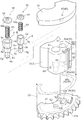
- Embodiments according to the present invention will be described with reference to FIGS. First, based on FIG.1 and FIG.2, the whole structure of the valve timing control apparatus 1 is demonstrated.
- the valve opening / closing timing control device 1 is arranged coaxially with the external rotor 2 as a drive side rotating member that rotates synchronously with a crankshaft of an engine (not shown), and synchronously rotates with the camshaft 9. And an internal rotor 3 as a driven side rotating member.
- the external rotor 2 includes a rear plate 21 attached to the side to which the camshaft 9 is connected, a front plate 22 attached to the side opposite to the side to which the camshaft 9 is connected, and the rear plate 21 and the front plate 22. It is comprised from the housing 23 pinched
- the internal rotor 3 housed in the external rotor 2 is integrally assembled with the tip portion of the camshaft 9 and can rotate relative to the external rotor 2 within a certain range.
- the housing 23 of the outer rotor 2 is formed with a plurality of projecting portions 24 projecting in the radially inward direction and spaced apart from each other along the S direction.
- the fluid pressure chamber 4 is formed by the protrusion 24 and the internal rotor 3. In the present embodiment, the fluid pressure chambers 4 are provided at three locations, but the present invention is not limited to this.
- Each fluid pressure chamber 4 is divided into an advance chamber 41 and a retard chamber 42 by a partition portion 31 forming a part of the inner rotor 3 or a vane 32 attached to the inner rotor 3.
- the regulation member 5 and the lock member 6 are accommodated in the regulation member accommodation part 51 and the lock member accommodation part 61 formed in the partition part 31, respectively, and constitute a regulation mechanism 50 and a lock mechanism 60. These configurations will be described later.
- the advance passage 43 formed in the inner rotor 3 communicates with the advance chamber 41.
- the retard passage 44 formed in the inner rotor 3 communicates with the retard chamber 42.
- the advance passage 43 and the retard passage 44 supply or discharge fluid to or from the advance chamber 41 and the retard chamber 42 via the fluid supply / discharge mechanism 7 to apply fluid pressure to the partition portion 31 or the vane 32. .
- the relative rotational phase of the inner rotor 3 with respect to the outer rotor 2 is displaced in the advance angle direction S1 or the retard angle direction S2 in FIG. 2, or is held at an arbitrary phase.
- As a fluid engine oil is generally used.
- the fixed range in which the outer rotor 2 and the inner rotor 3 can move relative to each other corresponds to the range in which the partition portion 31 or the vane 32 can be displaced inside the fluid pressure chamber 4.
- the volume of the advance chamber 41 is maximized in the most advanced angle phase, and the volume of the retard chamber 42 is maximized in the most retarded angle phase. That is, the relative rotational phase can be displaced between the most advanced phase and the most retarded phase.
- a torsion spring 8 is provided across the inner rotor 3 and the front plate 22.
- the internal rotor 3 and the external rotor 2 are urged by a torsion spring 8 so that the relative rotational phase is displaced in the advance angle direction S1.
- the fluid supply / discharge mechanism 7 is driven by an engine to supply a fluid 71, a passage switching valve 72 for controlling fluid supply and discharge to the advance passage 43 and the retard passage 44, and a reservoir for storing fluid. Part 74.
- the passage switching valve 72 operates based on control by the ECU 73 (engine control unit).
- the passage switching valve 72 permits the supply of fluid to the advance passage 43 and permits the discharge of fluid from the retard passage 44 to perform advance control, and the advance passage 43 and the delay passage.
- the second position 72b for performing phase holding control by prohibiting the supply and discharge of fluid to the angular passage 44 and the discharge of fluid from the advance passage 43 are permitted, and the supply of fluid to the retard passage 44 is permitted.
- a third position 72c for performing retardation control is configured to perform advance angle control at the first position 72a in a state where there is no control signal from the ECU 73.
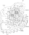
- restriction range R The configuration of the restriction mechanism 50 that restricts the relative rotation phase to the range from the most retarded phase to the intermediate lock phase (hereinafter referred to as “restriction range R”) will be described with reference to FIGS. 3 and 4.
- the intermediate lock phase refers to a relative rotation phase when locked by a lock mechanism 60 described later.
- the regulation mechanism 50 is mainly composed of a stepped cylindrical regulation member 5, a regulation member accommodating portion 51 that accommodates the regulation member 5, and a long hole formed in the surface of the rear plate 21 so that the regulation member 5 can enter. It is composed of a regulating recess 52 having a shape.
- the regulating member 5 has a shape in which cylinders having different diameters are stacked in four stages.
- the four-stage cylinders are referred to as a first step portion 5a, a second step portion 5b, a third step portion 5c, and a fourth step portion 5d in this order from the rear plate 21 side.
- the second step portion 5b is configured to have a smaller diameter than the first step portion 5a.
- the second step portion 5b, the third step portion 5c, and the fourth step portion 5d are arranged in this order. Is configured to be large.
- the third step portion 5c is provided to reduce the volume of the first fluid chamber 55 and improve the operability of the regulating member 5 when the fluid is supplied to the first fluid chamber 55.
- the first step portion 5a is formed so as to be able to enter the restricting recess 52, and when the first step portion 5a enters the restricting recess 52, the relative rotational phase is restricted within the restriction range R.
- a cylindrical recess 5f is formed in the fourth step portion 5d and the spring 53 is accommodated.
- a through hole 5g is formed in the central portion of the regulating member 5 in order to relax the resistance of the fluid when the regulating member 5 moves in the urging direction and improve the operability.
- a plug member 54 is provided between the regulating member 5 and the front plate 22, and a spring 53 is attached between the plug member 54 and the bottom surface of the recess 5f.
- the notch 54a formed in the plug member 54 allows the fluid to be discharged to the outside of the valve opening / closing timing control device 1 through a discharge channel (not shown) when the regulating member 5 moves to the front plate 22 side. 5 contributes to the improvement of operability.
- the restricting member accommodating portion 51 is formed in the internal rotor 3 along the direction of the rotation axis of the camshaft 9 (hereinafter referred to as “rotation axis”), and extends from the front plate 22 side to the rear plate 21 side. Through the inner rotor 3.
- the restricting member accommodating portion 51 has, for example, a shape in which cylindrical spaces with different diameters are stacked in two stages, and the restricting member 5 is formed so as to be movable therein.
- the regulating recess 52 has an arc shape centered on the rotational axis, and is formed so that its position in the radial direction is slightly different from a lock recess 62 described later.
- the restriction recess 52 is in contact with the second end 52b so that the relative rotation phase becomes the intermediate lock phase when the restriction member 5 is in contact with the first end 52a.
- the relative rotational phase is the most retarded phase. That is, the restriction recess 52 corresponds to the restriction range R.
- the restricting member 5 is accommodated in the restricting member accommodating portion 51 and is always biased toward the rear plate 21 by the spring 53.
- the first step portion 5 a of the restricting member 5 enters the restricting recess 52, the relative rotational phase is restricted within the restricting range R, and a “restricted state” is created.
- the restricting state is released and a “regulation releasing state” is established.
- the first fluid chamber 55 is formed by the restricting member 5 and the restricting member accommodating portion 51.
- the fluid is supplied to the first fluid chamber 55 and the fluid pressure acts on the first pressure receiving surface 5e, the regulating member 5 moves toward the front plate 22 against the urging force of the spring 53, and the regulation is released. .
- the configuration of the flow path for supplying and discharging fluid to the first fluid chamber 55 will be described later.
- the lock mechanism 60 includes a stepped cylindrical lock member 6, a lock member accommodating portion 61 that accommodates the lock member 6, and a circular hole formed on the surface of the rear plate 21 so that the lock member 6 can be inserted. And a lock recess 62 having a shape.
- the lock member 6 has a shape in which, for example, three stages of cylinders having different diameters are stacked.
- the three-stage cylinders are referred to as a first step portion 6a, a second step portion 6b, and a third step portion 6c in order from the rear plate 21 side.
- the first step portion 6a, the second step portion 6b, and the third step portion 6c are configured so as to increase in diameter in order.
- the first step portion 6a is formed so as to be able to enter the lock recess 62, and when the first step portion 6a enters the lock recess 62, the relative rotational phase is locked to the intermediate lock phase.
- a cylindrical recess 6f is formed from the third step portion 6c to a part of the second step portion 6b, and the spring 63 is accommodated.
- a through hole 6g is formed at the center of the lock member 6 in order to reduce fluid resistance when the lock member 6 moves in the biasing direction and improve operability.
- a plug member 64 is provided between the lock member 6 and the front plate 22, and a spring 63 is attached between the plug member 64 and the bottom surface of the recess 6f.
- the notch 64a formed in the stopper member 64 enables the fluid to be discharged to the outside of the valve opening / closing timing control device 1 by a discharge passage (not shown) when the lock member 6 moves to the front plate 22 side. 6 contributes to improvement in operability.
- the lock member accommodating portion 61 is formed in the internal rotor 3 along the direction of the rotation axis, and penetrates the internal rotor 3 from the front plate 22 side to the rear plate 21 side.
- the lock member accommodating portion 61 has a shape in which cylindrical spaces having different diameters are stacked in three stages, and is formed so that the lock member 6 can be moved therein.
- the lock member 6 is housed in the lock member housing portion 61 and is always urged toward the rear plate 21 by the spring 63.
- the first step portion 6a of the lock member 6 enters the lock recess 62, the relative rotation phase is locked to the intermediate lock phase, and a “lock state” is created.
- the lock state is released and the “lock release state” is set.
- the second fluid chamber 65 and the third fluid chamber 66 are formed by the lock member 6 and the lock member accommodating portion 61.
- the fluid is supplied to the second fluid chamber 65 and the fluid pressure acts on the second pressure receiving surface 6d, the lock member 6 moves toward the front plate 22 against the biasing force of the spring 63, and the lock is released.
- the fluid is supplied to the third fluid chamber 66 and the fluid pressure acts on the third pressure receiving surface 6e, the unlocked state of the lock member 6 is maintained.
- the configuration of the flow path for supplying and discharging fluid to and from the second fluid chamber 65 and the third fluid chamber 66 will be described later.
- the restriction release channel for realizing the restriction release state includes a restriction communication path 82 and a release communication path 83.
- the restriction time communication passage 82 includes a rear plate passage 84, a first through passage 85a, and a supply passage 85c, which will be described later, and is a passage that supplies fluid to the first fluid chamber 55 in order to release the restriction state.
- the release communication path 83 is a flow path for supplying fluid to the first fluid chamber 55 in order to maintain the restriction release state when the restriction member 5 is retracted from the restriction recess 52.
- the rear plate passage 84 is a groove-like passage formed on the surface of the rear plate 21 on the inner rotor 3 side, and communicates with the advance chamber 41.
- the rear plate passage 84 forms a part of the rotor passage 85 only when the restricting member 5 is within a predetermined advance angle range within the restricting range R (hereinafter referred to as “restriction possible range T”). It is configured to be able to communicate with the first through passage 85a. Note that the presence of the restriction member 5 within the restriction releaseable range T means that the first step portion 5a is completely located in the region of the restriction releaseable range T.
- the rotor passage 85 is a passage formed in the internal rotor 3, and includes a first through passage 85a, a second through passage 85b, a supply passage 85c, and a discharge passage 85d.
- the first through passage 85a and the second through passage 85b are formed on the radially outer side surface of the inner rotor 3 so as to form a straight line along the direction of the rotation axis.
- the end of the first through passage 85a on the rear plate 21 side is configured to communicate with the rear plate passage 84 when the restriction member 5 is within the restriction releaseable range T.
- the end of the second through passage 85b on the front plate 22 side is connected to the discharge passage 85d.
- the supply path 85 c branches off from the boundary between the first through path 85 a and the second through path 85 b and communicates with the first fluid chamber 55.
- the discharge path 85d is formed in an L shape in a plan view on the surface of the inner rotor 3 on the front plate 22 side, and when the restricting member 5 is in a predetermined range on the advance side from the restrictable range T. Only, it is configured to communicate with a discharge hole 87 described later.
- the restriction communication passage 82 includes the rear plate passage 84, the first through passage 85a, and the supply passage 85c. Therefore, when the restriction member 5 is within the restriction releaseable range T, the rear plate passage 84 and the first through passage 85a communicate with each other, whereby the restriction communication passage 82 communicates with the first fluid chamber 55 and fluid. And the fluid pressure is applied to the first pressure receiving surface 5e to release the restricted state.
- the release communication passage 83 is a tubular passage formed in the inner rotor 3 and communicates with the advance chamber 41.
- the release-time communication passage 83 communicates with the first fluid chamber 55 to supply fluid from the advance chamber 41 when the restriction member 5 is retracted from the restriction recess 52 and is in a restriction release state. A fluid pressure is applied to the surface 5e to maintain the restriction release state.
- the supply passage 85c is connected to the first step portion at a timing when the release-time communication passage 83 communicates with the first fluid chamber 55.
- the communication with the first fluid chamber 55 is cut off by 5a. That is, the passage for supplying fluid to the first fluid chamber 55 is alternatively configured to be either the restriction communication passage 82 or the release communication passage 83.
- the fluid is discharged from the first fluid chamber 55 via a supply passage 85 c (a part of a drain oil passage 86 described later), and the release-time communication passage.
- the supply of fluid from 83 can be cut off.
- the fluid is supplied to the first fluid chamber 55 from both the restriction time communication path 82 and the release time communication path 83. It is configured. This is because the first fluid chamber 55 is temporarily sealed when any of the communication passages is not connected to the first fluid chamber 55 when switching between the restriction communication passage 82 and the release communication passage 83. This is to prevent the smoothness of the regulating / releasing operation of the member 5 from being impaired.
- the drain flow path 86 is a flow path for quickly discharging the fluid in the first fluid chamber 55 that becomes the movement resistance of the restriction member 5 when the restriction member 5 enters the restriction recess 52.
- the drain passage 86 includes a supply passage 85c, a second through passage 85b, a discharge passage 85d, and a discharge hole 87.
- the discharge hole 87 is formed so as to penetrate the front plate 22 in the direction of the rotation axis.
- the drain flow path 86 is configured to communicate only when the regulating member 5 is within a predetermined range on the advance side of the restriction releaseable range T, and is not communicated when the regulating member 5 is within the restriction releaseable range T. It is. With this configuration, when the rear plate passage 84 and the first through passage 85 a communicate with each other, the fluid supplied from the advance chamber 41 is prevented from being discharged through the drain passage 86 as it is.
- the unlocking flow path 88 is a tubular passage formed in the inner rotor 3 and communicates with the retardation chamber 42.
- the unlocking flow path 88 is a flow path for supplying the fluid from the retarded angle chamber 42 to the second fluid chamber 65, applying fluid pressure to the second pressure receiving surface 6 d, and retracting the lock member 6 from the lock recess 62. It is.
- the communication flow path 89 is a tubular passage formed in the inner rotor 3, and is in a state where the regulation is released and the lock member 6 is moved to the front plate 22 side to some extent, the first fluid chamber 55 and the third fluid chamber.
- 66 is configured to communicate with 66.
- the release communication path 83, the first fluid chamber 55, the communication flow path 89, and the third fluid chamber 66 communicate with each other, the fluid supplied from the advance chamber 41 to the first fluid chamber 55 is also supplied to the third fluid chamber 66. Therefore, the restriction release state and the lock release state can be maintained.
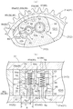
- Fig. 5 shows the state when the engine is started.
- the advance angle control is performed because the passage switching valve 72 is in the first position 72a.
- the restriction member 5 is outside the restriction release possible range T, no fluid is supplied from the restriction communication path 82 to the first fluid chamber 55.
- the release time communication passage 83 is not in communication with the first fluid chamber 55, no fluid is supplied to the first fluid chamber 55. Therefore, the locked state is maintained.
- Fig. 6 shows the state when the engine is switched to retard angle control in order to release the locked state after starting the engine.
- fluid is supplied from the retard chamber 42 to the second fluid chamber 65 via the lock release flow path 88, and the lock member 6 is withdrawn from the lock recess 62 to release the locked state.
- the regulating member 5 moves in the retarding direction within the regulating recess 52.
- the ECU 73 switches to advance angle control.
- the state at this time is shown in FIG. Since the rear plate passage 84 and the first through passage 85 a communicate with each other, the fluid is supplied from the restriction communication passage 82 to the first fluid chamber 55. Then, the restricting member 5 is withdrawn from the restricting recess 52 and the restricted state is released.
- the angle sensor detects that the restriction member 6 is in the relative rotation phase located within the restriction releaseable range T. Actually, the restricting member 6 may not reach the restriction release possible range T. In such a case, even if the advance angle control is switched, the restriction communication path 82 and the first fluid chamber 55 are not in communication with each other, so that no fluid is supplied to the first fluid chamber 55 and the restriction state is released. I can't.
- the angle sensor switches to advance angle control immediately after detecting that the restricting member 6 has reached the relative rotation phase located within the restriction releaseable range T.
- the restriction member 6 is configured to be surely positioned within the restriction release possible range T by continuing the retard control for a predetermined time from the detected time point. With this configuration, the restricted state can be reliably released.
- the sensor for detecting the relative rotation phase is not limited to the angle sensor for detecting the rotation angle of the camshaft, and other sensors can be used.
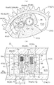
- FIG. 8 shows the state when the restriction release state and the lock release state are maintained by the advance angle control.
- Fig. 9 shows the state when the advance angle control is performed in the normal operation state.
- the advance angle chamber 41, the release communication path 83, the first fluid chamber 55, the communication flow path 89, and the third fluid chamber 66 communicate with each other, so that the restriction release state and the lock release state are maintained.
- the lead angle operates in the state where it is set.
- Fig. 10 shows the state when the retard control is performed in the normal operation state.
- the fluid is supplied from the retard chamber 42 to the second fluid chamber 65, the unlocked state is maintained.
- the regulating member 5 is urged by the spring 53 and comes into contact with the rear plate 21.
- the regulating member 5 slides on the surface of the rear plate 21, it does not hinder driving.
- the restricting recess 52 and the lock recess 62 are formed at positions shifted in the radial direction, the restricting member 5 does not enter the lock recess 62.
- FIG. 11 shows a state in which the discharge passage 85d and the discharge hole 87 communicate with each other by the advance angle control and the phase is rotated until the drain flow passage 86 functions.
- the restriction release state and the lock release state are maintained ("first state" in the present invention).
- the drain flow path 86 is in communication, when the restricting member 5 enters the restricting recess 52 in the next procedure, the fluid can be discharged from the first fluid chamber 55 and promptly set to the restricted state.
- FIG. 12 shows a state in which the restriction state is realized by switching to the retard angle control (“second state” in the present invention). If the retard angle control is maintained even after the restricting member 5 enters the restricting recess 52, the restricting state is released when the restricting member 5 is positioned within the restriction release possible range T and is next switched to the advance angle control. End up. For this reason, after entering the restricted state, it is necessary to switch to the advance angle control before the restricting member 5 is positioned within the restriction releaseable range T and the rear plate passage 84 and the first through passage 85a communicate with each other. .
- the first state, the second state, and the third state can be freely switched by the advance / retard angle control. For this reason, even if the operation of the regulating member 5 and the lock member 6 is not performed as expected and the locked state is not achieved, the advance / retard angle control can be repeated to realize the locked state again. Therefore, the locked state can be achieved during engine operation.
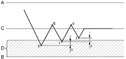
- the restriction release enabling phase D is a phase corresponding to the restriction release enabling range T.
- the angle sensor detects that the restriction release enabling phase D has not been reached, if the actual relative rotation phase has reached the restriction release enabling phase D, switching to advance control (point p) will exceed the lock phase C. Move relative to the advance side. Then, the ECU 73 determines that the locked state has not been realized, and switches to the retard control (q point). Switching to the next advance angle control (point r) is on the lock phase C side by a predetermined interval x from the point p. However, since the r point also belongs to the restriction cancelable phase D, the locked state cannot be realized and the control is switched again to the retard control (s point).
- control is switched to advance angle control at a phase on the lock phase C side by a predetermined interval x from the point r (point t). Since the point t is not included in the restriction releaseable phase D, the restricted state can be realized, and then the locked state can be realized.
- the locked state can be reliably realized by executing the retry control while shifting the phase to be switched to the advance angle control to the lock phase C side by a predetermined interval x.
- the switching phase to advance angle control may be determined based on the detection angle of the angle sensor.
- the predetermined interval x does not always have to be constant, and may be set so as to gradually increase or decrease.
- the restriction mechanism 50 is disposed on the retard side relative to the lock mechanism 60, but may be disposed on the advance side. At this time, by replacing “advance angle” and “retard angle”, the locked state can be realized before the engine is stopped, as in this embodiment.
- the present invention realizes a locked state before the engine is stopped by controlling the restriction mechanism and the lock mechanism during engine operation, and eliminates the need for a dedicated switching valve for controlling the restriction mechanism and the lock mechanism. It can be used for an opening / closing timing control device.
- Valve opening / closing timing control device External rotor (drive side rotating member) 3 Internal rotor (driven side rotating member) 4 Fluid Pressure Chamber 5 Restriction Member 6 Lock Member 31 Partition Part 41 Advance Angle Chamber 42 Delay Angle Chamber 51 Restriction Member Housing 52 Restriction Recess 53 Spring (Biasing Member) 55 1st fluid chamber 61 Lock member accommodating part 62 Lock recessed part 63 Spring (biasing member) 65 Second fluid chamber 66 Third fluid chamber 82 Restriction communication passage (regulation release passage) 83 Release passage (regulation release flow path) 86 Drain flow path 88 Unlock flow path 89 Communication flow path
Landscapes
- Engineering & Computer Science (AREA)
- Mechanical Engineering (AREA)
- General Engineering & Computer Science (AREA)
- Valve Device For Special Equipments (AREA)
Abstract
Description
弁開閉時期制御装置1は、不図示のエンジンのクランクシャフトに対して同期回転する駆動側回転部材としての外部ロータ2と、外部ロータ2に対して同軸上に配置され、カムシャフト9と同期回転する従動側回転部材としての内部ロータ3とを備えている。
相対回転位相を最遅角位相から中間ロック位相までの範囲(以下、「規制範囲R」と称する)に規制する規制機構50の構成について、図3及び図4に基づき説明する。中間ロック位相とは、後述のロック機構60によってロックされるときの相対回転位相を指す。
相対回転位相を中間ロック位相にロックするロック機構60の構成について、図3及び図4に基づき説明する。ロック機構60は、主に段付き円筒形のロック部材6と、ロック部材6を収容するロック部材収容部61と、ロック部材6が突入可能となるようリアプレート21の表面に形成された円孔形状のロック凹部62とから構成される。
規制解除状態を実現するための規制解除流路は、規制時連通路82と解除時連通路83とを備えている。規制時連通路82は、後述するリアプレート通路84、第1貫通路85a及び供給路85cからなり、規制状態を解除するために第1流体室55に流体を供給する流路である。また、解除時連通路83は、規制部材5が規制凹部52から退出しているときに、規制解除状態を保持するために第1流体室55に流体を供給する流路である。
ドレン流路86は、規制部材5が規制凹部52に突入するときに、規制部材5の移動抵抗となる第1流体室55内の流体を速やかに排出するための流路である。ドレン流路86は、供給路85c、第2貫通路85b、排出路85d及び排出孔87からなる。排出孔87は、フロントプレート22を回転軸芯の方向に貫通するよう形成されている。
ロック解除流路88は、内部ロータ3内に形成された管状の通路であり、遅角室42と連通している。ロック解除流路88は、第2流体室65に遅角室42から流体を供給して、第2受圧面6dに流体圧を作用させ、ロック部材6をロック凹部62から退出させるための流路である。
連通流路89は、内部ロータ3内に形成された管状の通路であり、規制解除状態かつロック部材6がフロントプレート22の側にある程度移動した状態で、第1流体室55と第3流体室66とを連通するように構成されている。解除時連通路83、第1流体室55、連通流路89及び第3流体室66が連通すると、進角室41から第1流体室55に供給された流体が第3流体室66にも供給されるため、規制解除状態とロック解除状態を保持することができる。
以上説明した規制機構50、ロック機構60及び各流路を用いて、ロック状態を解除する手順について、図5~図8に基づき説明する。
次に、上述の手順により規制解除状態及びロック解除状態が実現され、通常の運転状態となったときの動作について、図9及び図10に基づき説明する。
最後に、まず規制状態とした後、ロック状態とする手順について、図11~図13に基づき説明する。
2 外部ロータ(駆動側回転部材)
3 内部ロータ(従動側回転部材)
4 流体圧室
5 規制部材
6 ロック部材
31 仕切部
41 進角室
42 遅角室
51 規制部材収容部
52 規制凹部
53 スプリング(付勢部材)
55 第1流体室
61 ロック部材収容部
62 ロック凹部
63 スプリング(付勢部材)
65 第2流体室
66 第3流体室
82 規制時連通路(規制解除流路)
83 解除時連通路(規制解除流路)
86 ドレン流路
88 ロック解除流路
89 連通流路
Claims (12)
- 内燃機関のクランクシャフトに対して同期回転する駆動側回転部材と、
前記駆動側回転部材に対して同軸上に配置され、前記内燃機関の弁開閉用のカムシャフトに同期回転する従動側回転部材と、
前記駆動側回転部材と前記従動側回転部材とで形成された流体圧室と、
前記流体圧室を進角室と遅角室とに仕切るよう前記駆動側回転部材及び前記従動側回転部材の少なくとも一方に設けられた仕切部と、
前記駆動側回転部材又は前記従動側回転部材の何れか一方の回転部材に配置されると共に、何れか他方の回転部材に対して出退可能な規制部材と、
前記他方の回転部材に形成され、前記規制部材が突入して、前記駆動側回転部材に対する前記従動側回転部材の相対回転位相を最進角位相又は最遅角位相の何れか一方から前記最進角位相と前記最遅角位相との間の所定位相までの範囲に規制する規制凹部と、
前記規制部材を設けた前記一方の回転部材に配置されると共に、前記他方の回転部材に対して出退可能なロック部材と、
前記他方の回転部材に形成され、前記ロック部材が突入して、前記駆動側回転部材に対する前記従動側回転部材の相対回転位相を前記所定位相にロックするロック凹部と、
前記規制部材による規制を解除する流体を前記ロック部材に供給可能で、前記ロック部材によるロックを解除する流体を前記規制部材に供給不可能な連通流路とを備え、
前記規制部材は前記連通流路を連通又は非連通に切り換える弁開閉時期制御装置。 - 前記連通流路を連通させた状態で、前記規制部材による規制を解除し、前記ロック部材によるロックを解除する第1状態と、前記ロック部材によるロックを解除し、前記規制部材により規制する第2状態と、前記連通流路を非連通とした状態で、前記規制部材を規制し、前記ロック部材をロックする第3状態とに切換可能に構成してある請求項1に記載の弁開閉時期制御装置。
- 前記進角室及び前記遅角室のうち何れか一方に流体を供給して前記第3状態から前記第2状態に移行し、前記進角室及び前記遅角室のうち何れか他方に流体を供給して前記第2状態から前記第1状態に移行するよう構成されている請求項2に記載の弁開閉時期制御装置。
- 前記第1状態と、前記第2状態と、前記第3状態とに切換可能な流体制御手段は、
前記規制部材の規制を解除する流体が注入される第1流体室を備えつつ、前記一方の回転部材に形成された、前記規制部材を収容する規制部材収容部と、
前記ロック部材のロックを解除する流体が注入される第2流体室と、当該第2流体室とは別に設けられ、ロック解除された前記ロック部材をロック解除状態に保持する流体が注入される第3流体室とを備えつつ、前記一方の回転部材に形成された、前記ロック部材を収容するロック部材収容部と、
前記進角室及び前記遅角室のうち何れか一方と、前記第1流体室とを連通する規制解除流路と、
前記進角室及び前記遅角室のうち何れか他方と、前記第2流体室とを連通するロック解除流路と、
前記第1流体室と前記第3流体室とを連通するよう構成された前記連通流路とを備え、
前記規制解除流路を介して、前記第1流体室・前記連通流路・前記第3流体室に流体を供給して前記第1状態と、
前記ロック解除流路を介して、前記第2流体室に流体を供給して前記第2状態と、
前記第1流体室・前記第2流体室・前記第3流体室の何れにも流体を供給せず前記第3状態とに切換可能に構成されている請求項2又は3に記載の弁開閉時期制御装置。 - 前記規制解除流路は、
前記規制部材が前記規制凹部に突入している状態で、前記進角室及び前記遅角室のうち何れか一方と前記第1流体室とを連通可能な規制時連通路と、
前記規制部材が前記規制凹部から退出している状態で、前記進角室及び前記遅角室のうち何れか一方と前記第1流体室とを連通する解除時連通路と、
を備えている請求項4に記載の弁開閉時期制御装置。 - 前記規制時連通路は、
前記規制部材が、前記最進角位相又は前記最遅角位相の何れか一方から前記所定位相までの範囲内で移動する際に、
前記駆動側回転部材と前記従動側回転部材とが前記所定位相にある状態から、最進角位相又は最遅角位相の何れか一方の位相に向かって予め設定した位相以内にあるとき、
前記進角室及び前記遅角室のうち何れか一方と前記第1流体室とが非連通となるように構成してある請求項5に記載の弁開閉時期制御装置。 - 前記カムシャフトの回転角度を検出する角度センサが、前記進角室及び前記遅角室のうち何れか一方と前記第1流体室とが前記規制解除流路により連通する相対回転位相であることを検出し、当該検出時の相対回転移動を所定時間継続した後、相対回転移動の方向を切り換えて、前記第2状態から前記第1状態に移行するよう構成されている請求項4から6の何れか一項に記載の弁開閉時期制御装置。
- 前記規制部材が前記規制凹部に突入可能な相対回転位相のときに、前記第2状態に移行すべく相対回転移動の方向を切り換え、その後に前記規制部材が前記規制凹部に突入可能な相対回転位相外に相対回転移動した際には、相対回転移動の方向を戻し、前記規制部材が前記規制凹部に突入可能な相対回転位相となってから、再度相対回転移動の方向を切り換えるリトライ制御を実行する請求項2から7の何れか一項に記載の弁開閉時期制御装置。
- 前記リトライ制御の際に相対回転移動の方向を切り換える相対回転位相を、その直前に相対回転移動の方向を切り換えたときの相対回転位相よりも前記所定位相側に所定間隔異なる位相となるように構成されている請求項8に記載の弁開閉時期制御装置。
- 前記規制部材が、前記最進角位相又は前記最遅角位相の何れか一方から前記所定位相までの範囲内で移動する際、もしくは前記ロック部材がロック状態の際に、
前記進角室及び前記遅角室のうち何れか一方と前記第1流体室とが連通していないとき、前記第1流体室に連通して大気開放するドレン流路を形成してある請求項1から9の何れか一項に記載の弁開閉時期制御装置。 - 前記流体供給制御手段は、内燃機関の回転速度が予め設定した値以下となった状態で、前記規制部材及び前記ロック部材を、順次、前記第1状態・前記第2状態・前記第3状態に移行させるよう構成してある請求項1から10の何れか一項に記載の弁開閉時期制御装置。
- 前記規制部材及び前記ロック部材には、前記規制部材及び前記ロック部材を前記規制凹部の側及び前記ロック凹部の側に各別に付勢する付勢部材をそれぞれ備えている請求項1から11の何れか一項に記載の弁開閉時期制御装置。
Priority Applications (4)
| Application Number | Priority Date | Filing Date | Title |
|---|---|---|---|
| CN201080012782.0A CN102356215B (zh) | 2009-07-01 | 2010-02-12 | 阀开闭定时控制装置 |
| EP10793873.0A EP2397661B1 (en) | 2009-07-01 | 2010-02-12 | Valve timing control device |
| US13/256,883 US8360022B2 (en) | 2009-07-01 | 2010-02-12 | Valve timing control apparatus |
| JP2011520800A JP4930814B2 (ja) | 2009-07-01 | 2010-02-12 | 弁開閉時期制御装置 |
Applications Claiming Priority (2)
| Application Number | Priority Date | Filing Date | Title |
|---|---|---|---|
| JP2009-157262 | 2009-07-01 | ||
| JP2009157262 | 2009-07-01 |
Publications (1)
| Publication Number | Publication Date |
|---|---|
| WO2011001702A1 true WO2011001702A1 (ja) | 2011-01-06 |
Family
ID=43410787
Family Applications (1)
| Application Number | Title | Priority Date | Filing Date |
|---|---|---|---|
| PCT/JP2010/052075 Ceased WO2011001702A1 (ja) | 2009-07-01 | 2010-02-12 | 弁開閉時期制御装置 |
Country Status (5)
| Country | Link |
|---|---|
| US (1) | US8360022B2 (ja) |
| EP (1) | EP2397661B1 (ja) |
| JP (1) | JP4930814B2 (ja) |
| CN (1) | CN102356215B (ja) |
| WO (1) | WO2011001702A1 (ja) |
Cited By (11)
| Publication number | Priority date | Publication date | Assignee | Title |
|---|---|---|---|---|
| JP2013002373A (ja) * | 2011-06-17 | 2013-01-07 | Hitachi Automotive Systems Ltd | 内燃機関のバルブタイミング制御装置 |
| JP2013087643A (ja) * | 2011-10-14 | 2013-05-13 | Hitachi Automotive Systems Ltd | 内燃機関のバルブタイミング制御装置 |
| JP2013092107A (ja) * | 2011-10-26 | 2013-05-16 | Hitachi Automotive Systems Ltd | 内燃機関のバルブタイミング制御装置 |
| CN103649476A (zh) * | 2011-07-07 | 2014-03-19 | 爱信精机株式会社 | 阀开闭时期控制装置及阀开闭时期控制机构 |
| US20140083384A1 (en) * | 2012-09-21 | 2014-03-27 | Hilite Germany Gmbh | Centering slot for internal combustion engine |
| US20140216377A1 (en) | 2011-07-12 | 2014-08-07 | Aisin Seiki Kabushiki Kaisha | Valve timing adjustment system |
| US9133736B2 (en) | 2011-07-12 | 2015-09-15 | Aisin Seiki Kabushiki Kaisha | Valve timing adjusting system |
| US9366161B2 (en) | 2013-02-14 | 2016-06-14 | Hilite Germany Gmbh | Hydraulic valve for an internal combustion engine |
| WO2016185918A1 (ja) * | 2015-05-20 | 2016-11-24 | 日立オートモティブシステムズ株式会社 | 内燃機関のバルブタイミング制御装置 |
| DE102012209027B4 (de) * | 2012-05-30 | 2017-06-22 | Schaeffler Technologies AG & Co. KG | Nockenwellenversteller |
| US9784143B2 (en) | 2014-07-10 | 2017-10-10 | Hilite Germany Gmbh | Mid lock directional supply and cam torsional recirculation |
Families Citing this family (19)
| Publication number | Priority date | Publication date | Assignee | Title |
|---|---|---|---|---|
| JP4816742B2 (ja) * | 2009-02-12 | 2011-11-16 | 株式会社デンソー | バルブタイミング調整装置 |
| CN102165146B (zh) * | 2009-03-25 | 2014-06-25 | 爱信精机株式会社 | 阀开闭定时控制装置 |
| CN203321606U (zh) | 2010-07-15 | 2013-12-04 | 爱信精机株式会社 | 阀开闭定时控制装置及阀开闭定时控制机构 |
| US8813700B2 (en) * | 2011-11-02 | 2014-08-26 | Schaeffler Technologies Gmbh & Co. Kg | Camshaft adjustment mechanism having a locking apparatus |
| DE102013209554A1 (de) * | 2013-05-23 | 2014-11-27 | Schaeffler Technologies Gmbh & Co. Kg | Flügelzellenversteller für eine Nockenwellenverstelleinrichtung |
| DE102014205569B4 (de) * | 2014-03-26 | 2017-01-26 | Schaeffler Technologies AG & Co. KG | Nockenwellenverstelleinrichtung |
| DE102014205568B4 (de) | 2014-03-26 | 2017-05-04 | Schaeffler Technologies AG & Co. KG | Nockenwellenverstelleinrichtung |
| DE102014206620A1 (de) | 2014-04-07 | 2015-10-08 | Schaeffler Technologies AG & Co. KG | Nockenwellenversteller mit Abflussventil |
| DE102014209641B4 (de) * | 2014-05-21 | 2018-09-20 | Schaeffler Technologies AG & Co. KG | Nockenwelleversteller mit Sperrstift zur Druckentlastung des Hydraulikkanals mit Überdeckung mittels Kulisse |
| JP6210042B2 (ja) * | 2014-09-26 | 2017-10-11 | アイシン精機株式会社 | 弁開閉時期制御装置 |
| JP6344318B2 (ja) * | 2015-06-17 | 2018-06-20 | 株式会社デンソー | バルブタイミング調整装置 |
| KR101679020B1 (ko) | 2015-12-23 | 2016-12-29 | 현대자동차주식회사 | 내연기관의 밸브타이밍 조정장치의 잠금구조 |
| KR101679016B1 (ko) | 2015-12-23 | 2017-01-02 | 현대자동차주식회사 | 내연기관의 밸브타이밍 조정장치 |
| KR101767463B1 (ko) * | 2016-01-06 | 2017-08-14 | 현대자동차(주) | 내연기관의 밸브타이밍 조정장치의 오일 드레인 구조 |
| KR101689654B1 (ko) | 2016-02-05 | 2016-12-26 | 현대자동차주식회사 | 내연기관의 밸브타이밍 조정장치용 제어밸브 |
| WO2018039308A1 (en) | 2016-08-24 | 2018-03-01 | Borgwarner Inc. | Mechanism for locking a variable cam timing device |
| US11946395B2 (en) * | 2022-02-11 | 2024-04-02 | Borgwarner Inc. | Variable cam timing phaser |
| US11994043B2 (en) * | 2022-03-03 | 2024-05-28 | Schaeffler Technologies AG & Co. KG | Contaminant pathway for camshaft phaser |
| US12338753B2 (en) * | 2023-11-13 | 2025-06-24 | Borgwarner Inc. | Variable cam timing phaser |
Citations (2)
| Publication number | Priority date | Publication date | Assignee | Title |
|---|---|---|---|---|
| JPH11311107A (ja) * | 1998-04-27 | 1999-11-09 | Aisin Seiki Co Ltd | 弁開閉時期制御装置 |
| JP2002357105A (ja) * | 2001-03-30 | 2002-12-13 | Denso Corp | バルブタイミング調整装置 |
Family Cites Families (10)
| Publication number | Priority date | Publication date | Assignee | Title |
|---|---|---|---|---|
| JP3033582B2 (ja) * | 1995-06-14 | 2000-04-17 | 株式会社デンソー | 内燃機関用バルブタイミング調整装置。 |
| GB2302391B (en) | 1995-06-14 | 1999-08-18 | Nippon Denso Co | Control apparatus for varying the rotational or angular phase between two rotational shafts |
| JP3845986B2 (ja) | 1997-10-30 | 2006-11-15 | アイシン精機株式会社 | 弁開閉時期制御装置 |
| US5836277A (en) | 1996-12-24 | 1998-11-17 | Aisin Seiki Kabushiki Kaisha | Valve timing control device |
| JP3733730B2 (ja) * | 1998-01-30 | 2006-01-11 | トヨタ自動車株式会社 | 内燃機関のバルブタイミング制御装置 |
| DE10213831A1 (de) * | 2001-03-28 | 2002-11-07 | Denso Corp | Variables Ventilsteuerzeitengerät |
| JP3736489B2 (ja) * | 2002-03-27 | 2006-01-18 | 株式会社デンソー | バルブタイミング調整装置の制御方法 |
| JP4043823B2 (ja) * | 2002-03-28 | 2008-02-06 | 三菱電機株式会社 | バルブタイミング調整装置 |
| JP5382427B2 (ja) | 2008-09-04 | 2014-01-08 | アイシン精機株式会社 | 弁開閉時期制御装置 |
| CN102165146B (zh) | 2009-03-25 | 2014-06-25 | 爱信精机株式会社 | 阀开闭定时控制装置 |
-
2010
- 2010-02-12 EP EP10793873.0A patent/EP2397661B1/en not_active Not-in-force
- 2010-02-12 CN CN201080012782.0A patent/CN102356215B/zh not_active Expired - Fee Related
- 2010-02-12 US US13/256,883 patent/US8360022B2/en not_active Expired - Fee Related
- 2010-02-12 JP JP2011520800A patent/JP4930814B2/ja not_active Expired - Fee Related
- 2010-02-12 WO PCT/JP2010/052075 patent/WO2011001702A1/ja not_active Ceased
Patent Citations (3)
| Publication number | Priority date | Publication date | Assignee | Title |
|---|---|---|---|---|
| JPH11311107A (ja) * | 1998-04-27 | 1999-11-09 | Aisin Seiki Co Ltd | 弁開閉時期制御装置 |
| JP3918971B2 (ja) | 1998-04-27 | 2007-05-23 | アイシン精機株式会社 | 弁開閉時期制御装置 |
| JP2002357105A (ja) * | 2001-03-30 | 2002-12-13 | Denso Corp | バルブタイミング調整装置 |
Non-Patent Citations (1)
| Title |
|---|
| See also references of EP2397661A4 * |
Cited By (20)
| Publication number | Priority date | Publication date | Assignee | Title |
|---|---|---|---|---|
| JP2013002373A (ja) * | 2011-06-17 | 2013-01-07 | Hitachi Automotive Systems Ltd | 内燃機関のバルブタイミング制御装置 |
| US9080475B2 (en) | 2011-07-07 | 2015-07-14 | Aisin Seiki Kabushiki Kaisha | Valve timing control device and valve timing control mechanism |
| EP2730756A4 (en) * | 2011-07-07 | 2015-01-21 | Aisin Seiki | DEVICE FOR CONTROLLING A VALVE OPENING / CLOSING TIME AND MECHANISM FOR CONTROLLING A VALVE OPENING / CLOSING TIME |
| CN103649476A (zh) * | 2011-07-07 | 2014-03-19 | 爱信精机株式会社 | 阀开闭时期控制装置及阀开闭时期控制机构 |
| CN103649476B (zh) * | 2011-07-07 | 2016-03-23 | 爱信精机株式会社 | 阀开闭时期控制装置及阀开闭时期控制机构 |
| US20140130755A1 (en) * | 2011-07-07 | 2014-05-15 | Aisin Seik Kabushiki Kaisha | Valve timing control device and valve timing control mechanism |
| US9133736B2 (en) | 2011-07-12 | 2015-09-15 | Aisin Seiki Kabushiki Kaisha | Valve timing adjusting system |
| US20140216377A1 (en) | 2011-07-12 | 2014-08-07 | Aisin Seiki Kabushiki Kaisha | Valve timing adjustment system |
| US9057292B2 (en) | 2011-07-12 | 2015-06-16 | Aisin Seiki Kabushiki Kaisha | Valve timing adjustment system |
| JP2013087643A (ja) * | 2011-10-14 | 2013-05-13 | Hitachi Automotive Systems Ltd | 内燃機関のバルブタイミング制御装置 |
| JP2013092107A (ja) * | 2011-10-26 | 2013-05-16 | Hitachi Automotive Systems Ltd | 内燃機関のバルブタイミング制御装置 |
| DE102012209027B4 (de) * | 2012-05-30 | 2017-06-22 | Schaeffler Technologies AG & Co. KG | Nockenwellenversteller |
| US20140083384A1 (en) * | 2012-09-21 | 2014-03-27 | Hilite Germany Gmbh | Centering slot for internal combustion engine |
| US9366160B2 (en) | 2012-09-21 | 2016-06-14 | Hilite Germany Gmbh | Centering slot for internal combustion engine |
| US8973542B2 (en) * | 2012-09-21 | 2015-03-10 | Hilite Germany Gmbh | Centering slot for internal combustion engine |
| US9366161B2 (en) | 2013-02-14 | 2016-06-14 | Hilite Germany Gmbh | Hydraulic valve for an internal combustion engine |
| US9784143B2 (en) | 2014-07-10 | 2017-10-10 | Hilite Germany Gmbh | Mid lock directional supply and cam torsional recirculation |
| WO2016185918A1 (ja) * | 2015-05-20 | 2016-11-24 | 日立オートモティブシステムズ株式会社 | 内燃機関のバルブタイミング制御装置 |
| JPWO2016185918A1 (ja) * | 2015-05-20 | 2017-12-21 | 日立オートモティブシステムズ株式会社 | 内燃機関のバルブタイミング制御装置 |
| US10240494B2 (en) | 2015-05-20 | 2019-03-26 | Hitachi Automotive Systems, Ltd. | Valve timing control device for internal combustion engine |
Also Published As
| Publication number | Publication date |
|---|---|
| EP2397661B1 (en) | 2013-05-01 |
| US8360022B2 (en) | 2013-01-29 |
| CN102356215A (zh) | 2012-02-15 |
| CN102356215B (zh) | 2014-07-23 |
| JPWO2011001702A1 (ja) | 2012-12-13 |
| US20120000437A1 (en) | 2012-01-05 |
| EP2397661A1 (en) | 2011-12-21 |
| JP4930814B2 (ja) | 2012-05-16 |
| EP2397661A4 (en) | 2012-01-25 |
Similar Documents
| Publication | Publication Date | Title |
|---|---|---|
| JP4930814B2 (ja) | 弁開閉時期制御装置 | |
| JP5246528B2 (ja) | 弁開閉時期制御装置及び弁開閉時期制御機構 | |
| JP5483119B2 (ja) | 弁開閉時期制御装置及び弁開閉時期制御機構 | |
| JP5360511B2 (ja) | 弁開閉時期制御装置 | |
| JP5403341B2 (ja) | 弁開閉時期制御装置 | |
| JP4605473B2 (ja) | 弁開閉時期制御装置 | |
| JP4784844B2 (ja) | 弁開閉時期制御装置 | |
| JP4609714B2 (ja) | 弁開閉時期制御装置 | |
| JP5990916B2 (ja) | 弁開閉時期制御装置 | |
| JP5120635B2 (ja) | 弁開閉時期制御装置 | |
| JP2009281190A (ja) | 弁開閉時期制御装置 | |
| EP2891773B1 (en) | Variable valve timing control apparatus | |
| JP5773195B2 (ja) | 弁開閉時期調整システム | |
| JP5974517B2 (ja) | 弁開閉時期制御装置 | |
| JPH10103030A (ja) | 弁開閉時期制御装置 | |
| JP2007154839A (ja) | 弁開閉時期制御装置 | |
| JP2019199871A (ja) | 弁開閉時期制御装置 | |
| JP2014051895A (ja) | 弁開閉時期制御装置 | |
| WO2015141475A1 (ja) | 弁開閉時期制御システム | |
| JP2005105890A (ja) | 弁開閉時期制御装置 |
Legal Events
| Date | Code | Title | Description |
|---|---|---|---|
| WWE | Wipo information: entry into national phase |
Ref document number: 201080012782.0 Country of ref document: CN |
|
| 121 | Ep: the epo has been informed by wipo that ep was designated in this application |
Ref document number: 10793873 Country of ref document: EP Kind code of ref document: A1 |
|
| WWE | Wipo information: entry into national phase |
Ref document number: 2011520800 Country of ref document: JP |
|
| WWE | Wipo information: entry into national phase |
Ref document number: 7031/DELNP/2011 Country of ref document: IN Ref document number: 2010793873 Country of ref document: EP |
|
| WWE | Wipo information: entry into national phase |
Ref document number: 13256883 Country of ref document: US |
|
| NENP | Non-entry into the national phase |
Ref country code: DE |