WO2011001771A1 - 漏洩磁束探傷方法及び装置 - Google Patents
漏洩磁束探傷方法及び装置 Download PDFInfo
- Publication number
- WO2011001771A1 WO2011001771A1 PCT/JP2010/059102 JP2010059102W WO2011001771A1 WO 2011001771 A1 WO2011001771 A1 WO 2011001771A1 JP 2010059102 W JP2010059102 W JP 2010059102W WO 2011001771 A1 WO2011001771 A1 WO 2011001771A1
- Authority
- WO
- WIPO (PCT)
- Prior art keywords
- magnetic field
- phase
- magnetic flux
- inspected
- positions
- Prior art date
- Legal status (The legal status is an assumption and is not a legal conclusion. Google has not performed a legal analysis and makes no representation as to the accuracy of the status listed.)
- Ceased
Links
Images


Classifications
-
- G—PHYSICS
- G01—MEASURING; TESTING
- G01N—INVESTIGATING OR ANALYSING MATERIALS BY DETERMINING THEIR CHEMICAL OR PHYSICAL PROPERTIES
- G01N27/00—Investigating or analysing materials by the use of electric, electrochemical, or magnetic means
- G01N27/72—Investigating or analysing materials by the use of electric, electrochemical, or magnetic means by investigating magnetic variables
- G01N27/82—Investigating or analysing materials by the use of electric, electrochemical, or magnetic means by investigating magnetic variables for investigating the presence of flaws
- G01N27/83—Investigating or analysing materials by the use of electric, electrochemical, or magnetic means by investigating magnetic variables for investigating the presence of flaws by investigating stray magnetic fields
Definitions
- the present invention relates to a method and an apparatus for flaw detection of a material to be inspected by applying an alternating magnetic field to the material to be inspected and detecting leakage magnetic flux leaking from the surface of the material to be inspected.
- a leakage magnetic flux flaw detection method using magnetism As a method for inspecting a defect of a steel material, there is a leakage magnetic flux flaw detection method using magnetism.
- a measuring object is magnetized by direct current or alternating current, and a magnetic flux leaking from the surface of the measuring object is detected mainly by a search coil as a magnetic sensor.
- a magnetoresistive element (MR), a Hall element, a magnetic impedance element (MI), and the like have begun to be used as the magnetic sensor.
- MR magnetoresistive element
- MI magnetic impedance element
- a magnetic field component or a perpendicular magnetic field component is measured by a magnetic sensor.
- a method of magnetizing the measurement object there are a method of magnetizing to DC by an exciting coil and a method of magnetizing to AC.
- the method of magnetizing to a direct current is mainly used as a method for flaw detection inside because a cross section to be measured can be magnetized uniformly.
- the AC magnetizing method has a skin effect depending on the frequency, and is therefore mainly used for flaw detection near the surface of the material.
- magnetic sensors having sensitivity down to low frequencies such as MR, Hall elements, and MI elements, can be excited at low frequencies, and therefore are applied when detecting defects in the deep part of the measurement target.
- the leakage flux testing method is generally included in the eddy current testing method.
- the eddy current flaw detection method and the leakage magnetic flux flaw detection method are flaw detection methods having the same configuration, and are methods in which a magnetic field is applied to a measurement target and measurement is performed by a magnetic sensor.
- An eddy current flaw detection method for detecting a magnetic field component parallel to the sample surface by applying a low-frequency magnetic field is described in Japanese Patent No. 3987941 (Patent Document 1).
- Patent Document 2 Japanese Patent Laid-Open No. 2007-64628 describes an analysis method for identifying the depth and size of a defect from a graph of signal intensity change.
- the magnetic field strength change and the phase change in the measured range are individually graphed or mapped to detect and display the defect.
- the variation greatly affects the measurement result. Therefore, it may be difficult to identify the exact defect position and size.
- an object of the present invention is to provide a leakage magnetic flux flaw detection method and apparatus for performing measurement and analysis in which a true signal due to a defect can be accurately captured without the measurement result being affected by fluctuations in the measurement state.
- the present invention Magnetic field applying means for applying an alternating magnetic field to the material to be inspected; A sensor for detecting leakage magnetic flux leaking from the material to be inspected; An analysis means for analyzing a change in signal and phase output from the sensor; A leakage magnetic flux flaw detection method for flaw detection by detecting leakage magnetic flux leaking from the material to be inspected, Applying the alternating magnetic field in a predetermined magnetic field application direction by the magnetic field applying means to generate a magnetic flux parallel to the surface of the material to be inspected; Detecting a magnitude of a magnetic field in a direction parallel to the predetermined magnetic field application direction at a plurality of positions on the surface of the inspection object by the sensor; Detecting the output of the sensor into two signals having the same frequency as the alternating magnetic field and phases orthogonal to each other, and inputting the signals to the analysis means; Based on the two signals input to the analysis means, the magnetic field magnitude data and the phase data at the plurality of positions are calculated, and a sine value of data obtained by adding a correction phase
- the present invention is a leakage magnetic flux flaw detection method including a step of displaying each value of the product by a display means.
- the present invention Magnetic field applying means for applying an alternating magnetic field to the material to be inspected; A sensor for detecting leakage magnetic flux leaking from the material to be inspected; An analysis means for analyzing a change in signal and phase output from the sensor; A leakage magnetic flux flaw detection apparatus for flaw detection by detecting leakage magnetic flux leaking from the material to be inspected, Lock-in detection means for detecting the output of the sensor into two signals having the same frequency as the alternating magnetic field and phases orthogonal to each other;
- the alternating magnetic field is applied in a predetermined magnetic field application direction to generate a magnetic flux parallel to the surface of the inspection object,
- the sensor detects the magnitude of a magnetic field in a direction parallel to the predetermined magnetic field application direction at a plurality of positions on the surface of the inspection object,
- the analyzing means calculates the magnetic field magnitude data and the phase data at the plurality of positions based on the two signals, and a sine value or cosine of data obtained by adding a correction phase for calibration to the phase.
- the correction phase for calibration is a common adjustment phase that adjusts the phase by adding in common to the phase at the plurality of positions.
- Each value of the product at the plurality of positions is a common adjustment phase from which only the magnetic field change due to the defect can be extracted from the values of the products at the plurality of positions obtained by arbitrarily changing the common adjustment phase. It is a leakage magnetic flux flaw detector which is each value of the product in the plurality of positions at the time.
- the present invention is a leakage magnetic flux flaw detector provided with input means for inputting the calibration correction phase.
- the present invention is a leakage magnetic flux flaw detector provided with scanning means for moving the sensor in a direction crossing the application direction of the alternating magnetic field.
- the present invention is the leakage magnetic flux flaw detector in which the magnetic field applying means has two magnetic pole portions, and a plurality of the sensors are arranged side by side between the two magnetic pole portions.
- the two magnetic pole portions are a set of excitation coils, the surfaces of the excitation coils are arranged opposite to each other, and a material to be inspected can be inserted into the excitation coil, and the central axis of the excitation coil Is a leakage magnetic flux flaw detector provided with a plurality of the sensors arranged in parallel to each other.
- the magnetic field change corresponding to the position of the defect can be detected by detecting the parallel component of the leakage magnetic flux, and the magnetic field signals due to the leakage magnetic flux obtained by the sensor are two signals orthogonal to each other.
- Dividing into signal intensity and phase the cosine or sine of the trigonometric function of the phase obtained by adding the phase at each measurement point measured at multiple positions and the correction phase for calibration at all measurement points is obtained.
- the amount multiplied by the trigonometric function an optimal signal change can be obtained, and a more accurate defect position and size can be identified.
- the present invention by displaying each value of the product on the display means, it is possible to easily obtain an optimal signal change when the correction phase is arbitrarily changed, and to obtain a more accurate defect position and size. Can be identified.
- the present invention it is possible to detect a magnetic field change corresponding to the position of the defect by detecting the parallel component of the leakage magnetic flux, and further divide the magnetic field signal obtained by the sensor by the lock-in detection means into signal intensity and phase. Calculate the cosine or sine of the trigonometric function of the phase obtained by adding the phase at each measurement point measured at multiple positions and the correction phase for calibration at all measurement points, and multiplying the signal strength by the trigonometric function Thus, it is possible to obtain an optimum signal change and to identify a more accurate defect position and size.
- the correction phase can be arbitrarily input.
- defects can be detected in two dimensions.
- the present invention by arranging a plurality of sensors, it is not necessary to move the sensor between the magnetic pole portions during inspection, and it is possible to perform inspection at a time without being affected by fluctuations in the measurement state.
- the inspection object can be passed through the excitation coil by making the surfaces of the set of excitation coils face each other, and in parallel with the central axis connecting the set of excitation coils.
- Magnetic flux can be introduced into the inspection material.
- the magnetic flux leaking to the surface due to the defect of the material to be inspected can be easily detected by the magnetic flux with good directivity, and the component in the same direction as the magnetic flux is measured as a sensor. Can be detected.
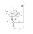
- FIG. 1 is a schematic diagram showing a basic configuration of a leakage flux testing apparatus to which a leakage flux testing method according to an embodiment of the present invention is applied.
- the leakage magnetic flux flaw detection apparatus is an apparatus for flaw detection by detecting leakage magnetic flux leaking from the inspection object 1-1.
- the leakage magnetic flux flaw detector mainly includes a magnetic field application means 15, a magnetic sensor array 6-1, a lock-in detector 10, a signal analysis device 11, and a display mechanism 12.
- the magnetic field applying means 15 is a magnetic field applying means for applying an alternating magnetic field to a material to be inspected 1-1 having a predetermined thickness, and includes a pair of excitation coils 2-1, 2-2, a yoke material 3, and an excitation coil power source. 4 and transmitter 5.
- the exciting coils 2-1 and 2-2 are examples of magnetic pole portions, and are wound around opposite ends of the U-shaped yoke material 3 in opposite directions.
- the excitation coils 2-1 and 2-2 are each connected to an excitation coil power source 4, and a transmitter 5 is connected to the excitation coil power source 4.
- the magnetic field applying means 15 excites the exciting coils 2-1 and 2-2 by energizing the exciting coils 2-1 and 2-2 with an alternating current from the exciting coil power source 4, and the exciting coils 2-1 and 2-2. -2 can be brought into contact with the surface of the inspection object 1-1 to generate a magnetic flux so as to be parallel to the surface of the inspection object 1-1. That is, the magnetic field applying means 15 applies an alternating magnetic field in a predetermined magnetic field application direction (in this embodiment, a direction parallel to a straight line connecting the exciting coils 2-1 and 2-2), and the surface of the material to be inspected. Can generate a magnetic flux parallel to the.
- the shape of the yoke material 3 is not limited to a U-shape, and may be a U-shape.
- the magnetic sensor array 6-1 is a sensor for detecting a leakage magnetic flux leaking from the inspection object 1-1, and a plurality of magnetic sensors 7-1 to 10 are arranged in the longitudinal direction of the magnetic sensor array 6-1. It is an array sensor.
- the magnetic sensor array 6-1 is mounted on the surface of the inspection object 1-1 in a state where a plurality of magnetic sensors 7-1 to 10 are arranged in a direction parallel to a straight line connecting the excitation coils 2-1 and 2-2.
- the plurality of magnetic sensors 7-1 to -10 are arranged in a plurality of positions on the surface of the inspection object 1-1, in the magnetic field application direction of the magnetic field application means 15 (straight lines connecting the excitation coils 2-1 and 2-2).
- the magnetic field component in the direction parallel to the upper direction can be detected. That is, the magnetic sensor array 6-1 measures the magnitude of the magnetic field in a direction parallel to the magnetic field application direction of the magnetic field application means 15 in the longitudinal direction of the magnetic sensor array 6-1 on the surface of the inspection object 1-1 at a plurality of points. can do.
- the plurality of magnetic sensors 7-1 to -10 are connected to the corresponding magnetic sensor measurement circuits 8-1 to 10, and the corresponding magnetic sensor 7-1 is connected to the magnetic sensor measurement circuits 8-1 to -10. ⁇ 10 are driven.
- the magnetic sensor measurement circuits 8-1 to 8-10 are connected to the multiplexer 9.
- the lock-in detector 10 is lock-in detection means for detecting the output signal of the magnetic sensor array 6-1 into two signals having the same frequency as the AC magnetic field and phases orthogonal to each other.
- the lock-in detector 10 detects only a signal that is synchronized with the AC frequency of the AC current passed through the exciting coils 2-1 and 2-2. In other words, the lock-in detector 10 detects two signals having the same frequency as the exciting coils 2-1 and 2-2 and having phases different from each other by 90 degrees.
- the lock-in detector 10 is connected to the multiplexer 9.
- the signal analysis device 11 is a means for analyzing a change in signal and phase output from the magnetic sensor array 6-1 via the lock-in detector 10, and is connected to the lock-in detector 10. That is, the signal analyzer 11 calculates the magnetic field magnitude data and the phase data at a plurality of positions based on the two signals detected by the lock-in detector 10, and corrects the calibration for the phase. Find the sine value or cosine value of the data with the phase added, find the product of the magnetic field magnitude data and the sine value or cosine value, and identify the defect using each value of the product at the plurality of positions can do. That is, the signal analysis device 11 can analyze the signal detected by the lock-in detector 10 by a predetermined analysis method. A display mechanism 12 is connected to the signal analysis device 11.
- the signal analyzer 11 is connected to input means (not shown) for inputting the calibration correction phase.
- the calibration correction phase is commonly applied to all of the plurality of magnetic sensors 7-1 to 10 included in the magnetic sensor array 6-1 when the magnetic sensor array 6-1 is calibrated.
- Phase adjustment phase (hereinafter referred to as a common adjustment phase ⁇ ).
- the display mechanism 12 is a display means for displaying an analysis result by the signal analysis device 11.
- the display mechanism 12 is, for example, a device under test such as a signal output via the lock-in detector 10 and a phase change, or a product value of the magnetic field magnitude data and the sine value or the cosine value. Information necessary for identifying defects on the surface of the material 1-1 can be displayed.
- the leakage magnetic flux flaw detection method for flaw detection by detecting a leakage magnetic flux leaking from the material to be inspected 1-1 using the leakage magnetic flux flaw detection apparatus, Applying the alternating magnetic field in a predetermined magnetic field application direction by the magnetic field applying means 15 to generate a magnetic flux parallel to the surface of the inspection object 1-1; Detecting a magnitude of a magnetic field in a direction parallel to the predetermined magnetic field application direction at a plurality of positions on the surface of the inspection object 1-1 by the magnetic sensor array 6-1; Detecting the output of the magnetic sensor array 6-1 into two signals having the same frequency as the AC magnetic field and phases orthogonal to each other, and inputting the signals to the signal analysis device 11; Based on the two signals input to the signal analysis device 11, the magnetic field magnitude data and the phase data at the plurality of positions are calculated, and a sine of data obtained by adding a common adjustment phase ⁇
- an alternating magnetic field is applied in a predetermined application direction by the exciting coils 2-1 and 2-2.
- a magnetic flux parallel to the surface of the inspection object 1-1 is introduced.
- the pair of exciting coils 2-1 and 2-2 are attached to both ends of the U-shaped yoke material 3, and a magnetic flux can be introduced in the direction of a straight line connecting the both ends.
- the excitation coil power supply 4 can change the excitation frequency by a transmitter 5.
- the excitation coil power supply 4 is driven by the signal from the transmitter 5 to cause an alternating current to flow through the excitation coils 2-1 and 2-2.
- the exciting coils 2-1 and 2-2 are oppositely wound so that one of them has an N pole with respect to the material to be inspected 1-1 and the other has an S pole with respect to the material to be inspected 1-1. It is configured. If there is a defect on the front surface, the inside or the back surface of the inspection object 1-1, the leakage magnetic flux leaks immediately above it, and the magnetic field changes. This change is measured at multiple points by the magnetic sensor array 6-1.
- the magnetic sensors 7-1 to 10 included in the magnetic sensor array 6-1 are arranged in the same direction as the direction in which the exciting coils 2-1 and 2-2 face each other, that is, in the x direction in which magnetic flux is introduced.
- the magnetic sensors 7-1 to 10 in the magnetic sensor array 6-1 detect the magnetic flux density component Bx of the leakage magnetic flux in the longitudinal direction of the magnetic sensor array 6-1, that is, the direction in which the magnetic flux is introduced.
- a magnetoresistive element (MR) was used as the magnetic sensor for measuring the magnetic flux density component Bx.
- MI magnetic impedance element
- MI magnetic impedance element
- MI Hall element
- fluxgate fluxgate
- superconducting quantum interference element or the like can be used as the magnetic sensor.
- the magnetic sensor array 6-1 was provided with ten magnetic sensors 7-1 to 10 arranged side by side. Of course, measurement with high spatial resolution becomes possible by increasing the number of magnetic sensors and decreasing the magnetic sensor interval. In addition, by arranging a plurality of magnetic sensors 7-1 to 10, it becomes unnecessary to move (scan) between the exciting coils 2-1 and 2-2 at the time of inspection, and without being affected by fluctuations in the measurement state. It becomes possible to inspect.
- the magnetic sensors 7-1 to 10 are respectively provided with magnetic sensor measurement circuits 8-1 to 10 for measurement. These outputs are switched by the multiplexer 9 and detected by the lock-in detector 10. By this detection, it is possible to detect only a signal synchronized with the transmitter 5 that generates an alternating current signal flowing through the exciting coils 2-1 and 2-2.
- the in-phase signal with respect to the signal of the transmitter 5 and the signal whose phase is shifted by 90 degrees are separated into two by the lock-in detector 10 and detected.
- the signal intensity Bxi and the phase ⁇ i of the signals of the magnetic sensors 7-1 to 10 in the magnetic sensor array 6-1 can be calculated.
- the signal analyzer 11 calculates Bxi ⁇ SIN ( ⁇ i + ⁇ ) and displays the data on the display mechanism 12. Here, the analysis process is advanced while viewing this data, the common adjustment phase ⁇ is changed, and the optimum final display is performed.
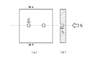
- an iron plate having two holes of the same shape formed on the back surface shown in FIGS. 2 (a) and 2 (b) is used as the inspection object 1-1. Detection was performed.
- This iron plate has a thickness of 10 mm, a size of 500 mm ⁇ 500 mm, a hole shape of ⁇ 30 mm (d shown in FIG. 2A), a depth of 6 mm (h shown in FIG. 2B), and a hole on the back surface (bottom surface). The hole is hidden on the surface.
- ten magnetic sensors are arranged in the magnetic sensor array 6-1, ten pieces of measurement data can be obtained at one time. By moving this in a predetermined direction and measuring it, a wider range of measurement data can be synthesized and obtained.
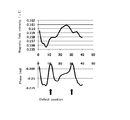
- FIG. 3 shows the result of measurement of the material to be inspected 1-1, showing the change in magnetic field strength (Bxi) at each point i, which is each measurement point in the magnetic sensors 7-1 to 10, and the change in phase ⁇ i.
- the horizontal axis of the upper graph is each point i
- the vertical axis is the magnetic field strength ( ⁇ T)
- the horizontal axis of the lower graph is each point i
- the vertical axis is the phase (rad).
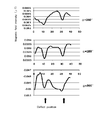
- FIG. 4 shows the result obtained by the analysis by the leakage magnetic flux flaw detection method of the present invention.
- the magnetic field strength Bxi ⁇ SIN ( ⁇ i + ⁇ ) at each point i is obtained, and here, the common adjustment phase ⁇ is set every 20 degrees. The result when changing to is shown.
- the defect is detected by observing the change in magnetic field strength and the change in phase independently.
- the present invention by multiplying the magnetic field intensity and the phase information as shown in FIG. 4 and further adjusting the common adjustment phase ⁇ , only the magnetic field change due to the defect can be extracted significantly.
- the common adjustment phase ⁇ is 180 degrees, a clear signal change (two downward peaks) corresponding to the position of the defect can be confirmed.
- the leakage magnetic flux flaw detector may be calibrated using a standard sample having no defect.
- an arbitrary value can be input to the signal analyzer 11 by an input unit (not shown) provided with a leakage magnetic flux flaw detector.
- the above-described leakage magnetic flux flaw detector includes scanning means for moving the magnetic sensor array 6-1 in a direction crossing the application direction of the alternating magnetic field, and in this embodiment, the application direction of the alternating magnetic field, By scanning and measuring in a direction perpendicular to the longitudinal direction of the magnetic sensor array, two-dimensional data of Bxi ⁇ SIN ( ⁇ i + ⁇ ) can be obtained, and a defect can be detected in two dimensions.
- the leakage magnetic flux flaw detector according to the present embodiment since the signal corresponding to the defect is obtained most when the common adjustment phase is 180 degrees, the signal is displayed as image data using this common adjustment phase. can do.
- the magnetic field applying means 15 and the magnetic sensor array 6-1 are integrally configured, and the magnetic field applying means 15 and the magnetic sensor array 6-1 can be moved integrally by providing a scanning means for the structure. You may comprise as follows.
- the leakage magnetic flux flaw detection device and the leakage magnetic flux flaw detection method applied to this leakage magnetic flux flaw detection device, it is possible to detect the magnetic field change corresponding to the position of the defect by detecting the parallel component of the leakage magnetic flux.
- the magnetic field signal due to the leakage magnetic flux obtained by the magnetic sensor array 6-1 is divided into two signals that are orthogonal to each other, the signal strength and the phase, and the phase at each measurement point measured at multiple points and all the phases
- a set of the exciting coils 2-1 and 2-2 can be connected to U or C.
- magnetic flux can be introduced into the material to be inspected 1-1 in parallel with the straight line connecting the pair of exciting coils 2-1 and 2-2.
- the magnetic flux leaking to the surface due to the defect of the material to be inspected 1-1 can be easily detected by the magnetic flux having good directivity, and the component in the same direction as the magnetic flux is measured as a magnetic sensor. Can be detected more significantly.
- arranging a plurality of magnetic sensors 7-1 to 10 side by side it is possible to inspect at a time without moving during the inspection.
- the leakage magnetic flux flaw detection apparatus is an apparatus for flaw detection by detecting a leakage magnetic flux leaking from the material to be inspected 1-2.
- the magnetic field application means 25 the magnetic sensor array, 6-2, mainly includes the lock-in detector 10, the signal analyzer 11, and the display mechanism 12 shown in FIG.
- the magnetic sensor array 6-2, the lock-in detector 10, the signal analysis device 11, and the display mechanism 12 are the same as those in the first embodiment, and detailed description thereof is omitted.
- the magnetic field applying means 25 is a magnetic field applying means for applying an alternating magnetic field to a cylindrical inspection object 1-2 (for example, a steel pipe) having a predetermined thickness, and a set of exciting coils 2-3, 2-4, An exciting coil power supply 4 and a transmitter 5 are included.
- the exciting coils 2-3 and 2-4 are examples of magnetic pole portions, and the exciting coils 2-3 and 2-4 are inspected in the exciting coils 2-3 and 2-4 with the surfaces of the exciting coils 2-3 and 2-4 facing each other.
- the material 1-2 can be inserted and arranged, and each is wound in an opposite winding.
- the exciting coils 2-3 and 2-4 are each connected to an exciting coil power source 4, and a transmitter 5 is connected to the exciting coil power source 4.
- the magnetic field applying means 25 excites the exciting coils 2-3, 2-4 by energizing the exciting coils 2-3, 2-4 with an alternating current from the exciting coil power source 4, and the exciting coils 2-3, 2-4 -4 is inserted through the material to be inspected 1-2, and a magnetic flux can be generated parallel to the surface of the material to be inspected 1-2 (in the x direction shown in FIG. 6).
- the magnetic sensor array 6-2 is a sensor for detecting a leakage magnetic flux leaking from the inspection object 1-2, and a plurality of magnetic sensors 7-1 to 10 are arranged in the longitudinal direction of the magnetic sensor array 6-2. It is an array sensor.
- the magnetic sensor array 6-2 is arranged on the surface of the inspection object 1-2 with a plurality of magnetic sensors 7-1 to 10 arranged in a direction parallel to the central axis of the excitation coils 2-3 and 2-4.
- the plurality of magnetic sensors 7-1 to -10 are placed in a magnetic field application direction of the magnetic field applying means 15 (center axes of the exciting coils 2-3 and 2-4) at a plurality of positions on the surface of the inspection object 1-2.
- the magnetic field component in the direction parallel to the direction parallel to (x direction) can be detected. That is, the magnetic sensor array 6-2 measures the magnitude of the magnetic field in a direction parallel to the magnetic field application direction of the magnetic field applying means 25 in the longitudinal direction of the magnetic sensor array 6-2 on the surface of the inspection object 1-2 at a plurality of points. can do.
- the plurality of magnetic sensors 7-1 to -10 are connected to the corresponding magnetic sensor measurement circuits 8-1 to 10, and the corresponding magnetic sensor 7-1 is connected to the magnetic sensor measurement circuits 8-1 to -10. ⁇ 10 are driven.
- the magnetic sensor measurement circuits 8-1 to 8-10 are connected to the multiplexer 9. Note that the winding shape of the exciting coils 2-3 and 2-4 is not particularly limited to a circular shape in front view as in this embodiment, and a shape appropriately corresponding to a cylindrical inspection object, for example, It can be oval or square.
- the surfaces of the pair of circular excitation coils 2-3 and 2-4 are opposed to each other, and the inspection object 1-2 which is a cylindrical steel pipe is connected to the excitation coils 2-3 and 2-4.
- the magnetic flux is introduced parallel to the central axis of the steel pipe.
- the magnetic sensors 7-1 to 10 for detecting the magnetic field component in the direction parallel to the central axis of the material to be inspected 1-2 are arranged in a number parallel to the central axis.
- Array 6-2 was used. With this configuration, it is possible to detect not only the surface of the cylindrical measurement object but also the inside of the measurement object or the internal surface of the pipe.
- a leakage magnetic flux flaw detection apparatus is configured, that is, by making the surfaces of a pair of the excitation coils 2-3 and 2-4 face each other, the excitation coils 2-3 and 2-4
- the material to be inspected 1-2 can be passed therethrough, and a magnetic flux can be introduced into the material to be inspected 1-2 in parallel with the central axis connecting the pair of exciting coils 2-3 and 2-4.
- the magnetic flux leaking to the surface due to the defect of the material to be inspected can be easily detected by the magnetic flux with good directivity, and the component in the same direction as the magnetic flux is measured as a magnetic sensor. Can be detected.
- a plurality of magnetic sensors 7-1 to 10 it is possible to inspect at a time without moving during the inspection.
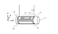
- FIG. 7 shows another form for providing the same function as the embodiment of FIG. 6 of the present invention.
- FIG. 6 in order to measure a cylindrical steel pipe, a structure in which the exciting coils 2-3 and 2-4 are wound around the cylinder is used.
- the exciting coils 2-3 and 2-4 are wound around the cylinder.
- FIG. 7 a plurality of rectangular exciting coils 13 having a predetermined size are combined and wound around the inspection object 1-3 (steel pipe), so that a magnetic field is applied to the inspection object 1-3.
- An exciting coil to be applied can be configured.
- each rectangular exciting coil 13 is formed on a plastic exciting coil base material 14, the rectangular exciting coil 13 can be closely matched to a cylindrical shape, and is formed on the cylindrical steel pipe surface of the material to be inspected 1-3. Can be pasted.
- the circular exciting coils 2-3 and 2-4 By connecting these in series in the circumferential direction of the material to be inspected 1-3, it is possible to have substantially the same function as the circular exciting coils 2-3 and 2-4 in FIG.
- the wiring portion of the excitation coil 13 arranged along the length direction of the cylinder overlaps with the wiring of the adjacent excitation coil 13. For this reason, the currents flowing in the exciting coils 13 are in the opposite directions to the adjacent exciting coils 13, so that they cancel each other.
- the wiring portions on the circumference of the exciting coil 13 are not overlapped, but are in the same direction as the direction of the current flowing in the adjacent exciting coil 13, so that the entire circumference of the cylindrical steel pipe is consequently obtained.
- Current can be formed.
- the magnetic field applying means shown in the present embodiment can have substantially the same functions of the exciting coils 2-3 and 2-4 as in FIG. 6, and the coils can be divided and pasted.
- An exciting coil that is very easy to remove can be realized.
- the leakage magnetic flux is a magnetic sensor array 6- in which a large number of magnetic sensors 7-1 to 10 for detecting a magnetic field component in a direction parallel to the central axis of the exciting coil (x direction) are arranged. 3 is used to measure.
- the leakage flux testing apparatus to which the leakage flux testing method according to the present invention is applied generates a magnetic flux parallel to the surface of the material to be inspected and detects the magnetic flux leaking from the surface of the object to be inspected by a magnetic sensor.
- a signal analysis device comprising lock-in detection means for detecting a signal having the same frequency as the excitation coil from the output of the measurement circuit, and analyzing the signal intensity and phase change of the output of the magnetic sensor by the output signal of the lock-in detection means
- the cosine or sine of the trigonometric function of the phase obtained by adding the phase at each measurement point measured at multiple points and the common adjustment phase at all measurement points is obtained, and the signal strength at each measurement point is obtained.
- the leakage flux testing apparatus to which the leakage flux testing method according to the present invention is applied can detect a magnetic field change corresponding to the position of the defect by detecting the parallel component of the leakage flux, and further, the magnetic field can be detected by the lock-in detection means.
- the signal is divided into signal strength and phase, and the cosine or sine of the trigonometric function of the phase obtained by adding the phase at each measurement point measured at multiple points and the common adjustment phase at all measurement points is obtained, and these signal strengths and trigonometric functions are obtained.
- the present invention is a leakage magnetic flux flaw detection method in which an AC magnetic field is applied to a measurement target of a steel structure to detect defects on the front surface, inside, or back surface.
- the conventional leakage magnetic flux flaw detection method has high accuracy in the surface defect inspection, but in the present invention, it is possible to inspect even deeper portions or defects on the back surface side. Thereby, it can apply to a defect inspection, such as an internal defect of a tank and piping in an industrial plant, and welding parts, such as a bridge.
Landscapes
- Chemical & Material Sciences (AREA)
- Chemical Kinetics & Catalysis (AREA)
- Electrochemistry (AREA)
- Physics & Mathematics (AREA)
- Health & Medical Sciences (AREA)
- Life Sciences & Earth Sciences (AREA)
- Analytical Chemistry (AREA)
- Biochemistry (AREA)
- General Health & Medical Sciences (AREA)
- General Physics & Mathematics (AREA)
- Immunology (AREA)
- Pathology (AREA)
- Investigating Or Analyzing Materials By The Use Of Magnetic Means (AREA)
Abstract
【課題】漏洩磁束探傷方法において、測定した結果が測定状態の変動に影響されることなく、欠陥による真の信号が精度良くとらえられる計測及び解析方法を提供する。 【解決手段】被検査材表面に平行な磁束を発生させ、被検査体表面から漏洩する磁束を磁気センサによって検知する漏洩磁束探傷方法において、周波数が可変の交流磁場を発生させる励磁コイルと、励磁コイル用電源と、被検査体表面から漏洩した磁場の表面に水平な成分を検知する磁気センサと、磁気センサの出力から励磁コイルと同じ周波数の信号を検波するロックイン検波回路と、ロックイン検波回路の出力信号により磁気センサの出力の信号強度と位相変化を解析する信号解析装置を備え、多点計測した各計測点の位相と全ての計測点で共通の調整位相を足し合わせた位相の三角関数の余弦あるいは正弦を求め、各計測点での信号強度と正弦あるいは余弦をかけあわせた解析値を任意での調整位相で表示する。
Description
本発明は、被検査材に交流磁場を印加し、被検査材表面から漏洩する漏洩磁束を検出することによって被検査材の欠陥を探傷する方法及び装置に関する。
従来、鋼材の欠陥を検査する方法として、磁気を用いた漏洩磁束探傷方法がある。これは、測定対象を直流あるいは交流によって磁化させて、測定対象の表面から漏洩する磁束を主に磁気センサとしてサーチコイルで検出している。最近では、当該磁気センサとして磁気抵抗素子(MR)、ホール素子、磁気インピーダンス素子(MI)なども用いられ始めている。上記磁気を用いた漏洩磁束探傷方法では、測定対象である鋼材を直流あるいは交流によって磁化させた場合、鋼材表面に欠陥があると表面に漏洩磁束が発生するので、当該漏洩磁束の表面に平行な磁場成分あるいは垂直な磁場成分を磁気センサによって計測する。ここで、測定対象を磁化させる方法としては、励磁コイルによって直流に磁化させる方法と、交流に磁化させる方法がある。直流に磁化させる方法では、測定対象断面を一様に磁化させることができるので内部の欠陥を探傷する方法として主に用いられている。また、交流に磁化させる方法では、周波数に依存した表皮効果を有するので主に材料表面近くでの探傷に用いられている。また、MRや、ホール素子、MI素子などの低周波まで感度がある磁気センサは、低周波で励磁することができるので、測定対象の深部の欠陥を検出する際に適用される。漏洩磁束探傷方法は、一般的に渦電流探傷方法に含まれる。渦電流探傷方法と漏洩磁束探傷方法とは、同じ構成の探傷方法であり、測定対象に磁場を印加して磁気センサで計測する方法である。また、低周波磁場を印加して、試料表面に平行な磁場成分を検出する渦電流探傷方法については、特許第3987941号公報(特許文献1)に記載されている。
測定対象としては様々な形状があるが、円柱状の鋼管や棒鋼などの欠陥を検出する場合には、励磁コイルとして貫通型コイルに測定対象を通して、交流磁化をする方法が良く行われている。また、大きな鋼管やタンクなどを検査する場合には、表面が平坦に近いため、Uの字の形状のヨーク材に励磁コイルを取り付け、ヨーク材両端の部分を測定対象に接触させ交流で磁化させる方法がよくとられている(非特許文献1、2参照)。
このような漏洩磁束探傷で測定対象の様々な位置で計測して得られた、多点計測データの処理として従来は、磁気センサの出力をそのまま信号強度として用い、計測位置による信号強度変化を見ることにより、欠陥部分や大きさを推定していた。また、最近では、磁気センサの出力を、励磁コイルと同期させてロックインアンプによって検波し、信号強度の他、位相を解析することが行われている。すなわち、計測位置による信号強度変化の他、位相変化をグラフ化して欠陥部分や大きさを推定している。例えば特開2007-64628号公報(特許文献2)では信号強度変化のグラフから、欠陥の深さと、大きさを同定する解析方法が記載されている。
「Non-destructive evaluation ofmagnetic metallic materials using Hallsensors」K.Kosmas,Ch. Sargentis,D.Tsamakis,E.Hristoforou,Journal of Materials Processing Technology, Vol.161(2005)pp.359-362
「非線形渦電流解析による欠陥検査法」 後藤雄治,電気学会誌,127巻(2007)pp.727-730
上述したように、従来の漏洩磁束探傷方法では、測定した範囲での磁場強度変化や位相の変化をそれぞれ独自にグラフ化あるいはマッピングして、欠陥を検出し表示していた。しかし、これらの解析表示では、測定のための走査を行っているときに測定試料と、測定装置の励磁コイルや磁気センサとの距離が一定でない場合、その変動分が測定結果に大きく影響してしまうため、正確な欠陥位置や大きさを同定することが困難になることがあった。
そこで、本発明は、測定した結果が測定状態の変動に影響されることなく、欠陥による真の信号が精度良くとらえられる計測及び解析をするための漏洩磁束探傷方法及び装置を提供することを目的とする。
本発明は、
被検査材に交流磁場を印加する磁場印加手段と、
前記被検査材から漏洩する漏洩磁束を検出するセンサと、
前記センサから出力された信号と位相の変化を解析する解析手段と、
を用い、前記被検査材から漏洩する漏洩磁束を検出することにより欠陥を探傷する漏洩磁束探傷方法であって、
前記磁場印加手段により前記交流磁場を所定の磁場印加方向に印加して前記被検査材の表面と平行な磁束を生じさせる工程と、
前記センサにより前記被検査材の表面の複数位置における前記所定の磁場印加方向と平行な方向の磁場の大きさを検出する工程と、
前記センサの出力を前記交流磁場と同じ周波数で位相が互いに直交する2つの信号に検波して前記解析手段に入力する工程と、
前記解析手段に入力された前記2つの信号によって、前記複数位置における磁場の大きさのデータと前記位相のデータを算出し、当該位相に対して校正用の補正位相を加えたデータの正弦値あるいは余弦値を求め、前記磁場の大きさのデータと前記正弦値あるいは前記余弦値との積を求め、前記複数位置における前記積の各値を用いて欠陥を特定する工程と、を備え、
前記欠陥を特定する工程において、
前記校正用の補正位相は、前記複数位置における前記位相に対して共通して加えることで前記位相を調整する共通の調整位相であり、
前記複数位置における前記積の各値は、前記共通の調整位相を任意に変化させて求められる前記複数位置における前記積の各値のうち、前記欠陥による磁場変化のみが抽出され得る共通の調整位相の時の前記複数位置における前記積の各値である漏洩磁束探傷方法である。
被検査材に交流磁場を印加する磁場印加手段と、
前記被検査材から漏洩する漏洩磁束を検出するセンサと、
前記センサから出力された信号と位相の変化を解析する解析手段と、
を用い、前記被検査材から漏洩する漏洩磁束を検出することにより欠陥を探傷する漏洩磁束探傷方法であって、
前記磁場印加手段により前記交流磁場を所定の磁場印加方向に印加して前記被検査材の表面と平行な磁束を生じさせる工程と、
前記センサにより前記被検査材の表面の複数位置における前記所定の磁場印加方向と平行な方向の磁場の大きさを検出する工程と、
前記センサの出力を前記交流磁場と同じ周波数で位相が互いに直交する2つの信号に検波して前記解析手段に入力する工程と、
前記解析手段に入力された前記2つの信号によって、前記複数位置における磁場の大きさのデータと前記位相のデータを算出し、当該位相に対して校正用の補正位相を加えたデータの正弦値あるいは余弦値を求め、前記磁場の大きさのデータと前記正弦値あるいは前記余弦値との積を求め、前記複数位置における前記積の各値を用いて欠陥を特定する工程と、を備え、
前記欠陥を特定する工程において、
前記校正用の補正位相は、前記複数位置における前記位相に対して共通して加えることで前記位相を調整する共通の調整位相であり、
前記複数位置における前記積の各値は、前記共通の調整位相を任意に変化させて求められる前記複数位置における前記積の各値のうち、前記欠陥による磁場変化のみが抽出され得る共通の調整位相の時の前記複数位置における前記積の各値である漏洩磁束探傷方法である。
本発明は、前記積の各値を、表示手段により表示する工程を有する漏洩磁束探傷方法である。
本発明は、
被検査材に交流磁場を印加する磁場印加手段と、
前記被検査材から漏洩する漏洩磁束を検出するセンサと、
前記センサから出力された信号と位相の変化を解析する解析手段と、
を備え、前記被検査材から漏洩する漏洩磁束を検出することにより欠陥を探傷する漏洩磁束探傷装置であって、
前記センサの出力を前記交流磁場と同じ周波数で位相が互いに直交する2つの信号に検波するロックイン検波手段を備え、
前記磁場印加手段では、前記交流磁場を所定の磁場印加方向に印加して前記被検査材の表面と平行な磁束を生じさせ、
前記センサは、前記被検査材の表面の複数位置における前記所定の磁場印加方向と平行な方向の磁場の大きさを検出し、
前記解析手段は、前記2つの信号によって、前記複数の位置における磁場の大きさのデータと前記位相のデータを算出し、当該位相に対して校正用の補正位相を加えたデータの正弦値あるいは余弦値を求め、前記磁場の大きさのデータと前記正弦値あるいは前記余弦値との積を求め、前記複数位置における前記積の各値を用いて欠陥を特定し、
前記校正用の補正位相は、前記複数位置における前記位相に対して共通して加えることで前記位相を調整する共通の調整位相であり、
前記複数位置における前記積の各値は、前記共通の調整位相を任意に変化させて求められる前記複数位置における前記積の各値のうち、前記欠陥による磁場変化のみが抽出され得る共通の調整位相の時の前記複数位置における前記積の各値である漏洩磁束探傷装置である。
被検査材に交流磁場を印加する磁場印加手段と、
前記被検査材から漏洩する漏洩磁束を検出するセンサと、
前記センサから出力された信号と位相の変化を解析する解析手段と、
を備え、前記被検査材から漏洩する漏洩磁束を検出することにより欠陥を探傷する漏洩磁束探傷装置であって、
前記センサの出力を前記交流磁場と同じ周波数で位相が互いに直交する2つの信号に検波するロックイン検波手段を備え、
前記磁場印加手段では、前記交流磁場を所定の磁場印加方向に印加して前記被検査材の表面と平行な磁束を生じさせ、
前記センサは、前記被検査材の表面の複数位置における前記所定の磁場印加方向と平行な方向の磁場の大きさを検出し、
前記解析手段は、前記2つの信号によって、前記複数の位置における磁場の大きさのデータと前記位相のデータを算出し、当該位相に対して校正用の補正位相を加えたデータの正弦値あるいは余弦値を求め、前記磁場の大きさのデータと前記正弦値あるいは前記余弦値との積を求め、前記複数位置における前記積の各値を用いて欠陥を特定し、
前記校正用の補正位相は、前記複数位置における前記位相に対して共通して加えることで前記位相を調整する共通の調整位相であり、
前記複数位置における前記積の各値は、前記共通の調整位相を任意に変化させて求められる前記複数位置における前記積の各値のうち、前記欠陥による磁場変化のみが抽出され得る共通の調整位相の時の前記複数位置における前記積の各値である漏洩磁束探傷装置である。
本発明は、前記校正用の補正位相を入力する入力手段を備えた漏洩磁束探傷装置である。
本発明は、前記センサを前記交流磁場の印加方向と交差する方向に移動させる走査手段を設けた漏洩磁束探傷装置である。
本発明は、前記磁場印加手段は2つの磁極部を有し、この2つの磁極部間に複数の前記センサを並べて設けた漏洩磁束探傷装置である。
本発明は、前記2つの磁極部が一組の励磁コイルであり、当該励磁コイルの面を対向配置し、前記励磁コイルの中に被検査材を挿通可能とするとともに、前記励磁コイルの中心軸に対して平行な方向に複数の前記センサを並べて設けた漏洩磁束探傷装置である。
本発明によれば、漏洩磁束の平行成分を検知することにより欠陥の位置と対応した磁場変化をとらえることができ、さらにセンサにより得られた漏洩磁束による磁場信号を互いに直交する2つの信号である信号強度と位相に分け、複数位置で多点計測した各計測点での位相と全ての計測点で校正用の補正位相を足し合わせた位相の三角関数の余弦あるいは正弦を求め、これら信号強度と三角関数をかけた量を求めることによって、最適な信号変化を求めることができ、より正確な欠陥位置や大きさを同定することが可能となる。
本発明によれば、前記積の各値を表示手段により表示することによって、前記補正位相を任意に変化させた場合に最適な信号変化を容易に求めることができ、より正確な欠陥位置や大きさを同定することが可能となる。
本発明によれば、漏洩磁束の平行成分を検知することにより欠陥の位置と対応した磁場変化をとらえることができ、さらにロックイン検波手段によりセンサにより得られた磁場信号を信号強度と位相に分け、複数位置で多点計測した各計測点での位相と全ての計測点で校正用の補正位相を足し合わせた位相の三角関数の余弦あるいは正弦を求め、これら信号強度と三角関数をかけた量を求めることによって、最適な信号変化を求めることができ、より正確な欠陥位置や大きさを同定することが可能となる。
本発明によれば、前記補正位相を任意に入力可能となる。
本発明によれば、二次元で欠陥を検出することができる。
本発明によれば、複数個のセンサを並べることにより、検査時に磁極部間におけるセンサの移動が不要となり、測定状態の変動に影響されることなく一度に検査することが可能となる。
本発明によれば、一組の該励磁コイルの面を対向させることにより、該励磁コイルの中に被検査材を通すことができ、一組の励磁コイルを結んだ中心軸と平行に、被検査材に磁束を導入することができる。このように方向性のよい磁束により被検査材の欠陥によって表面に漏洩した磁束を検知しやすくなり、さらにセンサとして磁束と同じ方向の成分を計測するため、欠陥による漏洩磁束の変化をより顕著に検出することができる。また、複数個のセンサを並べることにより、検査時に磁極部間におけるセンサの移動が不要となり、測定状態の変動に影響されることなく一度に検査することが可能となる。
1-1 被検査材
1-2 被検査材
1-3 被検査材
2-1 励磁コイル
2-2 励磁コイル
2-3 励磁コイル
2-4 励磁コイル
3 ヨーク材
4 励磁コイル用電源
5 発信器
6-1 磁気センサアレイ
6-2 磁気センサアレイ
6-3 磁気センサアレイ
7-1 磁気センサ
7-2 磁気センサ
7-3 磁気センサ
7-4 磁気センサ
7-5 磁気センサ
7-6 磁気センサ
7-7 磁気センサ
7-8 磁気センサ
7-9 磁気センサ
7-10 磁気センサ
8-1 磁気センサ計測回路
8-2 磁気センサ計測回路
8-3 磁気センサ計測回路
8-4 磁気センサ計測回路
8-5 磁気センサ計測回路
8-6 磁気センサ計測回路
8-7 磁気センサ計測回路
8-8 磁気センサ計測回路
8-9 磁気センサ計測回路
8-10 磁気センサ計測回路
9 マルチプレクサ
10 ロックイン検波器
11 信号解析装置
12 表示機構
13 長方形励磁コイル
14 励磁コイル母材
15・25 磁場印加手段
1-2 被検査材
1-3 被検査材
2-1 励磁コイル
2-2 励磁コイル
2-3 励磁コイル
2-4 励磁コイル
3 ヨーク材
4 励磁コイル用電源
5 発信器
6-1 磁気センサアレイ
6-2 磁気センサアレイ
6-3 磁気センサアレイ
7-1 磁気センサ
7-2 磁気センサ
7-3 磁気センサ
7-4 磁気センサ
7-5 磁気センサ
7-6 磁気センサ
7-7 磁気センサ
7-8 磁気センサ
7-9 磁気センサ
7-10 磁気センサ
8-1 磁気センサ計測回路
8-2 磁気センサ計測回路
8-3 磁気センサ計測回路
8-4 磁気センサ計測回路
8-5 磁気センサ計測回路
8-6 磁気センサ計測回路
8-7 磁気センサ計測回路
8-8 磁気センサ計測回路
8-9 磁気センサ計測回路
8-10 磁気センサ計測回路
9 マルチプレクサ
10 ロックイン検波器
11 信号解析装置
12 表示機構
13 長方形励磁コイル
14 励磁コイル母材
15・25 磁場印加手段
以下、本発明の実施形態を、添付する図面を参照して詳細に説明する。
また、同様の用途及び機能を有する部材には同符号を付してその説明を省略する。
また、同様の用途及び機能を有する部材には同符号を付してその説明を省略する。
図1は、本発明の一実施形態である漏洩磁束探傷方法を適用する漏洩磁束探傷装置の基本構成を示す概略図である。
漏洩磁束探傷装置は、被検査材1-1から漏洩する漏洩磁束を検出することにより欠陥を探傷する装置である。漏洩磁束探傷装置は、図1に示すように、磁場印加手段15、磁気センサアレイ6-1、ロックイン検波器10、信号解析装置11及び表示機構12を主に具備している。
漏洩磁束探傷装置は、被検査材1-1から漏洩する漏洩磁束を検出することにより欠陥を探傷する装置である。漏洩磁束探傷装置は、図1に示すように、磁場印加手段15、磁気センサアレイ6-1、ロックイン検波器10、信号解析装置11及び表示機構12を主に具備している。
磁場印加手段15は、所定の厚みを有する被検査材1-1に交流磁場を印加する磁場印加手段であり、一組の励磁コイル2-1、2-2、ヨーク材3、励磁コイル用電源4及び発信器5により構成される。励磁コイル2-1、2-2は、磁極部の一例であり、U字型の前記ヨーク材3の両端部に各々反対巻きに巻回されている。また、励磁コイル2-1、2-2は、それぞれ励磁コイル用電源4に接続されており、当該励磁コイル用電源4には発信器5が接続されている。磁場印加手段15は、励磁コイル用電源4により交流電流を励磁コイル2-1、2-2に通電することで励磁コイル2-1、2-2を励磁し、当該励磁コイル2-1、2-2を被検査材1-1表面に接触させることで前記被検査材1-1の表面と平行となるように磁束を生じさせることができる。つまり、磁場印加手段15は、交流磁場を所定の磁場印加方向(本実施例においては、励磁コイル2-1、2-2間を結ぶ直線と平行な方向)に印加して被検査材の表面と平行な磁束を発生させることができる。
なお、前記ヨーク材3の形状はU字型に限定するものでなく、コの字型であってもかまわない。
なお、前記ヨーク材3の形状はU字型に限定するものでなく、コの字型であってもかまわない。
磁気センサアレイ6-1は、前記被検査材1-1から漏洩する漏洩磁束を検出するセンサであり、複数の磁気センサ7-1~10を磁気センサアレイ6-1の長手方向に並べて設けたアレイ状のセンサである。磁気センサアレイ6-1は、前記励磁コイル2-1、2-2間を結ぶ直線に平行な方向に複数の磁気センサ7-1~10を並べた状態で被検査材1-1表面に載置され、前記複数の磁気センサ7-1~10は被検査材1-1の表面の複数位置における、磁場印加手段15の磁場印加方向(前記励磁コイル2-1、2-2間を結ぶ直線上に平行な方向)と平行な方向の磁場成分を検出することができる。すなわち、磁気センサアレイ6-1は、被検査材1-1の表面の磁気センサアレイ6-1長手方向における磁場印加手段15の磁場印加方向と平行な方向の磁場の大きさを複数点で計測することができる。また、複数の磁気センサ7-1~10は、それぞれに対応する磁気センサ計測回路8-1~10に接続されており、当該磁気センサ計測回路8-1~10により対応する磁気センサ7-1~10が駆動される。磁気センサ計測回路8-1~10は、マルチプレクサ9に接続されている。
ロックイン検波器10は、磁気センサアレイ6-1の出力信号を前記交流磁場と同じ周波数で位相が互いに直交する2つの信号に検波するロックイン検波手段である。ロックイン検波器10は、励磁コイル2-1、2-2に流された交流電流の交流周波数に同期した信号のみを検出する。つまり、ロックイン検波器10は、励磁コイル2-1、2-2と同じ周波数で位相が互いに90度異なる2つの信号に検波する。ロックイン検波器10は、マルチプレクサ9に接続されている。
信号解析装置11は、前記磁気センサアレイ6-1から前記ロックイン検波器10を介して出力された信号と位相の変化を解析する手段であり、前記ロックイン検波器10に接続されている。すなわち、信号解析装置11は、ロックイン検波器10により検波された2つの信号によって、複数の位置における磁場の大きさのデータと前記位相のデータを算出し、当該位相に対して校正用の補正位相を加えたデータの正弦値あるいは余弦値を求め、前記磁場の大きさのデータと前記正弦値あるいは前記余弦値との積を求め、前記複数位置における前記積の各値を用いて欠陥を特定することができる。つまり、信号解析装置11は、ロックイン検波器10によって検波された信号を所定の解析方法により解析することができる。信号解析装置11には、表示機構12が接続されている。
また、信号解析装置11には、前記校正用の補正位相を入力する入力手段(図示せず)が接続されている。
ここで、前記校正用の補正位相とは、磁気センサアレイ6-1の校正を行う際に、磁気センサアレイ6-1が有する複数の磁気センサ7-1~10全てに対して共通して適用される位相調整用の位相のことである(以下、共通の調整位相αという)。
また、信号解析装置11には、前記校正用の補正位相を入力する入力手段(図示せず)が接続されている。
ここで、前記校正用の補正位相とは、磁気センサアレイ6-1の校正を行う際に、磁気センサアレイ6-1が有する複数の磁気センサ7-1~10全てに対して共通して適用される位相調整用の位相のことである(以下、共通の調整位相αという)。
表示機構12は、前記信号解析装置11により解析結果を表示する表示手段である。表示機構12は、例えば、前記ロックイン検波器10を介して出力された信号と位相の変化や前記磁場の大きさのデータと前記正弦値あるいは前記余弦値との積の値のような被検査材1-1表面の欠陥を特定する際に必要な情報を表示することができる。
また、上述した漏洩磁束探傷装置に適用する本実施形態に係る漏洩磁束探傷方法は、
上記漏洩磁束探傷装置を用い、前記被検査材1-1から漏洩する漏洩磁束を検出することにより欠陥を探傷する漏洩磁束探傷方法であって、
前記磁場印加手段15により前記交流磁場を所定の磁場印加方向に印加して前記被検査材1-1の表面と平行な磁束を生じさせる工程と、
前記磁気センサアレイ6-1により前記被検査材1-1の表面の複数位置における前記所定の磁場印加方向と平行な方向の磁場の大きさを検出する工程と、
前記磁気センサアレイ6-1の出力を前記交流磁場と同じ周波数で位相が互いに直交する2つの信号に検波して前記信号解析装置11に入力する工程と、
前記信号解析装置11に入力された前記2つの信号によって、前記複数位置における磁場の大きさのデータと前記位相のデータを算出し、当該位相に対して共通の調整位相αを加えたデータの正弦値あるいは余弦値を求め、前記磁場の大きさのデータと前記正弦値あるいは前記余弦値との積を求め、前記複数位置における前記積の各値を用いて欠陥を特定する工程と、を備えたものである。
以下、漏洩磁束探傷装置及び漏洩磁束探傷方法を具体的に説明する。
上記漏洩磁束探傷装置を用い、前記被検査材1-1から漏洩する漏洩磁束を検出することにより欠陥を探傷する漏洩磁束探傷方法であって、
前記磁場印加手段15により前記交流磁場を所定の磁場印加方向に印加して前記被検査材1-1の表面と平行な磁束を生じさせる工程と、
前記磁気センサアレイ6-1により前記被検査材1-1の表面の複数位置における前記所定の磁場印加方向と平行な方向の磁場の大きさを検出する工程と、
前記磁気センサアレイ6-1の出力を前記交流磁場と同じ周波数で位相が互いに直交する2つの信号に検波して前記信号解析装置11に入力する工程と、
前記信号解析装置11に入力された前記2つの信号によって、前記複数位置における磁場の大きさのデータと前記位相のデータを算出し、当該位相に対して共通の調整位相αを加えたデータの正弦値あるいは余弦値を求め、前記磁場の大きさのデータと前記正弦値あるいは前記余弦値との積を求め、前記複数位置における前記積の各値を用いて欠陥を特定する工程と、を備えたものである。
以下、漏洩磁束探傷装置及び漏洩磁束探傷方法を具体的に説明する。
図1に示すように、被検査材1-1表面に、励磁コイル2-1、2-2を接触させた状態で、当該励磁コイル2-1、2-2により交流磁場を所定の印加方向(励磁コイル2-1、2-2を結ぶ直線と平行な方向)に印加して、前記被検査材1-1の表面と平行な磁束が導入される。この一組の励磁コイル2-1、2-2はUの字型のヨーク材3の両端に取り付けており、この両端を結んだ直線の方向に磁束を導入することができる。励磁コイル用電源4は発信器5によって励磁の周波数を変えることができる。この発信器5の信号で励磁コイル用電源4を駆動し励磁コイル2-1と2-2に交流電流を流す。励磁コイル2-1と2-2は反対巻きになっており、片方が被検査材1-1に対してN極になり、もう一方は被検査材1-1に対してS極となるように構成されている。被検査材1-1の表面あるいは内部あるいは裏面に欠陥があると、その直上において漏洩磁束が漏洩し、磁場が変化する。この変化を磁気センサアレイ6-1で多点計測を行う。この磁気センサアレイ6-1が有する磁気センサ7-1~10は、励磁コイル2-1、2-2が対向する方向と同方向、つまり磁束を導入したx方向に配列されている。また、磁気センサアレイ6-1の各磁気センサ7-1~10は、磁気センサアレイ6-1の長手方向、つまり磁束を導入した方向の漏洩磁束の磁束密度成分Bxを検出している。この磁束密度成分Bxを計測する磁気センサとしては磁気抵抗素子(MR)を用いた。もちろん、磁気センサとして他の磁気インピーダンス素子(MI)や、ホール素子、フラックスゲート、超伝導量子干渉素子等いずれかを使用することもできる。
磁気センサアレイ6-1には10個の磁気センサ7-1~10を並べて設けた。もちろん、磁気センサの数が多く、また磁気センサ間隔を小さくすることにより空間分解能が高い測定が可能となる。また、複数個の磁気センサ7-1~10を並べることにより、検査時に励磁コイル2-1と2-2の間の移動(走査)が不要となり、測定状態の変動に影響されることなく一度に検査することが可能となる。磁気センサ7-1~10にはそれぞれ計測用として磁気センサ計測回路8-1~10を設けて、これらの各出力をマルチプレクサ9によって切り替えてロックイン検波器10によって検波する。この検波により励磁コイル2-1と2-2に流す交流電流の信号を作っている発信器5に同期した信号だけを検出することができる。そして、発信器5の信号に対する同相の信号と、90度位相がずれている信号が、ロックイン検波器10によって2つに分離して検出される。この同相信号と直交信号によって、磁気センサアレイ6-1における各磁気センサ7-1~10の信号の信号強度Bxiと位相θiを算出することができる。信号解析装置11においてBxi・SIN(θi+α)を計算し、データを表示機構12に表示する。ここで、このデータを見ながら解析処理を進め、共通の調整位相αを変化させ、最適な最終表示を行う。すなわち、この最適な最終表示を行うことにより、共通の調整位相αを任意に変化させた場合に最適な信号変化を容易に求めることができ、より正確な欠陥位置や大きさを同定することが可能となる。
なお、上述した共通の調整位相αを変化させて、欠陥位置や大きさを検出するための最適なBxi・SIN(θi+α)を求める方法としては、Bxi・SIN(θi+α)として所定の閾値を予め設定しておき、信号解析装置11が有する図示しない演算手段により所定のプログラムを実行して自動的に求めることも可能である。
なお、上述した共通の調整位相αを変化させて、欠陥位置や大きさを検出するための最適なBxi・SIN(θi+α)を求める方法としては、Bxi・SIN(θi+α)として所定の閾値を予め設定しておき、信号解析装置11が有する図示しない演算手段により所定のプログラムを実行して自動的に求めることも可能である。
次に、漏洩磁束探傷装置の基本性能を示すため、被検査材1-1として図2(a)(b)に示す裏面に同じ形状の2つの穴が穿設された鉄板を用いて欠陥の検出を行った。この鉄板は板厚10mm、大きさ500mm×500mmで、穴形状としてφ30mm(図2(a)に示すd)、深さ6mm(図2(b)に示すh)で裏面(底面)に穴があいていて表面においては穴が隠れた状態である。これを被検査材1-1の表面(矢印S側)から、図1の漏洩磁束探傷方法を適用した漏洩磁束探傷装置を用いて計測した。ここで、磁気センサアレイ6-1には磁気センサが10個配置しているので、一度に10点の計測データが得られる。これをさらに所定方向に移動させて計測することによって、もっと広い範囲の計測データを合成して得ることができる。
図3は被検査材1-1を測定した結果を示し、磁気センサ7-1~10における各計測点である各点iにおける磁場強度(Bxi)変化と、位相θi変化を示している。図3において、上グラフの横軸が各点i、縦軸が磁場強度(μT)であり、下グラフの横軸が各点i、縦軸が位相(rad)である。また、図4は本発明の漏洩磁束探傷方法による解析によって得られる結果を示しており、各点iにおける磁場強度Bxi・SIN(θi+α)を求め、ここで、共通の調整位相αを20度毎に変化させた時の結果を示したものである。従来は図3のように磁場強度変化や位相変化をそれぞれ単独で見て欠陥を検出していた。一方、本発明では図4のように磁場強度と位相情報を掛け合わせることによって、さらに共通の調整位相αを調整することにより欠陥による磁場変化のみが顕著に抽出できるようになる。ここで、図4では共通の調整位相αが180度の時、欠陥の位置に対応した明確な信号変化(2つの下向きピーク)を確認することができている。この共通の調整位相αはいったん決定されれば、各計測時に調整する必要は特になく、欠陥のない標準サンプルなどを使って漏洩磁束探傷装置を校正しておけばよい。
なお、前記共通の調整位相αとしては、漏洩磁束探傷装置の設けられた図示しない入力手段により任意の値を信号解析装置11に入力することが可能である。
なお、前記共通の調整位相αとしては、漏洩磁束探傷装置の設けられた図示しない入力手段により任意の値を信号解析装置11に入力することが可能である。
また、図示しないが、上述した漏洩磁束探傷装置においては、磁気センサアレイ6-1を交流磁場の印加方向と交差する方向に移動させる走査手段を設け、交流磁場の印加方向、すなわち本実施例では磁気センサアレイの長手方向に対して垂直方向に走査して計測することによりBxi・SIN(θi+α)の2次元のデータを得て、欠陥を二次元で検出することができる。上述したように本実施例に係る漏洩磁束探傷装置においては、共通の調整位相が180度の場合において最も欠陥に対応した信号が得られたので、この共通の調整位相を用いて画像データとして表示することができる。図5は、図2の片方の穴を中心とした走査範囲100mm×100mmで計測した結果を示しており、穴の大きさに対応した画像が得られている。このように本発明により従来困難であった被検査材の裏面の欠陥も精度良く検知できるようになった。
なお、磁場印加手段15と磁気センサアレイ6-1とを一体的に構成し、これに走査手段を設けることで、磁場印加手段15と磁気センサアレイ6-1とを一体として移動することができるように構成してもかまわない。
なお、磁場印加手段15と磁気センサアレイ6-1とを一体的に構成し、これに走査手段を設けることで、磁場印加手段15と磁気センサアレイ6-1とを一体として移動することができるように構成してもかまわない。
以上のように、漏洩磁束探傷装置及びこの漏洩磁束探傷装置に適用する漏洩磁束探傷方法を構成することで、漏洩磁束の平行成分を検知することにより欠陥の位置と対応した磁場変化をとらえることができ、さらに磁気センサアレイ6-1により得られた漏洩磁束による磁場信号を互いに直交する2つの信号である信号強度と位相に分け、複数位置で多点計測した各計測点での位相と全ての計測点で共通の調整位相αを足し合わせた位相の三角関数の余弦あるいは正弦を求め、これら信号強度と三角関数をかけた量を求めることによって、欠陥を検出しやすい最適な信号変化を求めることができ、より正確な欠陥位置や大きさを同定することが可能となる。
また、本実施例のように、漏洩磁束探傷装置及びこの漏洩磁束探傷装置に適用する漏洩磁束探傷方法を構成することで、一組の該励磁コイル2-1、2-2をUあるいはコの字型のヨーク材3の両端部に設けことにより、一組の励磁コイル2-1、2-2を結んだ直線と平行に、被検査材1-1に磁束を導入することができる。このように方向性のよい磁束により被検査材1-1の欠陥によって表面に漏洩した磁束を検知しやすくなり、さらに磁気センサとして磁束と同じ方向の成分を計測するため、欠陥による漏洩磁束の変化をより顕著に検出することができる。また、複数個の磁気センサ7-1~10を並べて配置することにより、検査時に移動をしなくても一度に検査することが可能となる。
次に、本発明に係る漏洩磁束探傷方法を適用する漏洩磁束探傷装置の別実施例について図6を用いて説明する。
本実施例に係る漏洩磁束探傷装置は、被検査材1-2から漏洩する漏洩磁束を検出することにより欠陥を探傷する装置であり、図6に示すように、磁場印加手段25、磁気センサアレイ6-2、図1で示した、ロックイン検波器10、信号解析装置11及び表示機構12を主に具備している。磁気センサアレイ6-2、ロックイン検波器10、信号解析装置11及び表示機構12については、実施例1と同様であり、詳細な説明は省略する。
本実施例に係る漏洩磁束探傷装置は、被検査材1-2から漏洩する漏洩磁束を検出することにより欠陥を探傷する装置であり、図6に示すように、磁場印加手段25、磁気センサアレイ6-2、図1で示した、ロックイン検波器10、信号解析装置11及び表示機構12を主に具備している。磁気センサアレイ6-2、ロックイン検波器10、信号解析装置11及び表示機構12については、実施例1と同様であり、詳細な説明は省略する。
磁場印加手段25は、所定の厚みを有する円筒状の被検査材1-2(例えば、鋼管)に交流磁場を印加する磁場印加手段であり、一組の励磁コイル2-3、2-4、励磁コイル用電源4及び発信器5により構成される。励磁コイル2-3、2-4は、磁極部の一例であり、当該励磁コイル2-3、2-4の面が対向した状態で前記励磁コイル2-3、2-4の中に被検査材1-2を挿通して配置することが可能であり、各々反対巻きに巻回されている。また、励磁コイル2-3、2-4は、それぞれ励磁コイル用電源4に接続されており、当該励磁コイル用電源4には発信器5が接続されている。磁場印加手段25は、励磁コイル用電源4より交流電流を励磁コイル2-3、2-4に通電することで励磁コイル2-3、2-4を励磁し、当該励磁コイル2-3、2-4に被検査材1-2を挿通させて配置することで前記被検査材1-2の表面と平行に(図6に示すx方向に)磁束を生じさせることができる。
磁気センサアレイ6-2は、前記被検査材1-2から漏洩する漏洩磁束を検出するセンサであり、複数の磁気センサ7-1~10を磁気センサアレイ6-2の長手方向に並べて設けたアレイ状のセンサである。磁気センサアレイ6-2は、前記励磁コイル2-3、2-4の中心軸に対して平行な方向に複数の磁気センサ7-1~10を並べた状態で被検査材1-2表面に載置され、前記複数の磁気センサ7-1~10は被検査材1-2の表面の複数位置における、磁場印加手段15の磁場印加方向(前記励磁コイル2-3、2-4の中心軸に平行な方向:x方向)と平行な方向の磁場成分を検出することができる。すなわち、磁気センサアレイ6-2は、被検査材1-2の表面の磁気センサアレイ6-2長手方向における磁場印加手段25の磁場印加方向と平行な方向の磁場の大きさを複数点で計測することができる。また、複数の磁気センサ7-1~10は、それぞれに対応する磁気センサ計測回路8-1~10に接続されており、当該磁気センサ計測回路8-1~10により対応する磁気センサ7-1~10が駆動される。磁気センサ計測回路8-1~10は、マルチプレクサ9に接続されている。
なお、前記励磁コイル2-3、2-4の巻回形状は、本実施例の如く、正面視円形状に特に限定するものでなく、筒状の被検査材に適宜対応させた形状、例えば楕円状や四角状とすることができる。
なお、前記励磁コイル2-3、2-4の巻回形状は、本実施例の如く、正面視円形状に特に限定するものでなく、筒状の被検査材に適宜対応させた形状、例えば楕円状や四角状とすることができる。
つまり、本実施例では、一組の円形状の励磁コイル2-3、2-4の面を対向させ、円筒状の鋼管である被検査材1-2を励磁コイル2-3、2-4の中に挿通させて、磁束を鋼管の中心軸に平行に導入する。また、本実施例では、被検査材1-2の中心軸に平行な方向の磁場成分を検知する磁気センサ7-1~10を、中心軸に対して平行方向に多数個を並べた磁気センサアレイ6-2を用いた。この構成により、円筒状の測定対象の表面のみならず、測定対象の内部あるいは配管内部表面の欠陥を検知することができるようになった。
本実施例のように、漏洩磁束探傷装置を構成すること、すなわち、一組の該励磁コイル2-3、2-4の面を対向させることにより、該励磁コイル2-3、2-4の中に被検査材1-2を通すことができ、一組の励磁コイル2-3、2-4を結んだ中心軸と平行に、被検査材1-2に磁束を導入することができる。このように方向性のよい磁束により被検査材の欠陥によって表面に漏洩した磁束を検知しやすくなり、さらに磁気センサとして磁束と同じ方向の成分を計測するため、より欠陥による漏洩磁束の変化を顕著に検出することができる。また、複数個の磁気センサ7-1~10を並べることにより、検査時に移動をしなくても一度に検査することが可能となる。
次に、本発明に係る漏洩磁束探傷方法を適用する漏洩磁束探傷装置の別実施例について図7を用いて説明する。
図7は本発明の図6の実施形態と同じ機能をもたせるための別の形態を示している。図6では円筒状の鋼管を計測するために、励磁コイル2-3、2-4を円筒周囲に巻きつける構造を用いた。しかし、大きな径の鋼管の場合、励磁コイルを巻きつけることが困難な場合がある。これを回避する方法として、図7に示すように所定大きさの長方形励磁コイル13を多数個組み合わせて、被検査材1-3(鋼管)に巻き付けることで、被検査材1-3に磁場を印加する励磁コイルを構成することができる。具体的には、個々の長方形励磁コイル13は、可塑性のある励磁コイル母材14に形成されているので、円筒形状にもぴったり合わせることができ、被検査材1-3の円筒の鋼管表面に張り付けることができる。これらを被検査材1-3の周方向に直列につなぐことにより、実質的に図6における円形の励磁コイル2-3、2-4と同様の機能を有することができる。円筒の長さ方向に沿って配置された励磁コイル13の配線部分は隣り合った励磁コイル13の配線と重なっている。このため、励磁コイル13に流れる電流は隣の励磁コイル13とは反対方向の電流となるので、お互いがキャンセルされる。また、励磁コイル13の円周上にある配線部分は重なっているのではなく、隣接する励磁コイル13に流れる電流の方向と同じ方向になるので、結果的には円筒状の鋼管の円周全てを回る電流を形成することができる。これにより、本実施例に示す磁場印加手段は、実質的に図6と同じ励磁コイル2-3、2-4の機能を持たせることができ、しかもコイルを分割して張り付けることができるので取り外しが非常に簡単な励磁コイルを実現できている。漏洩磁束は、図6の実施例と同じように励磁コイルの中心軸に平行な方向(x方向)の磁場成分を検知する磁気センサ7-1~10を多数個を並べた磁気センサアレイ6-3を使って計測される。
図7は本発明の図6の実施形態と同じ機能をもたせるための別の形態を示している。図6では円筒状の鋼管を計測するために、励磁コイル2-3、2-4を円筒周囲に巻きつける構造を用いた。しかし、大きな径の鋼管の場合、励磁コイルを巻きつけることが困難な場合がある。これを回避する方法として、図7に示すように所定大きさの長方形励磁コイル13を多数個組み合わせて、被検査材1-3(鋼管)に巻き付けることで、被検査材1-3に磁場を印加する励磁コイルを構成することができる。具体的には、個々の長方形励磁コイル13は、可塑性のある励磁コイル母材14に形成されているので、円筒形状にもぴったり合わせることができ、被検査材1-3の円筒の鋼管表面に張り付けることができる。これらを被検査材1-3の周方向に直列につなぐことにより、実質的に図6における円形の励磁コイル2-3、2-4と同様の機能を有することができる。円筒の長さ方向に沿って配置された励磁コイル13の配線部分は隣り合った励磁コイル13の配線と重なっている。このため、励磁コイル13に流れる電流は隣の励磁コイル13とは反対方向の電流となるので、お互いがキャンセルされる。また、励磁コイル13の円周上にある配線部分は重なっているのではなく、隣接する励磁コイル13に流れる電流の方向と同じ方向になるので、結果的には円筒状の鋼管の円周全てを回る電流を形成することができる。これにより、本実施例に示す磁場印加手段は、実質的に図6と同じ励磁コイル2-3、2-4の機能を持たせることができ、しかもコイルを分割して張り付けることができるので取り外しが非常に簡単な励磁コイルを実現できている。漏洩磁束は、図6の実施例と同じように励磁コイルの中心軸に平行な方向(x方向)の磁場成分を検知する磁気センサ7-1~10を多数個を並べた磁気センサアレイ6-3を使って計測される。
以上のように、本発明に係る漏洩磁束探傷方法を適用した漏洩磁束探傷装置は、被検査材表面に平行な磁束を発生させ、該被検査体表面から漏洩する磁束を磁気センサによって検知する装置であり、周波数が可変の交流磁場を発生させる励磁コイルと励磁コイル用電源とを備え、該被検査体表面から漏洩した磁場の表面に水平な成分を検知する磁気センサを設け、該磁気センサの計測回路の出力から前記励磁コイルと同じ周波数の信号を検波するロックイン検波手段を備え、該ロックイン検波手段の出力信号により該磁気センサの出力の信号強度と位相変化を解析する信号解析装置を備え、多点計測した各計測点での該位相と全ての計測点で共通の調整位相を足し合わせた位相の三角関数の余弦あるいは正弦を求め、各計測点での該信号強度と該正弦あるいは該余弦をかけあわせた解析値を任意での前記調整位相で表示するものである。
また、本発明に係る漏洩磁束探傷方法を適用した漏洩磁束探傷装置は、漏洩磁束の平行成分を検知することにより欠陥の位置と対応した磁場変化をとらえることができ、さらにロックイン検波手段により磁場信号を信号強度と位相に分け、多点計測した各計測点での位相と全ての計測点で共通の調整位相を足し合わせた位相の三角関数の余弦あるいは正弦を求め、これら信号強度と三角関数をかけた量を求め、そこで調整位相を任意に変化させることによって、最適な信号変化を求めることができ、より正確な欠陥位置や大きさを同定することが可能となる。
本発明は上記実施形態に限定されるものではなく、本発明の技術的思想を逸脱しない範囲における種々の変形例・設計変更などをその技術的範囲内に包含することは云うまでもない。
本発明は,鉄鋼構造物の測定対象に交流磁場を印加し,表面やあるいは内部、裏面側にある欠陥を検出する漏洩磁束探傷方法である。従来の漏洩磁束探傷方法は、表面の欠陥検査での精度が高かったが、本発明ではより深部あるいは裏面側の欠陥までを検査可能とした。これにより、工業プラントにおけるタンクや配管の内部欠陥や、橋梁などの溶接部などの欠陥検査に適用できる。
Claims (7)
- 被検査材に交流磁場を印加する磁場印加手段と、
前記被検査材から漏洩する漏洩磁束を検出するセンサと、
前記センサから出力された信号と位相の変化を解析する解析手段と、
を用い、前記被検査材から漏洩する漏洩磁束を検出することにより欠陥を探傷する漏洩磁束探傷方法であって、
前記磁場印加手段により前記交流磁場を所定の磁場印加方向に印加して前記被検査材の表面と平行な磁束を生じさせる工程と、
前記センサにより前記被検査材の表面の複数位置における前記所定の磁場印加方向と平行な方向の磁場の大きさを検出する工程と、
前記センサの出力を前記交流磁場と同じ周波数で位相が互いに直交する2つの信号に検波して前記解析手段に入力する工程と、
前記解析手段に入力された前記2つの信号によって、前記複数位置における磁場の大きさのデータと前記位相のデータを算出し、当該位相に対して校正用の補正位相を加えたデータの正弦値あるいは余弦値を求め、前記磁場の大きさのデータと前記正弦値あるいは前記余弦値との積を求め、前記複数位置における前記積の各値を用いて欠陥を特定する工程と、を備え、
前記欠陥を特定する工程において、
前記校正用の補正位相は、前記複数位置における前記位相に対して共通して加えることで前記位相を調整する共通の調整位相であり、
前記複数位置における前記積の各値は、前記共通の調整位相を任意に変化させて求められる前記複数位置における前記積の各値のうち、前記欠陥による磁場変化のみが抽出され得る共通の調整位相の時の前記複数位置における前記積の各値であることを特徴とする漏洩磁束探傷方法。 - 前記積の各値を、表示手段により表示する工程を有することを特徴とする請求項1に記載の漏洩磁束探傷方法。
- 被検査材に交流磁場を印加する磁場印加手段と、
前記被検査材から漏洩する漏洩磁束を検出するセンサと、
前記センサから出力された信号と位相の変化を解析する解析手段と、
を備え、前記被検査材から漏洩する漏洩磁束を検出することにより欠陥を探傷する漏洩磁束探傷装置であって、
前記センサの出力を前記交流磁場と同じ周波数で位相が互いに直交する2つの信号に検波するロックイン検波手段を備え、
前記磁場印加手段では、前記交流磁場を所定の磁場印加方向に印加して前記被検査材の表面と平行な磁束を生じさせ、
前記センサは、前記被検査材の表面の複数位置における前記所定の磁場印加方向と平行な方向の磁場の大きさを検出し、
前記解析手段は、前記2つの信号によって、前記複数の位置における磁場の大きさのデータと前記位相のデータを算出し、当該位相に対して校正用の補正位相を加えたデータの正弦値あるいは余弦値を求め、前記磁場の大きさのデータと前記正弦値あるいは前記余弦値との積を求め、前記複数位置における前記積の各値を用いて欠陥を特定し、
前記校正用の補正位相は、前記複数位置における前記位相に対して共通して加えることで前記位相を調整する共通の調整位相であり、
前記複数位置における前記積の各値は、前記共通の調整位相を任意に変化させて求められる前記複数位置における前記積の各値のうち、前記欠陥による磁場変化のみが抽出され得る共通の調整位相の時の前記複数位置における前記積の各値であることを特徴とする漏洩磁束探傷装置。 - 前記校正用の補正位相を入力する入力手段を備えたことを特徴とする請求項3に記載の漏洩磁束探傷装置。
- 前記センサを前記交流磁場の印加方向と交差する方向に移動させる走査手段を設けたことを特徴する請求項3または請求項4に記載の漏洩磁束探傷装置。
- 前記磁場印加手段は2つの磁極部を有し、この2つの磁極部間に複数の前記センサを並べて設けたことを特徴とする請求項3から請求項5の何れか一項に記載の漏洩磁束探傷装置。
- 前記2つの磁極部が一組の励磁コイルであり、当該励磁コイルの面を対向配置し、前記励磁コイルの中に被検査材を挿通可能とするとともに、前記励磁コイルの中心軸に対して平行な方向に複数の前記センサを並べて設けたことを特徴とする請求項6に記載の漏洩磁束探傷装置。
Priority Applications (2)
| Application Number | Priority Date | Filing Date | Title |
|---|---|---|---|
| US13/381,347 US9146214B2 (en) | 2009-07-01 | 2010-05-28 | Leakage magnetic flux flaw inspection method and device |
| EP10793942.3A EP2450700B1 (en) | 2009-07-01 | 2010-05-28 | Leakage magnetic flux flaw inspection method and device |
Applications Claiming Priority (2)
| Application Number | Priority Date | Filing Date | Title |
|---|---|---|---|
| JP2009157126A JP4487082B1 (ja) | 2009-07-01 | 2009-07-01 | 漏洩磁束探傷方法及び装置 |
| JP2009-157126 | 2009-07-01 |
Publications (1)
| Publication Number | Publication Date |
|---|---|
| WO2011001771A1 true WO2011001771A1 (ja) | 2011-01-06 |
Family
ID=42351878
Family Applications (1)
| Application Number | Title | Priority Date | Filing Date |
|---|---|---|---|
| PCT/JP2010/059102 Ceased WO2011001771A1 (ja) | 2009-07-01 | 2010-05-28 | 漏洩磁束探傷方法及び装置 |
Country Status (4)
| Country | Link |
|---|---|
| US (1) | US9146214B2 (ja) |
| EP (1) | EP2450700B1 (ja) |
| JP (1) | JP4487082B1 (ja) |
| WO (1) | WO2011001771A1 (ja) |
Cited By (1)
| Publication number | Priority date | Publication date | Assignee | Title |
|---|---|---|---|---|
| GB2492745A (en) * | 2011-06-06 | 2013-01-16 | Silverwing Uk Ltd | Magnetic flux leakage inspection |
Families Citing this family (26)
| Publication number | Priority date | Publication date | Assignee | Title |
|---|---|---|---|---|
| JP4766472B1 (ja) * | 2010-10-22 | 2011-09-07 | 国立大学法人 岡山大学 | 非破壊検査装置及び非破壊検査方法 |
| JP5861829B2 (ja) * | 2012-02-20 | 2016-02-16 | 株式会社Ihi | 渦流探傷方法および装置 |
| CN102749384B (zh) * | 2012-07-26 | 2015-02-11 | 无锡西姆莱斯石油专用管制造有限公司 | 漏磁探头测试仪 |
| US9726639B1 (en) * | 2014-01-17 | 2017-08-08 | Jeffrey S. Rosenberg | Apparatus for detecting magnetic flux leakage and methods of making and using same |
| CN105300565B (zh) * | 2014-06-12 | 2019-01-11 | 国网山西省电力公司电力科学研究院 | 一种磁力探伤仪提升力的测量方法 |
| JP2017138099A (ja) * | 2014-06-19 | 2017-08-10 | コニカミノルタ株式会社 | 非破壊検査装置 |
| DE102014212499A1 (de) | 2014-06-27 | 2015-12-31 | Institut Dr. Foerster Gmbh & Co. Kg | Verfahren und Vorrichtung zur Streuflussprüfung |
| US9678041B2 (en) | 2014-07-24 | 2017-06-13 | City of Tallahassee | Non-destructive real-time magnetic flux leakage imaging system and method |
| JPWO2016080229A1 (ja) * | 2014-11-21 | 2017-08-31 | コニカミノルタ株式会社 | 磁気探傷装置および磁気探傷方法 |
| US9671370B2 (en) * | 2015-10-14 | 2017-06-06 | National Oilwell Varco, L.P. | System and method for detecting material loss in a tubular |
| JP6681069B2 (ja) * | 2016-10-24 | 2020-04-15 | 国立大学法人 岡山大学 | 磁気的非破壊検査方法及び磁気的非破壊検査装置 |
| WO2018147264A1 (ja) * | 2017-02-10 | 2018-08-16 | 東洋鋼鈑株式会社 | 磁気センサを用いた磁性体の漏洩磁束検出装置及び漏洩磁束検出方法 |
| JP7084733B2 (ja) * | 2017-02-10 | 2022-06-15 | セイコーNpc株式会社 | 磁気センサを用いた磁性体の漏洩磁束検出装置及び漏洩磁束検出方法 |
| WO2018213823A2 (en) * | 2017-05-19 | 2018-11-22 | Infrastructure Preservation Corporation | Robotic magnetic flux leakage inspection system for external post-tensioned tendons of segmental bridges and roadways |
| WO2019207603A1 (en) * | 2018-04-27 | 2019-10-31 | Magnic Technologies Pvt Ltd | Device and method of detecting ferrous impurities in gold products for quality assurance |
| CN109358110B (zh) * | 2018-11-28 | 2024-05-31 | 中国计量大学 | 一种用于钢板内部缺陷成像的阵列式电磁多维度检测系统 |
| US11796506B2 (en) | 2019-02-08 | 2023-10-24 | Ipc Tfic, Llc | Robotic magnetic flux leakage inspection system for cable stays and related methods |
| CN110018229A (zh) * | 2019-05-29 | 2019-07-16 | 中国计量大学 | 一种基于stm32的多通道低频漏磁信号无线采集系统 |
| CN110779981A (zh) * | 2019-11-18 | 2020-02-11 | 北京航空航天大学 | 一种铁磁性管道微小缺陷磁检测传感器 |
| US11680927B1 (en) * | 2019-11-22 | 2023-06-20 | Cypress In-Line Inspection, LLC | Dual layer circuit board for sensors on a pipeline inspection tool |
| KR102357786B1 (ko) * | 2019-12-31 | 2022-02-03 | 주식회사 포스코아이씨티 | 터널자기저항센서를 이용한 강판 결함 검사 시스템 |
| CN114858911A (zh) * | 2022-06-07 | 2022-08-05 | 上海电机学院 | 一种便携式无损漏磁检测器 |
| CN114812915B (zh) * | 2022-06-24 | 2022-10-18 | 中国空气动力研究与发展中心低速空气动力研究所 | 一种压力扫描阀电路 |
| CN115718138B (zh) * | 2022-11-23 | 2025-12-19 | 爱德森(厦门)电子有限公司 | 一种漏磁检测探头装置及其弱磁装置和检测方法 |
| KR102607277B1 (ko) * | 2023-06-07 | 2023-11-29 | 한전케이피에스 주식회사 | 결함 감지 시스템 및 그 방법 |
| CN120594645A (zh) * | 2025-07-21 | 2025-09-05 | 南昌航空大学 | 一种基于交流漏磁的铁磁性材料缺陷快速层析系统 |
Citations (5)
| Publication number | Priority date | Publication date | Assignee | Title |
|---|---|---|---|---|
| JPS63129862U (ja) * | 1987-02-18 | 1988-08-24 | ||
| JPH02228552A (ja) * | 1989-03-02 | 1990-09-11 | Nkk Corp | 渦流探傷方法 |
| JP2006220526A (ja) * | 2005-02-10 | 2006-08-24 | Jfe Steel Kk | 表層部性状測定方法及びそれを用いた表層欠陥判定方法、並びに金属帯の製造方法 |
| JP2007064628A (ja) | 2005-08-29 | 2007-03-15 | Jfe Engineering Kk | 欠陥検出方法および欠陥検出装置 |
| JP3987941B2 (ja) | 2005-03-14 | 2007-10-10 | 国立大学法人 岡山大学 | 磁気的インピーダンス計測装置 |
Family Cites Families (8)
| Publication number | Priority date | Publication date | Assignee | Title |
|---|---|---|---|---|
| US5245279A (en) * | 1992-06-18 | 1993-09-14 | Niagara Mohawk Power Corporation | Apparatus and method including flux injector pole position sensors for detecting physical flaws in ferromagnetic objects |
| US5614825A (en) * | 1994-11-28 | 1997-03-25 | Industrial Sensors And Actuators | Magnetic flux leakage inspection apparatus with surface-responsive sensor mounting |
| US6239593B1 (en) * | 1998-09-21 | 2001-05-29 | Southwest Research Institute | Method and system for detecting and characterizing mechanical damage in pipelines using nonlinear harmonics techniques |
| WO2002006812A1 (de) * | 2000-07-13 | 2002-01-24 | Eidgenössische Materialprüfungs- und Forschungsanstalt Empa | Verfahren und vorrichtung zur zerstörungsfreien prüfung von stahlseilen in verankerungen |
| GB0314747D0 (en) * | 2003-06-25 | 2003-07-30 | Aea Technology Plc | Detecting failures in flexible multristrand steel structures |
| CA2548938C (en) * | 2005-04-28 | 2012-12-11 | Randel Brandstrom | Apparatus and method for detection of defects using flux leakage techniques |
| US7389206B2 (en) * | 2006-08-10 | 2008-06-17 | General Electric Company | Inspection systems and methods of operation |
| US8214161B2 (en) * | 2007-08-16 | 2012-07-03 | Girndt Richard J | System and method for detecting flaws in welded tubulars |
-
2009
- 2009-07-01 JP JP2009157126A patent/JP4487082B1/ja not_active Expired - Fee Related
-
2010
- 2010-05-28 US US13/381,347 patent/US9146214B2/en not_active Expired - Fee Related
- 2010-05-28 WO PCT/JP2010/059102 patent/WO2011001771A1/ja not_active Ceased
- 2010-05-28 EP EP10793942.3A patent/EP2450700B1/en not_active Not-in-force
Patent Citations (5)
| Publication number | Priority date | Publication date | Assignee | Title |
|---|---|---|---|---|
| JPS63129862U (ja) * | 1987-02-18 | 1988-08-24 | ||
| JPH02228552A (ja) * | 1989-03-02 | 1990-09-11 | Nkk Corp | 渦流探傷方法 |
| JP2006220526A (ja) * | 2005-02-10 | 2006-08-24 | Jfe Steel Kk | 表層部性状測定方法及びそれを用いた表層欠陥判定方法、並びに金属帯の製造方法 |
| JP3987941B2 (ja) | 2005-03-14 | 2007-10-10 | 国立大学法人 岡山大学 | 磁気的インピーダンス計測装置 |
| JP2007064628A (ja) | 2005-08-29 | 2007-03-15 | Jfe Engineering Kk | 欠陥検出方法および欠陥検出装置 |
Non-Patent Citations (3)
| Title |
|---|
| K. KOSMAS, CH. SARGENTIS, D. TSAMAKIS, E. HRISTOFOROU: "Non-destructive evaluation of magnetic metallic materials using Hall sensors.", JOURNAL OFMATERIALS PROCESSING TECHNOLOGY, vol. 161, 2005, pages 359 - 362, XP025323940, DOI: doi:10.1016/j.jmatprotec.2004.07.051 |
| See also references of EP2450700A4 * |
| YUJI GOTO: "Defect inspection method using non-linear eddy current analysis", JOURNAL OF THE INSTITUTE ENGINEERS QF JAPAN, vol. 127, 2007, pages 727 - 730 |
Cited By (1)
| Publication number | Priority date | Publication date | Assignee | Title |
|---|---|---|---|---|
| GB2492745A (en) * | 2011-06-06 | 2013-01-16 | Silverwing Uk Ltd | Magnetic flux leakage inspection |
Also Published As
| Publication number | Publication date |
|---|---|
| EP2450700B1 (en) | 2018-12-05 |
| EP2450700A4 (en) | 2015-11-25 |
| EP2450700A1 (en) | 2012-05-09 |
| JP4487082B1 (ja) | 2010-06-23 |
| JP2011013087A (ja) | 2011-01-20 |
| US9146214B2 (en) | 2015-09-29 |
| US20120109565A1 (en) | 2012-05-03 |
Similar Documents
| Publication | Publication Date | Title |
|---|---|---|
| JP4487082B1 (ja) | 漏洩磁束探傷方法及び装置 | |
| JP6253118B2 (ja) | 導電性材料の異常を検出するための微分センサ、検査システム、及びその方法 | |
| JP4756409B1 (ja) | 交番磁場を利用した非破壊検査装置および非破壊検査方法 | |
| JP5522699B2 (ja) | パルス磁気を用いた非破壊検査装置及び非破壊検査方法 | |
| JP4766472B1 (ja) | 非破壊検査装置及び非破壊検査方法 | |
| Ramos et al. | Using the skin effect to estimate cracks depths in mettalic structures | |
| JP6681069B2 (ja) | 磁気的非破壊検査方法及び磁気的非破壊検査装置 | |
| Aguila-Muñoz et al. | A magnetic perturbation GMR-based probe for the nondestructive evaluation of surface cracks in ferromagnetic steels | |
| KR101107757B1 (ko) | 하이브리드 유도 자기 박막 센서를 이용한 복합형 비파괴 검사 장치 | |
| Tsukada et al. | Detection of back-side pit on a ferrous plate by magnetic flux leakage method with analyzing magnetic field vector | |
| Wang et al. | Multi-frequency imaging with non-linear calibration of magnetoresistance sensors for surface and buried defects inspection | |
| KR20080070292A (ko) | 교류자기장을 이용한 금속 피검체의 결함 탐지 장치 | |
| WO2008072508A1 (ja) | 非破壊検査装置及び非破壊検査方法 | |
| Zhang et al. | Mechanism study for directivity of TR probe when applying Eddy current testing to ferro-magnetic structural materials | |
| JP6551885B2 (ja) | 非破壊検査装置及び非破壊検査方法 | |
| Pasadas et al. | Remote field eddy current inspection of metallic tubes using GMR sensors | |
| Sen et al. | Study and analysis of two GMR-based eddy-current probes for defect-detection | |
| KR100626228B1 (ko) | 교류자기장을 이용한 유도자속 탐상장치 및 그 방법 | |
| JPH05203629A (ja) | 電磁気探傷方法およびその装置 | |
| JP4650167B2 (ja) | 欠陥検出方法および欠陥検出装置 | |
| Butin et al. | New NDE perspectives with magnetoresistance array technologies–from research to industrial applications | |
| KR101138359B1 (ko) | 경사진 전자기장을 발생시키는 비파괴 검사 장치 | |
| RU2694428C1 (ru) | Измерительный тракт вихретокового дефектоскопа для контроля труб | |
| Chomsuwan et al. | High-Spatial Resolution Giant Magnetoresistive Sensors-Part I: Application in Non-Destructive Evaluation | |
| Sultana | ACFM Detection Technique for Characterization of Surface Defects using FEA Analysis |
Legal Events
| Date | Code | Title | Description |
|---|---|---|---|
| 121 | Ep: the epo has been informed by wipo that ep was designated in this application |
Ref document number: 10793942 Country of ref document: EP Kind code of ref document: A1 |
|
| WWE | Wipo information: entry into national phase |
Ref document number: 13381347 Country of ref document: US |
|
| NENP | Non-entry into the national phase |
Ref country code: DE |
|
| WWE | Wipo information: entry into national phase |
Ref document number: 2010793942 Country of ref document: EP |