WO2011001868A1 - 粉体の圧縮成形方法ならびにその装置 - Google Patents
粉体の圧縮成形方法ならびにその装置 Download PDFInfo
- Publication number
- WO2011001868A1 WO2011001868A1 PCT/JP2010/060618 JP2010060618W WO2011001868A1 WO 2011001868 A1 WO2011001868 A1 WO 2011001868A1 JP 2010060618 W JP2010060618 W JP 2010060618W WO 2011001868 A1 WO2011001868 A1 WO 2011001868A1
- Authority
- WO
- WIPO (PCT)
- Prior art keywords
- powder
- punch
- upper punch
- impact force
- compression molding
- Prior art date
- Legal status (The legal status is an assumption and is not a legal conclusion. Google has not performed a legal analysis and makes no representation as to the accuracy of the status listed.)
- Ceased
Links
Images





Classifications
-
- B—PERFORMING OPERATIONS; TRANSPORTING
- B30—PRESSES
- B30B—PRESSES IN GENERAL
- B30B11/00—Presses specially adapted for forming shaped articles from material in particulate or plastic state, e.g. briquetting presses, tabletting presses
- B30B11/02—Presses specially adapted for forming shaped articles from material in particulate or plastic state, e.g. briquetting presses, tabletting presses using a ram exerting pressure on the material in a moulding space
- B30B11/04—Presses specially adapted for forming shaped articles from material in particulate or plastic state, e.g. briquetting presses, tabletting presses using a ram exerting pressure on the material in a moulding space co-operating with a fixed mould
-
- B—PERFORMING OPERATIONS; TRANSPORTING
- B30—PRESSES
- B30B—PRESSES IN GENERAL
- B30B1/00—Presses, using a press ram, characterised by the features of the drive therefor, pressure being transmitted directly, or through simple thrust or tension members only, to the press ram or platen
- B30B1/42—Presses, using a press ram, characterised by the features of the drive therefor, pressure being transmitted directly, or through simple thrust or tension members only, to the press ram or platen by magnetic means, e.g. electromagnetic
-
- B—PERFORMING OPERATIONS; TRANSPORTING
- B30—PRESSES
- B30B—PRESSES IN GENERAL
- B30B11/00—Presses specially adapted for forming shaped articles from material in particulate or plastic state, e.g. briquetting presses, tabletting presses
- B30B11/02—Presses specially adapted for forming shaped articles from material in particulate or plastic state, e.g. briquetting presses, tabletting presses using a ram exerting pressure on the material in a moulding space
- B30B11/027—Particular press methods or systems
-
- B—PERFORMING OPERATIONS; TRANSPORTING
- B30—PRESSES
- B30B—PRESSES IN GENERAL
- B30B15/00—Details of, or accessories for, presses; Auxiliary measures in connection with pressing
- B30B15/06—Platens or press rams
- B30B15/068—Drive connections, e.g. pivotal
Definitions
- the present invention relates to a powder compression molding method and apparatus for granulating a granulated powder such as ceramics or metal by a vertical press.
- a granulated powder produced by mixing a binder such as wax with a ceramic or metal powder is filled in a mold of a press machine and compression-molded.
- the compression-molded powder is usually fired in a firing furnace to form a cemented carbide chip for machining or a precision machine part.
- the method of slowly raising and lowering the upper punch and lower punch with a crank mechanism or hydraulic mechanism as in a normal press machine makes it difficult to form powder with high density due to poor sliding between the powders, and the inside of the molded product
- the density distribution is not uniform, which is not preferable.
- Japanese Patent Application Laid-Open No. 2004-174595 discloses that a predetermined punching is performed by attaching a punch to the upper ram or upper and lower rams via stacked piezoelectric elements, and applying intermittent impact force to the powder filled in the mold. It is described that it is formed into a shape. According to the method described in this patent publication, it is expected that slipping occurs between powders due to impact force, and the above problems are solved.
- FIG. 11 shows an example of an impact press described in the above-mentioned Japanese Patent Application Laid-Open No. 2004-174595.
- Reference numeral 1 denotes a frame
- reference numeral 11 denotes an intermediate frame
- reference numeral 2 denotes an upper ram
- reference numeral 21 denotes an upper ram 2
- reference numeral 23 is a laminated piezoelectric element
- reference numeral 3 is an upper punch attached to the upper ram 2 via the laminated piezoelectric element 23
- reference numeral 4 is a die fixed to the intermediate frame 11
- reference numeral 5 is A lower ram
- 51 is a ball screw which is a lifting mechanism of the lower ram
- 52 is a laminated piezoelectric element
- 6 is a lower punch.
- piezoelectric element for example, PZT (Piezo-electric Transducer) using a piezoresistance effect is known.
- This element is a ceramic that deforms at high speed when a drive voltage is applied.
- the displacement amount of the piezoelectric element is as small as several ⁇ m to several tens ⁇ m.
- the object of the present invention is to solve these problems and realize compression molding of a uniform powder with no voids remaining inside by an effective impact force.
- an upper punch and a lower punch are respectively arranged above and below the die, and a powder is filled in a space formed by the upper punch, the lower punch, and the die, the lower punch is raised, or the upper punch is
- a vertical powder compression molding method in which the powder is compressed and molded by lowering, the lower punch is raised or the upper punch is lowered to compress the powder filled in the space to a predetermined pressure. Then, an impact force generating means provided between the upper punch and the upper ram to which the upper punch is attached, or between the lower punch and the lower ram to which the lower punch is attached.
- a method for compressing and molding powder characterized in that an impact force generating means is operated to further compress the powder.
- the lower punch is raised again, or the upper punch is lowered again, It is good also as eliminating the clearance gap which arose by the reduction
- a clearance of a predetermined dimension is provided in the lifting mechanism that lifts and lowers the upper punch so that the upper punch can freely fall in the vertical direction, the lower punch is lifted, or the upper punch is
- the process of lowering and compressing the powder to a predetermined pressure may be performed by the weight on the upper punch side due to the free fall of the upper punch.
- compression of the powder to a predetermined pressure by raising the lower punch or lowering the upper punch and further compression by the impact force generating means may be repeated.
- a magnetostrictive actuator may be used as the impact force generating means in the method of the present invention.
- the further compression stroke by the impact force generating means can be a stroke twice or more the average particle diameter of the powder.
- an upper punch and a lower punch are respectively arranged above and below a die, a powder is filled in a space formed by the upper punch, the lower punch and the die, and the lower punch is raised.
- a vertical powder compression molding apparatus that compresses and molds the powder by lowering the upper punch, and between the upper punch and the upper ram to which the upper punch is attached, and the lower punch
- the powder compression molding apparatus is characterized in that a magnetostrictive actuator as an impact force generating means is provided between at least one of the lower ram to which the lower punch is attached.
- the apparatus of the present invention further includes an elevating mechanism for elevating the upper punch, and a vertical gap provided inside the elevating mechanism so that the upper punch can be freely dropped,
- the upper punch can be configured such that the weight of the portion below the gap acts as the predetermined pressure for compressing the powder.
- the internal stress is reduced by applying an impact force to the powder at the time of compression molding, and an excellent effect is achieved in that the thermal shrinkage in the subsequent baking process is made uniform and the quality is improved.
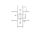
- reference numeral 3 indicates an upper punch
- reference numeral 6 indicates a lower punch
- reference numeral 4 indicates a die.
- the punch and die have a cross-section with a radius r (2 mm as an example).
- the work W which is a powder, has a cylindrical shape filled in a space surrounded by these dies as shown in FIG. If the upper punch 3 is now driven and the lower punch 6 is stationary, the compression load of the upper punch 3 is P D , and the stationary load, which is the reaction force of the lower punch 6, is P S.
- P S P D ⁇ (2 ⁇ rh ⁇ friction coefficient ⁇ internal stress) (1) It is.
- the frictional resistance is in the parenthesis on the right side.
- the extraction force can be measured. Therefore, if the friction coefficient is known, the internal stress can be estimated by the equation (2), so that the extraction force can be considered as an index of internal stress, that is, density uniformity inside the green compact.
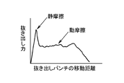
- FIG. 5 is an example of a graph showing the relationship between the punch moving distance and the extraction force during extraction. Up to the last peak value of the proportional portion that rises sharply corresponds to static friction, and the subsequent low portion is dynamic friction, which is about half of static friction.
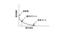
- the relationship between the friction coefficient and the relative speed of the punch is an exponential function.
- it is represented by a semilogarithmic graph, it is a straight line descending to the right, but it is as shown in FIG.
- a value in contact with the vertical axis, that is, a value at a speed of 0 is a static friction coefficient, and a value on the right side corresponds to a dynamic friction coefficient.
- the punching speed is about 10 to 100 mm per second, but in an impact press, it reaches 1 m per second. Therefore, the impact press is a fraction of that of a normal press in terms of friction coefficient.
- FIG. 7 is a graph showing the relationship between the density and the extraction force between normal compression molding performed without generating an impact force by changing the type of powder, and compression molding with an impact force applied, (a) Tungsten carbide (WC) granulated powder, (b) is the case of alumina powder.
- Tungsten carbide is a fine powder of about 10 ⁇ m, but it is too fine to be filled easily, so a binder is mixed to make a size of about 50 ⁇ m. This is called granulated powder.
- the dashed line is normal compression molding, and the solid line is compression molding with impact applied.
- the graph rises to the right.
- the extraction force increases.
- the extraction force decreases by about 25 to 45% by applying an impact, and the density is The higher the value, the greater the effect.
- the impact force is not effective just by adding this.
- a preferable preload value is generally in the range of 4.9 to 14.7 MPa (50 to 150 kg / cm 2 ) although it depends on the size of the mold and the kind of powder. If it is lower than this, there are too many internal voids and even if an impact force is applied, there is no effect, and if it is higher than this, the internal voids are confined, which is not preferable.
- the stroke during compression by impact force is also an important factor.
- the average particle size of the powder such as ceramics is about 50 ⁇ m, but the stroke needs to be at least twice this, that is, 100 ⁇ m or more. Small strokes smaller than this are not different from compression by normal static pressure, and there is no effect of impact force. On the other hand, a larger stroke is preferable.
- the impact force generating means is a magnetostrictive element or a magnetostrictive actuator.
- One is a rod having a length of about 50 mm, and when a coil arranged around it is excited, a deformation of 200 ⁇ m is instantaneously generated. When two of these are used in series, a large stroke of 400 ⁇ m can be easily realized.
- the impact force when effectively acting is 98 MPa (1 ton / cm 2 ) or more.
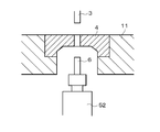
- FIG. 1 is a front view showing the compression molding apparatus of the first embodiment
- FIG. 2 is a sectional view showing the periphery of a mold as the main part
- each reference numeral is the same as that used in FIG.
- 24 denotes a pressure sensor for measuring an extraction force and the like
- 52 denotes a magnetostrictive actuator which is deformed by excitation.
- the pressure sensor 24 may be provided on the lower punch 6 side. In short, it is provided according to the pressure to be measured. I just need it.
- the magnetostrictive actuator 52 is inserted between the lower punch 6 and the lower ram 5, but the magnetostrictive actuator may be inserted on the upper punch 3 side, or may be provided on both the upper and lower sides. Absent.
- the lower punch 6 By rotating the ball screw 51 by a motor (not shown), the lower punch 6 is raised to form a recess with the lower punch 6 at the bottom in the center of the die 4, and in this space formed by the lower punch 6 and the die 4. The powder is filled to the surface height. Subsequently, the upper punch 3 is lowered by rotating the ball screw 21 with another motor (not shown) to compress the powder with static pressure until it reaches a predetermined pressure (the aforementioned “preferred preload”), and then the magnetostrictive actuator 52. Is applied and an impact force is applied once to the powder surrounded by the upper and lower punches 3 and 6.
- a predetermined pressure the aforementioned “preferred preload”
- the impact force is generated by applying a voltage to the magnetostrictive actuator 52 instantaneously.
- a pulse voltage of about 200 ⁇ sec is applied at 300 V and 100 A by a power supply device (not shown).
- the upper punch 3 or the lower punch 6 is moved again and compressed again with static pressure until it reaches a predetermined pressure again, and then the magnetostrictive actuator 52 is operated to apply an impact force. .
- This operation is repeated as many times as necessary, for example 10 to 20 times.
- the spring back of the extracted workpiece W is also 1 ⁇ 2 or less compared to the case of only compression by static pressure.
- Example 2 When the whole is compressed evenly, the volume is reduced to 1/2 of the initial filling in the case of ceramic powder, and to 1/3 in the case of tungsten carbide granulated powder, but the internal voids disappear, Even if a baking treatment is performed in the process, a high-quality intermediate product is obtained that does not cause defects such as cracks and chips due to shrinkage.
- Example 2 When the whole is compressed evenly, the volume is reduced to 1/2 of the initial filling in the case of ceramic powder, and to 1/3 in the case of tungsten carbide granulated powder, but the internal voids disappear, Even if a baking treatment is performed in the process, a high-quality intermediate product is obtained that does not cause defects such as cracks and chips due to shrinkage.
- Example 2 Example 2
- FIG. 8A is a schematic diagram in which this situation is changed from left to right in time series.
- the upper punch 3 is lowered to compress the powder to a predetermined pressure with a static pressure.
- the powder is compressed by impact force generating means provided on the lower punch 6.
- the lower punch 6 returns to the original position in a time of about 1 / 10,000 second, but since the powder is compressed and the volume is reduced, a gap is formed.
- the spring back of the powder gradually progresses later than this, and the gap decreases, but the movement of the powder at this time is static friction against the wall surface, so the resistance is large and it takes time and density. Non-uniformity occurs.
- a gap remains as much as the powder is finally compressed. Therefore, the cycle from the lower punch 6 being lifted up to eliminating this gap is one cycle, after which it returns to the left end state and a second impact force is applied.
- FIG. 9 is a partial cross-sectional view near the lower end of the upper ram drive mechanism for explaining this situation.
- Reference numeral 2 is the upper ram
- reference numeral 21 is a ball screw (the front end portion) for driving the upper ram
- reference numeral 22 is the upper ram 2.
- Reference numeral 3 denotes an upper punch
- reference numeral 31 denotes a punch holder for holding the upper punch 3 on the upper ram 2.
- Such a locking structure is for raising the upper ram 2 by means of the ball screw 21.
- a clearance of the dimension g is provided in the locking portion in the vertical direction.
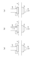
- FIG. 8A is a schematic diagram that is changed from the left to the right in time series as in FIG. 8A.
- the upper punch 3 descends and the powder is compressed to a predetermined pressure with static pressure as in the case of FIG.
- the ball screw 21 is reversely rotated to loosen the lower ram 2 so that the upper ram 2 floats.
- the “floating state” will be described with reference to FIG. 10A shows a standby state before the press enters compression processing, and the upper ram 2 is hung from the tip of the ball screw 21, and there is a gap between the tip of the ball screw 21 and the upper ram 2. Has occurred.
- (B) is a state when the ball screw 21 is actuated to reduce the pressure. The tip of the ball screw 21 is in close contact with the upper ram 2.
- (C) is a state in which the ball screw 21 is reversed to loosen the pressure reduction of the upper ram 2. No force acts between the tip of the ball screw 21 and the upper ram 2, and the upper ram 2 is in a floating state.
- a reaction force from the powder to be compressed acts on the upper punch 3 upward. It is due to this reaction force that the upper ram 2 floats.
- the upper ram 2 when the ball screw 21 is raised by the gap g in FIG. 9, the upper ram 2 is in a floating state, and the upper punch 3 is placed on the powder with the weight of the upper portion. If it is the predetermined pressure and the weight of the upper ram 2 is insufficient for the preferable preload, the weight of the upper ram 2 may be added.
- the gap g provided in the engaging portion with the ball screw 21 corresponds to the gap generated by the impact force, and is preferably about 0.2 mm, for example.
Landscapes
- Engineering & Computer Science (AREA)
- Mechanical Engineering (AREA)
- Physics & Mathematics (AREA)
- Electromagnetism (AREA)
- Press Drives And Press Lines (AREA)
- Press-Shaping Or Shaping Using Conveyers (AREA)
- Powder Metallurgy (AREA)
Abstract
Description
PS = PD-(2πrh×摩擦係数×内部応力)・・・・(1)
である。右辺のかっこ内が摩擦抵抗である。
PE = 2πrh×摩擦係数×内部応力 ・・・・・・・(2)
である。
実施例1
実施例2
Claims (8)
- ダイの上下に上パンチと下パンチをそれぞれ配置し、その上パンチと下パンチとダイとで形成される空間内に粉体を充填し、下パンチを上昇させ、もしくは上パンチを下降させて前記粉体を圧縮かつ成形する縦型の粉体の圧縮成形方法において、
前記下パンチを上昇させ、もしくは前記上パンチを下降させて前記空間に充填された粉体を所定圧力まで圧縮し、
ついで、前記上パンチとその上パンチを取り付けてある上ラムとの間に設けられた衝撃力発生手段、もしくは前記下パンチとその下パンチを取り付けてある下ラムとの間に設けられた衝撃力発生手段を作動させて前記粉体にさらなる圧縮を加えることを特徴とする粉体の圧縮成形方法。 - 前記衝撃力発生手段を作動させて前記粉体にさらなる圧縮を加えた後に、前記下パンチを再度上昇させ、もしくは前記上パンチを再度下降させることにより、前記粉体の嵩の減少により生じた隙間をなくすことを特徴とする請求項1に記載の粉体の圧縮成形方法。
- 前記上パンチを昇降させる昇降機構の内部に前記上パンチが上下方向に自由に落下できる所定寸法の隙間を設けておき、前記下パンチを上昇させ、もしくは前記上パンチを下降させて前記粉体を所定圧力まで圧縮する加工は、前記上パンチの前記自由な落下による上パンチ側の重量で行うことを特徴とする請求項1または2に記載の粉体の圧縮成形方法。
- 前記下パンチを上昇させ、もしくは前記上パンチを下降させることによる前記粉体の所定圧力までの圧縮と、前記衝撃力発生手段によるさらなる圧縮とを繰り返し行うことを特徴とする請求項1または2に記載の粉体の圧縮成形方法。
- 前記衝撃力発生手段は、磁歪アクチュエータを含むことを特徴とする請求項1または2に記載の粉体の圧縮成形方法。
- 前記衝撃力発生手段によるさらなる圧縮のストロークは、前記粉体の平均粒径の2倍以上であることを特徴とする請求項1または2に記載の粉体の圧縮成形方法。
- ダイの上下に上パンチと下パンチとをそれぞれ配置し、前記上パンチと下パンチとダイとで形成される空間内に粉体を充填し、前記下パンチを上昇させ、もしくは上パンチを下降させて前記粉体を圧縮かつ成形する縦型の粉体の圧縮成形装置において、
前記上パンチとその上パンチを取り付けてある上ラムとの間、および前記下パンチとその下パンチを取り付けてある下ラムとの間の少なくともいずれか一方の間に、衝撃力発生手段としての磁歪アクチュエータが設けられていることを特徴とする粉体の圧縮成形装置。 - 前記上パンチを昇降させる昇降機構と、
前記上パンチを自由に落下させることのできるようにその昇降機構の内部に設けられた上下方向の隙間とを更に備え、
前記上パンチにおける、前記隙間より下側の部分の重量が前記粉体を圧縮するための前記所定の圧力として作用するように構成されていることを特徴とする請求項7に記載の粉体の圧縮成形装置。
Priority Applications (3)
| Application Number | Priority Date | Filing Date | Title |
|---|---|---|---|
| EP10794037.1A EP2450179B8 (en) | 2009-07-03 | 2010-06-23 | Compression molding method for powder and device therefor |
| US13/382,061 US8679387B2 (en) | 2009-01-14 | 2010-06-23 | Method and apparatus for compressing particulate matter |
| CN201080029655.1A CN102548745B (zh) | 2009-07-03 | 2010-06-23 | 粉体的压缩成形方法及其装置 |
Applications Claiming Priority (2)
| Application Number | Priority Date | Filing Date | Title |
|---|---|---|---|
| JP2009-158765 | 2009-07-03 | ||
| JP2009158765A JP5481112B2 (ja) | 2009-01-14 | 2009-07-03 | 粉体の圧縮成形方法ならびにその装置 |
Publications (1)
| Publication Number | Publication Date |
|---|---|
| WO2011001868A1 true WO2011001868A1 (ja) | 2011-01-06 |
Family
ID=43411557
Family Applications (1)
| Application Number | Title | Priority Date | Filing Date |
|---|---|---|---|
| PCT/JP2010/060618 Ceased WO2011001868A1 (ja) | 2009-01-14 | 2010-06-23 | 粉体の圧縮成形方法ならびにその装置 |
Country Status (3)
| Country | Link |
|---|---|
| EP (1) | EP2450179B8 (ja) |
| CN (1) | CN102548745B (ja) |
| WO (1) | WO2011001868A1 (ja) |
Cited By (1)
| Publication number | Priority date | Publication date | Assignee | Title |
|---|---|---|---|---|
| CN115464916A (zh) * | 2022-10-24 | 2022-12-13 | 四川通冠机械设备有限公司 | 一种环形碳素制品成型设备 |
Families Citing this family (4)
| Publication number | Priority date | Publication date | Assignee | Title |
|---|---|---|---|---|
| CN106003376B (zh) * | 2016-07-14 | 2019-01-29 | 吴江佳亿电子科技有限公司 | 一种能防止模具损坏的高压陶瓷电容器瓷介质芯片冲压机 |
| CN106003377A (zh) * | 2016-07-14 | 2016-10-12 | 吴江佳亿电子科技有限公司 | 一种能防止缺料的高压陶瓷电容器瓷介质芯片成型压机 |
| CN107696378B (zh) * | 2017-11-23 | 2023-06-06 | 华南理工大学 | 一种超高分子量聚合物异型制件成型方法及设备 |
| CN112046072A (zh) * | 2020-08-27 | 2020-12-08 | 广东达诚技术股份有限公司 | 成型机的模台高度位置自动检测调节装置 |
Citations (4)
| Publication number | Priority date | Publication date | Assignee | Title |
|---|---|---|---|---|
| US3613166A (en) * | 1969-06-26 | 1971-10-19 | Dresser Ind | Compaction of particulate matter |
| JPH0957496A (ja) * | 1995-08-22 | 1997-03-04 | Arutekusu:Kk | 超音波粉末加圧成形装置 |
| JP2000197996A (ja) * | 1998-11-02 | 2000-07-18 | Sumitomo Special Metals Co Ltd | 成形方法及び成形装置 |
| JP2004174596A (ja) | 2002-11-29 | 2004-06-24 | Nano Control:Kk | 粉末プレス装置および粉末プレス方法 |
Family Cites Families (9)
| Publication number | Priority date | Publication date | Assignee | Title |
|---|---|---|---|---|
| US3612166A (en) * | 1969-09-08 | 1971-10-12 | Diebold Inc | Burning bar attack resistant device for vault doors |
| DE3919847A1 (de) * | 1989-06-15 | 1990-12-20 | Mannesmann Ag | Verfahren und vorrichtung zur herstellung masshaltiger presslinge |
| CN1263497A (zh) * | 1998-04-08 | 2000-08-16 | 米拉克龙公司 | 形成压制品的冲压方法和设备 |
| US6325965B1 (en) * | 1998-11-02 | 2001-12-04 | Sumitomo Special Metals Co., Ltd. | Forming method and forming apparatus |
| US6698267B1 (en) * | 2000-04-28 | 2004-03-02 | Morphic Technologies Aktiebolag | Method and impact machine for forming a body |
| SE525853C2 (sv) * | 2003-09-25 | 2005-05-17 | Hydropulsor Ab | Förfarande och anordning för formning av pulverformigt material |
| JP2005095958A (ja) * | 2003-09-26 | 2005-04-14 | Takashima Sangyo Kk | プレス機 |
| JP2007030063A (ja) * | 2005-07-25 | 2007-02-08 | Meiwa E Tec:Kk | 圧入装置 |
| JP5534996B2 (ja) * | 2010-08-02 | 2014-07-02 | 三和システムエンジニアリング株式会社 | 粉体の圧縮成形装置およびその衝撃力遮断機構 |
-
2010
- 2010-06-23 WO PCT/JP2010/060618 patent/WO2011001868A1/ja not_active Ceased
- 2010-06-23 EP EP10794037.1A patent/EP2450179B8/en not_active Not-in-force
- 2010-06-23 CN CN201080029655.1A patent/CN102548745B/zh not_active Expired - Fee Related
Patent Citations (4)
| Publication number | Priority date | Publication date | Assignee | Title |
|---|---|---|---|---|
| US3613166A (en) * | 1969-06-26 | 1971-10-19 | Dresser Ind | Compaction of particulate matter |
| JPH0957496A (ja) * | 1995-08-22 | 1997-03-04 | Arutekusu:Kk | 超音波粉末加圧成形装置 |
| JP2000197996A (ja) * | 1998-11-02 | 2000-07-18 | Sumitomo Special Metals Co Ltd | 成形方法及び成形装置 |
| JP2004174596A (ja) | 2002-11-29 | 2004-06-24 | Nano Control:Kk | 粉末プレス装置および粉末プレス方法 |
Non-Patent Citations (1)
| Title |
|---|
| See also references of EP2450179A4 * |
Cited By (2)
| Publication number | Priority date | Publication date | Assignee | Title |
|---|---|---|---|---|
| CN115464916A (zh) * | 2022-10-24 | 2022-12-13 | 四川通冠机械设备有限公司 | 一种环形碳素制品成型设备 |
| CN115464916B (zh) * | 2022-10-24 | 2023-11-17 | 黄骅市晶鑫重型锻压有限公司 | 一种环形碳素制品成型设备 |
Also Published As
| Publication number | Publication date |
|---|---|
| EP2450179B8 (en) | 2016-10-12 |
| EP2450179B1 (en) | 2016-08-31 |
| EP2450179A1 (en) | 2012-05-09 |
| EP2450179A4 (en) | 2013-11-06 |
| CN102548745B (zh) | 2014-12-10 |
| CN102548745A (zh) | 2012-07-04 |
Similar Documents
| Publication | Publication Date | Title |
|---|---|---|
| WO2011001868A1 (ja) | 粉体の圧縮成形方法ならびにその装置 | |
| JP2010214381A (ja) | 段付カップ状部品の成形装置及び成形方法 | |
| JP2002514270A (ja) | コンパクトを成形するための衝撃方法及び機械 | |
| WO2016199889A1 (ja) | 金属切削屑圧縮機 | |
| JP5481112B2 (ja) | 粉体の圧縮成形方法ならびにその装置 | |
| EP1541327A1 (en) | Powder compacting method and powder compacting system | |
| CN111421038B (zh) | 一种冲压模组及其工作方法 | |
| CN120079864B (zh) | 一种带内沉槽的粉末冶金坯件的高精密连续压制成型装置及方法 | |
| CN101758633A (zh) | 一种粉末成型机非同时加压机构 | |
| JP2012245562A (ja) | 粉末成形装置 | |
| RU2381870C2 (ru) | Способ прессования штабиков из порошков тугоплавких металлов и пресс-форма для их прессования | |
| JP5590378B2 (ja) | 粉末成形装置およびそれを用いた粉末成形方法 | |
| JP2765766B2 (ja) | 段付き形状圧粉体の成形方法、およびその成形装置 | |
| JP2838477B2 (ja) | 段付成形品の粉末成形方法および装置 | |
| RU2373025C1 (ru) | Устройство для прессования заготовок из порошков тугоплавких металлов | |
| US6167802B1 (en) | Sliding frame press | |
| JP2004291046A (ja) | 粉末成形における成形体のクラック防止方法及び装置 | |
| JP3926556B2 (ja) | 粉末成形装置 | |
| JP5462957B1 (ja) | 長尺軽金属ビレット及びその製造方法 | |
| JP2006187793A (ja) | 粉末成形装置 | |
| CN114559037A (zh) | 一种粉末冶金压制模 | |
| JPH0716795A (ja) | 粉末成形プレス | |
| JPH04147798A (ja) | 粉末成形プレスにおける成形品のクラック除去方法および装置 | |
| JP5136191B2 (ja) | 粉末成形機及びその作動方法 | |
| JPH06198497A (ja) | 粉末成形プレスの加圧制御方法および装置 |
Legal Events
| Date | Code | Title | Description |
|---|---|---|---|
| WWE | Wipo information: entry into national phase |
Ref document number: 201080029655.1 Country of ref document: CN |
|
| 121 | Ep: the epo has been informed by wipo that ep was designated in this application |
Ref document number: 10794037 Country of ref document: EP Kind code of ref document: A1 |
|
| REEP | Request for entry into the european phase |
Ref document number: 2010794037 Country of ref document: EP |
|
| WWE | Wipo information: entry into national phase |
Ref document number: 2010794037 Country of ref document: EP |
|
| NENP | Non-entry into the national phase |
Ref country code: DE |
|
| WWE | Wipo information: entry into national phase |
Ref document number: 13382061 Country of ref document: US |