WO2011001977A1 - 内燃機関燃料噴射ノズル、ノズル素材およびその製造方法 - Google Patents
内燃機関燃料噴射ノズル、ノズル素材およびその製造方法 Download PDFInfo
- Publication number
- WO2011001977A1 WO2011001977A1 PCT/JP2010/061054 JP2010061054W WO2011001977A1 WO 2011001977 A1 WO2011001977 A1 WO 2011001977A1 JP 2010061054 W JP2010061054 W JP 2010061054W WO 2011001977 A1 WO2011001977 A1 WO 2011001977A1
- Authority
- WO
- WIPO (PCT)
- Prior art keywords
- nozzle
- surface side
- tip outer
- internal combustion
- combustion engine
- Prior art date
- Legal status (The legal status is an assumption and is not a legal conclusion. Google has not performed a legal analysis and makes no representation as to the accuracy of the status listed.)
- Ceased
Links
Images


Classifications
-
- F—MECHANICAL ENGINEERING; LIGHTING; HEATING; WEAPONS; BLASTING
- F02—COMBUSTION ENGINES; HOT-GAS OR COMBUSTION-PRODUCT ENGINE PLANTS
- F02M—SUPPLYING COMBUSTION ENGINES IN GENERAL WITH COMBUSTIBLE MIXTURES OR CONSTITUENTS THEREOF
- F02M61/00—Fuel-injectors not provided for in groups F02M39/00 - F02M57/00 or F02M67/00
- F02M61/16—Details not provided for in, or of interest apart from, the apparatus of groups F02M61/02 - F02M61/14
- F02M61/168—Assembling; Disassembling; Manufacturing; Adjusting
-
- F—MECHANICAL ENGINEERING; LIGHTING; HEATING; WEAPONS; BLASTING
- F02—COMBUSTION ENGINES; HOT-GAS OR COMBUSTION-PRODUCT ENGINE PLANTS
- F02M—SUPPLYING COMBUSTION ENGINES IN GENERAL WITH COMBUSTIBLE MIXTURES OR CONSTITUENTS THEREOF
- F02M61/00—Fuel-injectors not provided for in groups F02M39/00 - F02M57/00 or F02M67/00
- F02M61/16—Details not provided for in, or of interest apart from, the apparatus of groups F02M61/02 - F02M61/14
- F02M61/18—Injection nozzles, e.g. having valve seats; Details of valve member seated ends, not otherwise provided for
-
- B—PERFORMING OPERATIONS; TRANSPORTING
- B22—CASTING; POWDER METALLURGY
- B22F—WORKING METALLIC POWDER; MANUFACTURE OF ARTICLES FROM METALLIC POWDER; MAKING METALLIC POWDER; APPARATUS OR DEVICES SPECIALLY ADAPTED FOR METALLIC POWDER
- B22F3/00—Manufacture of workpieces or articles from metallic powder characterised by the manner of compacting or sintering; Apparatus specially adapted therefor ; Presses and furnaces
- B22F3/02—Compacting only
-
- B—PERFORMING OPERATIONS; TRANSPORTING
- B22—CASTING; POWDER METALLURGY
- B22F—WORKING METALLIC POWDER; MANUFACTURE OF ARTICLES FROM METALLIC POWDER; MAKING METALLIC POWDER; APPARATUS OR DEVICES SPECIALLY ADAPTED FOR METALLIC POWDER
- B22F3/00—Manufacture of workpieces or articles from metallic powder characterised by the manner of compacting or sintering; Apparatus specially adapted therefor ; Presses and furnaces
- B22F3/12—Both compacting and sintering
- B22F3/14—Both compacting and sintering simultaneously
- B22F3/15—Hot isostatic pressing
-
- B—PERFORMING OPERATIONS; TRANSPORTING
- B22—CASTING; POWDER METALLURGY
- B22F—WORKING METALLIC POWDER; MANUFACTURE OF ARTICLES FROM METALLIC POWDER; MAKING METALLIC POWDER; APPARATUS OR DEVICES SPECIALLY ADAPTED FOR METALLIC POWDER
- B22F7/00—Manufacture of composite layers, workpieces, or articles, comprising metallic powder, by sintering the powder, with or without compacting wherein at least one part is obtained by sintering or compression
- B22F7/06—Manufacture of composite layers, workpieces, or articles, comprising metallic powder, by sintering the powder, with or without compacting wherein at least one part is obtained by sintering or compression of composite workpieces or articles from parts, e.g. to form tipped tools
- B22F7/062—Manufacture of composite layers, workpieces, or articles, comprising metallic powder, by sintering the powder, with or without compacting wherein at least one part is obtained by sintering or compression of composite workpieces or articles from parts, e.g. to form tipped tools involving the connection or repairing of preformed parts
-
- C—CHEMISTRY; METALLURGY
- C22—METALLURGY; FERROUS OR NON-FERROUS ALLOYS; TREATMENT OF ALLOYS OR NON-FERROUS METALS
- C22C—ALLOYS
- C22C19/00—Alloys based on nickel or cobalt
- C22C19/03—Alloys based on nickel or cobalt based on nickel
- C22C19/05—Alloys based on nickel or cobalt based on nickel with chromium
- C22C19/051—Alloys based on nickel or cobalt based on nickel with chromium and Mo or W
- C22C19/055—Alloys based on nickel or cobalt based on nickel with chromium and Mo or W with the maximum Cr content being at least 20% but less than 30%
-
- C—CHEMISTRY; METALLURGY
- C22—METALLURGY; FERROUS OR NON-FERROUS ALLOYS; TREATMENT OF ALLOYS OR NON-FERROUS METALS
- C22C—ALLOYS
- C22C38/00—Ferrous alloys, e.g. steel alloys
- C22C38/04—Ferrous alloys, e.g. steel alloys containing manganese
-
- C—CHEMISTRY; METALLURGY
- C22—METALLURGY; FERROUS OR NON-FERROUS ALLOYS; TREATMENT OF ALLOYS OR NON-FERROUS METALS
- C22C—ALLOYS
- C22C38/00—Ferrous alloys, e.g. steel alloys
- C22C38/18—Ferrous alloys, e.g. steel alloys containing chromium
- C22C38/22—Ferrous alloys, e.g. steel alloys containing chromium with molybdenum or tungsten
-
- C—CHEMISTRY; METALLURGY
- C22—METALLURGY; FERROUS OR NON-FERROUS ALLOYS; TREATMENT OF ALLOYS OR NON-FERROUS METALS
- C22C—ALLOYS
- C22C38/00—Ferrous alloys, e.g. steel alloys
- C22C38/18—Ferrous alloys, e.g. steel alloys containing chromium
- C22C38/24—Ferrous alloys, e.g. steel alloys containing chromium with vanadium
-
- C—CHEMISTRY; METALLURGY
- C22—METALLURGY; FERROUS OR NON-FERROUS ALLOYS; TREATMENT OF ALLOYS OR NON-FERROUS METALS
- C22C—ALLOYS
- C22C38/00—Ferrous alloys, e.g. steel alloys
- C22C38/18—Ferrous alloys, e.g. steel alloys containing chromium
- C22C38/34—Ferrous alloys, e.g. steel alloys containing chromium with more than 1.5% by weight of silicon
-
- F—MECHANICAL ENGINEERING; LIGHTING; HEATING; WEAPONS; BLASTING
- F02—COMBUSTION ENGINES; HOT-GAS OR COMBUSTION-PRODUCT ENGINE PLANTS
- F02M—SUPPLYING COMBUSTION ENGINES IN GENERAL WITH COMBUSTIBLE MIXTURES OR CONSTITUENTS THEREOF
- F02M61/00—Fuel-injectors not provided for in groups F02M39/00 - F02M57/00 or F02M67/00
- F02M61/16—Details not provided for in, or of interest apart from, the apparatus of groups F02M61/02 - F02M61/14
-
- B—PERFORMING OPERATIONS; TRANSPORTING
- B22—CASTING; POWDER METALLURGY
- B22F—WORKING METALLIC POWDER; MANUFACTURE OF ARTICLES FROM METALLIC POWDER; MAKING METALLIC POWDER; APPARATUS OR DEVICES SPECIALLY ADAPTED FOR METALLIC POWDER
- B22F2998/00—Supplementary information concerning processes or compositions relating to powder metallurgy
- B22F2998/10—Processes characterised by the sequence of their steps
-
- F—MECHANICAL ENGINEERING; LIGHTING; HEATING; WEAPONS; BLASTING
- F02—COMBUSTION ENGINES; HOT-GAS OR COMBUSTION-PRODUCT ENGINE PLANTS
- F02M—SUPPLYING COMBUSTION ENGINES IN GENERAL WITH COMBUSTIBLE MIXTURES OR CONSTITUENTS THEREOF
- F02M2200/00—Details of fuel-injection apparatus, not otherwise provided for
- F02M2200/80—Fuel injection apparatus manufacture, repair or assembly
- F02M2200/8046—Fuel injection apparatus manufacture, repair or assembly the manufacture involving injection moulding, e.g. of plastic or metal
Definitions
- the present invention relates to a fuel injection nozzle for an internal combustion engine, and more particularly to a fuel injection nozzle, a nozzle material, and a method for manufacturing the same that are suitable for use in a diesel engine of an internal combustion engine and have excellent durability.
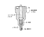
- a fuel injection nozzle 1 arranged in a combustion chamber of an internal combustion engine for ships or the like has an injection port 2a at one end and an injection port 2a at the other end, as shown in the sectional view of FIG.
- the fuel supplied from the fuel passage 1a (not shown) can be injected from the injection port 2a at a predetermined timing.
- the nozzle head (nozzle) 2 is manufactured using, for example, high-speed tool steel SKH51.
- Patent Document 1 proposes a fuel injection nozzle for a diesel engine that can improve the life of a nozzle tip (nozzle).
- the nozzle tip (nozzle) is made of a high Ni—Cr—Al alloy, and the nozzle tip (nozzle) and the valve seat are separated, and the valve seat material is the nozzle.
- the material is harder than the material of the tip (nozzle) (see FIGS. 1 and 2).
- the tip portion and the base end portion of the nozzle tip (nozzle) are further separated, and the tip portion exposed in the combustion chamber is made of a high Ni—Cr—Al alloy.
- the base end portion covered with the mounting cap is preferably made of a material having a hardness higher than that of the nozzle tip (nozzle), and the two are preferably metallurgically joined together. According to the technique described in Patent Document 1, the life of the nozzle tip (nozzle) can be significantly extended.
- Patent Document 2 proposes a nozzle head (nozzle) for an injection nozzle made of mechanically alloyed chromium / nickel steel alloyed with C, Al, Ti, Fe, N, O and yttrium oxide. .
- the nozzle head (nozzle) according to the technique described in Patent Document 2 is more erosive than the conventional nozzle head (nozzle) even in an erosive, chemical and thermal environment in a combustion chamber of an internal combustion engine such as a diesel engine.
- the service life is about twice as long.
- Patent Document 2 has a description that when a nozzle head (nozzle) for an injection nozzle is manufactured from an alloy named “Inconel Alloy MA758” (trade name), the service life is doubled or tripled.
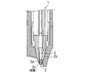
- Patent Document 5 describes a fuel injection nozzle of the type shown in FIG.
- the fuel injection nozzle 1 described in Patent Document 5 includes a single base body (center member) 2b and a nozzle head (nozzle) 2 having a lower end thereof covered with a coating (outer coating) 2c.
- a longitudinal axial hole having an upper region, a pressure chamber for hydraulic operation of a nozzle needle (needle valve) 3 disposed in the lower region, and a lower region disposed in the lower region.
- the coating (outer coating) 2c is formed of a high temperature corrosion resistant alloy. Laser bonding, plasma spraying, welding or powder metallurgy are suitable for bonding the high-temperature corrosion resistant alloy coating to the substrate.
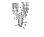
- Patent Document 3 describes a nozzle of the type shown in FIG.
- the nozzle 2 described in Patent Document 3 surrounds a central member 2b having a central longitudinal channel communicating with a number of nozzle holes (injection ports 2a) and having a lower portion, and a lower portion of the central member. This is a nozzle formed by brazing the central member 2b and the outer cover 2c to each other.
- the outer cover 2c is made of a corrosion-resistant alloy
- the center member 2b is made of an iron-based alloy having a fatigue strength of ⁇ 500 MPa.
- the needle valve 3 carries a ring-shaped blocking member 3a for quickly closing the injection hole 2a at the end of injection.
- the technique described in Patent Document 3 has a problem that the brazing process is complicated and productivity is lowered.
- Patent Document 4 describes a diesel engine fuel valve nozzle of the type shown in FIG.
- the outer region (outer coating) 2c is made of a first material made of a corrosion-resistant first alloy
- the other region (center member) 2b other than the outer region is made of a second alloy.
- a boundary region therebetween is made of a material having a solidified (integrated) structure in which no microcracks exist.
- the first alloy is an alloy having corrosion resistance and the second alloy is preferably an alloy having higher fatigue strength than the first alloy.
- Patent Document 4 discloses a method using powder metallurgy as shown in FIG. 4, for example, as an example of a method for manufacturing a nozzle having a tip portion having a two-layer structure of different materials.
- a core member (core material) 10 that forms a region other than the outer region of the nozzle (the outer surface side of the nozzle tip) is preliminarily formed in a predetermined shape (the inner surface of the nozzle 2 as a finished product) with a molten material made of the second alloy. The shape is similar to the side material 22).
- the molded core member (core material) 10 is inserted into a mold (container) 100.
- the mold 100 is constructed from a bottom wall 14, a side wall 15, a cover 16, and a filling nozzle 17.
- the powder of the first alloy constituting the outer region of the nozzle is filled into the mold (container) 100 through the filling nozzle 17 and the cavity around the core member (core material) 10 Fill the part. Then, if necessary, the mold is sucked and closed so as to be airtight. Thereafter, the mold 100 is heated to a predetermined temperature, subjected to hot isostatic pressing (HIP treatment) and sintered to be solidified with a dense body having no holes, and the tip is made of a dissimilar material. It becomes a nozzle material having a layer structure. This material is machined to obtain a nozzle 2 (finished product) having a desired shape.
- HIP treatment hot isostatic pressing
- the present invention solves such problems of the prior art, and can be applied to at least a fuel injection nozzle of the type shown in FIGS. 6 to 8, has a simple manufacturing process, is highly productive, and
- An object of the present invention is to provide an internal combustion engine fuel injection nozzle, a nozzle material, and a manufacturing method thereof that are inexpensive and can be manufactured with high accuracy.
- the nozzle targeted by the present invention is for a fuel injection nozzle of an internal combustion engine, particularly a diesel engine.
- the diesel engine may be a four-stroke crosshead engine, but is preferably a two-stroke crosshead engine. This engine often operates on heavy fuel oil that may even contain sulfur. For this reason, the nozzle used in this engine is strictly required to have a long life.
- the present inventors have conceived the application of a metal powder injection molding method (MIM method). Then, the nozzle main body 22 constituting the nozzle by applying the MIM method, and the nozzle main body 22 made of a different material, and the nozzle front end outer surface side material 21 covering the front end outer surface side of the nozzle main body are separately provided.
- MIM method metal powder injection molding method
- Nozzle material for an internal combustion engine fuel injection nozzle made of a material different from the nozzle body and comprising a nozzle tip outer surface side material disposed so as to cover the tip outer surface side of the nozzle body
- the nozzle body is formed by a metal powder injection molding method
- the nozzle tip outer surface side material is formed by a metal powder injection molding method separately from the nozzle body
- the nozzle A nozzle material for a fuel injection nozzle of an internal combustion engine wherein a main body and an outer surface side material of the nozzle tip are overlapped and joined together.
- the nozzle body is made of hot tool alloy tool steel or high speed tool steel, and the nozzle tip outer surface side material is made of a Ni-base superalloy.
- Nozzle material for internal combustion engine fuel injection nozzles is made of a Ni-base superalloy.
- Nozzle material for internal combustion engine fuel injection nozzles is made of a Ni-base superalloy.
- Nozzle material for an internal combustion engine fuel injection nozzle made of a material different from the nozzle body and comprising a nozzle tip outer surface side material disposed so as to cover the tip outer surface side of the nozzle body
- the nozzle body is molded into a predetermined shape by a metal powder injection molding method to form a nozzle body molded body, and then the nozzle body molded body is subjected to a degreasing step to obtain a nozzle body degreased body.
- the nozzle tip outer surface side material is molded into a predetermined shape by a metal powder injection molding method to form a nozzle tip outer surface side material molded body, and then the nozzle tip outer surface side material molded body is subjected to a degreasing step, and the nozzle tip outer surface side material After the degreased body, the nozzle tip outer surface side material degreased body is disposed so as to cover the tip outer surface side of the nozzle body degreased body, and then diffusion sintered, and the nozzle tip outer surface Side material degreased body and Serial nozzle body and a brown body integrally joined, method of manufacturing a nozzle material for internal combustion engine fuel injection nozzles, characterized in that the internal combustion engine fuel injection nozzle for nozzle materials.
- the bonding coating agent is a paste obtained by diluting a metal powder that is the same as the metal powder constituting the nozzle body or the nozzle tip outer surface side material and a water-soluble pasty substance with water.
- the manufacturing method of the nozzle raw material for internal combustion engine fuel injection nozzles characterized by the above-mentioned.
- the nozzle body is made of hot tool alloy tool steel or high speed tool steel, and the nozzle tip outer surface side material is made of a Ni-base superalloy. A method for manufacturing a nozzle material for an internal combustion engine fuel injection nozzle.
- a molded body of different materials is separately molded into a near net shape close to the shape of the finished product (product) by the MIM method, and then overlapped and joined to be integrated, so that subsequent machining
- the process can be shortened, the productivity can be increased, and the fuel injection nozzle having the two-layer structure of different materials, which is excellent in dimensional accuracy, can be manufactured at a low cost.
- the nozzle material 20 for an internal combustion engine fuel injection nozzle of the present invention used for the internal combustion engine fuel injection nozzle includes a nozzle body 22 and a nozzle body 22 so as to cover the outer surface side of the tip end portion of the nozzle body 22. It has a structure in which a front end outer surface side member 21 is disposed.
- the nozzle tip portion exhibits a metallurgically joined state at the interface between the nozzle body 22 and the nozzle tip portion outer surface side material 21. Since the tip of the nozzle 2 is arranged so as to be exposed to the combustion chamber of the internal combustion engine, it is exposed to erosive, chemical and thermal loads in the combustion chamber.
- the tip of the nozzle material 20 is covered with a nozzle tip outer surface side material 21 made of a material having excellent heat resistance, corrosion resistance, and erosion resistance different from that of the nozzle body 22.
- materials excellent in heat resistance, corrosion resistance, and erosion resistance include Ni-base superalloys, Co-base superalloys, Fe-base superalloys, etc., and Ni-base superalloys include Inconel 625 alloy, Inconel 686 alloy, etc.
- Examples of the Co-base superalloy include S-816 alloy, and examples of the Fe-base superalloy include Inconel 800 alloy.
- Inconel 625 alloy C: 0.1% or less, Si: 0.5% or less, Mn: 0.5% or less, Cr: 20.0-23.0%, Mo: 8.0-10.0%, Nb: 3.15-4.15% Fe: 5% or less, preferably a composition comprising the balance Ni and inevitable impurities. Furthermore, Ti: 0.4% or less, Al: 0.4% or less may be included. In the case of using the MIM method, it is preferable that Ti and Al are not added and are inevitable impurities. As unavoidable impurities, Ti is allowed to be 0.15% or less, and Al is allowed to be 0.1% or less.
- the nozzle body 22 is preferably made of a material having excellent wear resistance because the needle valve slides on the inner surface side or repeatedly seats on the valve seat.
- materials with excellent wear resistance include alloy tool steels for hot dies specified in JIS G 4404-2006 such as SKD61, high-speed tool steels specified in JIS G 4403-2006 such as SKH51, Examples include alloys such as trivalloy and stellite.
- FIG. 1 In order to increase the bonding area between the nozzle body 22 and the nozzle tip outer surface side material 21 and improve the bonding strength, the shape of the joint between the nozzle body 22 and the nozzle tip outer surface side material 21 is shown in FIG. Various shapes shown in FIG.
- the nozzle material 20 shown in FIG. 1 has the joint shape shown in FIG. 3A. However, from the viewpoint of increasing the joint area, it is preferable to use FIGS. 3B to 3D.
- the joint portion shape shown in FIG. 3 (e) is conceivable, but with this joint portion shape, processing becomes easy, but the joint area decreases, More preferably, the shape is as shown in FIG.
- the nozzle material 20 according to the present invention is formed by combining the nozzle body 22 and the nozzle tip outer surface side material 21 which are formed into a near net shape separately by metal powder injection molding, and joined by diffusion sintering. And integrated. Needless to say, the interface between the nozzle body 22 and the nozzle tip outer surface side member 21 is firmly metallurgically bonded. Next, a preferred method for producing the nozzle material of the present invention will be described.
- the nozzle body 22 or the nozzle tip outer surface side material 21 is respectively molded into a predetermined shape (cross-sectional view) as shown in FIG. 2 by a metal powder injection molding method, and the nozzle body molded body (A) or nozzle tip It is set as the outside member molded body (B).
- a metal powder injection molding method to be used any conventional metal powder injection molding method (MIM) can be applied.
- the metal powder injection molding method is obtained through a kneading step in which metal powder, or an alloy powder such as carbon powder, and a binder are heated, pressurized and mixed, and a pulverizing step in which the cooled and solidified kneaded material is pulverized.
- the plasticized kneaded material is injection-molded in a mold processed into a predetermined shape by an injection molding machine, and cooled and solidified to obtain a metal powder injection molded body having a predetermined shape.
- any metal powder produced by the water atomization method or the gas atomization method is suitable, and the nozzle body is an alloy for hot molds such as SKD61 defined in JIS G4404-2006.
- a powder of an Fe-based superalloy such as a Ni-based superalloy or a Co-based superalloy, having excellent heat resistance, corrosion resistance, and erosion resistance.
- carbonyl powders of iron and Ni may be used to achieve the desired material composition.
- any of ordinary binders for metal powder injection molding can be applied, but a binder in which a wax component, a plastics component and a vegetable oil are further blended is preferable.
- the wax component is a component that is mainly extracted during the degreasing treatment, and it is not necessary to limit the type of the wax component, but examples of preferred wax components include paraffin wax and microcrystalline wax.
- plastic component to be blended examples include thermoplastic resins such as polypropylene, polyethylene, atactic polypropylene, and ethylene-vinyl acetate copolymer (EVA).
- polypropylene or polyethylene is preferable for moldability and production. It is preferable from the viewpoint of cost.
- the vegetable oil is preferably a non-drying vegetable oil. Examples of non-drying vegetable oils include peanut oil, castor oil, olive oil, and salad oil, and preferably one or more selected from them.
- the obtained nozzle body molded body or nozzle tip outer surface side material molded body is subjected to a degreasing step to obtain a nozzle body degreased body or nozzle tip outer surface side material degreased body.
- the degreasing step that can be suitably used in the present invention may be either a solvent degreasing treatment or a heat degreasing treatment.
- solvent degreasing process it is preferable to remove a part of binder by solvent degreasing process, and also to remove the remainder by degreasing sintering process which served as the sintering process.
- the degreasing step may be supercritical carbon dioxide degreasing instead of solvent degreasing and heat degreasing.
- the nozzle tip outer surface side material degreased body subjected to the degreasing process is subjected to the same degreasing process to remove the foreign matter etc.
- the main body degreased body is superposed and disposed so as to cover the outer surface side of the front end portion, and the superposed body (C) is then joined by diffusion sintering.
- the nozzle tip part outer surface side material degreased body and the nozzle body degreased body can be joined and integrated.
- the diffusion sintering temperature is preferably in the range of 1150 to 1400 ° C. If the diffusion sintering temperature is less than 1150 ° C., the desired diffusion sintering does not proceed, and the desired bonding strength at the interface cannot be ensured. On the other hand, at temperatures exceeding 1400 ° C., the crystal grains become coarse and the mechanical properties deteriorate. More preferably, the temperature is 1150 to 1300 ° C.
- the atmosphere for diffusion sintering is preferably a vacuum atmosphere, or a reduced pressure atmosphere using an inert gas such as argon, nitrogen, or the like.
- a bonding coating agent may be applied to the bonding interface.
- the bonding coating agent it is preferable to use a paste-like coating solution obtained by diluting a metal powder that is the same as the metal powder constituting the nozzle body or the nozzle tip outer surface side material and a water-soluble pasty substance with water.
- the water-soluble paste-like substance refers to a substance that dissolves in water and exhibits a paste-like substance, and refers to a paste-like substance that is made from the starch of cereals.
- cereals include wheat, rice, beans, potato, tapioca and the like.
- starchy paste-like substance there is no problem even if a commercially available starch paste is used.
- water-soluble pasty substances other than starchy pasty substances include PVA.
- the paste-like coating solution is preferably blended with 65 to 90% by mass of metal powder and the remaining 5 to 34% by mass of water and starchy paste.
- the superposed body (C) is subjected to diffusion sintering, and is joined and integrated into a combined body.
- HIP treatment hot isostatic pressing
- the interface becomes more strongly bonded, and the sintered density is improved to almost 100% of the true density.
- the HIP treatment is preferably carried out in an argon or nitrogen atmosphere at a treatment temperature of 1000 to 1300 ° C.
- bonded body which performed HIP processing may cool (furnace cooling) the conjugate
- it may cool without furnace cooling, and may perform annealing processing in another process after that.
- the nozzle material 20 integrated in this way is then subjected to finish processing to become the nozzle 2 having a desired product size and shape.
- the finishing process is mainly a machining process such as a cutting process, but since it is formed into a near net shape by a metal powder injection molding method, the processing amount is small.
- the nozzle tip outer surface is applied to the nozzle body using a two-color molding method of metal powder injection molding method. It can also be produced by joining and integrating materials.
- the obtained nozzle material 20 is provided with injection holes 2a and center holes of a predetermined size and shape at predetermined positions corresponding to the fuel injection nozzles of the respective types shown in FIGS. 6 to 8, for example, by machining such as cutting. It is preferable to finish the nozzle 2.
- injection holes 2a and center holes of a predetermined size and shape at predetermined positions corresponding to the fuel injection nozzles of the respective types shown in FIGS. 6 to 8, for example, by machining such as cutting. It is preferable to finish the nozzle 2.
- the raw material powder having an average particle size of 5 to 15 ⁇ m was used.
- One type of raw material powder was SKD61 steel powder for the nozzle body.
- Other raw material powders were Ni-base superalloy powders and used for the nozzle tip outer surface side material.
- the composition of SKD61 steel was 0.35% C-0.97% Si-0.40% Mn-4.93% Cr-1.21% Mo-1.01% V-bal.Fe in mass%.
- the composition of the Ni-base superalloy was 0.02% C-0.18% Si-0.23% Mn-21.8% Cr-8.9% Mo-3.9% Nb-2.4% Fe-bal.Ni in mass%.
- the raw material powder was mixed with a binder so as to be 40% by volume, and kneaded at a temperature of 120 to 180 ° C. to obtain a kneaded product for injection molding.
- a binder a wax component (PW), a plastic component (PE), and a vegetable oil component (peanut oil) were mixed, heated and stirred.
- the blending amount was 35:40:25 in the ratio of wax component: plastic component: vegetable oil component.
- These kneaded materials are cooled and solidified, then pulverized, put into an injection molding machine, cylinder temperature: 110 to 180 ° C., plasticized, and injected into a predetermined mold at a predetermined pressure (100 MPa).
- the nozzle body molded body (A) and the nozzle tip outer surface side molded body (B) having the shapes shown in the drawings were used.
- the degreasing process by a solvent degreasing process was performed, and each degreased body was obtained.
- the degreasing conditions were temperature: 30 ° C. and the solvent was methylene chloride.
- the obtained nozzle body degreased body (A) and the nozzle tip outer surface side material degreased body (B) were superposed to obtain a superposed body (C) as shown in FIG.
- the superposed body (C) was heated in a reduced-pressure nitrogen atmosphere (heating temperature: 1250 ° C.) and diffusion-sintered (sintering time: 2 h) at that temperature to be integrated into a combined body.
- HIP treatment was further performed on a part of it.
- the conditions for the HIP treatment were 1200 ° C. in an argon atmosphere and a pressure of 117 MPa.
- a bonding coating agent was applied to the interface when the layers were overlapped.
- the resulting bonded body was machined to obtain a product with a predetermined size.
- nozzles having the same dimensions were produced by the conventional method shown in FIG.
- the obtained bonded body (nozzle) was subjected to observation of the interface bonding state, tensile test, and fatigue test.
- the test method was as follows. (1) Observation of bonding state of interface About the obtained bonded body, the axial cross section of the bonded body was observed using an optical microscope (magnification: 200 times), and the bonded state of the bonded interface was evaluated.
- Bonding at the interface is indicated by ⁇ when the gap is observed at 2% or more of the total length of the observed bonding interface, ⁇ when the gap is less than 2% to 0.5% or more, and ⁇ when the gap is less than 0.5%.
- the condition was evaluated.
- (2) Tensile test Using the same raw material powder as the nozzle body and the same raw material powder as the outer surface side material of the nozzle tip, each was formed into a round bar using an injection molding machine. Bonding was performed under the same conditions as the body bonding conditions. A tensile test piece was collected from the obtained round bar, a tensile test was performed, the strength was obtained, and the bonding state of the interface was evaluated. In addition, intensity
- the examples of the present invention all show the bonding state and fatigue strength of the interface equivalent to or higher than those of the comparative example, and further, the productivity and cost are remarkably improved as compared with the comparative example.
- Fuel injection nozzle 1a Fuel passage 2 nozzle 2a injection port 2b Center member (area outside the outer area) 2c Outer jacket (outer area) 20 Nozzle material 21 Nozzle tip outer surface side material (jacket) 22 Nozzle body (core material) 3 Needle valve 3a Closure member 4 Needle valve seat (valve seat) 10 Core material 14 Bottom wall 15 Side wall 16 Cover 17 Filling nozzle 100 containers (mold)
Landscapes
- Engineering & Computer Science (AREA)
- Chemical & Material Sciences (AREA)
- Mechanical Engineering (AREA)
- Materials Engineering (AREA)
- Metallurgy (AREA)
- Organic Chemistry (AREA)
- Manufacturing & Machinery (AREA)
- Combustion & Propulsion (AREA)
- General Engineering & Computer Science (AREA)
- Composite Materials (AREA)
- Fuel-Injection Apparatus (AREA)
- Powder Metallurgy (AREA)
Abstract
Description
このような要望に対し、例えば特許文献1には、ノズルチップ(ノズル)の寿命を向上させることのできる、ディーゼル機関用燃料噴射ノズルが提案されている。特許文献1に記載された技術では、ノズルチップ(ノズル)を高Ni-Cr-Al系合金で形成し、さらにはノズルチップ(ノズル)と弁座とを別体とし、弁座の材料をノズルチップ(ノズル)の材質よりも硬度の高い材料とするとしている(第1図、第2図参照)。また、特許文献1に記載された技術では、さらにノズルチップ(ノズル)を先端部と基端部とを別体とし、燃焼室内に露出される先端部を高Ni-Cr-Al系合金で、装着用キャップで覆われる基端部をノズルチップ(ノズル)の材質よりも硬度の高い材料とし、両者を冶金的に接合して一体とすることが好ましいとしている。特許文献1に記載された技術によれば、ノズルチップ(ノズル)寿命を著しく延長できるとしている。
例えば、特許文献3には、図6に示すような形式のノズルが記載されている。特許文献3に記載されたノズル2は、多数のノズル穴(噴射口2a)と連通している中心の長手方向チャンネルを有し下方部分を備えた中心部材2bと該中心部材の下方部分を包囲する外被2cとからなり、該中心部材2bと該外被2cとを相互に蝋付けされてなるノズルである。そして、特許文献3に記載された技術では、外被2cを耐食性合金で、中心部材2bを±500MPaの疲労強度を有する鉄系合金で構成するとしている。これにより、長寿命のノズルが提供できるとしている。なお、特許文献3に記載された技術では、ニードルバルブ3が、噴射の終了時に噴射穴2aを迅速に閉じるためのリング形状の閉塞部材3aを担持している。しかし、特許文献3に記載された技術では、蝋付け工程が複雑で生産性の低下を招くという問題があった。
ノズルの外側領域(ノズル先端部外面側)以外の領域を形成する中子部材(芯材)10を、第二の合金からなる溶製材等で予め所定の形状(完成品となるノズル2の内面側材22に近似した形状)に成形しておく。そして、成形された中子部材(芯材)10を、鋳型(容器)100内に、挿入する。鋳型100は、底壁14、側壁15、カバー16、充填ノズル17から構築されている。ついで、鋳型(容器)100内に充填ノズル17を介して、ノズルの外側領域(ノズル先端部外面側)を構成する第一の合金の粉末を、中子部材(芯材)10の周りの空洞部へ充填する。その後、必要に応じて鋳型は吸引され、気密状態になるように閉鎖される。その後、鋳型100を、所定の温度に加熱して、熱間等方圧プレス処理(HIP処理)を施すとともに焼結されて、孔が無い濃密なボディと固化され、先端部が異種材料の二層構造となるノズル用素材となる。この素材を機械加工して、所望形状のノズル2(完成品)とする。
本発明は、かかる知見に基づき、さらに検討を重ねて完成されたものである。すなわち、本発明の要旨は次のとおりである。
(3)(1)または(2)に記載のノズル素材に、所定の噴射口、中心孔を仕上加工してなる内燃機関燃料噴射ノズル。
(6)(4)または(5)において、予め、前記拡散焼結に際し、前記ノズル先端部外面側材脱脂体と前記ノズル本体脱脂体の接合界面に接合用塗布剤を塗布することを特徴とする内燃機関燃料噴射ノズル用ノズル素材の製造方法。
(8)(4)ないし(7)のいずれかにおいて、前記ノズル本体が熱間金型用合金工具鋼製または高速度工具鋼製であり、前記ノズル先端部外面側材がNi基超合金製であることを特徴とする内燃機関燃料噴射ノズル用ノズル素材の製造方法。
ノズル2の先端部は、内燃機関の燃焼室に露出するように配置されるため、燃焼室内の浸食的、化学的及び熱的な負荷に晒される。このような負荷に抗するため、ノズル素材20の先端部は、ノズル本体22とは異なる耐熱、耐食性、耐浸食性に優れた材料製のノズル先端部外面側材21で覆われる。耐熱、耐食性、耐浸食性に優れた材料としては、Ni基超合金、Co基超合金、Fe基超合金等が挙げられ、Ni基超合金としては、インコネル625合金、インコネル686合金等が、Co基超合金としては、S-816合金、Fe基超合金としては、インコネル800合金等例示できる。
つぎに、本発明ノズル素材の好ましい製造方法について説明する。
金属粉末射出成形法では、金属粉末と、あるいはさらに炭素粉末等の合金用粉末と、バインダーとを加熱、加圧して混合する混練工程と、冷却固化した混練物を粉砕する粉砕工程を経て得られた混練物を射出成形機によって、所定の形状に加工された金型内に可塑化された混練物を射出成形し、冷却固化させて、所定形状の金属粉末射出成形体を得る。
ワックス成分は、脱脂処理時に主として抽出される成分であり、その種類を限定する必要はないが、好ましいワックス成分としては、パラフィンワックス、マイクロクリスタリンワックス等が例示できる。
植物油としては、不乾性の植物油とすることが好ましい。不乾性の植物油としては、落花生油、ひまし油、オリーブ油、サラダ油が例示でき、それらのうちから選ばれた1種または2種以上とすることが好ましい。上記した範囲のワックス成分とプラスチックス成分に加えて、植物油を配合することにより、バインダーの凝固点が低下して、バインダーの流動性が向上し、金属粉末やプラスチックス粉末へのバインダーのなじみ性等が向上するとともに、冷却時の収縮量が低減して、成形体の割れの発生が抑制され、さらには金型からの離脱性が向上する。
なお、ノズル本体とノズル先端部外面材とをそれぞれ別体として成形し接合体としてノズルとすることに代えて、金属粉末射出成形法の2色成形法を利用してノズル本体にノズル先端部外面材を接合一体化して製造することもできる。
以下に、実施例に基づいて本発明についてさらに詳細に説明する。
得られたノズル本体脱脂体(A)と、ノズル先端部外面側材脱脂体(B)とを重ね合わせ、図2に示すような重ね合わせ体(C)とした。
ついで、重ね合わせ体(C)を、減圧窒素雰囲気中で加熱(加熱温度:1250℃)し、該温度で拡散焼結(焼結時間:2h)して、一体化させ、結合体とした。拡散焼結後、一部については、さらにHIP処理を施した。HIP処理の条件は、アルゴン雰囲気中の1200℃で、圧力:117MPaとした。なお、一部では重ね合わせるに際し、界面に接合用塗布剤を塗布した。
なお、比較例として、図4に示す従来の方法で、同じ寸法のノズルを作製した。
得られた結合体(ノズル)について、界面の接合状態の観察、引張試験、疲労試験を実施した。試験方法は次のとおりとした。
(1)界面の接合状態の観察
得られた結合体について、結合体の軸方向断面を光学顕微鏡(倍率:200倍)を用いて観察し、接合界面の接合状態を評価した。観察した接合界面の全長さの2%以上に隙間が観察される場合を×、隙間が2%未満~0.5%以上の場合を△、隙間が0.5%未満である場合を○として、界面の接合状態を評価した。
(2)引張試験
ノズル本体と同じ原料粉、およびノズル先端部外面側材と同じ原料粉を用い、射出成形機を用いてそれぞれ丸棒に射出成形し、成形した丸棒同士を、上記した結合体の接合条件と、同じ条件で接合した。得られた丸棒から引張試験片を採取し、引張試験を実施し、強度を求め、界面の接合状態を評価した。なお、強度は、比較例である製品No.4を基準(1.0)として相対比で示した。
(3)疲労試験
ノズル本体と同じ原料粉(SKD61粉末)を用いて、射出成形機により丸棒状に成形したのち、脱脂、焼結を行った。得られた丸棒から、疲労試験片(6mmφ×平行部10mm長さ)を採取し、引張-圧縮疲労試験(負荷応力:±700~1000MPa、周波数:10Hz)を実施し、S-N曲線から疲労限を求めた。なお、比較例(製品No.4)はSKD61(溶製材)製とした。疲労限は、この比較例の値を基準(1.0)として相対比で示した。ノズルでは、ノズル本体の疲労強度(疲労限)が問題とされるため、ノズル本体のみについて疲労試験を実施した。

1a 燃料通路
2 ノズル
2a 噴射口
2b 中心部材(外側領域以外の領域)
2c 外被(外側領域)
20 ノズル素材
21 ノズル先端部外面側材(外被)
22 ノズル本体(芯材)
3 ニードルバルブ
3a 閉塞部材
4 ニードルバルブ用弁座(弁座)
10 芯材
14 底壁
15 側壁
16 カバー
17 充填ノズル
100 容器(鋳型)
Claims (8)
- ノズル本体と該ノズル本体とは異種の材料製で、該ノズル本体の先端部外面側を覆うように配設されたノズル先端部外面側材とからなる内燃機関燃料噴射ノズル用ノズル素材であって、前記ノズル本体が金属粉末射出成形法で成形されたもので、前記ノズル先端部外面側材が、前記ノズル本体とは別に金属粉末射出成形法で成形されたものであり、該ノズル本体と該ノズル先端部外面側材とを重ね合わせ、接合一体化してなることを特徴とする内燃機関燃料噴射ノズル用ノズル素材。
- 前記ノズル本体が熱間金型用合金工具鋼製または高速度工具鋼製であり、前記ノズル先端部外面側材がNi基超合金製であることを特徴とする請求項1に記載の内燃機関燃料噴射ノズル用ノズル素材。
- 請求項1または2に記載のノズル素材に、所定の噴射口および中心孔を仕上加工してなる内燃機関燃料噴射ノズル。
- ノズル本体と該ノズル本体とは異種の材料製で、該ノズル本体の先端部外面側を覆うように配設されたノズル先端部外面側材とからなる内燃機関燃料噴射ノズル用ノズル素材の製造方法であって、前記ノズル本体を金属粉末射出成形法で所定の形状に成形しノズル本体成形体とし、ついで該ノズル本体成形体に脱脂工程を施しノズル本体脱脂体とし、これとは別に前記ノズル先端部外面側材を金属粉末射出成形法で所定の形状に成形しノズル先端部外面側材成形体とし、ついで該ノズル先端部外面側材成形体に脱脂工程を施しノズル先端部外面側材脱脂体としたのち、該ノズル先端部外面側材脱脂体を前記ノズル本体脱脂体の先端部外面側を覆うように重ね合わせて配設し、ついで、拡散焼結して、前記ノズル先端部外面側材脱脂体と前記ノズル本体脱脂体とを接合一体化し、内燃機関燃料噴射ノズル用ノズル素材とすることを特徴とする内燃機関燃料噴射ノズル用ノズル素材の製造方法。
- 前記拡散焼結の後に、熱間等方圧プレス処理を施すことを特徴とする請求項4に記載の内燃機関燃料噴射ノズル用ノズル素材の製造方法。
- 前記拡散焼結に際し、予め、前記ノズル先端部外面側材脱脂体と前記ノズル本体脱脂体の接合界面に接合用塗布剤を塗布することを特徴とする請求項4または5に記載の内燃機関燃料噴射ノズル用ノズル素材の製造方法。
- 前記接合用塗布剤が、前記ノズル本体または前記ノズル先端部外面側材を構成する金属粉末と同種の金属粉末と水溶性糊状物質とを水で希釈したペースト状の塗布液であること特徴とする請求項6に記載の内燃機関燃料噴射ノズル用ノズル素材の製造方法。
- 前記ノズル本体が熱間金型用合金工具鋼製または高速度工具鋼製であり、前記ノズル先端部外面側材がNi基超合金製であることを特徴とする請求項4ないし7のいずれかに記載の内燃機関燃料噴射ノズル用ノズル素材の製造方法。
Priority Applications (4)
| Application Number | Priority Date | Filing Date | Title |
|---|---|---|---|
| KR1020117031551A KR101452034B1 (ko) | 2009-06-30 | 2010-06-29 | 내연 기관 연료 분사 노즐, 노즐 소재 및 그 제조 방법 |
| CN201080029728.7A CN102472224B (zh) | 2009-06-30 | 2010-06-29 | 内燃机燃料喷射喷嘴、喷嘴坯料及其制造方法 |
| JP2011520930A JP5518861B2 (ja) | 2009-06-30 | 2010-06-29 | 内燃機関燃料噴射ノズル、ノズル素材およびその製造方法 |
| EP10794146.0A EP2450557B1 (en) | 2009-06-30 | 2010-06-29 | Fuel injection nozzle for internal combustion engine, nozzle blank and manufacturing method thereof |
Applications Claiming Priority (2)
| Application Number | Priority Date | Filing Date | Title |
|---|---|---|---|
| JP2009155823 | 2009-06-30 | ||
| JP2009-155823 | 2009-06-30 |
Publications (1)
| Publication Number | Publication Date |
|---|---|
| WO2011001977A1 true WO2011001977A1 (ja) | 2011-01-06 |
Family
ID=43411049
Family Applications (1)
| Application Number | Title | Priority Date | Filing Date |
|---|---|---|---|
| PCT/JP2010/061054 Ceased WO2011001977A1 (ja) | 2009-06-30 | 2010-06-29 | 内燃機関燃料噴射ノズル、ノズル素材およびその製造方法 |
Country Status (5)
| Country | Link |
|---|---|
| EP (1) | EP2450557B1 (ja) |
| JP (1) | JP5518861B2 (ja) |
| KR (1) | KR101452034B1 (ja) |
| CN (1) | CN102472224B (ja) |
| WO (1) | WO2011001977A1 (ja) |
Cited By (4)
| Publication number | Priority date | Publication date | Assignee | Title |
|---|---|---|---|---|
| CN104107913A (zh) * | 2014-07-25 | 2014-10-22 | 株洲华宏机械制造有限公司 | 一种喷油嘴偶件针阀体其及制造方法 |
| JP2014214373A (ja) * | 2013-04-30 | 2014-11-17 | 日本ピストンリング株式会社 | 大型金属粉末射出成形体の製造方法 |
| JP2019085996A (ja) * | 2017-11-01 | 2019-06-06 | リー, ス チョルLEE, Su Cheol | 異種材料を用いたガスバルブノズル |
| US11898526B2 (en) | 2018-04-25 | 2024-02-13 | Robert Bosch Gmbh | Fuel injector valve seat assembly including insert locating and retention features |
Families Citing this family (11)
| Publication number | Priority date | Publication date | Assignee | Title |
|---|---|---|---|---|
| DK2679323T3 (da) * | 2012-06-25 | 2014-10-27 | Sandvik Intellectual Property | Fremgangsmåde til fremstilling af et metallegeme med en metalbeklædning |
| BR112015014874A2 (pt) * | 2012-12-21 | 2017-07-11 | 3M Innovative Properties Co | método para fabricação de um bocal, incluindo moldagem por injeção |
| KR102210176B1 (ko) * | 2013-03-15 | 2021-01-29 | 산드빅 인터렉츄얼 프로퍼티 에이비 | 상이한 크기 및 형상의 소결 부분들을 접합하는 방법 |
| US20160361766A1 (en) * | 2013-12-20 | 2016-12-15 | Sandvik Intellectual Property Ab | Method for manufacturing a fuel nozzle blank with a metallic cladding |
| CN104625067B (zh) * | 2015-02-11 | 2017-01-18 | 大连交通大学 | 一种磨料水喷嘴加工工艺 |
| DK3075472T3 (en) * | 2015-03-31 | 2017-07-10 | O M T Officine Mecc Torino S P A | PROCEDURE FOR MANUFACTURING A SPRAY FOR INJURY ENGINE INJECTION DEVICES |
| CN110573279B (zh) * | 2017-04-27 | 2021-08-10 | 联邦摩高气门机构公司 | 提升阀及其制造方法 |
| CN107815592A (zh) * | 2017-10-26 | 2018-03-20 | 北京科技大学 | 一种发动机燃油喷嘴电磁阀磁芯的制备方法 |
| DE112019001538T5 (de) * | 2018-04-25 | 2020-12-10 | Robert Bosch Gmbh | Kraftstoffeinspritzventilsitzanordnung, die einen in position geformten einsatz umfasst, und verfahren zur herstellung davonhintergrund |
| EP4341022A1 (de) * | 2021-05-19 | 2024-03-27 | Schunk Sintermetalltechnik GmbH | Verfahren zur herstellung einer druckerdüse |
| CN113818978A (zh) * | 2021-09-14 | 2021-12-21 | 南京中远海运船舶设备配件有限公司 | 一种复合成型燃油喷嘴 |
Citations (6)
| Publication number | Priority date | Publication date | Assignee | Title |
|---|---|---|---|---|
| JPH01134773U (ja) | 1988-03-09 | 1989-09-14 | ||
| JPH0719147A (ja) | 1992-05-11 | 1995-01-20 | New Sulzer Diesel Ag | 燃料噴射装置用ノズルヘッド |
| JP2000073919A (ja) | 1998-08-27 | 2000-03-07 | Waertsilae Nsd Schweiz Ag | 燃料噴射ノズルの製造法及び燃料噴射ノズル |
| JP2005537438A (ja) | 2002-10-07 | 2005-12-08 | マーン・ベー・オグ・ドバルドヴェー・ディーゼール・アクティーゼルスカブ | ディーゼルエンジン内の燃料弁のためのノズル及び該ノズルを製造する方法。 |
| JP2006502334A (ja) | 2002-10-07 | 2006-01-19 | マーン・ベー・オグ・ドバルドヴェー・ディーゼール・アクティーゼルスカブ | ディーゼルエンジンの燃料バルブのためのノズルを製造する方法、及び、ノズル |
| WO2007097583A1 (en) * | 2006-02-24 | 2007-08-30 | Hpm Technology Co., Ltd. | Injection molding substance and manufacturing method thereof |
Family Cites Families (4)
| Publication number | Priority date | Publication date | Assignee | Title |
|---|---|---|---|---|
| JP2601668B2 (ja) * | 1987-11-19 | 1997-04-16 | 日立電子エンジニアリング株式会社 | ディスク検査装置のディスクチャック機構 |
| DE10053199B4 (de) * | 1999-10-28 | 2008-10-30 | Denso Corp., Kariya-shi | Verfahren zum Herstellen eines Metallverbundstoff-Presslings |
| DE10042956A1 (de) * | 2000-08-31 | 2002-03-21 | Siemens Ag | Düsenkörper mit Schutzkappe |
| KR100629323B1 (ko) * | 2004-11-04 | 2006-09-29 | 박영석 | 복합층 재료 및 그 제조방법 |
-
2010
- 2010-06-29 WO PCT/JP2010/061054 patent/WO2011001977A1/ja not_active Ceased
- 2010-06-29 KR KR1020117031551A patent/KR101452034B1/ko active Active
- 2010-06-29 EP EP10794146.0A patent/EP2450557B1/en active Active
- 2010-06-29 JP JP2011520930A patent/JP5518861B2/ja active Active
- 2010-06-29 CN CN201080029728.7A patent/CN102472224B/zh active Active
Patent Citations (6)
| Publication number | Priority date | Publication date | Assignee | Title |
|---|---|---|---|---|
| JPH01134773U (ja) | 1988-03-09 | 1989-09-14 | ||
| JPH0719147A (ja) | 1992-05-11 | 1995-01-20 | New Sulzer Diesel Ag | 燃料噴射装置用ノズルヘッド |
| JP2000073919A (ja) | 1998-08-27 | 2000-03-07 | Waertsilae Nsd Schweiz Ag | 燃料噴射ノズルの製造法及び燃料噴射ノズル |
| JP2005537438A (ja) | 2002-10-07 | 2005-12-08 | マーン・ベー・オグ・ドバルドヴェー・ディーゼール・アクティーゼルスカブ | ディーゼルエンジン内の燃料弁のためのノズル及び該ノズルを製造する方法。 |
| JP2006502334A (ja) | 2002-10-07 | 2006-01-19 | マーン・ベー・オグ・ドバルドヴェー・ディーゼール・アクティーゼルスカブ | ディーゼルエンジンの燃料バルブのためのノズルを製造する方法、及び、ノズル |
| WO2007097583A1 (en) * | 2006-02-24 | 2007-08-30 | Hpm Technology Co., Ltd. | Injection molding substance and manufacturing method thereof |
Non-Patent Citations (1)
| Title |
|---|
| See also references of EP2450557A4 |
Cited By (5)
| Publication number | Priority date | Publication date | Assignee | Title |
|---|---|---|---|---|
| JP2014214373A (ja) * | 2013-04-30 | 2014-11-17 | 日本ピストンリング株式会社 | 大型金属粉末射出成形体の製造方法 |
| CN104107913A (zh) * | 2014-07-25 | 2014-10-22 | 株洲华宏机械制造有限公司 | 一种喷油嘴偶件针阀体其及制造方法 |
| CN104107913B (zh) * | 2014-07-25 | 2016-02-10 | 株洲华宏机械制造有限公司 | 一种喷油嘴偶件针阀体其及制造方法 |
| JP2019085996A (ja) * | 2017-11-01 | 2019-06-06 | リー, ス チョルLEE, Su Cheol | 異種材料を用いたガスバルブノズル |
| US11898526B2 (en) | 2018-04-25 | 2024-02-13 | Robert Bosch Gmbh | Fuel injector valve seat assembly including insert locating and retention features |
Also Published As
| Publication number | Publication date |
|---|---|
| JP5518861B2 (ja) | 2014-06-11 |
| CN102472224A (zh) | 2012-05-23 |
| JPWO2011001977A1 (ja) | 2012-12-13 |
| EP2450557B1 (en) | 2016-11-30 |
| EP2450557A4 (en) | 2014-06-11 |
| KR20120026580A (ko) | 2012-03-19 |
| KR101452034B1 (ko) | 2014-10-22 |
| CN102472224B (zh) | 2014-07-23 |
| EP2450557A1 (en) | 2012-05-09 |
Similar Documents
| Publication | Publication Date | Title |
|---|---|---|
| JP5518861B2 (ja) | 内燃機関燃料噴射ノズル、ノズル素材およびその製造方法 | |
| EP3333283B1 (en) | Sliding member and manufacturing method therefor | |
| DE602004011156T2 (de) | Verfahren zur Verbindung einer Welle mit einem Turbinenrotor aus Titanaluminid | |
| JP5680859B2 (ja) | ディーゼルエンジンの燃料バルブのためのノズルを製造する方法、及び、ノズル | |
| US20160273368A1 (en) | Blade of a turbomachine made of different materials and method for the production thereof | |
| CN101970811B (zh) | 用于内燃机的排气门杆或活塞形式的可运动的壁构件及制造这种构件的方法 | |
| KR100994140B1 (ko) | 디젤 엔진의 연료 밸브용 노즐 및 노즐 제조방법 | |
| US20150167129A1 (en) | Particulate strengthened alloy articles and methods of forming | |
| KR102498894B1 (ko) | 적층 부재의 제조 방법 | |
| JP4701309B2 (ja) | 内燃エンジンのための排気弁スピンドル及びその製造方法 | |
| JP2010084165A (ja) | 複合焼結体の製造方法、複合焼結体および燃料噴射弁 | |
| CN109072348A (zh) | 铝、钴、镍和钛的fcc材料以及由其制成的产品 | |
| JP3355190B2 (ja) | 燃料弁のノズルの製造方法及びノズル | |
| CN113445040A (zh) | 层叠体、滑动构件和层叠体的制造方法 | |
| US20220134428A1 (en) | Method for manufacturing cobalt-based alloy structure, and cobalt-based alloy structure obtained thereby | |
| CN116180069B (zh) | 滑动构件和用于内燃机的滑动构件 | |
| JP2007191798A (ja) | Ni基焼結合金 | |
| US20070193546A1 (en) | Valve Seat Rings Made Of Basic Co Or Co/Mo Alloys, And Production Thereof | |
| German et al. | Bi-material components using powder injection molding: densification, shape complexity, and performance attributes | |
| WO2001023629A1 (en) | Preliminarily formed article and formed article and parts for internal-combustion engine | |
| US20170306774A1 (en) | Article, component, and method of making a component | |
| Lee et al. | Wear characteristics of STD61 tool steel according to repairing methods for Al porthole extrusion die: Direct metal deposition, welding, parent material | |
| JP2011143473A (ja) | ダイカストマシン用射出スリーブの製造方法 | |
| DK174073B1 (da) | Fremgangsmåde til fremstilling af en forstøver til en brændselsventil samt en sådan forstøver | |
| JP2022042490A (ja) | コバルト基合金構造体の製造方法、および該製造方法により得られるコバルト基合金構造体 |
Legal Events
| Date | Code | Title | Description |
|---|---|---|---|
| WWE | Wipo information: entry into national phase |
Ref document number: 201080029728.7 Country of ref document: CN |
|
| 121 | Ep: the epo has been informed by wipo that ep was designated in this application |
Ref document number: 10794146 Country of ref document: EP Kind code of ref document: A1 |
|
| WWE | Wipo information: entry into national phase |
Ref document number: 2011520930 Country of ref document: JP |
|
| REEP | Request for entry into the european phase |
Ref document number: 2010794146 Country of ref document: EP |
|
| WWE | Wipo information: entry into national phase |
Ref document number: 2010794146 Country of ref document: EP |
|
| ENP | Entry into the national phase |
Ref document number: 20117031551 Country of ref document: KR Kind code of ref document: A |
|
| NENP | Non-entry into the national phase |
Ref country code: DE |