WO2011004640A1 - 輪郭抽出装置およびプログラム - Google Patents
輪郭抽出装置およびプログラム Download PDFInfo
- Publication number
- WO2011004640A1 WO2011004640A1 PCT/JP2010/054676 JP2010054676W WO2011004640A1 WO 2011004640 A1 WO2011004640 A1 WO 2011004640A1 JP 2010054676 W JP2010054676 W JP 2010054676W WO 2011004640 A1 WO2011004640 A1 WO 2011004640A1
- Authority
- WO
- WIPO (PCT)
- Prior art keywords
- function
- contour
- energy
- unit
- energy function
- Prior art date
- Legal status (The legal status is an assumption and is not a legal conclusion. Google has not performed a legal analysis and makes no representation as to the accuracy of the status listed.)
- Ceased
Links
Images



Classifications
-
- G—PHYSICS
- G06—COMPUTING OR CALCULATING; COUNTING
- G06T—IMAGE DATA PROCESSING OR GENERATION, IN GENERAL
- G06T7/00—Image analysis
- G06T7/10—Segmentation; Edge detection
- G06T7/149—Segmentation; Edge detection involving deformable models, e.g. active contour models
-
- G—PHYSICS
- G06—COMPUTING OR CALCULATING; COUNTING
- G06T—IMAGE DATA PROCESSING OR GENERATION, IN GENERAL
- G06T7/00—Image analysis
- G06T7/10—Segmentation; Edge detection
- G06T7/12—Edge-based segmentation
-
- G—PHYSICS
- G06—COMPUTING OR CALCULATING; COUNTING
- G06T—IMAGE DATA PROCESSING OR GENERATION, IN GENERAL
- G06T2207/00—Indexing scheme for image analysis or image enhancement
- G06T2207/10—Image acquisition modality
- G06T2207/10132—Ultrasound image
-
- G—PHYSICS
- G06—COMPUTING OR CALCULATING; COUNTING
- G06T—IMAGE DATA PROCESSING OR GENERATION, IN GENERAL
- G06T2207/00—Indexing scheme for image analysis or image enhancement
- G06T2207/20—Special algorithmic details
- G06T2207/20112—Image segmentation details
- G06T2207/20116—Active contour; Active surface; Snakes
-
- G—PHYSICS
- G06—COMPUTING OR CALCULATING; COUNTING
- G06T—IMAGE DATA PROCESSING OR GENERATION, IN GENERAL
- G06T2207/00—Indexing scheme for image analysis or image enhancement
- G06T2207/30—Subject of image; Context of image processing
- G06T2207/30004—Biomedical image processing
- G06T2207/30101—Blood vessel; Artery; Vein; Vascular
Definitions
- the present invention relates to a technique for extracting a contour of an object included in an image by using a dynamic contour model that extracts a contour by repeatedly converging a curved line.
- the dynamic contour model is a technique for dynamically extracting the contour of an object using a curve (dynamic curve) that repeats deformation along a predetermined deformation tendency.
- the deformation tendency of the dynamic curve is defined by “dynamic curve energy” which is a value obtained by quantitatively evaluating the state of the curve.
- the “dynamic curve energy” is defined in advance so that the dynamic curve is minimized when the contour of the object is extracted. Therefore, the contour of the object can be extracted by deforming the dynamic curve so that the energy of the dynamic curve is minimized and finding a stable state where the energy is minimized.
- the dynamic contour model defines the energy function that minimizes when the dynamic curve extracts the contour of the object, and extracts the contour of the object by finding the stable state that minimizes this energy function. It can be said that it is a technique to do.
- the energy function minimization processing is generally performed by repetitive calculation.
- the energy of the dynamic curve is expressed, for example, in the form of function E in (Equation 1) below.
- the energy function E is defined as a weighted linear sum of a plurality of types of energy terms defined corresponding to the state of the dynamic curve, and the energy term is, for example, the shape of the dynamic curve itself (for example, smooth
- the energy term (internal energy term) Ei defined from (1)) and the energy term (external energy term) Ee defined from the degree of coincidence between the dynamic curve and the contour of the object can be employed.
- the energy function E needs to be defined so that the dynamic curve is minimized when the contour of the object is extracted in an appropriate shape. It needs to be formulated so that the value decreases as the value approaches.
- the external energy term Ee is formulated so as to be a smaller value as the degree of coincidence between the dynamic curve and the contour of the object is higher.
- the dynamic curve can be deformed in a tendency to faithfully extract the contour of the object.
- an internal energy term Ei formulated so as to become smaller as the dynamic curve becomes smoother is introduced into the energy function E.
- the dynamic curve can be deformed so as to make the shape of the dynamic curve itself smooth.
- the balance of the energy terms Ei and Ee is adjusted by adding weighting coefficients Wi and We to the energy terms Ei and Ee and adjusting the values according to the shape of the object. For example, when the weighting coefficient Wi of the internal energy term Ei is increased, the shape of the dynamic curve when the energy function E becomes the minimum value becomes smoother. On the other hand, when the weighting coefficient We of the external energy term Ee is increased, the dynamic curve at the time when the energy function E becomes the minimum value captures the contour of the object more faithfully. Thus, the appearance of the resulting curve varies depending on the value of the weighting coefficient.
- Patent Document 1 and Non-Patent Document 1 describe an outline of a snake that is one of typical active contour models.
- the contour of the object is extracted by minimizing a preset energy function by repeated calculation or the like. That is, as the number of repetitions of the repetitive calculation increases, the energy function gradually decreases, for example, as schematically shown in FIG.
- the shape of the dynamic curve approaches the contour of the object. When a sufficient number of repetitions are repeated, the energy function converges to a certain value.
- the shape of the dynamic curve converges to a stable state, and a dynamic curve in which the contour of the object is accurately extracted can be obtained.
- the present invention has been made in view of such circumstances, and an object of the present invention is to provide a technique capable of appropriately balancing the accuracy of contour extraction and the calculation cost.
- a contour extracting apparatus that extracts a contour of an object using a dynamic contour model, and is a target image obtained by imaging a natural object.
- an initial shape setting unit for setting an initial shape of a dynamic curve for extracting a contour of an object appearing in the target image
- An energy function setting unit that sets an energy function that is expressed by a weighted linear sum of a plurality of types of energy terms and is formulated such that the closer the shape to the contour to be extracted, the smaller the value.
- An iterative operation unit that is minimized by an iterative operation, an auxiliary function setting unit that sets an auxiliary function formulated so as to change according to the number of repetitions of the iterative operation, and the iterative operation Comprising of a transition of the energy function in the process, based on the displacement of the auxiliary function in the course of the repeated operation, and a termination timing determining section for determining an end timing of terminating the repetitive operation.
- the contour extracting apparatus is the contour extracting apparatus according to the first aspect, wherein the auxiliary function is a function formulated so as to monotonously increase according to the number of repetitions.
- the contour extracting apparatus is the contour extracting apparatus according to the second aspect, wherein the auxiliary function is a function whose increase rate increases according to the number of repetitions.
- the contour extraction device is the contour extraction device according to the second aspect or the third aspect, wherein the end timing determination unit is represented by a linear sum of the energy function and the auxiliary function.
- a determination function setting unit for setting a determination function, and a point in time when a minimum value appears in the determination function in the process of the repetitive calculation is determined as the end timing.
- the contour extraction apparatus is the contour extraction apparatus according to the second aspect or the third aspect, wherein the end timing determination unit determines that the value of the energy function is the auxiliary value in the process of the repetitive calculation. The time point when the value becomes smaller than the value of the function is determined as the end timing.
- a program according to a sixth aspect is a program stored in a computer and executed by the computer to cause the computer to function as a contour extracting device that extracts a contour of an object using a dynamic contour model.
- the contour extracting device acquires an image of a target image obtained by imaging a natural object, and an initial setting of an initial shape of a dynamic curve for extracting the contour of the target that appears in the target image. Expressed by a shape setting unit and a weighted linear sum of a plurality of types of energy terms defined corresponding to the state of the dynamic curve.
- An energy function setting unit for setting the normalized energy function, an iterative operation unit for minimizing the energy function by repetitive operation, and the repetition
- An auxiliary function setting unit that sets an auxiliary function formulated so as to change according to the number of iterations of the return operation, a transition of the energy function in the process of the iterative operation, and an auxiliary function in the process of the iterative operation
- an end timing determination unit that determines an end timing to end the repetitive calculation based on the transition.
- the contour extraction apparatus not only the transition of the energy function in the process of the iterative calculation, but also the end timing for ending the repetitive calculation. Judgment is also made by taking into account the shift of the auxiliary function in the process of repeated calculation. That is, the end timing is specified by taking into account not only the value of the energy function that is an index of the accuracy of contour extraction but also the number of repetitions of the repeated calculation that is an index of calculation cost. Thereby, it is possible to appropriately balance the accuracy of contour extraction and the calculation cost.
- the auxiliary function is a function whose increase rate increases with the number of repetitions, while ensuring the minimum necessary accuracy of contour extraction, It is possible to prevent the calculation cost from becoming excessive.
- the determination function represented by the linear sum of the energy function and the auxiliary function is set. Since the minimum value appears in the decision function represented by the linear sum of the energy function that decreases in the process of the iterative operation and the auxiliary function that increases monotonously in the process of the iterative operation, the point at which this minimum value appears is shown here. It is determined as the end timing. According to this configuration, it is possible to specify an appropriate end timing with a simple configuration.
- the time point when the value of the energy function becomes smaller than the value of the auxiliary function in the process of the repetitive calculation is determined as the end timing. That is, the reference value for determining the end of the repetitive calculation is defined by the auxiliary function formulated so as to monotonously increase according to the number of repetitions of the repetitive calculation. According to this configuration, the criterion for the end determination is reduced as the number of repetitions of the iterative calculation increases, so that it is possible to prevent the calculation cost from becoming excessive even if the energy function does not decrease easily.
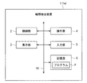
- FIG. 1 is a block diagram illustrating a hardware configuration of the contour extracting apparatus.
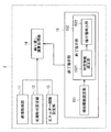
- FIG. 2 is a block diagram showing a configuration related to the contour extraction function.
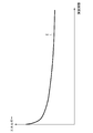
- FIG. 3 is a diagram schematically illustrating an energy function.
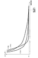
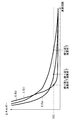
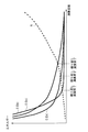
- FIG. 4 is a diagram schematically illustrating the auxiliary function.
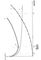
- FIG. 5 is a diagram schematically illustrating the determination function.
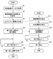
- FIG. 6 is a diagram illustrating a flow of processing executed in the contour extracting apparatus.
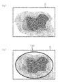
- FIG. 7 is a diagram schematically illustrating target image data and an initial dynamic curve set for the target image data.
- FIG. 8 is a diagram schematically showing a dynamic curve that is deformed in the process of repeated calculation.
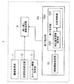
- FIG. 9 is a block diagram showing a configuration related to the contour extraction function.
- FIG. 9 is a block diagram showing a configuration related to the contour extraction function.
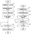
- FIG. 10 is a diagram illustrating a flow of processing executed in the contour extracting apparatus.
- FIG. 11 is a diagram for explaining processing executed by the end instruction unit.
- FIG. 12 is a diagram for explaining the end timing when a constant reference value is used.
- FIG. 13 is a diagram for explaining the end timing when a constant reference value is used.
- FIG. 14 is a diagram for explaining the end timing when the determination criterion function is used.
- FIG. 1 is a block diagram illustrating a hardware configuration of the contour extracting apparatus 1.
- the contour extracting device 1 extracts the contour of the object appearing in the image data to be processed (hereinafter referred to as “target image data”) using a dynamic contour model.
- the contour extraction apparatus 1 is configured by a general computer, and has a configuration in which a control unit 2, a display unit 3, an operation unit 4, an input unit 5, and a storage unit 6 are connected to a bus line 10.
- the control unit 2 is constituted by a CPU, for example, and determines the operation of the entire contour extracting device 1 by executing a program P stored in the storage unit 6, and gives a command to the entire contour extracting device 1.
- the display unit 3 is configured by a liquid crystal display or the like, and visually outputs image data generated by the control unit 2.
- the operation unit 4 includes a keyboard, a touch panel, a mouse, or the like, and transmits various command signals to the control unit 2 in accordance with various user operations.
- the input unit 5 inputs image data as target image data.
- the input unit 5 may acquire any image data.
- the image data may be received online from an external device, or the image data may be acquired by reading data from a portable storage medium such as a DVD or reading by a scanner.
- the image data may be acquired by storing the image data in a file server or the like connected via a network and reading the image data.
- the input image data is stored in the storage unit 6.
- the target image data is image data obtained by imaging natural objects (for example, animals including humans, plants, landscapes, etc.).
- the contour extracting device 1 is connected to a medical image photographing device, various image data captured by the medical image photographing device can be used as target image data.
- an ultrasonic imaging apparatus as one of the apparatuses widely used as medical imaging apparatuses.
- the ultrasonic imaging apparatus applies an ultrasonic wave of 2.5 MHz to 13.0 MHz to a predetermined part such as a built-in person of the subject to be imaged, and obtains an ultrasonic image of the part by visualizing the echo. If this ultrasonic imaging apparatus is connected to the contour extracting apparatus 1, an ultrasonic image representing the inside of the person to be imaged and the like imaged by the ultrasonic imaging apparatus is input via the input unit 5, and this is the target image. Data can be used.
- the storage unit 6 is configured by a storage device such as a semiconductor memory or a hard disk.
- the storage unit 6 stores various information such as a program P executed by the control unit 2, information necessary for executing the program P, and image data input from the input unit 5.
- the contour extracting apparatus 1 has a function (contour extracting function) for extracting the contour of an object appearing in target image data using a dynamic contour model.
- the dynamic contour model is a method of extracting the contour of the object while deforming the dynamic curve as described above.
- the energy function that minimizes the dynamic curve when the contour of the object is extracted is defined, and the energy function is minimized by iterative calculation to obtain a stable state where the value of the energy function is minimized.
- the contour of the object is extracted by finding it.
- FIG. 2 is a block diagram showing a configuration related to the contour extraction function.
- FIGS. 3 to 5 are referred to as appropriate.
- 3 to 5 are diagrams schematically illustrating the energy function E, the auxiliary function F, and the determination function G, respectively.
- the contour extraction apparatus 1 includes an image acquisition unit 11, an initial shape setting unit 12, an energy function setting unit 13, an iterative calculation processing unit 14, and an end instruction unit 15 as a configuration related to the contour extraction function.
- Each of these units may be realized by the control unit 2 performing arithmetic processing according to the program P stored in the storage unit 6, or may be realized by dedicated hardware.
- the image acquisition unit 11 acquires target image data. For example, among the image data stored in the storage unit 6, the one designated by the user is read out and acquired as target image data.
- the initial shape setting unit 12 sets the initial shape of the dynamic curve. Specifically, for example, the target image data is displayed on the display unit 3, and the shape input by the user from the operation unit 4 while viewing the display screen is received as the initial shape of the dynamic curve. In addition, one or more samples having an initial shape are stored in the storage unit 6, and the user selects one of the stored samples (or the name given to the target image data by the initial shape setting unit 12). Etc.), and the selected sample may be read out as the initial shape of the dynamic curve.
- the initial shape of the dynamic curve may be any shape, but in order to efficiently and accurately perform the processing related to contour extraction, it is preferable that the shape be as close as possible to the contour of the object. .
- the dynamic curve in the initial shape is hereinafter referred to as “initial dynamic curve”.
- the energy function setting unit 13 sets the energy function E.
- the energy function E is represented by a weighted linear sum of a plurality of types of energy terms defined corresponding to the state of the dynamic curve. The number of energy terms included in the energy function E and the contents of each energy term can be arbitrarily set. In this embodiment, two types of “internal energy term Ei” and “external energy term Ee” are used.
- the energy function E is defined using the energy term. That is, the energy function E according to this embodiment is a function represented by the following (formula 2). However, in (Expression 2), “Wi” and “We” represent weighting coefficients assigned to the internal energy term Ei and the external energy term Ee, respectively.
- the energy function E is formulated so that the value becomes smaller as the shape of the contour to be extracted becomes closer. That is, the internal energy term Ei and the external energy term Ee are formulated so that the values become smaller as the dynamic curve approaches the target shape. For example, the internal energy Ei is formulated so as to become smaller as the dynamic curve becomes smoother. Further, the external energy Ee is formulated so that the external energy Ee becomes a smaller value as the degree of coincidence between the dynamic curve and the contour of the object is higher.
- the user determines the values of the weighting coefficients Wi and We in consideration of the shape predicted as the contour of the target object, what form the contour of the target object is desired to be extracted, etc. It is assumed that the determined value is input to the contour extracting device 1 in advance (for example, in the initial setting of the contour extracting device 1). The value input by the user at this time is stored in the storage unit 6, and the energy function setting unit 13 reads the value and sets the energy function E. Note that the method of setting the weighting coefficients Wi and We is not limited to this.
- the values of the weighting coefficients Wi and We are stored in association with the samples of the initial shape, and the energy function setting unit 13 sets the values of the weighting factors Wi and We associated with the selected samples of the initial shape. It may be configured to read and set the energy function E.
- the repetitive calculation processing unit 14 performs the minimization process of the energy function E by repetitive calculation. That is, the dynamic curve is deformed along a deformation tendency defined by the energy function E by repeated calculation. Then, upon receiving an instruction (end instruction) to end the repeated calculation from the end timing determination unit 16 described later, the repeated calculation is ended, and the contour of the object is appropriately extracted from the dynamic curve at that time Obtained as a dynamic curve (hereinafter referred to as “final dynamic curve”).
- the end instruction unit 15 gives a repetitive calculation end instruction to the repetitive calculation processing unit 14 at a predetermined timing.
- the end instruction unit 15 includes an auxiliary function setting unit 151 and an end timing determination unit 152.
- the auxiliary function setting unit 151 sets a function (auxiliary function F) formulated so as to change according to the number of repetitions of the repeated calculation (hereinafter referred to as “the number of calculations”). Specifically, the auxiliary function F formulated so as to increase monotonously according to the number of operations is set. Therefore, the auxiliary function F is a function given by the following (formula 3) when the number of operations is represented as “n”.
- the auxiliary function F may be any function as long as it is a monotonically increasing function, but in this embodiment, as shown in FIG. It shall be defined by a function that increases accordingly.
- the end timing determination unit 152 determines the timing (end timing) for ending the repetitive calculation based on the transition of the energy function E and the change of the auxiliary function F in the process of the repetitive calculation.
- the end timing determination unit 152 includes a determination function setting unit 1521 and a minimum value detection unit 1522.
- the determination function setting unit 1521 sets a function (determination function G) represented by a linear sum of the energy function E and the auxiliary function F. That is, the determination function G is a function given by the following (formula 4).
- the energy function E is a function that decreases in the process of repeated calculation (see FIG. 3).
- the auxiliary function F is a function that increases in the process of repeated calculation (see FIG. 4). Therefore, the determination function G is a function having a minimum value m as schematically shown in FIG.
- the minimum value detection unit 1522 monitors the transition of the determination function G while the repetitive calculation is executed. As described above, the determination function G has a minimum value m somewhere in the process of repeated calculation. When the minimum value m is detected in the process of repetitive calculation, the minimum value detection unit 22 determines that time as the end timing.
- FIG. 6 is a diagram showing a flow of processing executed in the contour extracting apparatus 1.
- FIGS. 3 to 5 and FIGS. 7 and 8 are referred to as appropriate.
- FIG. 7A is a diagram schematically illustrating an example of target image data.
- FIG. 7B is a diagram schematically illustrating an example of an initial dynamic curve (initial dynamic curve T (0)) set for the target image data illustrated in FIG.
- FIG. 8 is a diagram schematically showing a dynamic curve that is deformed in the process of repeated calculation.
- FIG. 8A shows the dynamic curve T (n1) when the number of operations is n1 (see FIG.
- FIG. 8B shows the state when the number of operations is n2 (see FIG. 5).
- 8C shows the state of the dynamic curve T (n2)
- FIG. 8C shows the state of the dynamic curve T (n3) when the number of operations is n3 (see FIG. 5) (where n1). ⁇ N2 ⁇ n3).
- the image acquisition unit 11 acquires target image data (step S1).
- the image data Q of the ultrasonic image shown in FIG. 7A is acquired as the target image data.
- a blood vessel region appears dark, and here, it is assumed that this blood vessel is an object whose contour is to be extracted.
- the initial shape setting unit 12 sets the initial shape (initial dynamic curve) of the dynamic curve (step S2).
- the shape to be extracted is expected to be tubular.
- T (0) a tubular initial dynamic curve T (0) is set as shown in FIG.
- the energy function setting unit 13 sets the energy function E (step S3).
- the function represented by (Expression 2) is set as the energy function E.
- the iterative calculation processing unit 14 starts the minimization process of the energy function E by the iterative calculation (step S4).
- the value of the energy function E decreases (see FIG. 5).
- the initial dynamic curve T (0) set in step S2 is deformed and approaches the contour of the object (see FIG. 8).
- the repeated calculation processing unit 14 continues the calculation until an end instruction is given from the end instruction unit 15.
- the iterative calculation processing unit 14 ends the repetitive calculation (step S6).
- the dynamic curve obtained here is acquired as the final dynamic curve.
- auxiliary function setting unit 151 sets the auxiliary function F (see (Equation 3) and FIG. 4) (step S11).
- the determination function setting unit 1521 determines the determination function G (based on the energy function E (see (Equation 2) and FIG. 3) set in step S3) and the auxiliary function F set in step S11. (See Equation 4 and FIG. 5) (step S12).
- step S4 When the iterative arithmetic processing unit 14 starts the iterative arithmetic processing (step S4), the minimum value detecting unit 1522 starts monitoring the transition of the determination function G set in step S12 (step S13), and the determination function G is minimal. When it is detected that the value m has appeared (YES in step S14), that point is determined as the end timing, and an end instruction is repeatedly given to the arithmetic processing unit 14 (step S15).
- the end instruction unit 15 sets the determination function G represented by a linear sum of the energy function E of the dynamic curve and the auxiliary function F that changes according to the number of operations.
- the iterative arithmetic processing unit 14 terminates the repetitive arithmetic processing at the number of arithmetic operations (n2) when the minimum value m appears in the function F. At the end timing determined in this way, the accuracy of contour extraction and the calculation cost are reasonably balanced.
- the dynamic curve Tn2 that captures the contour of the object sufficiently accurately (although it is not perfect) is the final motion. Can be obtained as a target curve. Further, even if the calculation process is repeated more than this, such an inefficient calculation process is not performed where a shape change corresponding to the calculation cost cannot be expected in the dynamic curve.
- auxiliary function F by defining the auxiliary function F by a function whose increase rate increases with the number of operations, the calculation cost is excessively ensured while ensuring the accuracy of the minimum necessary contour extraction. Can be prevented.
- the contour extracting device 1a has a contour extracting function.
- a configuration for realizing the contour extraction function will be described with reference to FIG.
- FIG. 9 is a block diagram showing a configuration related to the contour extraction function. In the following, FIGS. 3 to 4 are referred to as appropriate.
- the contour extraction apparatus 1a includes the above-described image acquisition unit 11, initial shape setting unit 12, energy function setting unit 13, and repetitive calculation processing unit 14 as a configuration related to the contour extraction function. Moreover, it replaces with the completion
- Each of these units may be realized by the control unit 2 performing arithmetic processing according to the program P stored in the storage unit 6, or may be realized by dedicated hardware.
- the end instruction unit 15a gives a repetitive calculation end instruction to the repetitive calculation processing unit 14 at a predetermined timing.
- the end instruction unit 15a includes the auxiliary function setting unit 151 described above. Further, instead of the above-described end timing determination unit 152, an end timing determination unit 152a described below is provided.
- the end timing determination unit 152a determines the end timing based on the transition of the energy function E and the transition of the auxiliary function F during the iterative calculation process.
- the end timing determination unit 152a includes a determination criterion function acquisition unit 1523 and a comparison determination unit 1524.
- the determination criterion function acquisition unit 1523 acquires a function (determination criterion function H) that defines a value (reference value) serving as a criterion for determining whether or not the energy function E has converged in the iterative calculation.
- a function determination criterion function H
- the auxiliary function F set by the auxiliary function setting unit 151 is acquired as the determination reference function H. That is, the criterion function H is a function given by the following (formula 5).
- the auxiliary function F is a function that increases in the process of repeated calculation (see FIG. 4). Therefore, the criterion function H is also a function that increases in the process of repeated calculation. That is, the reference value becomes a large value as the repeated calculation proceeds.
- the comparison / determination unit 1524 monitors the transition of the energy function E while the repetitive calculation is being executed. When the value of the energy function E becomes smaller than the reference value defined by the determination reference function H (that is, the auxiliary function F), the energy function E is considered to have converged, and that point is determined as the end timing.
- FIG. 10 is a diagram showing a flow of processing executed in the contour extracting apparatus 1a. Note that FIG. 11 is referred to in the following description. FIG. 11 is a diagram for explaining processing executed by the end instruction unit.
- the determination criterion function acquisition unit 1523 acquires the auxiliary function F set in step S11 as the determination criterion function H (step S22).
- step S4 When the iterative arithmetic processing unit 14 starts the iterative arithmetic processing (step S4), the comparison determining unit 1524 starts monitoring the transition of the energy function E set in step S3 (step S23), and the value of the energy function E is changed.
- the value is smaller than the reference value defined by the determination reference function H (that is, the auxiliary function F) (YES in step S24)
- the energy function E is considered to have converged, and that time is determined as the end timing, and the repetitive calculation processing unit 14 Is given an end instruction (FIG. 11) (step S25).
- FIGS. 12 to 14 exemplifies three types of energy functions Ea, Eb, and Ec that change in different modes.
- the contour of the object can be extracted in the most appropriate form by continuing the calculation until the energy function E completely converges.
- a preset reference value may be used. That is, when the energy function E becomes smaller than a preset reference value, the energy function E is considered to have converged, and the calculation is repeated at that point.
- the value of the energy function E depends on the mode of change of the energy function E. May end in a state that is still far from convergence (for example, refer to the end timing of the iterative calculation of the energy function Ec). In such a case, the repetitive calculation ends before the dynamic curve captures the outline of the object sufficiently.
- the end instruction unit 15a uses the auxiliary function F that changes according to the number of calculations as the determination reference function H, and the value of the energy function E is greater than the reference value defined by the determination reference function H.
- the iterative arithmetic processing unit 14 ends the iterative arithmetic processing. At the end timing determined in this way, the accuracy of contour extraction and the calculation cost are reasonably balanced.
- the reference value is gradually changed to a larger value. Therefore, when the number of operations increases, even the energy function E that has not yet completely converged is actually converged. It is assumed that the calculation process is repeated. Therefore, even if the energy function E requires a considerable number of computations until it completely converges, the computation process can be terminated before the number of computations becomes excessively large (for example, repetition of the energy function Eb). Refer to the calculation end timing).
- auxiliary function F as a function whose increase rate increases with the number of computations, it is possible to ensure that the minimum necessary contour extraction accuracy is ensured and the calculation cost is excessive. Can be prevented.
- the auxiliary function F is defined by a function whose increase rate increases with the number of operations.
- the auxiliary function may be any function as long as it is a monotonically increasing function. There may be. For example, it may be a linear function or a quadratic function.
- contour extraction according to various purposes (applications) can be performed.
- auxiliary function F is set with a function having a relatively large increase rate, the contour of the object can be specified with a low calculation cost and a short calculation time. Therefore, such an auxiliary function F may be set in the case of an application in which the contour of the object may be rough and it is required to specify the calculation object with a low calculation cost and a short calculation time.
- the auxiliary function F is set with a function having a relatively small increase rate, the contour of the object can be accurately specified. Accordingly, since the calculation cost / calculation time may be required for the contour of the object, such an auxiliary function F may be set in the case of an application that requires accurate specification.
- the end instruction unit 15 is configured to determine the end timing using the determination function G.
- the determination function G used here is expressed by a linear sum of the energy function E and the auxiliary function F, but may be expressed by a weighted linear sum of these functions E and F.
- the determination function G is a function given by the following (formula 6).
- “Wf” represents a weighting coefficient added to the auxiliary function F.
- the value of the weighting coefficient Wf is a value that defines how to balance the accuracy of the contour extraction and the calculation cost, and for what purpose the contour extraction is performed (in what application the contour extraction is performed). It is desirable to set according to whether to do.
- the weighting coefficient Wf is set to a relatively large value, the influence of the auxiliary function F becomes large. Since the auxiliary function F is a force that tends to keep the number of repetitive calculations small (that is, in a direction to advance the end timing), in this case, it is possible to quickly extract the contour of the object while reducing the calculation cost. . Therefore, for example, when the contour extraction is used for an application in which the contour of the target object may be rough and thus it is required to quickly extract the calculation cost, the weighting coefficient Wf is set to a relatively large value. Just keep it.
- the weighting coefficient Wf is set to a relatively small value. Just set it up.
- the end instruction unit 15a is configured to determine the end timing using the determination reference function H.
- the auxiliary function F is used as it is as the determination criterion function H, but a function obtained by adding a coefficient to the auxiliary function F may be used as the determination criterion function H.
- the criterion function H is a function given by (Equation 7) below.
- “Wh” in (Expression 7) represents a coefficient attached to the auxiliary function F.
- the value of the coefficient Wh is a value that defines how the accuracy of contour extraction is balanced with the calculation cost, and depends on what purpose the contour extraction is performed for. It is desirable to set them.
- the coefficient Wh is set to a value larger than 1. Just keep it.
- the value of the coefficient Wh is smaller than 1, the value of the reference value that defines the end timing becomes a small value, so that the end timing is delayed.
- the contour of the object can be accurately extracted. Therefore, for example, when the contour extraction may be time-consuming or computationally expensive, and used in an application that requires the precise extraction of the contour of the object, the value of the coefficient Wh is set to a value smaller than 1. You just have to.
- the energy function E is a smooth function that decreases in the process of repetitive calculation, and the energy function E should be such a function.
- a slight fluctuation or the like may appear in the energy function E.
- the energy function E slightly increases momentarily. With such an energy function E including noise, there is a possibility that the end timing cannot be determined appropriately.
- an approximate energy function obtained by removing noise from the energy function E is acquired, and the approximate energy function is used instead of the energy function E.
- Any method may be used for obtaining the approximate energy function.
- the value of the energy function E may be sampled at a constant time interval to obtain discrete sampling data, and a curve defined by the obtained value may be obtained as an approximate energy function.
- a curve obtained by approximating the energy function E by the least square method or the like may be acquired as an approximate energy function.
Landscapes
- Engineering & Computer Science (AREA)
- Computer Vision & Pattern Recognition (AREA)
- Physics & Mathematics (AREA)
- General Physics & Mathematics (AREA)
- Theoretical Computer Science (AREA)
- Software Systems (AREA)
- Image Analysis (AREA)
Abstract
Description
〈1.ハードウェア構成〉
この発明の第1の実施の形態に係る輪郭抽出装置1のハードウェア構成について、図1を参照しながら説明する。図1は、輪郭抽出装置1のハードウェア構成を示すブロック図である。
輪郭抽出装置1は、対象画像データに現れる対象物の輪郭を、動的輪郭モデルを用いて抽出する機能(輪郭抽出機能)を備えている。ただし、動的輪郭モデルとは、上述した通り、動的曲線を変形させながら対象物の輪郭を抽出する方法である。具体的には、動的曲線が対象物の輪郭を抽出した時に最小となるエネルギー関数を定義し、繰り返し演算でこのエネルギー関数の最小化処理を行ってエネルギー関数の値が最小となる安定状態を見つけることによって、対象物の輪郭を抽出する。
輪郭抽出装置1において実行される処理の流れについて、図6を参照しながら説明する。図6は、輪郭抽出装置1において実行される処理の流れを示す図である。なお、以下の説明においては、図3~図5および図7、図8を適宜参照する。図7(a)は対象画像データの一例を模式的に示す図である。図7(b)は、図7(a)に示される対象画像データについて設定される初期動的曲線(初期動的曲線T(0))の一例を模式的に示す図である。図8は、繰り返し演算の過程で変形する動的曲線の様子を模式的に示した図である。特に、図8(a)は演算回数がn1回(図5参照)の際の動的曲線T(n1)の様子を、図8(b)は演算回数がn2回(図5参照)の際の動的曲線T(n2)の様子を、図8(c)は演算回数がn3回(図5参照)の際の動的曲線T(n3)の様子を、それぞれ示している(ただし、n1<n2<n3)。
はじめに、輪郭抽出装置1において実行される処理の全体の流れについて説明する。まず、画像取得部11が、対象画像データを取得する(ステップS1)。以下においては、図7(a)に示される超音波画像の画像データQが対象画像データとして取得されたとする。超音波画像においては、血管領域が暗く現れており、ここでは、この血管が、その輪郭を抽出すべき対象物であるとする。
次に、終了指示部15が実行する処理の流れについて説明する。繰り返し演算処理部14が繰り返し演算処理を開始するのに先立って、補助関数設定部151が補助関数F((式3)および図4参照)を設定する(ステップS11)。
図8に示されるように、繰り返し演算処理においては、演算回数が重ねられるにつれて動的曲線の形状が変形して対象物の輪郭に近づき、演算回数が多くなるほど対象物の輪郭が適確に抽出される。したがって、輪郭抽出の適確性という面から見ると、図5に示されるように、エネルギー関数Eが完全に収束する演算回数n3まで繰り返し演算を続け、この際の動的曲線T(n3)を、最終動的曲線として取得することが望ましい。ところが、多くの場合、エネルギー関数Eは、図3に示されるように収束が近づくにつれて変化がなだらかとなるため、演算回数が大きくなってくると、計算コストに見合うだけの変形が動的曲線に起こらない。一方で、計算コストを小さくするために、例えば、比較的少ない演算回数n1で繰り返し演算を終了してしまうと、エネルギー関数Eがまだ十分に小さな値となっていないので、対象物の輪郭を十分に捉えられていない動的曲線T(n1)が最終動的曲線として取得されることになってしまう。このように、輪郭抽出処理において、輪郭抽出の適確性と計算コストとを妥当にバランスさせるためには、繰り返し演算処理を終了するタイミングが重要となってくる。
この発明の第2の実施の形態に係る輪郭抽出装置1aについて説明する。なお、以下においては、先に説明したものと同じ構成要素については同じ参照符号で示し、その説明を省略する。
輪郭抽出装置1aのハードウェア構成は、第1の実施の形態に係る輪郭抽出装置1と同様であるのでその説明を省略する(図1参照)。
輪郭抽出装置1aは、第1の実施の形態に係る輪郭抽出装置1と同様、輪郭抽出機能を備えている。輪郭抽出機能を実現するための構成について、図9を参照しながら説明する。図9は、輪郭抽出機能に関する構成を示すブロック図である。なお、以下においては、図3~図4を適宜参照する。
輪郭抽出装置1aにおいて実行される処理の流れについて、図10を参照しながら説明する。図10は、輪郭抽出装置1aにおいて実行される処理の流れを示す図である。なお、以下の説明においては、図11を参照する。図11は、終了指示部が実行する処理を説明するための図である。
輪郭抽出装置1aにおいて実行される処理の全体の流れ(ステップS1~ステップS6)は、第1の実施の形態と同様である。
終了指示部15aが実行する処理の流れについて説明する。繰り返し演算処理部14が繰り返し演算処理を開始するのに先立って、補助関数設定部151が補助関数F((式3)および図4参照)を設定する(ステップS21)。
上記の実施の形態に係る輪郭抽出装置1aから得られる効果について図12~図14を参照しながら説明する。図12~図14の各図には、それぞれ異なる態様で変化する3種類のエネルギー関数Ea,Eb,Ecが例示されている。
〈1.第1の変形例〉
上記の各実施の形態においては、補助関数Fが、増加率が演算回数に応じて大きくなる関数により規定されるものとしたが、補助関数は単調増加関数であればどのような形の関数であってもよい。例えば、一次関数であってもよいし、二次関数であってもよい。
第1の実施の形態に係る終了指示部15は、判定関数Gを用いて終了タイミングを判定する構成としていた。ここで用いられる判定関数Gは、エネルギー関数Eと補助関数Fとの線形和により表されるものとしたが、これら関数E,Fの重み付け線形和により表されるものであってもよい。例えば、補助関数Fに重み付け係数を付加した場合、判定関数Gは、下記(式6)で与えられる関数となる。ただし、(式6)中、「Wf」は、補助関数Fに付される重み付け係数を表している。
第2の実施の形態係る終了指示部15aは、判定基準関数Hを用いて終了タイミングを判定する構成していた。上記においては、補助関数Fをそのまま判定基準関数Hとして用いる構成としたが、補助関数Fに係数を付した関数を、判定基準関数Hとして用いる構成としてもよい。この場合、判定基準関数Hは、下記(式7)で与えられる関数となる。ただし、(式7)中「Wh」は、補助関数Fに付される係数を表している。
上記の各実施の形態においては、エネルギー関数Eが、繰り返し演算の過程で減少する滑らかな関数であることが前提となっており、本来、エネルギー関数Eはそのような関数であるはずである。ところが、実際の実装態様においては、エネルギー関数Eにわずかな振れ等(ノイズ)現れる場合がある。例えば、繰り返し演算の途中で再初期化処理が行われた場合、エネルギー関数Eが瞬間的に微増してしまう。このようなノイズを含むエネルギー関数Eでは、適切に終了タイミングを決定することができない可能性がある。
上記の各実施の形態は、各種の動的輪郭モデル(例えば、レベルセット、スネーク等)を用いて対象物の輪郭を抽出する輪郭抽出装置に適用することができる。
2 制御部
11 画像取得部
12 初期形状設定部
13 エネルギー関数設定部
14 繰り返し演算処理部
15,15a 終了指示部
151 補助関数設定部
152,152a 終了タイミング判断部
1521 判定関数設定部
1522 極小値検出部
1523 判定基準関数取得部
1524 比較判断部
P プログラム
Claims (6)
- 動的輪郭モデルを用いて対象物の輪郭を抽出する輪郭抽出装置であって、
自然物を撮像して得られた対象画像を取得する画像取得部と、
前記対象画像に表れる対象物の輪郭を抽出するための動的曲線の初期形状を設定する初期形状設定部と、
前記動的曲線の状態に対応して定義される複数種類のエネルギー項の重み付き線形和により表され、抽出すべき輪郭の形状に近づくほど、その値が小さくなるように定式化されたエネルギー関数を設定するエネルギー関数設定部と、
前記エネルギー関数を繰り返し演算により最小化させる繰り返し演算部と、
前記繰り返し演算の繰り返し回数に応じて変化するように定式化された補助関数を設定する補助関数設定部と、
前記繰り返し演算の過程における前記エネルギー関数の変移と、前記繰り返し演算の過程における前記補助関数の変移とに基づいて、前記繰り返し演算を終了する終了タイミングを判断する終了タイミング判断部と、
を備えることを特徴とする輪郭抽出装置。 - 請求項1に記載の輪郭抽出装置であって、
前記補助関数が、前記繰り返し回数に応じて単調増加するように定式化された関数であることを特徴とする輪郭抽出装置。 - 請求項2に記載の輪郭抽出装置であって、
前記補助関数が、その増加率が前記繰り返し回数に応じて大きくなる関数であることを特徴とする輪郭抽出装置。 - 請求項2に記載の輪郭抽出装置であって、
前記終了タイミング判断部が、
前記エネルギー関数と前記補助関数との線形和により表される判定関数を設定する判定関数設定部、
を備え、
前記繰り返し演算の過程で前記判定関数に極小値が現れた時点を、前記終了タイミングと判断することを特徴とする輪郭抽出装置。 - 請求項2に記載の輪郭抽出装置であって、
前記終了タイミング判断部が、
前記繰り返し演算の過程で前記エネルギー関数の値が前記補助関数の値よりも小さくなった時点を、前記終了タイミングと判断することを特徴とする輪郭抽出装置。 - コンピュータに記憶され、前記コンピュータにおいて実行されることにより、前記コンピュータを、動的輪郭モデルを用いて対象物の輪郭を抽出する輪郭抽出装置として機能させるプログラムであって、前記輪郭抽出装置が、
自然物を撮像して得られた対象画像を取得する画像取得部と、
前記対象画像に表れる対象物の輪郭を抽出するための動的曲線の初期形状を設定する初期形状設定部と、
前記動的曲線の状態に対応して定義される複数種類のエネルギー項の重み付き線形和により表され、抽出すべき輪郭の形状に近づくほど、その値が小さくなるように定式化されたエネルギー関数を設定するエネルギー関数設定部と、
前記エネルギー関数を繰り返し演算により最小化させる繰り返し演算部と、
前記繰り返し演算の繰り返し回数に応じて変化するように定式化された補助関数を設定する補助関数設定部と、
前記繰り返し演算の過程における前記エネルギー関数の変移と、前記繰り返し演算の過程における前記補助関数の変移とに基づいて、前記繰り返し演算を終了する終了タイミングを判断する終了タイミング判断部と、
を備えることを特徴とするプログラム。
Priority Applications (4)
| Application Number | Priority Date | Filing Date | Title |
|---|---|---|---|
| EP10796951.1A EP2453413A4 (en) | 2009-07-09 | 2010-03-18 | DEVICE AND PROGRAM FOR EXTRACTING CONTOURS |
| CN201080030463.2A CN102473309B (zh) | 2009-07-09 | 2010-03-18 | 轮廓提取装置以及程序 |
| US13/379,520 US8532392B2 (en) | 2009-07-09 | 2010-03-18 | Contour extraction device and program |
| JP2011521847A JP5299511B2 (ja) | 2009-07-09 | 2010-03-18 | 輪郭抽出装置およびプログラム |
Applications Claiming Priority (2)
| Application Number | Priority Date | Filing Date | Title |
|---|---|---|---|
| JP2009162613 | 2009-07-09 | ||
| JP2009-162613 | 2009-07-09 |
Publications (1)
| Publication Number | Publication Date |
|---|---|
| WO2011004640A1 true WO2011004640A1 (ja) | 2011-01-13 |
Family
ID=43429065
Family Applications (1)
| Application Number | Title | Priority Date | Filing Date |
|---|---|---|---|
| PCT/JP2010/054676 Ceased WO2011004640A1 (ja) | 2009-07-09 | 2010-03-18 | 輪郭抽出装置およびプログラム |
Country Status (5)
| Country | Link |
|---|---|
| US (1) | US8532392B2 (ja) |
| EP (1) | EP2453413A4 (ja) |
| JP (1) | JP5299511B2 (ja) |
| CN (1) | CN102473309B (ja) |
| WO (1) | WO2011004640A1 (ja) |
Families Citing this family (4)
| Publication number | Priority date | Publication date | Assignee | Title |
|---|---|---|---|---|
| US9875581B2 (en) * | 2014-10-31 | 2018-01-23 | The Regents Of The University Of California | Automated 3D reconstruction of the cardiac chambers from MRI or ultrasound |
| KR101724338B1 (ko) * | 2015-09-15 | 2017-04-07 | 전자부품연구원 | 강인한 영역 분리 방법 및 이를 적용한 시스템 |
| JP6204634B1 (ja) * | 2015-12-25 | 2017-09-27 | 楽天株式会社 | 形状弁別装置、形状弁別方法及び形状弁別プログラム |
| CN120876521B (zh) * | 2025-07-22 | 2026-03-17 | 北京大学人民医院 | 基于三维数据采集的分发梳轮廓确定方法、介质及设备 |
Citations (3)
| Publication number | Priority date | Publication date | Assignee | Title |
|---|---|---|---|---|
| JPH05342353A (ja) * | 1992-06-10 | 1993-12-24 | Oki Electric Ind Co Ltd | 輪郭抽出方法 |
| JPH07320068A (ja) * | 1994-05-24 | 1995-12-08 | Toshiba Corp | 画像処理方法及び画像処理装置 |
| JP2000339452A (ja) * | 1999-05-27 | 2000-12-08 | Canon Inc | 画像抽出方法及び装置並びに記憶媒体 |
Family Cites Families (8)
| Publication number | Priority date | Publication date | Assignee | Title |
|---|---|---|---|---|
| US5594849A (en) * | 1991-08-09 | 1997-01-14 | Yale University | Biomedical magnetism imaging apparatus and method |
| JP3850076B2 (ja) | 1996-04-24 | 2006-11-29 | 富士写真フイルム株式会社 | 動的輪郭抽出方法 |
| CN1480903A (zh) * | 1996-08-29 | 2004-03-10 | ������������ʽ���� | 特征信息赋予、物体抽取和立体模型生成方法及其装置 |
| US6031935A (en) * | 1998-02-12 | 2000-02-29 | Kimmel; Zebadiah M. | Method and apparatus for segmenting images using constant-time deformable contours |
| US6674905B1 (en) * | 1999-01-22 | 2004-01-06 | Canon Kabushiki Kaisha | Image processing method, image processing apparatus, and storage medium |
| CN1169079C (zh) * | 2002-03-25 | 2004-09-29 | 北京工业大学 | 基于样条思内克斯(Snakes)模型的中医舌象计算机分割方法 |
| US7022073B2 (en) * | 2003-04-02 | 2006-04-04 | Siemens Medical Solutions Usa, Inc. | Border detection for medical imaging |
| US7706610B2 (en) * | 2005-11-29 | 2010-04-27 | Microsoft Corporation | Segmentation of objects by minimizing global-local variational energy |
-
2010
- 2010-03-18 US US13/379,520 patent/US8532392B2/en not_active Expired - Fee Related
- 2010-03-18 JP JP2011521847A patent/JP5299511B2/ja not_active Expired - Fee Related
- 2010-03-18 EP EP10796951.1A patent/EP2453413A4/en not_active Withdrawn
- 2010-03-18 CN CN201080030463.2A patent/CN102473309B/zh not_active Expired - Fee Related
- 2010-03-18 WO PCT/JP2010/054676 patent/WO2011004640A1/ja not_active Ceased
Patent Citations (3)
| Publication number | Priority date | Publication date | Assignee | Title |
|---|---|---|---|---|
| JPH05342353A (ja) * | 1992-06-10 | 1993-12-24 | Oki Electric Ind Co Ltd | 輪郭抽出方法 |
| JPH07320068A (ja) * | 1994-05-24 | 1995-12-08 | Toshiba Corp | 画像処理方法及び画像処理装置 |
| JP2000339452A (ja) * | 1999-05-27 | 2000-12-08 | Canon Inc | 画像抽出方法及び装置並びに記憶媒体 |
Non-Patent Citations (1)
| Title |
|---|
| See also references of EP2453413A4 * |
Also Published As
| Publication number | Publication date |
|---|---|
| JPWO2011004640A1 (ja) | 2012-12-20 |
| CN102473309A (zh) | 2012-05-23 |
| EP2453413A1 (en) | 2012-05-16 |
| US8532392B2 (en) | 2013-09-10 |
| EP2453413A4 (en) | 2015-03-18 |
| US20120099799A1 (en) | 2012-04-26 |
| JP5299511B2 (ja) | 2013-09-25 |
| CN102473309B (zh) | 2014-09-24 |
Similar Documents
| Publication | Publication Date | Title |
|---|---|---|
| CN110009640B (zh) | 处理心脏视频的方法、设备和可读介质 | |
| CN109308469B (zh) | 用于生成信息的方法和装置 | |
| Hamarneh et al. | Combining snakes and active shape models for segmenting the human left ventricle in echocardiographic images | |
| JP2020042028A (ja) | コレクターの相対パラメータのキャリブレーション方法、装置、機器及び媒体 | |
| CN109977905B (zh) | 用于处理眼底图像的方法和装置 | |
| CN112649773B (zh) | 磁共振扫描方法、装置、设备及存储介质 | |
| JP5299511B2 (ja) | 輪郭抽出装置およびプログラム | |
| JP2010108496A (ja) | データをあらわす属性を選択する方法、コンピューター読み取り可能な媒体、生成モデルを形成する方法および生成モデルを形成するシステム | |
| CN113902684A (zh) | 图像分割方法及装置、电子设备、存储介质 | |
| WO2024022301A1 (zh) | 视角路径获取方法、装置、电子设备及介质 | |
| CN110232401B (zh) | 基于图片转换的病灶判断方法、装置、计算机设备 | |
| WO2019134685A1 (zh) | 示波器数据处理方法、装置及示波器 | |
| CN110288668A (zh) | 图像生成方法、装置、计算机设备及存储介质 | |
| JP5182228B2 (ja) | 輪郭抽出装置およびプログラム | |
| CN113760087A (zh) | 命中点位置信息的确定方法和装置 | |
| CN116993812B (zh) | 冠脉血管中心线的提取方法、装置、设备及存储介质 | |
| CN112530004B (zh) | 一种三维点云重建方法、装置及电子设备 | |
| CN115862654A (zh) | 语音降噪方法及装置 | |
| WO2022181253A1 (ja) | 関節点検出装置、学習モデル生成装置、関節点検出方法、学習モデル生成方法、及びコンピュータ読み取り可能な記録媒体 | |
| KR102201177B1 (ko) | 서포트 벡터 회귀 모델을 이용한 혈압 측정 장치 및 방법 | |
| EP4610938A1 (en) | Displaying a medical image | |
| WO2025181004A1 (en) | Displaying a medical image | |
| CN117041676A (zh) | 一种视频剪辑切换方法、装置、设备及存储介质 | |
| CN119888067A (zh) | 一种人体三维扫描数据的特征提取方法及其系统 | |
| WO2024059125A1 (en) | System and method for processing multi-dimensional ultrasound imaging data on real-time cloud computers |
Legal Events
| Date | Code | Title | Description |
|---|---|---|---|
| WWE | Wipo information: entry into national phase |
Ref document number: 201080030463.2 Country of ref document: CN |
|
| 121 | Ep: the epo has been informed by wipo that ep was designated in this application |
Ref document number: 10796951 Country of ref document: EP Kind code of ref document: A1 |
|
| WWE | Wipo information: entry into national phase |
Ref document number: 13379520 Country of ref document: US |
|
| WWE | Wipo information: entry into national phase |
Ref document number: 2011521847 Country of ref document: JP |
|
| REEP | Request for entry into the european phase |
Ref document number: 2010796951 Country of ref document: EP |
|
| WWE | Wipo information: entry into national phase |
Ref document number: 2010796951 Country of ref document: EP |
|
| NENP | Non-entry into the national phase |
Ref country code: DE |
|
| WWE | Wipo information: entry into national phase |
Ref document number: 1201004423 Country of ref document: TH |