WO2011004727A1 - 静電容量検出装置 - Google Patents
静電容量検出装置 Download PDFInfo
- Publication number
- WO2011004727A1 WO2011004727A1 PCT/JP2010/060974 JP2010060974W WO2011004727A1 WO 2011004727 A1 WO2011004727 A1 WO 2011004727A1 JP 2010060974 W JP2010060974 W JP 2010060974W WO 2011004727 A1 WO2011004727 A1 WO 2011004727A1
- Authority
- WO
- WIPO (PCT)
- Prior art keywords
- switching control
- capacitance
- switch
- time
- change
- Prior art date
- Legal status (The legal status is an assumption and is not a legal conclusion. Google has not performed a legal analysis and makes no representation as to the accuracy of the status listed.)
- Ceased
Links
Images


Classifications
-
- G—PHYSICS
- G01—MEASURING; TESTING
- G01D—MEASURING NOT SPECIALLY ADAPTED FOR A SPECIFIC VARIABLE; ARRANGEMENTS FOR MEASURING TWO OR MORE VARIABLES NOT COVERED IN A SINGLE OTHER SUBCLASS; TARIFF METERING APPARATUS; MEASURING OR TESTING NOT OTHERWISE PROVIDED FOR
- G01D5/00—Mechanical means for transferring the output of a sensing member; Means for converting the output of a sensing member to another variable where the form or nature of the sensing member does not constrain the means for converting; Transducers not specially adapted for a specific variable
- G01D5/12—Mechanical means for transferring the output of a sensing member; Means for converting the output of a sensing member to another variable where the form or nature of the sensing member does not constrain the means for converting; Transducers not specially adapted for a specific variable using electric or magnetic means
- G01D5/14—Mechanical means for transferring the output of a sensing member; Means for converting the output of a sensing member to another variable where the form or nature of the sensing member does not constrain the means for converting; Transducers not specially adapted for a specific variable using electric or magnetic means influencing the magnitude of a current or voltage
- G01D5/24—Mechanical means for transferring the output of a sensing member; Means for converting the output of a sensing member to another variable where the form or nature of the sensing member does not constrain the means for converting; Transducers not specially adapted for a specific variable using electric or magnetic means influencing the magnitude of a current or voltage by varying capacitance
-
- G—PHYSICS
- G01—MEASURING; TESTING
- G01R—MEASURING ELECTRIC VARIABLES; MEASURING MAGNETIC VARIABLES
- G01R27/00—Arrangements for measuring resistance, reactance, impedance, or electric characteristics derived therefrom
- G01R27/02—Measuring real or complex resistance, reactance, impedance, or other two-pole characteristics derived therefrom, e.g. time constant
- G01R27/26—Measuring inductance or capacitance; Measuring quality factor, e.g. by using the resonance method; Measuring loss factor; Measuring dielectric constants ; Measuring impedance or related variables
- G01R27/2605—Measuring capacitance
-
- H—ELECTRICITY
- H03—ELECTRONIC CIRCUITRY
- H03K—PULSE TECHNIQUE
- H03K17/00—Electronic switching or gating, i.e. not by contact-making and –breaking
- H03K17/94—Electronic switching or gating, i.e. not by contact-making and –breaking characterised by the way in which the control signals are generated
- H03K17/96—Touch switches
- H03K17/962—Capacitive touch switches
-
- H—ELECTRICITY
- H03—ELECTRONIC CIRCUITRY
- H03K—PULSE TECHNIQUE
- H03K2217/00—Indexing scheme related to electronic switching or gating, i.e. not by contact-making or -breaking covered by H03K17/00
- H03K2217/94—Indexing scheme related to electronic switching or gating, i.e. not by contact-making or -breaking covered by H03K17/00 characterised by the way in which the control signal is generated
- H03K2217/96—Touch switches
- H03K2217/9607—Capacitive touch switches
- H03K2217/96071—Capacitive touch switches characterised by the detection principle
- H03K2217/960725—Charge-transfer
Definitions
- the present invention relates to a capacitance detection device that detects an unknown capacitance to be measured.
- a locking system Smart Entry that communicates between a portable device carried by the user and the main unit on the vehicle side, authenticates the portable device, and controls to automatically unlock and lock the door.
- US2007 / 0216175A1 specification Patent Document 1 describes a door by a user such as a user touching a door handle arranged on the door after authenticating the portable device between the in-vehicle device and the portable device.
- Patent Document 1 describes a door by a user such as a user touching a door handle arranged on the door after authenticating the portable device between the in-vehicle device and the portable device.
- a vehicle door handle technology that detects an operation on the handle and locks and unlocks the door is described.
- the door handle incorporates a capacitance detection device that detects that a human hand approaches or contacts the door handle (see Patent Document 1: [0025] to [0030], etc.).
- the capacitance detection device is configured by a switched capacitor system as described in, for example, US 7,015,705 B2 specification (Patent Document 2).
- the time for which the switch provided between the measured capacitance and the reference capacitance is closed is set to several times the time constant represented by the product of the ON resistance of the switch and the measured capacitance. This reduces a decrease in sensitivity when there is a leak resistance in the capacitance to be measured, such as in a high humidity environment or when the surface of the capacitance detection device has water suitability (Patent Document 2: Column 5). (See line 16 to column 7, line 17 etc.)
- the electrostatic capacitance detection device of Patent Document 2 is excellent in that it can reduce the influence of sensitivity reduction when a leak resistance exists in the measured capacitance.
- a capacitance detection device mounted on a door handle of a locking system such as Patent Document 1
- the door is locked and unlocked regardless of the user's intention to lock and unlock.
- a possibility of being there is a possibility of being.
- a capacitance detection device that can distinguish between changes in capacitance due to external factors such as water droplets and human operations, and that can detect the presence of the human operations with a simple configuration. It is.
- the characteristic configuration of the capacitance detection device is as follows.
- a first switch disposed between both ends of a reference capacitor having one end connected to a first potential source;
- a second switch having one end disposed between the other end of the measured capacitance connected to the second potential source or free space and the other end of the reference capacitance;
- a third switch disposed between both ends of the measured capacitance;
- An operation of returning the first switch to the open state after the initialization time has elapsed after closing the first switch is referred to as a first switch operation, and an operation of returning the open state to the open state after the first charging time has elapsed after the second switch is closed.
- the first switching control is a control in which the second switch operation and the third switch operation are alternately repeated, After performing the first switch operation, a second switching control is performed to alternately repeat the second switch operation with a second charging time different from the first charging time and the third switch operation with a second discharging time.
- a switch controller that alternately and repeatedly executes the first switching control and the second switching control;
- a potential determination unit that determines whether the potential at the other end of the reference capacitor has changed from an initial potential after the first switch operation to a predetermined set potential by the first switching control and the second switching control;
- a counting unit for counting the number of repetitions of the second switch operation until the potential at the other end of the reference capacitor changes to the set potential by the first switching control and the second switching control; Based on the number of repetitions counted in at least one of the first switching control and the second switching control, the presence or absence of a change in the capacitance value of the measured capacitance is determined, and the first switching control
- An output determination unit for determining whether or not the change in the capacitance value of the measured capacitance is caused by an event to be detected based on the number of repetitions and the number of repetitions in the second switching control; In the point provided with.
- two types of closing times of the second switch were set.
- two types of switching control are executed corresponding to two types of closing times of the second switch, and the number of repetitions of the second switch operation is counted. For example, when the time constant is short, the number of repetitions of the second switch operation in the first switching control and the second switching control is the same regardless of the closing time of the second switch.
- the first discharge time is set to a time longer than the first charge time
- the second discharge time is set to a time longer than the second charge time
- the first discharge time is set to a time longer than the first charge time and the second discharge time is set to a time longer than the second charge time, there is no remaining capacity in the measured capacity, and each time the second switch is operated, it is accurate. Is charged. As a result, a highly accurate capacitance detection device can be obtained.
- a change amount calculation unit that calculates, as a change amount, a difference from the previous number of repetitions of the second switch operation in each of the first switching control and the second switching control that are repeatedly executed.
- the output determination unit determines whether or not a capacitance value of the measured capacitance has changed based on the change amount of at least one of the first switching control and the second switching control, and the first switching control. It is preferable to determine whether or not the change in the capacitance value of the measured capacitance is caused by an event to be detected based on the change amount in the second switching control and the change amount in the second switching control. is there.
- the change amount calculation unit calculates the difference from the previous number of repetitions of the second switch operation in each of the first switching control and the second switching control that are repeatedly executed as the change amount.
- the output determination unit determines whether or not there is a change in the capacitance value of the measured capacitance based on at least one of the number of repetitions in each of the first switching control and the second switching control.
- the number of repetitions is affected by environmental temperature and the like.
- the amount of change is the difference in the number of repetitions under conditions where the surrounding environment such as the ambient temperature is substantially the same, so that the influence of the surrounding environment can be almost ignored.
- the output determination unit determines whether or not there is a change in the capacitance value of the measured capacitance based on at least one of the amount of change in each of the first switching control and the second switching control, it is possible to determine with high accuracy. Become. Similarly, the determination as to what event has occurred can be performed with high accuracy.
- the output determination unit is configured to reduce the capacitance of the measured capacity based on the amount of change in which the second switch operation is performed in a short charging time out of the first charging time and the second charging time. It is preferable to determine whether there is a change in the capacitance value.
- the change in capacitance per unit time when an event with a long time constant occurs is smaller than when an event with a short time constant occurs. That is, the change in capacitance per first and second charging time is smaller when an event with a long time constant occurs than when an event with a short time constant occurs. For this reason, when an event with a long time constant occurs, the amount of change in the number of repetitions of the second switch operation is also reduced. If the charging time, which is the closing time of the second switch, is short, in the event of a long time constant, the change in capacitance is further reduced, and the amount of change in the number of repetitions of the second switch operation is also reduced.
- the output determination unit may detect a change in the capacitance value of the measured capacitance based on a ratio or difference between the change amount in the first switching control and the change amount in the second switching control. It is preferable to determine whether or not it is caused by an event that becomes.
- the output determination unit appropriately determines what event has occurred by comparing the number of repetitions of the second switch operation and the amount of change in the first switching control and the second switching control. can do.
- a comparison method a simple determination can be made by using the difference.
- the ratio as a comparison method, the tolerance to environmental changes is increased, and an accurate determination is possible.
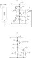
- FIG. 1 is a circuit configuration diagram schematically showing an example of a capacitance detection device according to the present invention.
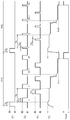
- Timing chart schematically showing an operation example of the capacitance detection device Flow chart schematically showing an example of the operation procedure of the capacitance detection device.
- the figure which shows typically the equivalent circuit example of the electrostatic capacitance detection apparatus when a person touches The figure which shows typically the equivalent circuit example of the electrostatic capacitance detection apparatus at the time of a water drop attaching
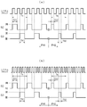
- a diagram explaining the difference in volume change between when a person touches and when a water drop is attached Timing chart showing an example of switching timing control method
- the capacitance detection device detects capacitance by a switched capacitor system having a reference capacitance Cs, a measured capacitance Cx1, and three switches S1, S2, and S3. .
- the first switch S1 is disposed between both ends (between T1 and T2) of the reference capacitor Cs having one end (T1) connected to the first potential source (V1).
- the second switch S2 has one end (T4) between the other end (T3) of the measured capacitance Cx1 connected to the second potential source (V2) or free space and the other end (T2) of the reference capacitance Cs. Placed in.
- the third switch S3 is disposed between both ends (between T3 and T4) of the measured capacitance Cx1.
- the other end (T2) of the reference capacitor Cs is connected to the inverting input terminal of the comparator 7 constituted by an operational amplifier.
- a predetermined set potential Vref is connected to the non-inverting input terminal of the comparator 7.
- the comparator 7 outputs the potential determination signal Vout at a high level when the potential at the other end (T2) of the reference capacitor Cs changes from the initial potential to a predetermined set potential Vref.
- the initial potential is the first potential source V1.
- the comparator 7 corresponds to the potential determination unit of the present invention.
- the three switches S1 to S3 are controlled to be opened and closed by the control circuit 10 as shown in FIG.
- the control circuit 10 is configured by a logic circuit such as a microcomputer or an ASIC (application specific integrated circuit).
- a configuration in which the control circuit 10 is configured with a microcomputer as a core is illustrated.
- the CPU 11, the program memory 12, the work memory (work register) 13, and the parameter memory (parameter register) 14 are illustrated, but other peripheral circuits (not shown) are also included in the control circuit 10.
- the CPU 11, the program memory 12, the work memory (work register) 13, and the parameter memory (parameter register) 14 may naturally be integrated in one microcomputer.
- control circuit 10 various functional units are realized by the cooperation of hardware such as the CPU 11 and software stored in the program memory 12, the parameter memory 14, or the like.
- control circuit 10 is configured to include functional units such as a switch control unit 1, a count unit 2, an output determination unit 3, and a change amount calculation unit 4.
- the switch control unit 1 repeatedly executes the first switching control PH1 and the second switching control PH2 shown in FIG. 2 alternately.
- the first switching control PH1 and the second switching control PH2 are controls for alternately repeating a second switch operation and a third switch operation described later after performing a first switch operation described later.
- the first switch operation is a process of returning the first switch S1 to the open state after the initialization time T10 has elapsed since the first switch S1 is closed as shown in FIG. 2, and the same applies to the first switching control PH1 and the second switching control PH2. It is processing.
- the second switch operation and the third switch operation as described later, there is a difference in the closing time between the first switching control PH1 and the second switching control PH2.
- the second switch operation is a process of returning the second switch S2 to the open state after the first charging time T21 has elapsed since the second switch S2 is closed.
- the third switch operation is a process for returning the open state after the first discharge time T31 has elapsed since the third switch S3 was closed.
- the second switch operation is performed by a second charging time T22 that is different from the first charging time T21.
- the third switch operation is a process of returning the open state after the second discharge time T32 has elapsed since the third switch S3 was closed.
- the first discharge time T31 and the second discharge time T32 may be the same time or different times as long as the measured capacity Cx1 can be sufficiently discharged.
- the first discharge time T31 is set to a time equal to or longer than the first charge time 21 and the second discharge time T32 is set to a time equal to or longer than the second charge time T22, it is preferable that the measured capacitance Cx1 is reliably discharged.
- the first charging time T21 is longer than the second charging time T22, and the first discharging time T31 is longer than the second discharging time T32.
- the first charging time T21 and the first discharging time T31 may be set to the same length of time, and the second charging time T22 and the second discharging time T32 may be set to the same length of time.
- the first discharge time T31 is a time equal to or longer than the first charge time 21 and the second discharge time T32 is equal to or longer than the second charge time T22, the measured capacitance Cx1 is discharged well.
- the first switch S1 is closed and then the first switch is returned to the open state after the initialization time T10 has elapsed, so that the potential of the terminal T2 of the reference capacitor Cs is the first potential that is the initial potential. It becomes the potential of the potential source V1.
- the second switch operation and the third switch operation are alternately repeated, whereby the potential of the terminal T2 is lowered.
- the potential determination signal Vout is output from the comparator 7, and the control circuit 10 receives this potential determination signal Vout.
- the control circuit 10 can specify a period from when the first switch is operated until the potential determination signal Vout is received.
- the count unit 2 is realized in the control circuit 10 as a functional unit that counts the number of repetitions (N1, N2) of the second switch operation while the potential of the terminal T2 of the reference capacitor Cs changes from the initial potential to the set potential Vref.
- the repeat count N1 is the repeat count in the first switching control PH1
- the repeat count N2 is the repeat count in the second switching control PH2.
- the circuit configuration diagram of FIG. 1 shows a circuit when a person or a water droplet is not touching the detection unit of the capacitance detection device.
- the measurement electrode of the capacitance Cx1 to be measured and the person or water drop
- the coupling capacitance (Cx2), human capacitance (Ch), human resistance (Rh), and water drop resistance (Rw) are included.
- the output determination unit 3 is a functional unit that determines whether there is a change in the capacitance value of the measured capacitance Cx1 based on at least one of the number of repetitions N1 and N2.
- the output determination unit 3 is a functional unit that detects that a person touches the detection unit of the capacitance detection device or that a water droplet or the like has adhered.
- the number of repetitions N1 and N2 is also affected by the environmental temperature.
- the equivalent circuit differs between when a person touches it and when a water drop or the like adheres, and the circuit constants are also different, but both may be confused.
- the output determination unit 3 determines whether the change in the capacitance value of the measured capacitance Cx1 is caused by an event to be detected based on the number of repetitions N1 and the number of repetitions N2. It has a function of determining whether or not. That is, it is determined whether or not the change in the capacitance value of the measured capacitance Cx1 is due to human contact based on the number of repetitions N1 and the number of repetitions N2. As will be described later, the number of times of repetition N1 and the number of times of repetition N2 under the condition that the closing time of the second switch S2 (the first charging time T21 and the second charging time T22) are different are almost the same value when a person contacts.
- the change amount calculation unit 4 calculates the difference ( ⁇ N1, ⁇ N2) from the previous difference in the number of repetitions (N1, N2) of the second switch operation in each of the first switching control PH1 and the second switching control PH2 that are repeatedly executed. ) Is a functional unit that calculates as As described above, the output determination unit 3 determines whether there is a change in the capacitance value of the measured capacitance Cx1 based on at least one of the number of repetitions N1 and N2. However, the number of repetitions N1 and N2 may be affected by environmental temperature or the like. On the other hand, the amount of change ⁇ N1 or ⁇ N2 is the difference in the number of repetitions under conditions where the ambient environment such as the environmental temperature is substantially the same.
- the ambient environment such as the environmental temperature hardly changes in a short time such as the interval between the previous time and the current time of the first and second switching control, and thus the change amounts ⁇ N1 and ⁇ N2 are the number of repetitions under substantially the same conditions. It can be considered a difference. Therefore, by using the change amounts ⁇ N1 and ⁇ N2, the influence of the surrounding environment can be almost ignored in the determination by the output determination unit 3. Therefore, when the output determination unit 3 determines the presence or absence of a change in the capacitance value of the measured capacitance Cx1 based on at least one of the change amounts ⁇ N1 and ⁇ N2, determination with high accuracy becomes possible.
- the output determination unit 3 compares the change amount ⁇ N1 and the change amount ⁇ N2 to determine whether or not the change in the capacitance value of the measured capacitance Cx1 is caused by an event to be detected. it can. In this case, as in the case of determining whether or not the capacitance value of the measured capacitance Cx1 has changed, the influence of the surrounding environment can be almost ignored. For example, the output determination unit 3 determines whether the event is to be detected based on the ratio or difference between the change amount ⁇ N1 in the first switching control PH1 and the change amount ⁇ N2 in the second switching control PH2.
- the second switch S2 is in a closed state during the first charging time T21 during the first switching control PH1.
- the second switch S2 is closed during a second charging time T22 that is shorter than the first charging time T21.
- the closing time of the third switch S3 is equal to the first discharging time T31 during the first switching control PH1 during the second switching control PH2.
- the first charging time T21 and the first discharging time T31 can be the same time
- the second charging time T22 and the second discharging time T32 can be the same time.
- the first discharge time T31 and the second discharge time T32 may be the same length. It is sufficient that the first discharge time T31 and the second discharge time T32 are set to a time during which the measured capacitance Cx1 can be discharged, and it is necessary to set the first discharge time T31 and the second discharge time T31 according to the first charge time T21 and the first discharge time T31. Not.
- the second switch S2 and the third switch S3 are controlled so as to be alternately closed.
- the time during which the second switch S2 is closed is different in the first switching control PH1 and the second switching control PH2, but the control cycle Ts is the same. That is, the second switch S2 and the third switch S3 are controlled at a constant frequency and with different pulse widths. Therefore, even if the two phases of the first switching control PH1 and the second switching control PH2 are provided, it is possible to suppress an increase in the number of parts and an increase in circuit scale, such as provision of a plurality of oscillators. . Details will be described later with reference to FIG.
- step # 1 is executed by the cooperation of the CPU 11, the program memory 12, the work memory (work register) 13, the parameter memory (parameter register) 14, and the like.
- step # 1 the initialization time T10, the first charging time T21, the first discharging time T31, etc. stored in the parameter memory 14 are used.
- a change amount ⁇ N1 that is a difference between the number of repetitions N1 measured in the previous step # 1 and the latest number of repetitions N1 is calculated (step # 2).
- the calculated change amount ⁇ N1 is temporarily stored in, for example, a work memory (work register) 13 that is temporary storage means.
- the number of repetitions N1 is also temporarily stored in the work memory 13.
- step # 3 the second switching control PH2 described above is executed, and the number of repetitions N2 of the second switch operation is measured (step # 3).
- step # 3 the initialization time T10, the second charging time T22, the second discharging time T32, etc. stored in the parameter memory 14 are used.
- step # 4 a change amount ⁇ N2 that is a difference between the repeat count N2 measured in the previous step # 3 and the latest repeat count N2 is calculated (step # 4).
- the calculated change amount ⁇ N2 is temporarily stored in, for example, the work memory 13 which is temporary storage means.
- the number of repetitions N2 is also temporarily stored in the work memory 13.
- step # 5 If it is determined “No” in step # 5, the process returns to step # 1, and steps # 1 to # 5 are executed again. If “Yes” is determined in step # 5, that is, if the first determination condition is satisfied, the second determination condition is verified. That is, whether the change in the capacitance value of the measured capacitance Cx1 is caused by an event to be detected based on the number of repetitions N1 in the first switching control PH1 and the number of repetitions N2 in the second switching control PH2. It is determined whether or not (step # 6). Two conditions can be taken for this determination. In the flowchart of FIG. 3, two conditions are written together by logical sum. However, any one of the two conditions only needs to be satisfied. May be determined.
- One of the conditions in parallel is the ratio between the change amount ⁇ N1 and the change amount ⁇ N2.
- step # 6 for example, an example is shown in which the condition is satisfied when ( ⁇ N1 / ⁇ N2) is equal to or less than the threshold value TH2.
- the ratio is approximately 1: 1.
- the change amount ⁇ N2 in the second switching control PH2 with a short closing time (second charging time T22) of the second switch S2 is smaller than the change amount ⁇ N1 (details will be described later).
- the ratio between the change amount ⁇ N1 and the change amount ⁇ N2 is greatly deviated from 1: 1.
- ( ⁇ N1 / ⁇ N2) is larger. Therefore, by setting a condition that is satisfied when ( ⁇ N1 / ⁇ N2) is equal to or less than the threshold value TH2, it is possible to determine that the condition is not satisfied in the case of water droplet adhesion.
- the other condition in parallel is the difference between the change amount ⁇ N1 and the change amount ⁇ N2.
- the amount of change ⁇ N1 and the amount of change ⁇ N2 do not differ greatly, and the difference is almost zero.
- the change amount ⁇ N2 is smaller than the change amount ⁇ N1, and the difference is increased. Therefore, by setting the condition that is satisfied when ( ⁇ N1 ⁇ N2) is equal to or less than the threshold value TH3, it is possible to determine that the condition is not satisfied in the case of adhesion of water droplets.
- step # 7 When the condition of step # 5 is satisfied and any of the conditions of step # 6 is satisfied, a detection result is output (step # 7). For example, a detection result that there is a human contact is output.
- the measured capacitance Cx1 increases in capacity by ⁇ C with a time constant ⁇ shown below.
- ⁇ Rh ⁇ (Cx2 ⁇ Ch) / (Cx2 + Ch)
- ⁇ C (Cx2 ⁇ Ch) / (Cx2 + Ch)
- the number of repetitions N1 and N2 until the potential of the terminal T2 of the reference capacitor Cs becomes a predetermined potential decreases.
- this reduction amount is large, the above-described ⁇ N1 and ⁇ N2 are equal to or greater than the threshold value TH1.
- the coupling capacitor Cx2 is formed between the electrode of the capacitor to be measured and the water droplet.
- the detection electrode is attached to the inside of the door handle, resin exists between the electrode of the capacitance to be measured and the exterior of the door handle. Since water droplets adhere to the exterior surface of the door handle and a person comes in contact with the exterior, the coupling capacity Cx2 is substantially the same for both human and water droplets. On the other hand, resistance is greatly different between people and water drops. In the case of a water drop, for example, since it is short-circuited to the body of an automobile, an electrostatic capacity corresponding to human electrostatic capacity Ch does not occur.
- the presence or absence of a change in the measured capacitance Cx1 may be determined using only one of them, or may be determined using both.
- the amount of change ⁇ N2 of the number of repetitions N2 of the second switching control PH2 in which the second switch S2 is closed in the second charging time T22 shorter than the first charging time T21 is greater than ⁇ N1.
- the degree of change may be small. Therefore, in this embodiment, only the change amount ⁇ N2 is used for determination in order to increase tolerance to erroneous determination, shorten calculation time, and simplify the configuration of the capacitance detection device such as a program (step # 5). .
- the electrostatic capacitance detection device provided on the door handle of the vehicle door, the principle by which a human operation (contact with a finger or the like) and water droplet adhesion can be distinguished by the above-described configuration and processing will be described.
- the size of the electrode when the measured capacitance Cx1 is built in the door handle of the vehicle door is, for example, about 100 mm 2
- the coupling capacitance Cx2 is several pF (for example, 1 pF).
- the human resistance Rh is several k ⁇ (eg, 2 k ⁇ ) and the capacitance Ch is several hundred pF (eg, 200 pF).
- Rh ⁇ (Cx2 ⁇ Ch) / (Cx2 + Ch) 2k ⁇ 1p ⁇ 200p / (1p + 200p) ⁇ 2 n [s]
- the resistance Rw is several hundreds k ⁇ , although it is influenced by the amount of water and water quality.
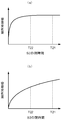
- FIG. 6A is a graph schematically showing an increase in capacity in the case of a person
- FIG. 6B is a graph schematically showing an increase in capacity in the case of a water drop. It can be seen that the capacity change is quick when the person has a small time constant ⁇ (close proximity), and the capacity change is slow when the water droplet has a large time constant ⁇ .
- the first charging time T21 which is the longer of the first and second charging times that are the closing time of the second switch S2 can sufficiently change the capacity in both cases of humans and water drops.
- a time constant ⁇ in the case of a water drop is preferably around 300 ns.
- the second charging time T22 which is the shorter of the first charging time and the second charging time, can sufficiently change the capacity in the case of contact (proximity) of a person as an event to be detected.
- the time is set at a time when the capacity change is insufficient.
- the second charging time T22 is set to a time during which the capacity change in the case of a water droplet is in progress as shown in FIG.
- the second charging time T22 exceeds 2 ns, which is the time constant ⁇ for humans, and is sufficiently shorter than 300 ns, which is the time constant ⁇ for water drops, for example, about 150 ns. Is preferably set. Of course, it may be set to a shorter time, for example, about several tens of ns including an environmental error.
- the closing time of the third switch S3 may be a time sufficient for discharging the detected capacitor Cx1. Therefore, it can be set without necessarily depending on the first charging time T21 and the second charging time T22, which are the closing times of the second switch S2.
- the number of switching times counted by the counting unit 2 is substantially the same in the first switching control PH1 and the second switching control PH2. That is, the difference between the count numbers N1 and N2 is small, and the ratio is close to 1. Similarly, the difference between the change amounts ⁇ N1 and ⁇ N2 is small, and the ratio is close to 1.
- the degree of change in capacity differs between when the second switch S2 switches at the first charging time T21 and when it switches at the second charging time T22.
- the number of times of switching N2 in the second charging time T22 with a small increase in capacity is larger than that of N1. Therefore, the number of times of switching counted by the counting unit 2 is a value that differs greatly between the first switching control PH1 and the second switching control PH2. That is, the difference between the count numbers N1 and N2 is large, and the ratio is also different from 1. Similarly, the difference between the change amounts ⁇ N1 and ⁇ N2 is large, and the ratio is also different from 1.
- the difference between the switching times N1 and N2 in the first switching control PH1 and the second switching control PH2 is larger or smaller than a threshold value, is human contact (proximity)? It is possible to determine whether the water droplets are attached. For example, when it is equal to or less than a predetermined threshold value, it can be determined that the contact is not human but water contact.
- a predetermined threshold value it can be determined that the contact is not human but water contact.
- the same change can be made based not on the switching times N1 and N2 but on the change amounts ⁇ N1 and ⁇ N2. By using the amount of change, it is possible to increase resistance to environmental changes and the like (see step # 6).
- the same determination can be made based not on the switching times N1 and N2 but on the changes ⁇ N1 and ⁇ N2.
- the change amount ⁇ N1 at the time of the first switching control PH1 in which the number of times of switching is reduced is larger than ⁇ N2. Therefore, for example, depending on whether or not the value of ( ⁇ N1 / ⁇ N2) is smaller than a predetermined threshold value (for example, TH2), it is determined whether it is human contact (proximity) or adhesion of water droplets. (See step # 6).
- the amount of change ⁇ N2 is smaller than the amount of change ⁇ N2 when a water droplet adheres, compared with the case where a person touches. Therefore, in step # 5 shown in FIG. 3, the change amount ⁇ N2 is used instead of the amount of change ⁇ N1. As a result, the determination accuracy is improved. That is, when a water droplet adheres, there is a high possibility that the amount of change ⁇ N2 is less than the predetermined threshold value TH1. There is nothing. Therefore, the tolerance with respect to the human contact which is a detection object event becomes high.
- the switching period Ts of the second switch S2 and the third switch S3 is the same in the first switching control PH1 and the second switching control PH2. That is, the switching frequency is the same.
- An example of a method for generating such switching timing will be supplemented with reference to FIG.
- the switching period Ts is equal to three system clock periods in the first switching control PH1 and the second switching control PH2, and is the same time.
- the second switch S2 and the third switch S3 are controlled by using both rising and falling edges of the system clock.
- the present invention is not limited to this, and control may be performed using only one of the edges (for example, the rising edge) as shown in FIG.
- the switching cycle for such a control form is also possible to change the switching cycle for such a control form.
- the first switching control PH1 and the second switching control PH2 are configured by completely the same logic circuit and program, and the clock frequency for driving the logic circuit and the CPU clock for executing the program are changed.
- the closing time (corresponding to the first charging time T21 and the second charging time T22) of the second switch S2 which has a different switching cycle due to the change of the clock frequency, also becomes a different time.
- a plurality of clocks must be provided and the clocks must be switched using another circuit or program, which increases the scale of the capacitance detection device and increases costs. Therefore, as shown in the present embodiment, it is preferable to make the closing times different in the same switching period Ts.
- a change in capacitance due to external factors such as water droplets and an artificial operation can be distinguished well, and the static operation that can be detected with a simple configuration can be detected. It is possible to provide a capacitance detection device.
- Such a capacitance detection device communicates between a portable device carried by the user and the vehicle main body, authenticates the portable device, and automatically unlocks and locks the door. It can be used in a locking system that controls to perform. Specifically, in such a locking system, it can be used as a sensor that detects an artificial operation of the user based on whether or not the door handle is operated.
- Switch control unit 2 Count unit 3: Output determination unit 4: Change amount calculation unit 7: Comparator (potential determination unit)
- T2 Terminal of the first switch (the other end of the first switch)
- T3 Terminal of the second switch (the other end of the second switch)
- Vref Set potential ⁇ N1, ⁇ N2: Amount of change
Landscapes
- Physics & Mathematics (AREA)
- General Physics & Mathematics (AREA)
- Geophysics And Detection Of Objects (AREA)
- Measurement Of Resistance Or Impedance (AREA)
- Electronic Switches (AREA)
- Investigating Or Analyzing Materials By The Use Of Electric Means (AREA)
Abstract
水滴などの外部要因と人為的操作とによる静電容量の変化を良好に区別して、人為的操作があったことを簡素な構成で検出可能な静電容量検出装置を提供する。 それぞれ異なる充電時間で第2スイッチ操作を行う第1スイッチング制御と第2スイッチング制御とを交互に繰り返し実行する。基準容量の端子の電位が設定電位まで変化するまでの第2スイッチ操作の繰り返し回数を両スイッチング制御のそれぞれにおいてカウントする。両スイッチング制御の少なくとも一方の繰り返し回数に基づいて、被測定容量の変化の有無を判定すると共に、両スイッチング制御の繰り返し回数に基づいて被測定容量の変化が被検出対象となる事象に起因するものであるか否かを判定する。
Description
本発明は、未知の被測定容量を検出する静電容量検出装置に関する。
利用者が携帯する携帯機と車両側の本体機との間で通信を行い、当該携帯機の認証を行って、自動的にドアの解錠や施錠を行うように制御するロッキングシステム(スマートエントリーシステム)が知られている。US2007/0216175A1明細書(特許文献1)には、車載機と携帯機との間で携帯機の認証を行った後、ドアに配接されたドアハンドルへ利用者が触れるなど、利用者によるドアハンドルへの操作を検出してドアの施解錠を行う車両用のドアハンドルの技術が記載されている。ドアハンドルには、人の手が当該ドアハンドルに接近又は接触したことを検出する静電容量検出装置などが内蔵されている(特許文献1:[0025]~[0030]等参照。)。
静電容量検出装置は、例えば、US7,015,705B2明細書(特許文献2)に記載されたようなスイッチトキャパシタ方式によって構成される。ここで、被測定容量と基準容量との間に設けられたスイッチを閉状態とする時間は、当該スイッチのオン抵抗と被測定容量の積で表される時定数の数倍に設定される。これにより、高湿度環境下や静電容量検出装置の表面に水適が付いた状態など、被測定容量にリーク抵抗が存在した場合の感度低下が低減される(特許文献2:第5欄第16行~第7欄第17行等参照。)。
特許文献2の静電容量検出装置は、被測定容量にリーク抵抗が存在した場合の感度低下の影響を軽減することが可能な優れたものである。しかし、被測定容量に水などが付着した瞬間には、人が触れたことと、水などが付着したこととの区別ができない可能性がある。例えば、特許文献1のようなロッキングシステムのドアハンドルに搭載された静電容量検出装置では、降雨や洗車などによって水が掛かった際に、ユーザーの施解錠の意志とは無関係にドアが施解錠されてしまう可能性がある。
上記課題に鑑み、水滴などの外部要因と人為的操作とによる静電容量の変化を良好に区別して、当該人為的操作があったことを簡素な構成で検出可能な静電容量検出装置が望まれる。
上記課題に鑑みた本発明に係る静電容量検出装置の特徴構成は、
一方端が第1の電位源に接続された基準容量の両端間に配置された第1スイッチと、
一方端が第2の電位源もしくは自由空間に接続された被測定容量の他方端と前記基準容量の他方端との間に配置された第2スイッチと、
前記被測定容量の両端間に配置された第3スイッチと、
前記第1スイッチを閉状態にしてから初期化時間経過後に開状態に戻す操作を第1スイッチ操作とし、前記第2スイッチを閉状態にしてから第1充電時間経過後に開状態に戻す操作を第2スイッチ操作とし、前記第3スイッチを閉状態にしてから第1放電時間経過後に開状態に戻す操作を第3スイッチ操作とし、
前記第1スイッチ操作を行った後、前記第2スイッチ操作と前記第3スイッチ操作とを交互に繰り返す制御を第1スイッチング制御とし、
前記第1スイッチ操作を行った後、前記第1充電時間とは異なる第2充電時間による前記第2スイッチ操作と第2放電時間による前記第3スイッチ操作とを交互に繰り返す制御を第2スイッチング制御として、
前記第1スイッチング制御と前記第2スイッチング制御とを交互に繰り返し実行するスイッチ制御部と、
前記第1スイッチング制御及び前記第2スイッチング制御によって前記基準容量の他方端の電位が前記第1スイッチ操作後の初期電位から所定の設定電位まで変化したか否かを判定する電位判定部と、
前記第1スイッチング制御及び前記第2スイッチング制御によって前記基準容量の他方端の電位が前記設定電位まで変化するまでの前記第2スイッチ操作の繰り返し回数をそれぞれカウントするカウント部と、
前記第1スイッチング制御及び前記第2スイッチング制御の少なくとも一方においてカウントされた前記繰り返し回数に基づいて、前記被測定容量の静電容量値の変化の有無を判定すると共に、前記第1スイッチング制御における前記繰り返し回数と前記第2スイッチング制御における前記繰り返し回数とに基づいて前記被測定容量の静電容量値の変化が被検出対象となる事象に起因するものであるか否かを判定する出力判定部と、を備える点にある。
発明者らは、当該静電容量検出装置が搭載される装置に対して、人が接触や接近した場合と水滴などが付着した場合となどの異なる事象が生じた時、被測定容量が異なる時定数で変化することに着目し、第2スイッチの閉時間を2種類設定した。本特徴構成によれば、第2スイッチの2種類の閉時間に対応して、2種類のスイッチング制御が実行され、第2スイッチ操作の繰り返し回数がそれぞれカウントされる。例えば、上記時定数が短い場合には、第2スイッチの閉時間に拘わらず、第1スイッチング制御と第2スイッチング制御とにおける第2スイッチ操作の繰り返し回数は同等となる。一方、上記時定数が長い場合には、第2スイッチの閉時間に応じて、第1スイッチング制御と第2スイッチング制御とにおける第2スイッチ操作の繰り返し回数が異なる可能性が高くなる。従って、第1スイッチング制御と第2スイッチング制御とにおける第2スイッチ操作の繰り返し回数を比較することによって、どのような事象が生じたのかを良好に判定することができる。また、繰り返し回数に基づいて、被測定容量に変化が生じたか否かを判定することができる。従って、本特徴構成によれば、被測定容量に変化が生じたか否かが判定できると共に、変化を生じさせた事象が被検出対象となる事象に起因するものであるか否かを判定することができる。その結果、水滴などの外部要因と人為的操作とによる静電容量の変化を良好に区別して、当該人為的操作があったことを簡素な構成で検出可能な静電容量検出装置が提供される。
ここで、前記第1放電時間は前記第1充電時間以上の時間に設定され、前記第2放電時間は前記第2充電時間以上の時間に設定されると好適である。
第1放電時間が第1充電時間以上の時間に設定され、第2放電時間が第2充電時間以上の時間に設定されると、被測定容量に残存容量がなくなり、第2スイッチ操作において毎回正確な充電が行われる。その結果、精度の高い静電容量検出装置が得られる。
ここで、さらに、繰り返し実行される前記第1スイッチング制御と前記第2スイッチング制御とのそれぞれにおける前記第2スイッチ操作の繰り返し回数の前回との差を変化量として演算する変化量演算部が備えられ、
前記出力判定部が、前記第1スイッチング制御及び前記第2スイッチング制御の少なくとも一方の前記変化量に基づいて前記被測定容量の静電容量値の変化の有無を判定すると共に、前記第1スイッチング制御における前記変化量と前記第2スイッチング制御における前記変化量とに基づいて前記被測定容量の静電容量値の変化が被検出対象となる事象に起因するものであるか否かを判定すると好適である。
前記出力判定部が、前記第1スイッチング制御及び前記第2スイッチング制御の少なくとも一方の前記変化量に基づいて前記被測定容量の静電容量値の変化の有無を判定すると共に、前記第1スイッチング制御における前記変化量と前記第2スイッチング制御における前記変化量とに基づいて前記被測定容量の静電容量値の変化が被検出対象となる事象に起因するものであるか否かを判定すると好適である。
変化量演算部により、繰り返し実行される第1スイッチング制御と第2スイッチング制御とのそれぞれにおける第2スイッチ操作の繰り返し回数の前回との差が変化量として演算される。上述したように、出力判定部は、第1スイッチング制御と第2スイッチング制御とのそれぞれにおける繰り返し回数の少なくとも一方に基づいて、被測定容量の静電容量値の変化の有無を判定する。但し、これらの繰り返し回数は環境温度などの影響を受ける。これに対して変化量は、環境温度などの周囲環境がほぼ同一の条件下における繰り返し回数の差であるから、周囲環境の影響をほぼ無視することができる。従って、出力判定部が、第1スイッチング制御と第2スイッチング制御とのそれぞれにおける変化量の少なくとも一方に基づいて被測定容量の静電容量値の変化の有無を判定すると高い精度の判定が可能となる。同様に、どのような事象が生じたのかについての判定も、精度良く実施することが可能となる。
ここで、前記出力判定部は、前記第1充電時間と前記第2充電時間との内、短い充電時間により前記第2スイッチ操作が行われる方の前記変化量に基づいて前記被測定容量の静電容量値の変化の有無を判定すると好適である。
時定数が長い事象が生じた時の単位時間当たりの静電容量の変化は、時定数が短い事象が生じた時に比べて小さくなる。つまり、第1及び第2充電時間当たりの静電容量の変化は、時定数が短い事象が生じた時に比べて時定数が長い事象が生じた時の方が小さい。このため、時定数が長い事象が生じた時には、第2スイッチ操作の繰り返し回数の変化量も少なくなる。第2スイッチの閉時間である充電時間が短ければ、時定数が長い事象の場合には、静電容量の変化がさらに少なくなり、第2スイッチ操作の繰り返し回数の変化量も少なくなる。従って、短い充電時間により第2スイッチ操作が行われる方の変化量に基づいて被測定容量の静電容量値の変化の有無を判定することで、時定数が長い事象が発生した場合には、未検出として扱うことが可能となる。例えば、当該静電容量検出装置が搭載される装置に対して、人が接触や接近した場合と水滴などが付着した場合とでは、水滴などが付着した場合に時定数が長くなる。つまり、時定数が長い事象が発生した場合には水滴などである可能性が高いので、事象の判別を実施することと合わせて、静電容量の変化の有無の判定基準を厳しくすることによって、事象の検出精度を向上させることが可能となる。
また、前記出力判定部は、前記第1スイッチング制御における前記変化量と前記第2スイッチング制御における前記変化量との比又は差に基づいて前記被測定容量の静電容量値の変化が被検出対象となる事象に起因するものであるか否かを判定すると好適である。
上述したように、出力判定部は、第1スイッチング制御と第2スイッチング制御とにおける第2スイッチ操作の繰り返し回数やその変化量を比較することによって、どのような事象が生じたのかを良好に判定することができる。比較の方法として、差を用いることによって、簡単な判定が可能となる。また、比較の方法として、比を用いることによって、環境変化に対する耐力が高くなり、精度のよい判定が可能となる。
以下、本発明の実施形態を図面に基づいて説明する。図1に示すように、本発明に係る静電容量検出装置は、基準容量Csと、被測定容量Cx1と、3つのスイッチS1、S2、S3とを有するスイッチトキャパシタ方式により静電容量を検出する。第1スイッチS1は、一方端(T1)が第1の電位源(V1)に接続された基準容量Csの両端間(T1-T2間)に配置される。第2スイッチS2は、一方端(T4)が第2の電位源(V2)もしくは自由空間に接続された被測定容量Cx1の他方端(T3)と基準容量Csの他方端(T2)との間に配置される。第3スイッチS3は、被測定容量Cx1の両端間(T3-T4間)に配置される。
基準容量Csの他方端(T2)は、演算増幅器によって構成されるコンパレータ7の反転入力端子に接続される。コンパレータ7の非反転入力端子には、所定の設定電位Vrefが接続されている。コンパレータ7は、基準容量Csの他方端(T2)の電位が初期電位から所定の設定電位Vrefまで変化した際に、電位判定信号Voutをハイレベルで出力する。後述するように、初期電位は、第1の電位源V1である。コンパレータ7は、本発明の電位判定部に相当する。
3つのスイッチS1~S3は、図1に示すように、制御回路10によって開閉制御される。制御回路10は、マイクロコンピュータやASIC(application specific integrated circuit)などの論理回路などによって構成される。本実施形態では、1つの好適な構成として、マイクロコンピュータを中核として制御回路10が構成される形態を例示している。ここでは、CPU11と、プログラムメモリ12と、ワークメモリ(ワークレジスタ)13と、パラメータメモリ(パラメータレジスタ)14とを例示しているが、その他不図示の周辺回路なども制御回路10に含まれる。また、CPU11、プログラムメモリ12、ワークメモリ(ワークレジスタ)13、パラメータメモリ(パラメータレジスタ)14は、当然1つのマイクロコンピュータに集積されていてもよい。
制御回路10において、CPU11などのハードウェアと、プログラムメモリ12やパラメータメモリ14などに格納されたソフトウェアとの協働により、種々の機能部が実現される。本実施形態においては、制御回路10は、スイッチ制御部1と、カウント部2と、出力判定部3と、変化量演算部4との各機能部を備えて構成される。
スイッチ制御部1は、図2に示す第1スイッチング制御PH1と、第2スイッチング制御PH2とを交互に繰り返し実行する。第1スイッチング制御PH1及び第2スイッチング制御PH2は、後述する第1スイッチ操作を行った後、後述する第2スイッチ操作と第3スイッチ操作とを交互に繰り返す制御である。第1スイッチ操作は、図2に示すように第1スイッチS1を閉状態にしてから初期化時間T10経過後に開状態に戻す処理であり、第1スイッチング制御PH1及び第2スイッチング制御PH2において同様の処理である。第2スイッチ操作及び第3スイッチ操作に関しては、後述するように、第1スイッチング制御PH1及び第2スイッチング制御PH2において、閉時間に違いがある。
図2に示すように、第1スイッチング制御PH1において、第2スイッチ操作は、第2スイッチS2を閉状態にしてから第1充電時間T21経過後に開状態に戻す処理である。第1スイッチング制御PH1において、第3スイッチ操作は、第3スイッチS3を閉状態にしてから第1放電時間T31経過後に開状態に戻す処理である。第2スイッチング制御PH2において、第2スイッチ操作は、第1充電時間T21とは異なる第2充電時間T22により実施される。第2スイッチング制御PH2において、第3スイッチ操作は、第3スイッチS3を閉状態にしてから第2放電時間T32経過後に開状態に戻す処理である。第1放電時間T31及び第2放電時間T32は、被測定容量Cx1が充分に放電可能な時間であれば、同じ時間でもよいし、異なる時間でもよい。第1放電時間T31が第1充電時間21以上の時間に設定され、第2放電時間T32が第2充電時間T22以上の時間に設定されると被測定容量Cx1が確実に放電されて好適である。本実施形態では、第1充電時間T21は第2充電時間T22よりも長い時間であり、第1放電時間T31は第2放電時間T32よりも長い時間である。制御を容易にするために、第1充電時間T21と第1放電時間T31とを同じ長さの時間とし、第2充電時間T22と第2放電時間T32とを同じ長さの時間にしてもよい。この場合も、第1放電時間T31は第1充電時間21以上の時間であり、第2放電時間T32は第2充電時間T22以上の時間であるので被測定容量Cx1は良好に放電される。
図2に示すように、第1スイッチS1を閉状態にしてから初期化時間T10経過後に開状態に戻す第1スイッチ操作により、基準容量Csの端子T2の電位は、初期電位である第1の電位源V1の電位となる。第1スイッチ操作の後、第2スイッチ操作と第3スイッチ操作とが交互に繰り返されることによって、端子T2の電位は低下していく。端子T2の電位が設定電位Vrefまで変化すると、コンパレータ7から電位判定信号Voutが出力され、制御回路10はこの電位判定信号Voutを受け取る。制御回路10は、第1スイッチ操作から、電位判定信号Voutを受け取るまでの期間を特定することができる。カウント部2は、基準容量Csの端子T2の電位が初期電位から設定電位Vrefまで変化する間の第2スイッチ操作の繰り返し回数(N1,N2)をカウントする機能部として、制御回路10において実現される。ここで、繰り返し回数N1は、第1スイッチング制御PH1における繰り返し回数であり、繰り返し回数N2は、第2スイッチング制御PH2における繰り返し回数である。
図1の回路構成図は、静電容量検出装置の検出部に人や水滴などが触れていない場合の回路を示している。図4及び図5に示す等価回路を用いて後述するように、静電容量検出装置の検出部に人が触れたり、水滴が付着したりすると、被測定容量Cx1の測定電極と人や水滴とのカップリング容量(Cx2)や、人の容量(Ch)、人の抵抗(Rh)や水滴の抵抗(Rw)を含む回路となる。その結果、上述した繰り返し回数(N1,N2)が変化するので、静電容量検出装置の検出部に人が触れたり、水滴などが付着したりしたことを検出することが可能である。
出力判定部3は、繰り返し回数N1及びN2の少なくとも一方に基づいて、被測定容量Cx1の静電容量値の変化の有無を判定する機能部である。つまり、出力判定部3は、静電容量検出装置の検出部に人が触れたり、水滴などが付着したりしたことを検出する機能部である。但し、被測定容量Cx1の静電容量値の変化の有無だけでは、人が触れたことと、水滴などが付着したこととが明確に区分できない場合がある。静電容量は、環境温度などの影響を受け易いことから、繰り返し回数N1及びN2も環境温度による影響を受ける。図4及び図5の等価回路に示すように、人が触れた場合と水滴などが付着した場合とでは等価回路が異なり、また、回路定数も異なるものの、両者を混同する可能性がある。
そこで、本発明に係る出力判定部3は、さらに、繰り返し回数N1と繰り返し回数N2とに基づいて被測定容量Cx1の静電容量値の変化が被検出対象となる事象に起因するものであるか否かを判定する機能を有して構成される。つまり、繰り返し回数N1と繰り返し回数N2とに基づいて被測定容量Cx1の静電容量値の変化が、人の接触によるものか否かを判定する。後述するように、第2スイッチS2の閉時間(第1充電時間T21及び第2充電時間T22)が異なる条件での繰り返し回数N1と繰り返し回数N2とは、人が接触した場合にはほぼ同じ値となるが、水滴が付着した場合には差が生じる。従って、繰り返し回数N1と繰り返し回数N2とを比較することによって、被測定容量Cx1の静電容量値の変化が被検出対象となる事象に起因するものであるか否かを判定することができる。
変化量演算部4は、繰り返し実行される第1スイッチング制御PH1と第2スイッチング制御PH2とのそれぞれにおける第2スイッチ操作の繰り返し回数(N1,N2)の前回との差を変化量(ΔN1,ΔN2)として演算する機能部である。上述したように、出力判定部3は、繰り返し回数N1及びN2の少なくとも一方に基づいて、被測定容量Cx1の静電容量値の変化の有無を判定する。しかし、この繰り返し回数N1及びN2は環境温度などの影響を受ける可能性がある。これに対し、変化量ΔN1やΔN2は、環境温度などの周囲環境がほぼ同一の条件下における繰り返し回数の差である。つまり、環境温度などの周囲環境は、第1及び第2スイッチング制御の前回と今回とのインターバル程度の短い時間ではほとんど変化しないから、変化量ΔN1やΔN2は、ほぼ同一の条件下における繰り返し回数の差と考えることができる。従って、変化量ΔN1やΔN2を利用することによって、出力判定部3による判定の際に、周囲環境の影響をほぼ無視することができる。従って、出力判定部3が、変化量ΔN1及びΔN2の少なくとも一方に基づいて被測定容量Cx1の静電容量値の変化の有無を判定すると高い精度の判定が可能となる。
同様に、繰り返し回数N1と繰り返し回数N2とを比較して、被検出対象となる事象か否かを判定する場合においても、環境温度などの周囲環境の影響を受けるとその判定精度が低下する。出力判定部3は、変化量ΔN1と変化量ΔN2とを比較して被測定容量Cx1の静電容量値の変化が被検出対象となる事象に起因するものであるか否かを判定することができる。この場合、被測定容量Cx1の静電容量値の変化の有無を判定する際と同様に、周囲環境の影響をほぼ無視することができる。例えば、出力判定部3は、第1スイッチング制御PH1における変化量ΔN1と第2スイッチング制御PH2における変化量ΔN2との比又は差に基づいて被検出対象となる事象か否かを判定する。
図2に示すように、第2スイッチS2は、本実施形態においては、第1スイッチング制御PH1の際に第1充電時間T21の間、閉状態となる。第2スイッチS2は、第2スイッチング制御PH2の際には、第1充電時間T21よりも短い第2充電時間T22の間、閉状態となる。図2においては、第2スイッチS2の閉時間と同様に、第3スイッチS3の閉時間についても、第1スイッチング制御PH1の際の第1放電時間T31の方が、第2スイッチング制御PH2の際の第2放電時間T32よりも長い例を示している。ここで、例えば、第1充電時間T21と第1放電時間T31とを同じ時間とし、第2充電時間T22と第2放電時間T32とを同じ時間とすることが可能である。尚、上述したように、第1スイッチング制御PH1と第2スイッチング制御PH2とにおいて、第1放電時間T31と第2放電時間T32とは同じ長さであってもよい。第1放電時間T31及び第2放電時間T32は、被測定容量Cx1が放電可能な時間に設定されれば充分であり、必ずしも第1充電時間T21及び第1放電時間T31に応じて設定される必要はない。
図2に示すように、第2スイッチS2と第3スイッチS3とは、交互に閉状態となるように制御される。上述したように、第2スイッチS2が閉状態となる時間は、第1スイッチング制御PH1と第2スイッチング制御PH2とにおいて異なる時間であるが、制御周期Tsは、同じである。つまり、第2スイッチS2と第3スイッチS3とは、一定の周波数で、異なるパルス幅で制御される。従って、第1スイッチング制御PH1と第2スイッチング制御PH2との2つのフェーズを有していても、発振器を複数設けるなど、部品点数が多くなったり、回路規模が大きくなったりすることが抑制される。詳細は、図7を用いて後述する。
以下、図3を利用して、本発明の静電容量検出装置の動作手順例を説明する。初めに、上述した第1スイッチング制御PH1が実行され、第2スイッチ操作の繰り返し回数N1が計測される(ステップ#1)。本実施形態においては、CPU11やプログラムメモリ12、ワークメモリ(ワークレジスタ)13、パラメータメモリ(パラメータレジスタ)14などの協働により、ステップ#1が実行される。ステップ#1では、パラメータメモリ14に格納された初期化時間T10や第1充電時間T21、第1放電時間T31などが用いられる。
繰り返し回数N1が計測されると、前回のステップ#1において計測された繰り返し回数N1と、最新の繰り返し回数N1との差である変化量ΔN1が演算される(ステップ#2)。演算された変化量ΔN1は、例えば、一時記憶手段であるワークメモリ(ワークレジスタ)13に一時記憶される。また、繰り返し回数N1もワークメモリ13に一時記憶される。
次に、上述した第2スイッチング制御PH2が実行され、第2スイッチ操作の繰り返し回数N2が計測される(ステップ#3)。ステップ#3では、パラメータメモリ14に格納された初期化時間T10や第2充電時間T22、第2放電時間T32などが用いられる。そして、第1スイッチング制御PH1と同様に、前回のステップ#3において計測された繰り返し回数N2と、最新の繰り返し回数N2との差である変化量ΔN2が演算される(ステップ#4)。演算された変化量ΔN2は、例えば、一時記憶手段であるワークメモリ13に一時記憶される。また、繰り返し回数N2もワークメモリ13に一時記憶される。
以上の各ステップが完了すると、出力判定の処理が実行される。初めに、第1スイッチング制御PH1及び第2スイッチング制御PH2の少なくとも一方においてカウントされた繰り返し回数に基づいて、被測定容量Cx1の静電容量値の変化の有無が判定される。本実施形態においては、第2スイッチング制御PH2においてカウントされた繰り返し回数N2の変化量ΔN2に基づいて判定される(ステップ#5)。詳細は後述するが、第2スイッチS2の閉時間(第2充電時間T22)が短い第2スイッチング制御PH2の繰り返し回数N2の変化量ΔN2の方が、ΔN1に比べて変化の度合いが小さく、誤判定の可能性を減じることができるからである。本実施形態では、変化量ΔN2が所定のしきい値TH1以上の場合に、被測定容量Cx1の静電容量値が変化したと判定される。
ステップ#5において「No」と判定されると、ステップ#1に戻り、再度ステップ#1~ステップ#5を実行する。ステップ#5において「Yes」と判定されると、即ち、1つめの判定条件を満足すると、2つめの判定条件が検証される。即ち、第1スイッチング制御PH1における繰り返し回数N1と第2スイッチング制御PH2における繰り返し回数N2とに基づいて被測定容量Cx1の静電容量値の変化が被検出対象となる事象に起因するものであるか否かが判定される(ステップ#6)。この判定には、2つの条件を採り得る。図3のフローチャートには、2つの条件を論理和により併記しているが、2つの内、何れか1つを満足すれば良いので、論理和をとることなく、当然、何れか一方のみを条件として判定されてもよい。
並立する一方の条件は、変化量ΔN1と変化量ΔN2との比である。ステップ#6においては、例えば、(ΔN1/ΔN2)がしきい値TH2以下の場合に、条件が成立する例を示している。後述するように、人による接触の場合、変化量ΔN1と変化量ΔN2とは大きく異なる値とはならない。従って、その比は、ほぼ1対1となる。一方、水滴の付着の場合には、第2スイッチS2の閉時間(第2充電時間T22)が短い第2スイッチング制御PH2における変化量ΔN2は変化量ΔN1に比べて小さい(詳細は後述する)。従って、変化量ΔN1と変化量ΔN2との比は、1対1から大きくずれることになる。本実施形態の場合には、変化量ΔN2の方が小さくなるので、(ΔN1/ΔN2)は大きくなる。従って、(ΔN1/ΔN2)がしきい値TH2以下の場合に成立する条件とすることで、水滴の付着の場合には条件を満たさないと判定することができる。
並立する他方の条件は、変化量ΔN1と変化量ΔN2との差である。上述したように、人による接触の場合、変化量ΔN1と変化量ΔN2とは大きく異なる値とはならず、その差は、ほぼゼロなる。一方、水滴の付着の場合には、変化量ΔN2が変化量ΔN1に比べて小さくなり、その差が大きくなる。従って、(ΔN1-ΔN2)がしきい値TH3以下の場合に成立する条件とすることで、水滴の付着の場合には条件を満たさないと判定することができる。
ステップ#5の条件を満たし、且つステップ#6の何れかの条件を満たす場合には、検出結果が出力される(ステップ#7)。例えば、人の接触があったという検出結果が出力される。
以下、人による接触と水滴の付着との場合について、等価回路を用いて説明する。人が被測定容量Cx1に近接した際には、図4の等価回路に示すように、被測定容量Cx1と並列に、被測定容量Cx1と人とのカップリング容量Cx2、人の抵抗Rh、人の静電容量Chが付加される。第2スイッチS2を閉じると基準容量Csおよび被測定容量Cx1を充電する充電電流Jxが流れる。これと同時に人の近接により生じたカップリング容量Cx2、人の静電容量Chを充電する電流J1も流れる。即ち、人が被測定容量Cx1に近接することにより、被測定容量Cx1は、下記に示す時定数τで容量がΔCだけ増加する。
τ = Rh × (Cx2 × Ch) / (Cx2 + Ch )
ΔC = (Cx2 × Ch) / (Cx2 + Ch)
これにより、基準容量Csの端子T2の電位が所定の電位となるまでの繰り返し回数N1及びN2は減少する。この減少量が多い場合、上述したΔN1、ΔN2がしきい値TH1以上となる。
τ = Rh × (Cx2 × Ch) / (Cx2 + Ch )
ΔC = (Cx2 × Ch) / (Cx2 + Ch)
これにより、基準容量Csの端子T2の電位が所定の電位となるまでの繰り返し回数N1及びN2は減少する。この減少量が多い場合、上述したΔN1、ΔN2がしきい値TH1以上となる。
水滴などが被測定容量Cx1に付着した際には、図5の等価回路に示すように、被測定容量Cx1と並列に、被測定容量Cx1と水滴などとのカップリング容量Cx2、水の抵抗Rwが付加される。カップリング容量Cx2は、被測定容量の電極と水滴との間に形成される。例えば、検出電極がドアハンドルの内部に取り付けられていた場合には、被測定容量の電極とドアハンドルの外装との間に樹脂が存在する。水滴はドアハンドルの外装表面に付着し、人は外装上から接触するので、カップリング容量Cx2は、人であっても水滴であっても、ほぼ同様の定数となる。一方、抵抗分は人と水滴とでは大きく異なる。また、水滴の場合には、例えば、自動車のボディなどに短絡されるので、人の静電容量Chに相当する静電容量は生じない。
第2スイッチS2を閉じると基準容量Csおよび被測定容量Cx1を充電する充電電流Jxが流れる。これと同時に水滴の付着により生じたカップリング容量Cx2を充電する電流J2も流れる。即ち、水滴が被測定容量Cx1に近接することにより、被測定容量Cx1は、下記に示す時定数τで容量がΔCだけ増加する。
τ = Rw × Cx2
ΔC = Cx2
これにより、基準容量Csの端子T2の電位が所定の電位となるまでの繰り返し回数N1及びN2は減少する。この減少量が多い場合、上述したΔN1、ΔN2がしきい値TH1以上となる。
τ = Rw × Cx2
ΔC = Cx2
これにより、基準容量Csの端子T2の電位が所定の電位となるまでの繰り返し回数N1及びN2は減少する。この減少量が多い場合、上述したΔN1、ΔN2がしきい値TH1以上となる。
上述したように、第1スイッチング制御PH1及び第2スイッチング制御PH2の何れにおける変化量ΔN1及びΔN2を利用しても、被測定容量Cx1の変化を検出することが可能である。従って、何れか一方だけを利用して、被測定容量Cx1の変化の有無が判定されても良いし、両方を利用して判定されてもよい。但し、後述するように、第1充電時間T21よりも短い第2充電時間T22において第2スイッチS2が閉状態となる第2スイッチング制御PH2の繰り返し回数N2の変化量ΔN2の方が、ΔN1に比べて変化の度合いが小さい場合がある。従って、誤判定に対する耐性を高め、演算時間を短縮し、プログラムなど、静電容量検出装置の構成を簡略化するために、本実施形態では変化量ΔN2のみを用いて判定する(ステップ#5)。
以下、車両用ドアのドアハンドルに設けられる静電容量検出装置において、上述したような構成及び処理によって、人による操作(指などの接触)と水滴の付着とが区別可能な原理について説明する。被測定容量Cx1が車両用ドアのドアハンドル内に内蔵された場合の電極のサイズを例えば100mm2程度とした場合、カップリング容量Cx2は数pF(例えば1pF)となる。よく知られたヒューマン静電気モデルによれば、人の抵抗Rhは数kΩ(例えば2kΩ)であり、容量Chは数百pF(例えば200pF)である。
人が被測定容量Cx1に近接した場合、下記に示すように時定数τ=2nsで、容量がΔC=1pFだけ増加する。
τ = Rh×(Cx2×Ch)/(Cx2+Ch ) = 2k×1p×200p/(1p+200p) ≒ 2 n[s]
ΔC = (Cx2 × Ch)/(Cx2 + Ch) = 1p×200p/(1p+200p) ≒ 1 p[F]
τ = Rh×(Cx2×Ch)/(Cx2+Ch ) = 2k×1p×200p/(1p+200p) ≒ 2 n[s]
ΔC = (Cx2 × Ch)/(Cx2 + Ch) = 1p×200p/(1p+200p) ≒ 1 p[F]
一方、水滴が付着した場合には、水量や水質などにも影響されるが、その抵抗Rwは、数百kΩである。ここでは、例えば、300kΩであるとする。カップリング容量Cx2は、対人であっても対水滴であっても同様である。従って、水滴が付着した場合には、下記に示すように時定数τ=300nsで、容量がΔC=1pFだけ増加することになる。
τ = Rw × Cx2 = 300k × 1p = 300n[s]
ΔC = Cx2 = 1p[F]
τ = Rw × Cx2 = 300k × 1p = 300n[s]
ΔC = Cx2 = 1p[F]
このように、人の場合も水滴の場合も、それぞれの時定数を伴って容量が増加する。しかし、人の場合の時定数τは、水滴の場合の時定数τよりも小さいので、水滴が付着した場合よりも早く容量が増加する。図6(a)は人の場合の容量の増加を模式的に示したグラフであり、図6(b)は水滴の場合の容量の増加を模式的に示したグラフである。時定数τの小さい人の接触(近接)の場合には容量変化が早く、時定数τの大きい水滴の付着の場合には容量変化が緩慢であることがわかる。
ここで、第2スイッチS2の閉時間である第1及び第2充電時間の内、長い方である第1充電時間T21は、人の場合も水滴の場合も、充分に容量変化することが可能な時間に設定される。例えば、水滴の場合の時定数τである300ns前後とすると好適である。一方、第1及び第2充電時間の内、短い方である第2充電時間T22は、検出対象となる事象である人の接触(近接)の場合には充分に容量変化することが可能であり、非検出対象である水滴の付着の場合には容量変化が不充分である時間に設定される。つまり、第2充電時間T22は、第1充電時間T21も短く、図6(b)に示すように水滴の場合の容量変化の途上となる時間に設定される。例えば、本実施形態の数値の場合には、人の場合の時定数τである2nsを超え、水滴の場合の時定数τである300nsよりも充分短い時間、例えば150ns程度に第2充電時間T22が設定されると好適である。勿論、さらに短い時間、例えば、環境誤差なども含めて数十ns程度に設定されてもよい。尚、第3スイッチS3の閉時間に関しては、被検出容量Cx1の放電に充分な時間であればよい。従って、第2スイッチS2の閉時間である第1充電時間T21及び第2充電時間T22に必ずしも依存することなく設定可能である。
人が接触した場合には、第2スイッチS2が第1充電時間T21でスイッチングしても、第2充電時間T22でスイッチングしても容量の変化量がほぼ同一である。従って、カウント部2によってカウントされるスイッチング回数は、第1スイッチング制御PH1と第2スイッチング制御PH2とにおいてほぼ同じとなる。つまり、カウント数N1とN2との差は小さく、その比も1に近くなる。同様に、変化量ΔN1とΔN2との差も小さく、その比も1に近くなる。
一方、水滴が付着した場合には、第2スイッチS2が第1充電時間T21でスイッチングする時と、第2充電時間T22でスイッチングする時とで、容量の変化度合いが異なる。具体的には容量の増加が少ない第2充電時間T22でのスイッチング回数N2の方が、N1に比べて多くなる。従って、カウント部2によってカウントされるスイッチング回数は、第1スイッチング制御PH1と第2スイッチング制御PH2とにおいて大きく異なる値となる。つまり、カウント数N1とN2との差は大きく、その比も1から離れる。同様に、変化量ΔN1とΔN2との差も大きく、その比も1から離れる。
以上、説明したように、第1スイッチング制御PH1と第2スイッチング制御PH2におけるスイッチング回数N1とN2との差がしきい値よりも大きいか小さいかに応じて、人の接触(近接)であるか水滴などの付着であるかを判別することができる。例えば、所定のしきい値以下の場合には、水滴の付着ではなく人の接触であると判別することができる。当然ながら、スイッチング回数N1及びN2ではなく、変化量ΔN1及びΔN2に基づいて同様の変別が可能である。変化量を用いることにより、環境変化などへの耐性を強くすることが可能である(ステップ#6参照)。
同様に、スイッチング回数N1とN2との比が1に近いか否か、例えば、(N1/N2)の値がしきい値よりも大きいか否かに応じて、人の接触(近接)であるか水滴などの付着であるかを判別することができる。例えば、所定のしきい値以上の場合には、水滴の付着ではなく人の接触であると判別することができる。つまり、水の付着の場合には、スイッチング回数N2がN1よりも多くなるので、(N1/N2)の分母が大きくなり、値が小さくなる。従って、所定のしきい値以上の場合に人の接触であると判別する。当然ながら、スイッチング回数N1及びN2ではなく、変化量ΔN1及びΔN2に基づいて同様の判別が可能である。変化量を用いることにより、環境変化などへの耐性を強くすることが可能である。変化量ΔN1及びΔN2の場合には、スイッチング回数が少なくなる第1スイッチング制御PH1の時の変化量ΔN1の方がΔN2よりも大きくなる。従って、例えば、(ΔN1/ΔN2)の値が所定しきい値(例えばTH2)よりも小さいか否かに応じて、人の接触(近接)であるか水滴などの付着であるかを判別することができる(ステップ#6参照)。
変化量ΔN2は、水滴が付着した場合には人が接触した場合と比べて小さい値となるので、図3に示すステップ#5において変化量ΔN1ではなく、変化量ΔN2を用いて判定を行うことにより、判定精度が向上する。即ち、水滴が付着した場合には、変化量ΔN2が所定のしきい値TH1未満となる可能性が高く、この時ステップ#6による判定が行われなければ人の接触であると誤判定されることはない。従って、検出対象事象である人の接触に対する耐性が高くなる。
本実施形態では、図2に示したように、第2スイッチS2及び第3スイッチS3のスイッチング周期Tsは、第1スイッチング制御PH1及び第2スイッチング制御PH2において同一である。つまり、スイッチング周波数は同一である。このようなスイッチングタイミングを生成する方法の一例について図7を利用して補足する。例えば、制御回路10を構成するマイクロコンピュータやASICなどの論理回路のシステムクロックを基準として、図7(a)に示すように第2スイッチS2及び第3スイッチS3を制御することが可能である。スイッチング周期Tsは、第1スイッチング制御PH1及び第2スイッチング制御PH2において、共にシステムクロックの3周期分であり、同一の時間となる。尚、図7(a)においては、システムクロックの立ち上がりと立ち下がりとの両エッジを用いて第2スイッチS2及び第3スイッチS3を制御している。しかし、これに限らず、図7(b)に示すように何れか一方のエッジ(例えば、立ち上がりエッジ)のみを用いて制御してもよい。
このような制御形態に対して、スイッチング周期を異ならせることも可能ではある。例えば、第1スイッチング制御PH1と第2スイッチング制御PH2とを全く同一の論理回路やプログラムで構成し、論理回路を駆動するクロックやプログラムを実行するCPUのクロックの周波数を変更する。これにより、第1スイッチング制御PH1と第2スイッチング制御PH2とのスイッチング周期を異ならせることが可能である。この場合、クロック周波数の変更によって異なるスイッチング周期となった第2スイッチS2の閉時間(第1充電時間T21、第2充電時間T22に相当する)も異なる時間となる。但し、この場合には、複数のクロックを設け、別の回路やプログラムを用いてクロックを切り換えなければならず、静電容量検出装置の規模を大きくさせ、コストアップの要因となる。従って、本実施形態に示したように、同一のスイッチング周期Tsにおいて閉時間を異ならせると好適である。
以上、説明したように、本発明によって、水滴などの外部要因と人為的操作とによる静電容量の変化を良好に区別して、当該人為的操作があったことを簡素な構成で検出可能な静電容量検出装置を提供することが可能となる。
このような静電容量検出装置は、利用者が携帯する携帯機と車両側の本体機との間で通信を行い、当該携帯機の認証を行って、自動的にドアの解錠や施錠を行うように制御するロッキングシステムに利用することができる。具体的には、このようなロッキングシステムにおいて利用者の人為的操作をドアハンドルへの操作の有無によって検出するセンサに利用することができる。
1:スイッチ制御部
2:カウント部
3:出力判定部
4:変化量演算部
7:コンパレータ(電位判定部)
V1:第1の電位源
V2:第2の電位源
Cs:基準容量
Cx1:被測定容量
N1、N2:第2スイッチ操作の繰り返し回数
PH1:第1スイッチング制御
PH2:第2スイッチング制御
S1:第1スイッチ
S2:第2スイッチ
S3:第3スイッチ
T1:第1スイッチの端子(第1スイッチの一方端)
T2:第1スイッチの端子(第1スイッチの他方端)
T3:第2スイッチの端子(第2スイッチの他方端)
T4:第2スイッチの端子(第2スイッチの一方端)
T10:初期化時間
T21:第1充電時間
T22:第2充電時間
T31:第1放電時間
T32:第2放電時間
Vref:設定電位
ΔN1、ΔN2:変化量
Claims (5)
- 一方端が第1の電位源に接続された基準容量の両端間に配置された第1スイッチと、
一方端が第2の電位源もしくは自由空間に接続された被測定容量の他方端と前記基準容量の他方端との間に配置された第2スイッチと、
前記被測定容量の両端間に配置された第3スイッチと、
前記第1スイッチを閉状態にしてから初期化時間経過後に開状態に戻す操作を第1スイッチ操作とし、前記第2スイッチを閉状態にしてから第1充電時間経過後に開状態に戻す操作を第2スイッチ操作とし、前記第3スイッチを閉状態にしてから第1放電時間経過後に開状態に戻す操作を第3スイッチ操作とし、
前記第1スイッチ操作を行った後、前記第2スイッチ操作と前記第3スイッチ操作とを交互に繰り返す制御を第1スイッチング制御とし、
前記第1スイッチ操作を行った後、前記第1充電時間とは異なる第2充電時間による前記第2スイッチ操作と第2放電時間による前記第3スイッチ操作とを交互に繰り返す制御を第2スイッチング制御として、
前記第1スイッチング制御と前記第2スイッチング制御とを交互に繰り返し実行するスイッチ制御部と、
前記第1スイッチング制御及び前記第2スイッチング制御によって前記基準容量の他方端の電位が前記第1スイッチ操作後の初期電位から所定の設定電位まで変化したか否かを判定する電位判定部と、
前記第1スイッチング制御及び前記第2スイッチング制御によって前記基準容量の他方端の電位が前記設定電位まで変化するまでの前記第2スイッチ操作の繰り返し回数をそれぞれカウントするカウント部と、
前記第1スイッチング制御及び前記第2スイッチング制御の少なくとも一方においてカウントされた前記繰り返し回数に基づいて、前記被測定容量の静電容量値の変化の有無を判定すると共に、前記第1スイッチング制御における前記繰り返し回数と前記第2スイッチング制御における前記繰り返し回数とに基づいて前記被測定容量の静電容量値の変化が被検出対象となる事象に起因するものであるか否かを判定する出力判定部と、を備える静電容量検出装置。 - 前記第1放電時間は前記第1充電時間以上の時間に設定され、前記第2放電時間は前記第2充電時間以上の時間に設定される請求項1に記載の静電容量検出装置。
- 繰り返し実行される前記第1スイッチング制御と前記第2スイッチング制御とのそれぞれにおける前記第2スイッチ操作の繰り返し回数の前回との差を変化量として演算する変化量演算部を備え、
前記出力判定部は、前記第1スイッチング制御及び前記第2スイッチング制御の少なくとも一方の前記変化量に基づいて前記被測定容量の静電容量値の変化の有無を判定すると共に、前記第1スイッチング制御における前記変化量と前記第2スイッチング制御における前記変化量とに基づいて前記被測定容量の静電容量値の変化が被検出対象となる事象に起因するものであるか否かを判定する請求項1又は2に記載の静電容量検出装置。 - 前記出力判定部は、前記第1充電時間と前記第2充電時間との内、短い充電時間により前記第2スイッチ操作が行われる方の前記変化量に基づいて前記被測定容量の静電容量値の変化の有無を判定する請求項3に記載の静電容量検出装置。
- 前記出力判定部は、前記第1スイッチング制御における前記変化量と前記第2スイッチング制御における前記変化量との比又は差に基づいて前記被測定容量の静電容量値の変化が被検出対象となる事象に起因するものであるか否かを判定する請求項3又は4に記載の静電容量検出装置。
Priority Applications (3)
| Application Number | Priority Date | Filing Date | Title |
|---|---|---|---|
| EP10797038.6A EP2418501B1 (en) | 2009-07-09 | 2010-06-28 | Capacitance detection device |
| CN201080025923.2A CN102472783B (zh) | 2009-07-09 | 2010-06-28 | 静电电容检测装置 |
| US13/375,270 US8217666B2 (en) | 2009-07-09 | 2010-06-28 | Capacitance detection apparatus |
Applications Claiming Priority (2)
| Application Number | Priority Date | Filing Date | Title |
|---|---|---|---|
| JP2009163044A JP4888743B2 (ja) | 2009-07-09 | 2009-07-09 | 静電容量検出装置 |
| JP2009-163044 | 2009-07-09 |
Publications (1)
| Publication Number | Publication Date |
|---|---|
| WO2011004727A1 true WO2011004727A1 (ja) | 2011-01-13 |
Family
ID=43429148
Family Applications (1)
| Application Number | Title | Priority Date | Filing Date |
|---|---|---|---|
| PCT/JP2010/060974 Ceased WO2011004727A1 (ja) | 2009-07-09 | 2010-06-28 | 静電容量検出装置 |
Country Status (5)
| Country | Link |
|---|---|
| US (1) | US8217666B2 (ja) |
| EP (1) | EP2418501B1 (ja) |
| JP (1) | JP4888743B2 (ja) |
| CN (1) | CN102472783B (ja) |
| WO (1) | WO2011004727A1 (ja) |
Cited By (1)
| Publication number | Priority date | Publication date | Assignee | Title |
|---|---|---|---|---|
| US10288467B2 (en) | 2015-01-13 | 2019-05-14 | Sumitomo Riko Company Limited | Capacitance measurement device, capacitance-type sheet-shaped sensor apparatus, and capacitance-type liquid-level detector apparatus |
Families Citing this family (12)
| Publication number | Priority date | Publication date | Assignee | Title |
|---|---|---|---|---|
| JP5700138B2 (ja) * | 2011-11-22 | 2015-04-15 | 富士電機株式会社 | 静電容量検出回路 |
| JP6391061B2 (ja) | 2014-06-17 | 2018-09-19 | インターナショナル・ビジネス・マシーンズ・コーポレーションInternational Business Machines Corporation | テープ上へのファイル書き込み方法 |
| DE102014216998B4 (de) * | 2014-08-26 | 2016-10-27 | Ifm Electronic Gmbh | Kapazitiver Sensor, die zugehörige Auswerteschaltung und Aktor in einem Kraftfahrzeug |
| JP6721418B2 (ja) * | 2015-07-31 | 2020-07-15 | ローム株式会社 | ドアハンドル装置 |
| US11280119B2 (en) | 2015-07-31 | 2022-03-22 | Rohm Co., Ltd. | Contact sensing device, proximity/contact sensing device, door handle device and control method of the door handle device, and electronic key system |
| JP6558216B2 (ja) * | 2015-10-30 | 2019-08-14 | アイシン精機株式会社 | 静電容量検出装置 |
| JP6734526B2 (ja) * | 2016-06-07 | 2020-08-05 | 東京パーツ工業株式会社 | 静電容量式近接センサおよびこの静電容量式近接センサを備えるドアハンドル装置 |
| JP7035382B2 (ja) * | 2017-08-31 | 2022-03-15 | 株式会社アイシン | 静電容量検出装置 |
| JP7006189B2 (ja) * | 2017-11-28 | 2022-01-24 | 株式会社アイシン | 静電容量検出装置 |
| JP7107547B2 (ja) * | 2018-02-16 | 2022-07-27 | 東京パーツ工業株式会社 | 静電容量式近接センサおよびこの静電容量式近接センサを用いた人体検知方法 |
| WO2022044632A1 (ja) * | 2020-08-28 | 2022-03-03 | 株式会社村田製作所 | センサ装置 |
| CN113075459B (zh) * | 2021-03-18 | 2023-02-03 | 合肥恒钧检测技术有限公司 | 静电容量检测装置 |
Citations (5)
| Publication number | Priority date | Publication date | Assignee | Title |
|---|---|---|---|---|
| JP2005106665A (ja) * | 2003-09-30 | 2005-04-21 | Aisin Seiki Co Ltd | 静電容量検出装置 |
| US20070216175A1 (en) | 2006-03-16 | 2007-09-20 | Aisin Seiki Kabushiki Kaisha | Door handle device for vehicle |
| JP2008108534A (ja) * | 2006-10-25 | 2008-05-08 | Fujikura Ltd | 人体接近検出装置 |
| JP2008275643A (ja) * | 2008-07-18 | 2008-11-13 | Omron Corp | 開閉体挟み込み検知装置 |
| JP2009071708A (ja) * | 2007-09-14 | 2009-04-02 | Omron Corp | 検知装置および方法、並びにプログラム |
Family Cites Families (8)
| Publication number | Priority date | Publication date | Assignee | Title |
|---|---|---|---|---|
| US3886447A (en) * | 1972-05-17 | 1975-05-27 | Iwatsu Electric Co Ltd | Capacitance-voltage converter |
| US5730165A (en) | 1995-12-26 | 1998-03-24 | Philipp; Harald | Time domain capacitive field detector |
| JP2000065664A (ja) * | 1998-08-26 | 2000-03-03 | Hitachi Ltd | 静電容量式力学量センサ |
| JP4310695B2 (ja) * | 2004-03-30 | 2009-08-12 | アイシン精機株式会社 | 静電容量変化検出装置 |
| JP4363281B2 (ja) * | 2004-09-08 | 2009-11-11 | オムロン株式会社 | 容量計測装置および方法、並びにプログラム |
| JP4714817B2 (ja) | 2005-01-28 | 2011-06-29 | 株式会社日本アレフ | 人体検知装置 |
| US20080122454A1 (en) * | 2006-11-29 | 2008-05-29 | Aisin Seiki Kabushiki Kaisha | Capacitance detecting apparatus |
| US7804307B1 (en) * | 2007-06-29 | 2010-09-28 | Cypress Semiconductor Corporation | Capacitance measurement systems and methods |
-
2009
- 2009-07-09 JP JP2009163044A patent/JP4888743B2/ja active Active
-
2010
- 2010-06-28 CN CN201080025923.2A patent/CN102472783B/zh active Active
- 2010-06-28 WO PCT/JP2010/060974 patent/WO2011004727A1/ja not_active Ceased
- 2010-06-28 US US13/375,270 patent/US8217666B2/en active Active
- 2010-06-28 EP EP10797038.6A patent/EP2418501B1/en active Active
Patent Citations (6)
| Publication number | Priority date | Publication date | Assignee | Title |
|---|---|---|---|---|
| JP2005106665A (ja) * | 2003-09-30 | 2005-04-21 | Aisin Seiki Co Ltd | 静電容量検出装置 |
| US7015705B2 (en) | 2003-09-30 | 2006-03-21 | Aisin Seiki Kabushiki Kaisha | Capacitance detection apparatus |
| US20070216175A1 (en) | 2006-03-16 | 2007-09-20 | Aisin Seiki Kabushiki Kaisha | Door handle device for vehicle |
| JP2008108534A (ja) * | 2006-10-25 | 2008-05-08 | Fujikura Ltd | 人体接近検出装置 |
| JP2009071708A (ja) * | 2007-09-14 | 2009-04-02 | Omron Corp | 検知装置および方法、並びにプログラム |
| JP2008275643A (ja) * | 2008-07-18 | 2008-11-13 | Omron Corp | 開閉体挟み込み検知装置 |
Non-Patent Citations (1)
| Title |
|---|
| See also references of EP2418501A4 |
Cited By (2)
| Publication number | Priority date | Publication date | Assignee | Title |
|---|---|---|---|---|
| US10288467B2 (en) | 2015-01-13 | 2019-05-14 | Sumitomo Riko Company Limited | Capacitance measurement device, capacitance-type sheet-shaped sensor apparatus, and capacitance-type liquid-level detector apparatus |
| DE112015005942B4 (de) | 2015-01-13 | 2026-04-02 | Sumitomo Riko Company Limited | Kapazitätsmessvorrichtung, kapazitätstypartige Flachsensoreinrichtung und kapazitätstypartige Flüssigkeitspegeldetektionseinrichtung |
Also Published As
| Publication number | Publication date |
|---|---|
| JP2011017642A (ja) | 2011-01-27 |
| CN102472783A (zh) | 2012-05-23 |
| EP2418501A1 (en) | 2012-02-15 |
| EP2418501B1 (en) | 2013-05-29 |
| CN102472783B (zh) | 2014-09-10 |
| JP4888743B2 (ja) | 2012-02-29 |
| US20120074963A1 (en) | 2012-03-29 |
| US8217666B2 (en) | 2012-07-10 |
| EP2418501A4 (en) | 2012-03-07 |
Similar Documents
| Publication | Publication Date | Title |
|---|---|---|
| JP4888743B2 (ja) | 静電容量検出装置 | |
| JP4604739B2 (ja) | 静電容量検出装置 | |
| US9304156B2 (en) | Method for measuring capacitance and capacitive sensor unit | |
| JP5605205B2 (ja) | 静電容量検出装置および接触検知センサ | |
| JP4356003B2 (ja) | 静電容量検出装置 | |
| US9494627B1 (en) | Touch detection techniques for capacitive touch sense systems | |
| US8193822B2 (en) | System and method for determining capacitance value | |
| JP4310695B2 (ja) | 静電容量変化検出装置 | |
| JP6866364B2 (ja) | 容量ボタン上の水ロバスト性および検出 | |
| CN102209881B (zh) | 用于测量可变电容式结构的电容变化的设备 | |
| US8552747B2 (en) | Capacitance discrimination circuit and touch switch equipped with the same | |
| KR102325027B1 (ko) | 접근 검출 센서에의 의사 접촉의 결정 | |
| US8970288B2 (en) | Device, sensor and method for detecting the presence of a user for the opening of an access point to a motor vehicle | |
| CN105539363B (zh) | 车辆用门把手模块及具有该模块的车辆用门开闭装置 | |
| US9841855B2 (en) | Systems and methods for capacitive touch detection | |
| CN112986691A (zh) | 感测电路及使用具有反相器的感测电路计算电容值的方法 | |
| Zhang et al. | Analysis of the susceptibility of capacitive touchscreens to external electric field interference | |
| JP5639117B2 (ja) | 非接触タッチスイッチ入力装置 | |
| CN111630779B (zh) | 用于机动车辆的在多个检测区域处检测存在的方法和装置 | |
| WO2015063891A1 (ja) | 非接触タッチスイッチ入力装置 | |
| JP2017021635A (ja) | 静電検出装置 |
Legal Events
| Date | Code | Title | Description |
|---|---|---|---|
| WWE | Wipo information: entry into national phase |
Ref document number: 201080025923.2 Country of ref document: CN |
|
| 121 | Ep: the epo has been informed by wipo that ep was designated in this application |
Ref document number: 10797038 Country of ref document: EP Kind code of ref document: A1 |
|
| WWE | Wipo information: entry into national phase |
Ref document number: 2010797038 Country of ref document: EP |
|
| WWE | Wipo information: entry into national phase |
Ref document number: 13375270 Country of ref document: US |
|
| NENP | Non-entry into the national phase |
Ref country code: DE |