WO2011004732A1 - 物品位置決め機構 - Google Patents
物品位置決め機構 Download PDFInfo
- Publication number
- WO2011004732A1 WO2011004732A1 PCT/JP2010/061029 JP2010061029W WO2011004732A1 WO 2011004732 A1 WO2011004732 A1 WO 2011004732A1 JP 2010061029 W JP2010061029 W JP 2010061029W WO 2011004732 A1 WO2011004732 A1 WO 2011004732A1
- Authority
- WO
- WIPO (PCT)
- Prior art keywords
- taper
- article
- positioning mechanism
- frame
- taper engagement
- Prior art date
- Legal status (The legal status is an assumption and is not a legal conclusion. Google has not performed a legal analysis and makes no representation as to the accuracy of the status listed.)
- Ceased
Links
Images


Classifications
-
- B—PERFORMING OPERATIONS; TRANSPORTING
- B23—MACHINE TOOLS; METAL-WORKING NOT OTHERWISE PROVIDED FOR
- B23Q—DETAILS, COMPONENTS, OR ACCESSORIES FOR MACHINE TOOLS, e.g. ARRANGEMENTS FOR COPYING OR CONTROLLING; MACHINE TOOLS IN GENERAL CHARACTERISED BY THE CONSTRUCTION OF PARTICULAR DETAILS OR COMPONENTS; COMBINATIONS OR ASSOCIATIONS OF METAL-WORKING MACHINES, NOT DIRECTED TO A PARTICULAR RESULT
- B23Q3/00—Devices holding, supporting, or positioning work or tools, of a kind normally removable from the machine
- B23Q3/18—Devices holding, supporting, or positioning work or tools, of a kind normally removable from the machine for positioning only
- B23Q3/183—Centering devices
-
- B—PERFORMING OPERATIONS; TRANSPORTING
- B23—MACHINE TOOLS; METAL-WORKING NOT OTHERWISE PROVIDED FOR
- B23B—TURNING; BORING
- B23B29/00—Holders for non-rotary cutting tools; Boring bars or boring heads; Accessories for tool holders
- B23B29/04—Tool holders for a single cutting tool
- B23B29/12—Special arrangements on tool holders
- B23B29/20—Special arrangements on tool holders for placing same by shanks in sleeves of a turret
-
- B—PERFORMING OPERATIONS; TRANSPORTING
- B23—MACHINE TOOLS; METAL-WORKING NOT OTHERWISE PROVIDED FOR
- B23B—TURNING; BORING
- B23B29/00—Holders for non-rotary cutting tools; Boring bars or boring heads; Accessories for tool holders
- B23B29/24—Tool holders for a plurality of cutting tools, e.g. turrets
-
- B—PERFORMING OPERATIONS; TRANSPORTING
- B23—MACHINE TOOLS; METAL-WORKING NOT OTHERWISE PROVIDED FOR
- B23K—SOLDERING OR UNSOLDERING; WELDING; CLADDING OR PLATING BY SOLDERING OR WELDING; CUTTING BY APPLYING HEAT LOCALLY, e.g. FLAME CUTTING; WORKING BY LASER BEAM
- B23K37/00—Auxiliary devices or processes, not specially adapted for a procedure covered by only one of the other main groups of this subclass
- B23K37/04—Auxiliary devices or processes, not specially adapted for a procedure covered by only one of the other main groups of this subclass for holding or positioning work
- B23K37/053—Auxiliary devices or processes, not specially adapted for a procedure covered by only one of the other main groups of this subclass for holding or positioning work aligning cylindrical work; Clamping devices therefor
- B23K37/0533—External pipe alignment clamps
-
- Y—GENERAL TAGGING OF NEW TECHNOLOGICAL DEVELOPMENTS; GENERAL TAGGING OF CROSS-SECTIONAL TECHNOLOGIES SPANNING OVER SEVERAL SECTIONS OF THE IPC; TECHNICAL SUBJECTS COVERED BY FORMER USPC CROSS-REFERENCE ART COLLECTIONS [XRACs] AND DIGESTS
- Y10—TECHNICAL SUBJECTS COVERED BY FORMER USPC
- Y10T—TECHNICAL SUBJECTS COVERED BY FORMER US CLASSIFICATION
- Y10T29/00—Metal working
- Y10T29/51—Plural diverse manufacturing apparatus including means for metal shaping or assembling
- Y10T29/5152—Plural diverse manufacturing apparatus including means for metal shaping or assembling with turret mechanism
- Y10T29/5154—Plural diverse manufacturing apparatus including means for metal shaping or assembling with turret mechanism tool turret
- Y10T29/5155—Rotary tool holder
-
- Y—GENERAL TAGGING OF NEW TECHNOLOGICAL DEVELOPMENTS; GENERAL TAGGING OF CROSS-SECTIONAL TECHNOLOGIES SPANNING OVER SEVERAL SECTIONS OF THE IPC; TECHNICAL SUBJECTS COVERED BY FORMER USPC CROSS-REFERENCE ART COLLECTIONS [XRACs] AND DIGESTS
- Y10—TECHNICAL SUBJECTS COVERED BY FORMER USPC
- Y10T—TECHNICAL SUBJECTS COVERED BY FORMER US CLASSIFICATION
- Y10T82/00—Turning
- Y10T82/25—Lathe
- Y10T82/2585—Tool rest
- Y10T82/2587—Turret type holder [e.g., multiple tools, etc.]
Definitions
- the present invention relates to an article positioning mechanism, and in particular, an article made of a part or a tool is held by a holder member having a taper engagement male part, and a frame-shaped member having a taper engagement female part is provided at an attachment part of a movable member of a mechanical device.
- the present invention relates to an arrangement in which a taper engagement male part is positioned and rotationally restricted by closely engaging a taper engagement female part.
- Patent Document 1 discloses a positioning mechanism for positioning the tool holder on the turret of the tool post with high accuracy.
- this positioning mechanism four concave key grooves are formed in the vicinity of the outer periphery of the turret mounting surface of the tool holder, and three convex keys corresponding to the key grooves are formed on the holder mounting surface of the turret of the tool rest. ing.
- the tool holder mounting surface is brought into contact with the mounting surface of the turret and three of the four key grooves are engaged with the corresponding three keys, respectively. It can be positioned in a vertical direction and a horizontal direction with respect to the mounting surface of the turret and can be rotationally restricted.
- An object of the present invention is to provide an article positioning mechanism that is capable of highly accurate positioning and that can be reliably rotationally restricted, and to provide an article positioning mechanism that is excellent in strength and durability.
- the article positioning mechanism according to the present invention is an article positioning mechanism for positioning an article made of a part or a tool at a mounting part of a movable member of a mechanical device and for restraining rotation of the article, and a holder member to which the article is fixed and the mounting part.
- a fixed frame-shaped member, and the holder member includes a positioning restriction surface orthogonal to the axis of the mounting portion, and a plurality of arcuate corners whose cross-section perpendicular to the axis protrudes outward.
- a plurality of side portions, and a tapered engagement male portion that is inclined so as to approach the axial center as it moves toward the mounting portion, and the frame-shaped member is A regular polygon having a reference surface for receiving the positioning regulating surface and positioning in the axial direction, and a plurality of arcuate corners and a plurality of side portions whose cross section in the direction orthogonal to the axial center protrudes outward.
- Formed in a specific shape and the tape A taper engaging female portion inclined in the same direction as the engaging male portion, and when the holder member is fixed to the mounting portion or the frame-shaped member by a fixing means, the radial direction and the mounting are separated from the axis.
- the taper engagement male part is configured to be in close contact with the taper engagement female part through elastic deformation of the outer peripheral side wall part of the taper engagement female part in a direction approaching the part. It is said.
- the taper engagement female portion in the radial direction separated from the axial center and the direction approaching the attachment portion is provided. Since the taper engagement male part engages with the taper engagement female part in close contact with each other through the elastic deformation of the outer peripheral side wall part, the article positioning mechanism allows the holder member to which the article is fixed to the attachment part. Positioning can be performed with high accuracy, and rotation can be reliably restrained. Compared with the case where positioning and rotation restraint are performed using a small component such as a plurality of sets of keys and key grooves in Patent Document 1, this application uses a tapered polygonal male and female portion having a regular polygonal shape.
- the rigidity of the positioning mechanism can be increased. Since one set of the taper engagement male part and the taper engagement female part are engaged with each other, it is possible to engage smoothly as compared with a combination of a plurality of sets of key grooves and keys. Therefore, an article positioning mechanism having excellent durability can be obtained.
- Each of the plurality of side portions of the tapered engagement male portion has a relief recess formed in a central portion thereof, and a pair of contact surfaces formed on both sides of the relief recess
- Each of the plurality of side portions of the taper engaging female portion has a relief recess formed in the central portion thereof and a pair of contact surfaces formed on both sides of the relief recess.
- the polishing cost can be reduced.
- the regular polygonal shape of the taper engagement male part and the taper engagement female part is a regular tetragonal shape, and each of the plurality of side portions of the taper engagement male part slightly bulges outward.
- Each of the plurality of side portions of the tapered engagement female portion is formed in an arc shape that slightly bulges outward.
- the taper engagement male portion On the back side of the outer peripheral side wall portion of the taper engagement female portion, the taper engagement male portion in a direction approaching the attachment portion when closely engaging the taper engagement female portion.
- An annular space for promoting elastic deformation is formed. According to this configuration, the annular space can promote elastic deformation in the direction in which the tapered engaging female portion of the frame-shaped member approaches the mounting portion.
- the holder member includes an engaging male part forming member that forms the tapered engaging male part, and a holder body to which the engaging male part forming member is fixed by a plurality of bolts. According to this configuration, productivity is improved as compared with the case where the taper engagement male part is integrally formed on the holder body, and the engagement male part forming member is fixed to the holder body with a plurality of bolts. It can be applied to a holder body having a shape.
- the movable member of the mechanical device is a turret of a turret type lathe, and the turret has a plurality of mounting portions on the outer peripheral portion thereof, and the frame-shaped members are respectively provided on the mounting portions.
- the plurality of holder members can be positioned with high accuracy and reliably restricted with respect to the plurality of attachment portions of the turret of the turret type lathe.
- the frame-shaped member is positioned on the mounting portion with a plurality of knock pins and fixed with a plurality of bolts. According to this configuration, since the frame-shaped member can be repeatedly attached to and detached from the attachment portion, the reproducibility is improved, and the productivity is improved as compared with the case where the taper engagement female portion is integrally formed on the attachment portion.
- FIG. 6 is a sectional view taken along line VI-VI in FIG. 5.
- FIG. 7 is a sectional view taken along line VII-VII in FIG. 5.
- It is a bottom view of the holder member of the article positioning mechanism.
- It is a principal part enlarged bottom view of FIG.
- It is a top view of the frame-shaped member of an article
- It is a principal part expanded bottom view of FIG. It is a top view of the frame-shaped member which concerns on another modification. It is a side view of a machine device and an article positioning mechanism according to another modification.
- the turret 1 (corresponding to a movable member of a mechanical device) is attached to a turret lathe. As shown in FIGS. 1 and 2, the turret 1 is configured in a ring shape and has a plurality of attachment portions 2 on the outer periphery thereof. Each of the attachment portions 2 is provided with a frame-shaped member 12 of the article positioning mechanism 10.
- Rotating tool holder members 11 and 11A for holding rotating tools such as a drill T1 for propelling in the direction of the axis 2a of the mounting portion 2 and an end mill T2 for cutting a hole in a direction perpendicular to the direction of the axis 2a
- a plurality of holder members 11 to 11C such as turning tool holder members 11B and 11C for holding turning tools such as S1 and S2 are fixed to a plurality of attachment portions 2 via frame-shaped members 12, respectively.
- the turret 1 is supported by the turret body of the turret lathe so as to be rotationally driven.
- an indexing mechanism (not shown) among the plurality of holder members 11 to 11C attached to the turret 1, for example, the rotary tool holder member 11 holding the end mill T1 is indexed to the machining position and rotated.
- the rotary tool T1 held by the holder member 11 can be rotated to cut the workpiece.
- the holder member 11 includes turning tool holder members 11 and 11A and rotary tool holder members 11B and 11C.
- the rotary tool holder member 11 to which the end mill T1 is fixed will be described as an example.
- a plurality of attachment portions 2 of the turret 1 are shafts through which a vertical axis 2 a and a rotation axis (not shown) of the rotary tool T ⁇ b> 1 held by the holder member 11 are inserted.
- the hole 3 the four bolt holes 5 into which the four bolts 4 for fixing the holder member 11 to the attachment portion 2 are respectively screwed, and the four bolt holes 5 for fixing the frame-shaped member 12 to the attachment portion 2
- Four bolt holes 7 into which the bolts 6 are respectively screwed and two pin holes 9 into which knock pins 8 for positioning the frame-shaped member 12 are inserted are formed.
- the turret 1 of this embodiment has twelve attachment portions 2 on the outer peripheral portion thereof.
- the article positioning mechanism 10 includes a holder member 11 to which the tool T1 is fixed, and a frame-shaped member 12 to be fixed to the mounting portion 2.
- the article positioning mechanism 10 is for positioning and holding the holder member 11 (corresponding to an article made of parts or tools) via the frame-shaped member 12 on the attachment portion 2 of the turret 1.
- the frame-shaped member 12 As shown in FIGS. 1 to 3, 6, 7, 10, and 11, the frame member 12 is formed of a square steel plate-like member in plan view.
- the frame-shaped member 12 includes an opening 40, an outer peripheral side wall portion 12 a (see FIG. 7), a reference surface 37 that receives the positioning restriction surface 17 of the holder member 11 and positions it in the axial center 2 a direction, and the holder member 11.
- a taper engagement female portion 38 inclined in the same direction as the taper engagement male portion 18 is provided.
- the frame-shaped member 12 is positioned on the attachment portion 2 by two knock pins 8 and fixed by four bolts 6.
- an opening 40 having one side approximately 0.5 to 0.6 times as long as the side portion is formed.
- the reference surface 37 is configured on the upper surface of the frame-shaped member 12.
- the reference surface 37 has four insertion holes 43 through which the four bolts 4 are inserted, bolt mounting holes 44 into which the four bolts 6 are inserted, and two pins into which the two knock pins 8 are inserted.
- a hole 45 is formed.
- the taper engagement female portion 38 includes four arcuate corner portions 46 and four side portions 47 whose cross section in the direction orthogonal to the axis 2 a is convex outward. And is formed in a regular tetragonal shape (a pseudo regular square, a substantially regular square, or a shape close to a regular square).
- the taper engagement female portion 38 is formed in an inclined shape so as to approach the axis 2 a as it moves toward the axis 1 a of the turret 1.
- the taper engaging female portion 38 is formed integrally with the upper peripheral wall 41 of the opening 40 of the frame-shaped member 12.
- Each of the plurality of side portions 47 of the taper engaging female portion 38 is formed in an arc shape with a minute curvature slightly bulging outward.
- Each of the plurality of side portions 47 of the taper engaging female portion 38 has an escape recess 48 formed in the center thereof, and a pair of contact surfaces 49 formed on both sides of the escape recess 48 (FIG. 11). reference).
- the relief recess 48 of the taper engagement female portion 38 is formed in a shallow groove shape along the direction of the axis 2 a in the upper peripheral wall 41 of the opening 40 of the frame-shaped member 12.
- the relief recess 48 is formed in a region that is about 1 ⁇ 2 of the side portion 47.
- the annular space 40a As shown in FIGS. 3, 6, and 7, the annular space 40 a is formed on the back side of the upper peripheral wall 41 of the opening 40.
- the annular space 40a is for accelerating elastic deformation in the direction approaching the attachment portion 2 (backward) when the taper engagement male portion 18 is closely contacted with the taper engagement female portion 38.
- the annular space 40 a is formed on the inner peripheral side of the lower peripheral wall 42 of the opening 40.
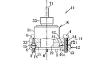
- the holder member 11 As shown in FIGS. 1 to 9, the holder member 11 includes an engagement male part forming member 14 that forms a tapered engagement male part 18, and the engagement male part forming member 14 is fixed by a plurality of bolts 15. And a holder body 16.
- the holder main body 16 includes a main body portion 31, a flat plate portion 32 to which the engaging male portion forming member 14 is fixed, a tool holding portion 33, and the like.
- An end mill T1 is fixed to the tool holding portion 33.
- the rotational shaft of the end mill T1 is connected to the rotational shaft of the rotational drive mechanism, but since it is a known technique, detailed description thereof is omitted.
- Four bolt mounting holes 34 into which four bolts 4 are inserted are formed at the four corners of the flat plate portion 32 of the holder body 16 in order to fix the holder member 11 to the mounting portion 2 of the turret 1.
- the engaging male part forming member 14 is formed from a square steel plate-like member in plan view.
- the engaging male part forming member 14 includes a positioning regulating surface 17 orthogonal to the axis 2a of the attachment part 2, and a tapered engagement male part 18 inclined so as to approach the axis 2a as it moves to the attachment part 2 side. And a through hole 19 communicating with the shaft hole 3 of the mounting portion 2.
- the positioning restriction surface 17 As shown in FIGS. 3 and 8, the positioning regulating surface 17 has an opening angle of about 4 at the bottom surface side corners of the engaging male portion forming member 14 and outside the tapered engaging male portion 18 in plan view. It is formed in a 45 ° arc shape. An insertion hole 21 through which the bolt 4 is inserted is formed at the center of each of the positioning regulating surfaces 17 (see FIG. 6). The positioning regulating surface 17 is brought into contact with the reference surface 37 to be positioned in the axial center 2a direction.
- a shallow annular groove 22 is formed on the inside in the radial direction of these positioning regulating surfaces 17.
- four bolt mounting holes into which the four bolts 15 are inserted and two knock pins for positioning the engaging male portion forming member 14 on the holder body 16 are inserted.
- a pin hole 24 is formed.
- the taper engaging male portion 18 includes four arc-shaped corner portions 26 and four side portions 27 whose cross section perpendicular to the axis 2a is convex outward. And is formed in a regular tetragonal shape (a pseudo regular square, a substantially regular square, or a shape close to a regular square).
- the taper engaging male portion 18 is formed so as to protrude integrally from the bottom surface of the engaging male portion forming member 14.
- the inclination angle of the taper engagement male portion 18 with respect to the axis 2a of the mounting portion 2 is preferably about 7 ° to 12 ° (see FIGS. 6 and 7).
- Each of the four side portions 27 of the taper engaging male portion 18 is formed in an arc shape with a minute curvature slightly bulging outward (see an imaginary line in FIG. 9).
- Each of the plurality of side portions 27 of the taper engaging male portion 18 has a relief recess 28 formed in the center thereof, and a pair of contact surfaces 29 chamfered on both sides of the relief recess 28. (See FIG. 9).
- the relief recess 28 of the taper engagement male part 18 is formed in a shallow groove shape along the axial direction on the taper surface of the engagement male part forming member 14.
- the relief recess 28 is formed in a region that is about a half of the side portion.
- the article positioning mechanism 10 approaches the mounting portion 2 in the radial direction and away from the axis 2a when the holder member 11 is fixed to the mounting portion 2 via the frame-shaped member 12 by four bolts 4 (fixing means).
- the taper engagement male part 18 is configured to be in close contact with the taper engagement female part 38 through elastic deformation of several ⁇ m of the outer peripheral side wall part 12a of the taper engagement female part 38 in the direction in which the taper engagement female part 38 is engaged. Yes.
- the taper engagement male part 18 is in close contact with the taper engagement female part 38, it is between the arcuate corner part 26 and the arcuate corner part 46, and between the relief recess 28 and the relief recess 48. A slight gap is formed (see FIG.
- the holder member 11 may be fixed to the frame-shaped member 12 with fixing means, such as a volt
- the operation and effect of the article positioning mechanism 10 will be described.
- the rotation phase around the axis 2a of the engagement male portion forming member 14 of the holder member 11 and the frame-shaped member 12 fixed to the attachment portion 2 is matched.
- the holder member 11 is engaged with the frame-shaped member 12, and the contact surface 29 of the taper engagement male portion 18 is lightly brought into contact with the contact surface 49 of the taper engagement female portion 38.
- a gap of about 0.03 to 0.15 ⁇ m is formed between the four positioning regulating surfaces 17 of the engaging male portion forming member 14 of the holder member 11 and the reference surface 37 of the frame-shaped member 12.
- the four bolts 4 are respectively inserted into the bolt mounting holes 34 of the holder member 11, and the insertion holes 21 of the engaging male portion forming member 14 and the insertion holes 43 of the frame-shaped member 12 are inserted, and the turret 1 is attached.
- the holder member 11 is fixed to the attachment portion 2 via the frame-shaped member 12 by screwing into the bolt hole 5 of the portion 2, the taper engagement in the radial direction away from the axis 2a and the direction approaching the attachment portion 2 is achieved.
- the contact surface 29 of the taper engagement male portion 18 is brought into close contact with the contact surface 49 of the taper engagement female portion 38 through elastic deformation of the outer peripheral side wall portion 12a of the mating female portion 38, and then positioning is performed.
- the regulating surface 17 comes into contact with the reference surface 37 to stop the elastic deformation and complete the positioning in the direction of the axis 2a.
- This elastic deformation includes radial elastic compression deformation of the upper peripheral wall 41 and elastic deformation in the direction of the axis 2a.
- the holder member 11 can be positioned with high accuracy in the direction of the axis 2 a of the mounting portion 2 by bringing the positioning regulating surface 17 of the holder member 11 into close contact with the reference surface 37 of the frame-shaped member 12.
- the holder member 11 can be positioned with high accuracy in the radial direction away from the shaft center 2a.
- the rotational phase around the axis 2a of the attachment portion 2 can be positioned with high accuracy, and the holder member 11 can be restrained from rotating around the axis 2a with respect to the attachment portion 2.
- the position restricting surface 17 or the reference surface 37 is not finely adjusted, and a movable member is not used for either the taper engagement male portion 18 or the taper engagement female portion 38. Two-sided restraint can be reliably achieved.
- the taper engaging female in the radial direction away from the shaft center 2a and the direction approaching the attachment portion 2 is obtained. Since the taper engagement male part 18 is brought into close contact with the taper engagement female part 38 through elastic deformation of the outer peripheral side wall part 12a of the part 38, the tool T1 is fixed by the article positioning mechanism 10.
- the member 11 can be positioned with high accuracy with respect to the mounting portion 2 and can be reliably rotationally restricted. Compared to positioning and rotation restraint using a small component such as a plurality of sets of keys and key grooves, the present application uses a square-shaped tapered engagement male part 18 and female part 38 for positioning.
- the rigidity of the article positioning mechanism 10 can be increased. Since one set of the taper engagement male part 18 and the taper engagement female part 38 are engaged with each other, the taper engagement male part can be smoothly engaged as compared with a combination of a plurality of sets of key grooves and keys. Since unnecessary contact with the female portions 18 and 38 can be avoided, the article positioning mechanism 10 having excellent durability can be obtained.
- Each of the plurality of side portions 27 and 47 of the taper engagement male portion 18 and the taper engagement female portion 38 is formed on the relief recesses 28 and 48 formed at the center thereof and on both sides of the relief recesses 28 and 48. Since the pair of contact surfaces 29 and 49 have a contact portion 29 and 49, when the taper engagement male portion 18 and the taper engagement female portion 38 are engaged in close contact, the pair of contact surfaces 29 and 49 The number is doubled, and the positioning accuracy in the direction orthogonal to the axis 2a of the mounting portion 2 and the rotation restraint force are improved.
- the side recesses 27 and 47 are provided with the relief recesses 28 and 48, the compressive stress of the pair of contact surfaces 29 and 49 is increased, so that the elastic deformation in the diameter increasing direction can be promoted and the adhesion can be improved. it can. Furthermore, since it is not necessary to polish the surfaces of the relief recesses 28 and 48, the polishing cost can be reduced.
- the regular polygonal shape of the taper engagement male part 18 and the taper engagement female part 38 is a regular tetragonal shape, and each of the plurality of side portions 27 and 47 of the taper engagement male part 18 and the taper engagement female part 38 is provided. Is formed in an arc shape that slightly bulges outward, so that when the taper engagement male portion 18 and the taper engagement female portion 38 are engaged in close contact, the side portion 27 of the taper engagement male portion 18 and The contact area with the side part 47 of the taper engagement female part 38 increases, the holder member 11 can be centered with high accuracy, and centripetalness can be improved.
- the holder member 11 includes an engagement male part forming member 14 that forms a taper engagement male part 18, and a holder body 16 to which the engagement male part forming member 14 is fixed by a plurality of bolts 15. Productivity is improved more than forming the taper engaging male portion 18 integrally with the main body 16, and the engaging male portion forming member 14 is fixed to the holder main body 16 with a plurality of bolts 15. It can be applied to the main body 16.
- the movable member of the machine device is a turret 1 of a turret lathe, and the turret 1 has a plurality of mounting portions 2 on the outer peripheral portion thereof, and the frame-shaped member 12 is provided on each of the mounting portions 2.
- the plurality of holder members 11 can be positioned with high accuracy and reliably restricted with respect to the plurality of attachment portions 2 of the turret 1 of the turret lathe.
- the frame-shaped member 12 Since the frame-shaped member 12 is positioned on the mounting portion 2 with a plurality of dowel pins 8 and fixed with a plurality of bolts 6, the frame-shaped member 12 can be repeatedly attached to and detached from the mounting portion 2, thereby improving reproducibility.
- the productivity is improved by forming the taper engaging female portion 38 integrally with the mounting portion 2.
- the holder member 11 has been described as an example, but the holder members 11A to 11C also have an engagement male portion forming member 14 that forms a taper engagement male portion 18 in the same manner as the holder member 11.
- the engaging male portion forming member 14 has holder bodies 16A to 16C having shapes corresponding to the tools T2, S1, and S2 fixed by a plurality of bolts 15. Also in the holder main bodies 16A to 16C, as with the holder main body 16, four bolt mounting holes 34 for fixing to the attachment portion 2 via four bolts 4 (fixing means) are formed.
- a plurality of slits 53 may be formed on the arcuate corner 46A of the taper engaging female portion 38A of the frame-shaped member 12A toward the radially outer side as an elastic deformation promoting portion.
- the radial direction and the attachment part separated from the axial center 2a of the outer peripheral side wall part 12a of the taper engagement female part 38A. Elastic deformation in the direction approaching 2 can be promoted.
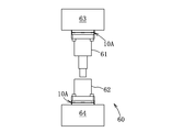
- the article positioning mechanism 10 is applied not only to the turret 1 of a turret lathe, but also to a forging machine 60 and other various molding machines like the article positioning mechanism 10A. can do.
- the article positioning mechanism 10A can position the punch 61 and the die 62 with respect to the mounting portion of the ram 63 and the machine base 64 (corresponding to the movable portion) with high accuracy and reliably restrain rotation.
- the shape of each of the plurality of side portions 27 and 47 need not be limited to an arc shape slightly bulging outward, and may be formed in a straight line shape.
- the shapes of the taper engagement male portion 18 and the taper engagement female portion 38 need not be limited to a regular tetragonal shape, but may be configured in various regular polygonal shapes such as a regular pentagonal shape and a regular hexagonal shape. May be.
- the engaging male part forming member 14 formed with the tapered engaging male part 18 is fixed to the holder body 16 and the frame-shaped member 12 formed with the taper engaging female part 38 is attached to the mounting part.
- the present invention is not particularly limited to this configuration.
- the engaging male portion forming member 14 may be fixed to the mounting portion 2 and the frame-shaped member 12 may be fixed to the holder main body 16. good.
- the positioning regulating surface 17 and the taper engagement male portion 18 are formed on the holder member 11, and the reference surface 37 and the taper engagement female portion 38 are formed on the frame-shaped member 12.
- the positioning regulating surface 17 and the taper engagement male portion 18 are formed on the frame-shaped member 12, and the reference surface 37 and the taper engagement female portion 38 are formed on the holder member 11. You may comprise. [7] In addition, various modifications can be made to the above-described embodiment without departing from the spirit of the present invention.
- the article positioning mechanism of the present invention can be used for various machine devices such as machine tools and robots, and other applications.
- Turret 2 Mounting portion 2a Axle 4 Bolt (fixing means) 8 Knock pins 10, 10A Article positioning mechanism 11 to 11C Holder member 12 Frame-shaped member 12a Outer peripheral side wall 14 Engaging male part forming member 16 to 16C Holder main body 17 Positioning regulating surface 18 Taper engaging male part 26 Arc-shaped corner 27 Side portion 28 Relief recess 29 Contact surface 37 Reference surface 38, 38A Taper engagement female portion 40a Annular space 46 Arc-shaped corner 47 Side portion 48 Relief recess 49 Contact surface
Landscapes
- Engineering & Computer Science (AREA)
- Mechanical Engineering (AREA)
- Jigs For Machine Tools (AREA)
- Cutting Tools, Boring Holders, And Turrets (AREA)
- Manipulator (AREA)
- Connection Of Plates (AREA)
Abstract
Description
(1)前記テーパ係合雄部の前記複数の辺部分の各々は、その中央部に形成された逃し凹部と、この逃し凹部の両側に形成された1対の接触面とを有し、前記テーパ係合雌部の前記複数の辺部分の各々は、その中央部に形成された逃し凹部と、この逃し凹部の両側に形成された1対の接触面とを有する。この構成によれば、テーパ係合雄部とテーパ係合雌部とが密着状に係合する際に、1対の接触面により密着箇所の数が2倍になり取付け部の軸心と直交する方向への位置決め精度と回転拘束力が向上する。また、辺部分に逃し凹部を設けたことにより1対の接触面の圧縮応力が増大するので径拡大方向への弾性変形を促進し密着性を向上することができる。さらに、逃し凹部の表面を研磨加工する必要がないので、研磨加工コストを低減できる。
このターレット1(機械装置の可動部材に相当する)は、ターレット式旋盤に取り付けられるものである。図1,2に示すように、ターレット1は、リング状に構成され、その外周部に複数の取付け部2を有している。これら取付け部2には、物品位置決め機構10の枠形部材12が夫々設けられている。取付け部2の軸心2a方向へ推進して削り込むドリルT1や軸心2a方向と直交する方向に穴を削り広げるエンドミルT2などの回転工具を保持する回転工具用ホルダ部材11,11Aや、バイトS1,S2などの旋削工具を保持する旋削工具用ホルダ部材11B,11Cなどの複数のホルダ部材11~11Cが、複数の取付け部2に枠形部材12を介して夫々固定されている。
図1~図3,図6,図7,図10,図11に示すように、枠形部材12は、平面視にて正方形の鋼製の板状部材から形成されている。枠形部材12は、開口40と、外周側壁部12a(図7参照)と、ホルダ部材11の位置決め用規制面17を受止めて軸心2a方向へ位置決めする基準面37と、ホルダ部材11のテーパ係合雄部18と同方向に傾斜したテーパ係合雌部38などを有している。枠形部材12は、取付け部2に2本のノックピン8で位置決めされて4本のボルト6で固定されている。枠形部材12の上面部には、その一辺が辺部分の約0.5~0.6倍の長さを有する開口40が形成されている。
図2,図10に示すように、基準面37は、枠形部材12の上面に構成されている。この基準面37には、4本のボルト4が挿通される4つの挿通孔43と、4本のボルト6が挿入されるボルト装着孔44と、2本のノックピン8が挿入される2つのピン孔45が形成されている。
図2,図3,図10,図11に示すように、テーパ係合雌部38は、軸心2aと直交方向の断面が外側へ凸の4つの円弧状角部46と4つの辺部分47とを有し、正四角形的形状(擬似正四角形又は略正四角形又は正四角形に近い形状)に形成されている。テーパ係合雌部38は、ターレット1の軸心1aの方へ移行する程軸心2aに近づくように傾斜状に形成されている。テーパ係合雌部38は、枠形部材12の開口40の上部周壁41に一体的に形成されている。テーパ係合雌部38の複数の辺部分47の各々が外側へ僅かに膨らんだ微小曲率の円弧状に形成されている。
図3,図6,図7に示すように、環状空間40aは、開口40の上部周壁41の奥側に形成されている。この環状空間40aは、テーパ係合雄部18がテーパ係合雌部38に密着状に係合する際の取付け部2へ接近する方向へ(奥方)の弾性変形を促進するためのものである。環状空間40aは、開口40の下部周壁42の内周側に形成されている。
図1~図9に示すように、ホルダ部材11は、テーパ係合雄部18を形成する係合雄部形成部材14と、この係合雄部形成部材14が複数のボルト15で固定されるホルダ本体16とを有している。
図1~図7に示すように、ホルダ本体16は、本体部31と、係合雄部形成部材14が固定される平板部32と、工具保持部33などから構成されている。この工具保持部33には、エンドミルT1が固定されている。エンドミルT1が回転駆動される場合、エンドミルT1の回転軸が回転駆動機構の回転軸に連結されるが、公知の技術であるため詳細な説明は省略する。このホルダ本体16の平板部32の四隅部には、ホルダ部材11をターレット1の取付け部2に固定するため、4本のボルト4が挿入される4つのボルト装着孔34が形成されている。
係合雄部形成部材14は、平面視にて正方形の鋼製の板状部材から形成されている。係合雄部形成部材14は、取付け部2の軸心2aと直交状の位置決め用規制面17と、取付け部2側へ移行する程軸心2aに近づくように傾斜したテーパ係合雄部18と、取付け部2の軸孔3に連通する貫通孔19とを有している。
図3,図8に示すように、位置決め用規制面17は、係合雄部形成部材14の底面側四隅部において、テーパ係合雄部18より外側の部分に平面視にて開角が約45°の円弧状に形成されている。これら位置決め用規制面17の各々の中心部には、ボルト4が挿通される挿通孔21が夫々形成されている(図6参照)。この位置決め用規制面17が、基準面37に当接して軸心2a方向位置の位置決めがなされる。
図3,図4,図6~図9に示すように、テーパ係合雄部18は、軸心2aと直交方向の断面が外側へ凸の4つの円弧状角部26と4つの辺部分27とを有し、正四角形的形状(擬似正四角形又は略正四角形又は正四角形に近い形状)に形成されている。テーパ係合雄部18は、係合雄部形成部材14の底面から一体的に突出するように形成されている。テーパ係合雄部18の取付け部2の軸心2aに対する傾斜角は、7°~12°程度が望ましい(図6,図7参照)。テーパ係合雄部18の4つの辺部分27の各々は、外側へ僅かに膨らんだ微小曲率の円弧状に形成されている(図9の仮想線参照)。
先ず、ターレット1の取付け部2にホルダ部材11を固定するため、ホルダ部材11の係合雄部形成部材14と取付け部2に固定された枠形部材12の軸心2a回りの回転位相を一致させた状態で、ホルダ部材11を枠形部材12に係合させ、テーパ係合雌部38の接触面49にテーパ係合雄部18の接触面29を軽く当接させる。尚、このときホルダ部材11の係合雄部形成部材14の4つの位置決め用規制面17と枠形部材12の基準面37との間には約0.03~0.15μmの隙間が形成される。
[1]図12に示すように、枠形部材12Aのテーパ係合雌部38Aの円弧状角部46Aに弾性変形促進部として径方向外側に向けて複数のスリット53を形成しても良い。この構成によると、テーパ係合雄部18とテーパ係合雌部38Aが密着状に係合するとき、テーパ係合雌部38Aの外周側壁部12aの軸心2aから離隔する径方向と取付け部2へ接近する方向への弾性変形を促進することができる。
[2]図13に示すように、物品位置決め機構10は、ターレット式旋盤のターレット1に適用されるだけでなく、物品位置決め機構10Aのように圧造成形機60やその他種々の成形機にも適用することができる。この場合は、物品位置決め機構10Aにより、パンチ61やダイ62をラム63や機台64(可動部に相当する)の取付け部に対して夫々高精度に位置決めし且つ確実に回転拘束することができる。
[3]複数の辺部分27,47の各々の形状は、外側へ僅かに膨らんだ円弧状に限定する必要はなく、直線状に形成しても良い。
[4]テーパ係合雄部18とテーパ係合雌部38の形状は正四角形的形状に限定する必要はなく、正五角形的形状や正六角形的形状など種々の正多角形的形状に構成しても良い。
[5]本実施例では、テーパ係合雄部18が形成された係合雄部形成部材14をホルダ本体16に固定し、テーパ係合雌部38が形成された枠形部材12を取付け部2に固定しているが、特にこの構成に限定する必要はなく、係合雄部形成部材14を取付け部2に固定し、枠形部材12をホルダ本体16に固定するように構成しても良い。
[6]本実施例では、ホルダ部材11に位置決め用規制面17とテーパ係合雄部18とを形成し、枠形部材12に基準面37とテーパ係合雌部38とを形成しているが、この構成とは逆に、枠形部材12に位置決め用規制面17とテーパ係合雄部18とを形成し、ホルダ部材11に基準面37とテーパ係合雌部38とを形成するように構成しても良い。
[7]その他、本発明の趣旨を逸脱しない範囲において前記実施例に種々の変形を付加した形態で実施することができる。
2 取付け部
2a 軸心
4 ボルト(固定手段)
8 ノックピン
10,10A 物品位置決め機構
11~11C ホルダ部材
12 枠形部材
12a 外周側壁部
14 係合雄部形成部材
16~16C ホルダ本体
17 位置決め用規制面
18 テーパ係合雄部
26 円弧状角部
27 辺部分
28 逃し凹部
29 接触面
37 基準面
38,38A テーパ係合雌部
40a 環状空間
46 円弧状角部
47 辺部分
48 逃し凹部
49 接触面
Claims (7)
- 機械装置の可動部材の取付け部に部品又は工具からなる物品を位置決めすると共に回転拘束するための物品位置決め機構において、
前記物品が固定されたホルダ部材と前記取付け部に固定された枠形部材とを備え、
前記ホルダ部材は、前記取付け部の軸心と直交状の位置決め用規制面と、前記軸心と直交方向の断面が外側へ凸の複数の円弧状角部と複数の辺部分とを有する正多角形的形状に形成され且つ前記取付け部側へ移行する程前記軸心に近づくように傾斜したテーパ係合雄部とを有し、
前記枠形部材は、前記位置決め用規制面を受止めて前記軸心方向へ位置決めする基準面と、前記軸心と直交方向の断面が外側へ凸の複数の円弧状角部と複数の辺部分とを有する正多角形的形状に形成され且つ前記テーパ係合雄部と同方向に傾斜したテーパ係合雌部とを有し、
前記ホルダ部材を前記取付け部又は枠形部材に固定手段により固定するとき、前記軸心から離隔する径方向と前記取付け部へ接近する方向への前記テーパ係合雌部の外周側壁部の弾性変形を介して、前記テーパ係合雄部がテーパ係合雌部に密着状に係合するように構成したことを特徴とする物品位置決め機構。 - 前記テーパ係合雄部の前記複数の辺部分の各々は、その中央部に形成された逃し凹部と、この逃し凹部の両側に形成された1対の接触面とを有し、
前記テーパ係合雌部の前記複数の辺部分の各々は、その中央部に形成された逃し凹部と、この逃し凹部の両側に形成された1対の接触面とを有することを特徴とする請求項1に記載の物品位置決め機構。 - 前記テーパ係合雄部と前記テーパ係合雌部の正多角形的形状が正四角形的形状であり、
前記テーパ係合雄部の複数の辺部分の各々が外側へ僅かに膨らんだ円弧状に形成され、前記テーパ係合雌部の複数の辺部分の各々が外側へ僅かに膨らんだ円弧状に形成されたことを特徴とする請求項1又は2に記載の物品位置決め機構。 - 前記テーパ係合雌部の外周側壁部の奥側には、前記テーパ係合雄部が前記テーパ係合雌部に密着状に係合する際の前記取付け部へ接近する方向への弾性変形を促進するための環状空間が形成されたことを特徴とする請求項3に記載の物品位置決め機構。
- 前記ホルダ部材は、前記テーパ係合雄部を形成する係合雄部形成部材と、この係合雄部形成部材が複数のボルトで固定されるホルダ本体とを有することを特徴とする請求項3に記載の物品位置決め機構。
- 前記機械装置の可動部材は、ターレット式旋盤のターレットであり、このターレットはその外周部に複数の前記取付け部を有し、これら取付け部に前記枠形部材が夫々設けられたことを特徴とする請求項1に記載の物品位置決め機構。
- 前記枠形部材は、前記取付け部に複数のノックピンで位置決めされて複数のボルトで固定されたことを特徴とする請求項6に記載の物品位置決め機構。
Priority Applications (3)
| Application Number | Priority Date | Filing Date | Title |
|---|---|---|---|
| EP10797043.6A EP2452769A4 (en) | 2009-07-08 | 2010-06-29 | ARTICLE POSITIONING MECHANISM |
| CN2010800271342A CN102470450A (zh) | 2009-07-08 | 2010-06-29 | 物品定位机构 |
| US13/261,119 US9061387B2 (en) | 2009-07-08 | 2010-06-29 | Article positioning mechanism |
Applications Claiming Priority (2)
| Application Number | Priority Date | Filing Date | Title |
|---|---|---|---|
| JP2009162192A JP5385709B2 (ja) | 2009-07-08 | 2009-07-08 | 物品位置決め機構 |
| JP2009-162192 | 2009-07-08 |
Publications (1)
| Publication Number | Publication Date |
|---|---|
| WO2011004732A1 true WO2011004732A1 (ja) | 2011-01-13 |
Family
ID=43429154
Family Applications (1)
| Application Number | Title | Priority Date | Filing Date |
|---|---|---|---|
| PCT/JP2010/061029 Ceased WO2011004732A1 (ja) | 2009-07-08 | 2010-06-29 | 物品位置決め機構 |
Country Status (7)
| Country | Link |
|---|---|
| US (1) | US9061387B2 (ja) |
| EP (1) | EP2452769A4 (ja) |
| JP (1) | JP5385709B2 (ja) |
| KR (1) | KR20120034221A (ja) |
| CN (1) | CN102470450A (ja) |
| TW (1) | TW201105441A (ja) |
| WO (1) | WO2011004732A1 (ja) |
Cited By (2)
| Publication number | Priority date | Publication date | Assignee | Title |
|---|---|---|---|---|
| CN107199432A (zh) * | 2017-07-25 | 2017-09-26 | 湖北汽车工业学院 | 宝塔形环焊工装 |
| CN111775086A (zh) * | 2020-07-30 | 2020-10-16 | 湖州鸿盈机械有限公司 | 一种基于自动化机械用的管件夹紧装置 |
Families Citing this family (6)
| Publication number | Priority date | Publication date | Assignee | Title |
|---|---|---|---|---|
| CN103158022A (zh) * | 2012-11-20 | 2013-06-19 | 苏州工业园区高登威科技有限公司 | 工件定位装置 |
| CN106271800A (zh) * | 2016-08-30 | 2017-01-04 | 昆山宝锦激光拼焊有限公司 | 一种上料小车定位装置 |
| CN110605589B (zh) * | 2018-06-15 | 2021-09-03 | 捷普电子(新加坡)公司 | 定位治具及其与多轴加工机台的组合和定位精度检测方法 |
| KR102585462B1 (ko) * | 2019-02-22 | 2023-10-10 | 주식회사 디엔솔루션즈 | 공작 기계의 틸팅 테이블 위치 결정 장치 |
| JP2023104716A (ja) * | 2022-01-18 | 2023-07-28 | エヌティーツール株式会社 | 工具ホルダ |
| US20260084254A1 (en) * | 2024-09-23 | 2026-03-26 | Jamey Hankins | Cnc lathe live radial tool spacer |
Citations (4)
| Publication number | Priority date | Publication date | Assignee | Title |
|---|---|---|---|---|
| JPH0578406U (ja) * | 1992-03-30 | 1993-10-26 | 本田技研工業株式会社 | ツールホルダの固定装置 |
| JP2000246521A (ja) * | 1999-03-03 | 2000-09-12 | Big Alpha Kk | 工具ホルダー取付装置 |
| WO2001076814A1 (en) * | 2000-04-10 | 2001-10-18 | Pascal Kabushiki Kaisha | Tool holder |
| JP2006167862A (ja) | 2004-12-16 | 2006-06-29 | Mori Seiki Co Ltd | 刃物台 |
Family Cites Families (14)
| Publication number | Priority date | Publication date | Assignee | Title |
|---|---|---|---|---|
| US3711106A (en) * | 1971-09-03 | 1973-01-16 | Budd Co | Centering device for a chuck |
| US3898714A (en) * | 1973-10-09 | 1975-08-12 | James D Mcfadden | Pipe alignment clamp |
| US4753555A (en) * | 1986-12-31 | 1988-06-28 | Douglas Thompson | Apparatus and method for the drilling and inspecting of holes |
| JP3115919B2 (ja) | 1991-09-20 | 2000-12-11 | 信越化学工業株式会社 | 塩化ビニル系重合体の製造方法 |
| EP0693984B1 (de) * | 1993-04-14 | 1997-08-27 | Zettl Gmbh Cnc Präzisions- Und Sonderwerkzeuge | Schneidwerkzeug |
| DE19548151A1 (de) * | 1995-12-22 | 1997-07-17 | Index Werke Kg Hahn & Tessky | Werkzeugfixierung |
| US5822841A (en) * | 1996-12-17 | 1998-10-20 | United Technologies Corporation | IBR fixture |
| DE19940330C2 (de) * | 1999-08-25 | 2001-06-13 | Esa Eppinger Gmbh | Werkzeugspanneinrichtung |
| JP4762448B2 (ja) * | 2001-07-24 | 2011-08-31 | パスカルエンジニアリング株式会社 | ワークパレット位置決め固定装置 |
| JP5064622B2 (ja) * | 2001-09-21 | 2012-10-31 | パスカルエンジニアリング株式会社 | クランプ装置 |
| DE20321518U1 (de) * | 2003-09-11 | 2007-09-20 | Index-Werke Gmbh & Co. Kg Hahn & Tessky | Werkzeugmaschine und hierzu vorgesehener Werkzeugträger |
| CN1890051B (zh) * | 2004-05-19 | 2012-05-23 | 帕斯卡工程株式会社 | 定位固定装置及定位装置 |
| ATE402785T1 (de) * | 2005-03-24 | 2008-08-15 | 3R Syst Int Ab | Kupplungsvorrichtung mit elastischen bereichen zur x-y-ausrichtung |
| JP5627664B2 (ja) * | 2010-02-23 | 2014-11-19 | パスカルエンジニアリング株式会社 | ワークパレット位置決め固定装置 |
-
2009
- 2009-07-08 JP JP2009162192A patent/JP5385709B2/ja not_active Expired - Fee Related
-
2010
- 2010-06-29 EP EP10797043.6A patent/EP2452769A4/en not_active Withdrawn
- 2010-06-29 US US13/261,119 patent/US9061387B2/en not_active Expired - Fee Related
- 2010-06-29 WO PCT/JP2010/061029 patent/WO2011004732A1/ja not_active Ceased
- 2010-06-29 CN CN2010800271342A patent/CN102470450A/zh active Pending
- 2010-06-29 KR KR20127002832A patent/KR20120034221A/ko not_active Withdrawn
- 2010-07-08 TW TW99122458A patent/TW201105441A/zh unknown
Patent Citations (4)
| Publication number | Priority date | Publication date | Assignee | Title |
|---|---|---|---|---|
| JPH0578406U (ja) * | 1992-03-30 | 1993-10-26 | 本田技研工業株式会社 | ツールホルダの固定装置 |
| JP2000246521A (ja) * | 1999-03-03 | 2000-09-12 | Big Alpha Kk | 工具ホルダー取付装置 |
| WO2001076814A1 (en) * | 2000-04-10 | 2001-10-18 | Pascal Kabushiki Kaisha | Tool holder |
| JP2006167862A (ja) | 2004-12-16 | 2006-06-29 | Mori Seiki Co Ltd | 刃物台 |
Non-Patent Citations (1)
| Title |
|---|
| See also references of EP2452769A4 * |
Cited By (3)
| Publication number | Priority date | Publication date | Assignee | Title |
|---|---|---|---|---|
| CN107199432A (zh) * | 2017-07-25 | 2017-09-26 | 湖北汽车工业学院 | 宝塔形环焊工装 |
| CN107199432B (zh) * | 2017-07-25 | 2023-01-20 | 湖北汽车工业学院 | 宝塔形环焊工装 |
| CN111775086A (zh) * | 2020-07-30 | 2020-10-16 | 湖州鸿盈机械有限公司 | 一种基于自动化机械用的管件夹紧装置 |
Also Published As
| Publication number | Publication date |
|---|---|
| JP2011016192A (ja) | 2011-01-27 |
| EP2452769A4 (en) | 2013-05-01 |
| JP5385709B2 (ja) | 2014-01-08 |
| TW201105441A (en) | 2011-02-16 |
| US9061387B2 (en) | 2015-06-23 |
| EP2452769A1 (en) | 2012-05-16 |
| US20120112398A1 (en) | 2012-05-10 |
| KR20120034221A (ko) | 2012-04-10 |
| CN102470450A (zh) | 2012-05-23 |
Similar Documents
| Publication | Publication Date | Title |
|---|---|---|
| JP5385709B2 (ja) | 物品位置決め機構 | |
| JP5627664B2 (ja) | ワークパレット位置決め固定装置 | |
| JP5572449B2 (ja) | 物体位置決め固定装置 | |
| US9919366B2 (en) | Cutting insert and a tool holder with a seat for cutting insert | |
| EP1992435B1 (en) | Tool holder positioning device | |
| JP5062329B2 (ja) | ロータリバイト | |
| JP5964640B2 (ja) | 物体位置決め固定装置 | |
| JP5946706B2 (ja) | 物体位置決め固定装置 | |
| JP6530142B1 (ja) | インサート及びボディ | |
| JP5996306B2 (ja) | 物体位置決め固定装置 | |
| EP3285947B1 (en) | Chuck arrangement | |
| JP2012254514A (ja) | 切削インサートのクランプ機構、ホルダ、切削インサート及び切削工具 | |
| JP2015150649A (ja) | チャック装置 | |
| JP7023941B2 (ja) | チャック機構 | |
| JP3227397U (ja) | 強固に組立てられたカッター保持アセンブリ | |
| JP5480047B2 (ja) | 位置決め体及び工作機械 | |
| JP5694267B2 (ja) | チャック | |
| KR20110025467A (ko) | 전단각을 가지는 절삭 인서트 팁 | |
| KR20030046913A (ko) | 절삭공구용 결합장치 | |
| JP2001353610A (ja) | ピンミラーカッタの取付機構 | |
| JP2005186208A (ja) | 機械加工治具及びそれを用いたワーク加工方法 | |
| JP2007210013A (ja) | 金属缶製造装置 |
Legal Events
| Date | Code | Title | Description |
|---|---|---|---|
| WWE | Wipo information: entry into national phase |
Ref document number: 201080027134.2 Country of ref document: CN |
|
| 121 | Ep: the epo has been informed by wipo that ep was designated in this application |
Ref document number: 10797043 Country of ref document: EP Kind code of ref document: A1 |
|
| WWE | Wipo information: entry into national phase |
Ref document number: 13261119 Country of ref document: US |
|
| NENP | Non-entry into the national phase |
Ref country code: DE |
|
| WWE | Wipo information: entry into national phase |
Ref document number: 2010797043 Country of ref document: EP |
|
| ENP | Entry into the national phase |
Ref document number: 20127002832 Country of ref document: KR Kind code of ref document: A |