WO2011007535A1 - 電池接続部材とそれを用いた電池モジュール - Google Patents
電池接続部材とそれを用いた電池モジュール Download PDFInfo
- Publication number
- WO2011007535A1 WO2011007535A1 PCT/JP2010/004488 JP2010004488W WO2011007535A1 WO 2011007535 A1 WO2011007535 A1 WO 2011007535A1 JP 2010004488 W JP2010004488 W JP 2010004488W WO 2011007535 A1 WO2011007535 A1 WO 2011007535A1
- Authority
- WO
- WIPO (PCT)
- Prior art keywords
- battery
- connection terminal
- fuse
- battery module
- batteries
- Prior art date
- Legal status (The legal status is an assumption and is not a legal conclusion. Google has not performed a legal analysis and makes no representation as to the accuracy of the status listed.)
- Ceased
Links
Images


Classifications
-
- H—ELECTRICITY
- H01—ELECTRIC ELEMENTS
- H01M—PROCESSES OR MEANS, e.g. BATTERIES, FOR THE DIRECT CONVERSION OF CHEMICAL ENERGY INTO ELECTRICAL ENERGY
- H01M50/00—Constructional details or processes of manufacture of the non-active parts of electrochemical cells other than fuel cells, e.g. hybrid cells
- H01M50/50—Current conducting connections for cells or batteries
-
- H—ELECTRICITY
- H01—ELECTRIC ELEMENTS
- H01M—PROCESSES OR MEANS, e.g. BATTERIES, FOR THE DIRECT CONVERSION OF CHEMICAL ENERGY INTO ELECTRICAL ENERGY
- H01M10/00—Secondary cells; Manufacture thereof
- H01M10/05—Accumulators with non-aqueous electrolyte
- H01M10/052—Li-accumulators
- H01M10/0525—Rocking-chair batteries, i.e. batteries with lithium insertion or intercalation in both electrodes; Lithium-ion batteries
-
- H—ELECTRICITY
- H01—ELECTRIC ELEMENTS
- H01M—PROCESSES OR MEANS, e.g. BATTERIES, FOR THE DIRECT CONVERSION OF CHEMICAL ENERGY INTO ELECTRICAL ENERGY
- H01M50/00—Constructional details or processes of manufacture of the non-active parts of electrochemical cells other than fuel cells, e.g. hybrid cells
- H01M50/20—Mountings; Secondary casings or frames; Racks, modules or packs; Suspension devices; Shock absorbers; Transport or carrying devices; Holders
- H01M50/204—Racks, modules or packs for multiple batteries or multiple cells
- H01M50/207—Racks, modules or packs for multiple batteries or multiple cells characterised by their shape
- H01M50/213—Racks, modules or packs for multiple batteries or multiple cells characterised by their shape adapted for cells having curved cross-section, e.g. round or elliptic
-
- H—ELECTRICITY
- H01—ELECTRIC ELEMENTS
- H01M—PROCESSES OR MEANS, e.g. BATTERIES, FOR THE DIRECT CONVERSION OF CHEMICAL ENERGY INTO ELECTRICAL ENERGY
- H01M50/00—Constructional details or processes of manufacture of the non-active parts of electrochemical cells other than fuel cells, e.g. hybrid cells
- H01M50/30—Arrangements for facilitating escape of gases
- H01M50/35—Gas exhaust passages comprising elongated, tortuous or labyrinth-shaped exhaust passages
- H01M50/367—Internal gas exhaust passages forming part of the battery cover or case; Double cover vent systems
-
- H—ELECTRICITY
- H01—ELECTRIC ELEMENTS
- H01M—PROCESSES OR MEANS, e.g. BATTERIES, FOR THE DIRECT CONVERSION OF CHEMICAL ENERGY INTO ELECTRICAL ENERGY
- H01M50/00—Constructional details or processes of manufacture of the non-active parts of electrochemical cells other than fuel cells, e.g. hybrid cells
- H01M50/50—Current conducting connections for cells or batteries
- H01M50/502—Interconnectors for connecting terminals of adjacent batteries; Interconnectors for connecting cells outside a battery casing
- H01M50/509—Interconnectors for connecting terminals of adjacent batteries; Interconnectors for connecting cells outside a battery casing characterised by the type of connection, e.g. mixed connections
- H01M50/512—Connection only in parallel
-
- H—ELECTRICITY
- H01—ELECTRIC ELEMENTS
- H01M—PROCESSES OR MEANS, e.g. BATTERIES, FOR THE DIRECT CONVERSION OF CHEMICAL ENERGY INTO ELECTRICAL ENERGY
- H01M50/00—Constructional details or processes of manufacture of the non-active parts of electrochemical cells other than fuel cells, e.g. hybrid cells
- H01M50/50—Current conducting connections for cells or batteries
- H01M50/572—Means for preventing undesired use or discharge
- H01M50/574—Devices or arrangements for the interruption of current
- H01M50/581—Devices or arrangements for the interruption of current in response to temperature
-
- H—ELECTRICITY
- H01—ELECTRIC ELEMENTS
- H01M—PROCESSES OR MEANS, e.g. BATTERIES, FOR THE DIRECT CONVERSION OF CHEMICAL ENERGY INTO ELECTRICAL ENERGY
- H01M50/00—Constructional details or processes of manufacture of the non-active parts of electrochemical cells other than fuel cells, e.g. hybrid cells
- H01M50/50—Current conducting connections for cells or batteries
- H01M50/572—Means for preventing undesired use or discharge
- H01M50/574—Devices or arrangements for the interruption of current
- H01M50/583—Devices or arrangements for the interruption of current in response to current, e.g. fuses
-
- H—ELECTRICITY
- H01—ELECTRIC ELEMENTS
- H01M—PROCESSES OR MEANS, e.g. BATTERIES, FOR THE DIRECT CONVERSION OF CHEMICAL ENERGY INTO ELECTRICAL ENERGY
- H01M2200/00—Safety devices for primary or secondary batteries
-
- H—ELECTRICITY
- H01—ELECTRIC ELEMENTS
- H01M—PROCESSES OR MEANS, e.g. BATTERIES, FOR THE DIRECT CONVERSION OF CHEMICAL ENERGY INTO ELECTRICAL ENERGY
- H01M2200/00—Safety devices for primary or secondary batteries
- H01M2200/10—Temperature sensitive devices
- H01M2200/103—Fuse
-
- Y—GENERAL TAGGING OF NEW TECHNOLOGICAL DEVELOPMENTS; GENERAL TAGGING OF CROSS-SECTIONAL TECHNOLOGIES SPANNING OVER SEVERAL SECTIONS OF THE IPC; TECHNICAL SUBJECTS COVERED BY FORMER USPC CROSS-REFERENCE ART COLLECTIONS [XRACs] AND DIGESTS
- Y02—TECHNOLOGIES OR APPLICATIONS FOR MITIGATION OR ADAPTATION AGAINST CLIMATE CHANGE
- Y02E—REDUCTION OF GREENHOUSE GAS [GHG] EMISSIONS, RELATED TO ENERGY GENERATION, TRANSMISSION OR DISTRIBUTION
- Y02E60/00—Enabling technologies; Technologies with a potential or indirect contribution to GHG emissions mitigation
- Y02E60/10—Energy storage using batteries
-
- Y—GENERAL TAGGING OF NEW TECHNOLOGICAL DEVELOPMENTS; GENERAL TAGGING OF CROSS-SECTIONAL TECHNOLOGIES SPANNING OVER SEVERAL SECTIONS OF THE IPC; TECHNICAL SUBJECTS COVERED BY FORMER USPC CROSS-REFERENCE ART COLLECTIONS [XRACs] AND DIGESTS
- Y02—TECHNOLOGIES OR APPLICATIONS FOR MITIGATION OR ADAPTATION AGAINST CLIMATE CHANGE
- Y02T—CLIMATE CHANGE MITIGATION TECHNOLOGIES RELATED TO TRANSPORTATION
- Y02T10/00—Road transport of goods or passengers
- Y02T10/60—Other road transportation technologies with climate change mitigation effect
- Y02T10/70—Energy storage systems for electromobility, e.g. batteries
Definitions
- the present invention relates to a battery connecting member for connecting a plurality of batteries in parallel and a battery module using the same.
- lithium ion secondary battery is characterized by high electromotive force and high energy density while being lightweight. For this reason, there is an increasing demand for power sources for driving various types of portable electronic devices such as mobile phones, digital cameras, video cameras, laptop computers, and mobile communication devices.
- This battery module is composed of two or more batteries in order to obtain a desired voltage and capacity.
- the safety of the battery modules that are aggregates of them is more important than the safety of the batteries themselves. That is, the battery may not play the role of a battery due to overcharge, overdischarge, internal short circuit, or external short circuit.
- the internal pressure of a battery is increased by gas generated by overcharge, overdischarge, internal short circuit, or external short circuit, and in some cases, the battery outer case may burst. Therefore, in a battery module in which a plurality of batteries are integrated, it is important to prevent deterioration of the performance of the entire battery module due to an abnormality of one battery.
- a battery module in which a temperature-sensitive element that disconnects a connection when a current greater than a specified value flows in a connection portion between the batteries (for example, Patent Document 1). Also disclosed is a battery module in which a fuse is formed between batteries connected in series by metal wiring printed on an insulating substrate (for example, Patent Document 2).
- Patent Document 1 and Patent Document 2 a temperature-sensitive element or a fuse is provided between a plurality of batteries connected in series, and if any one of the batteries is abnormal, immediately In addition, the function of the entire battery module is stopped. Therefore, there is a problem that a battery having no problem is wasted. In addition, since the temperature sensitive element and the fuse itself are large, there is a problem that it is difficult to reduce the size of the battery module because it takes up space when assembled in the battery module.
- the present invention solves the above-described problem, and in a battery module in which a plurality of batteries are connected in parallel, a battery that can prevent the performance of the entire battery module from being greatly deteriorated by a battery in which a defect such as an internal short circuit has occurred. It is an object to provide a connecting member and a battery module using the connecting member.
- the battery connection member according to the present invention is a battery connection member that connects a plurality of batteries in parallel, and includes a plurality of main conduction path portions, and a plurality of individual connections between the main conduction path portions and one electrode of the plurality of batteries.
- the connection terminal has a fuse portion that is blown when a current of a predetermined value or more flows. And when a some battery is connected in parallel with the battery connection member which concerns on this invention, a fuse part is arrange
- the fuse part is disposed in the space between the battery and the main conductive path part, so that the Joule heat generated when an overcurrent flows through the fuse part. Heat dissipation can be suppressed. Therefore, it becomes easy to design a fuse part that is blown by a temperature rise due to Joule heat, and design variations can be reduced. Furthermore, the thermal effect given to another battery and a connection member can also be suppressed by the temperature rise by Joule heat.
- the battery module according to the present invention is a battery module in which a plurality of batteries are housed in a housing portion, and the plurality of batteries are connected in parallel by a battery connection member, and the battery connection member is a main conductive path. And a plurality of connection terminals that individually connect the main conductive path part and one of the plurality of battery poles, and the connection terminal includes a fuse part that is blown when a current of a predetermined value or more flows.
- the fuse portion has a configuration in which the fuse portion is disposed in the space between the battery and the main conductive path portion.
- the present invention even when there is a defective battery such as an internal short circuit, it is possible to realize a battery connection member capable of cutting only the connection with the defective battery and a battery module using the same.
- FIG. 1 is a cross-sectional view of a battery constituting the battery module according to Embodiment 1 of the present invention.
- (b) Side view of external appearance of battery module according to Embodiment 1 of the present invention 1 is an exploded perspective view of a battery module according to Embodiment 1 of the present invention.
- 3 is a vertical cross-sectional view of the battery module according to Embodiment 1 of the present invention, taken along the line A-A ′ of FIG. 1 is a cross-sectional perspective view of a main part of a battery module according to Embodiment 1 of the present invention.
- FIG. 3 is a longitudinal sectional view of the A-A ′ plane in FIG. 3 for explaining the operation when a defective battery is generated in the battery module according to Embodiment 1 of the present invention.
- the longitudinal cross-sectional view of the battery module in other embodiment of this invention The top view of the battery module in
- a battery connection member is a battery connection member that connects a plurality of batteries in parallel, and each of the main conductive path part and the main conductive path part and one electrode of the plurality of batteries is individually connected.
- the connection terminal has a fuse portion that is blown when a current of a predetermined value or more flows. And when a some battery is connected in parallel by the battery connection member, a fuse part is arrange
- the fuse portion is integrally formed of the same member as the connection terminal.
- the connection terminal is integrally formed of the same member as the main conductive path portion.
- the cross-sectional area at the fuse portion of the connection terminal may be made smaller than the cross-sectional area at other portions of the connection terminal.
- the thickness of the fuse portion of the connection terminal may be made thinner than the thickness of other portions of the connection terminal.
- the resistance of the member in the fuse portion of the connection terminal may be larger than the resistance of the member in the other part of the connection terminal.
- you may comprise a fuse part with a chip fuse.
- the battery module in one embodiment of the present invention is a battery module in which a plurality of batteries are stored in a storage unit, and the plurality of batteries are connected in parallel by a battery connection member, and the battery connection member is a main conductive member.
- a fuse part that has a path part, a plurality of connection terminals that individually connect the main conductive path part and one pole of the plurality of batteries, and the connection terminal is blown when a current of a predetermined value or more flows;
- the fuse portion is disposed in the space between the battery and the main conductive path portion.
- the fuse portion is integrally formed of the same member as the connection terminal. Furthermore, it is preferable that the connection terminal is integrally formed of the same member as the main conductive path portion.
- the cross-sectional area of the fuse portion of the connection terminal is smaller than the cross-sectional area of other portions of the connection terminal.
- the connection terminal has a uniform width, and the thickness of the fuse portion of the connection terminal may be made thinner than the thickness of other portions of the connection terminal.
- the resistance of the member in the fuse portion of the connection terminal may be larger than the resistance of the member in the other part of the connection terminal.
- the fuse portion may be constituted by a chip fuse.
- FIG. 1 is a cross-sectional view of a battery constituting the battery module according to Embodiment 1 of the present invention.
- a cylindrical battery is formed by winding a positive electrode 1 having an aluminum positive electrode lead 8 and a negative electrode 2 having, for example, a copper negative electrode lead 9 at one end via a separator 3.
- the electrode group 4 is provided.
- the insulating plates 10a and 10b are mounted on the upper and lower sides of the electrode group 4 and inserted into the battery case 5, the other end of the positive electrode lead 8 is used as the sealing plate 6, and the other end of the negative electrode lead 9 is used as the battery case 5. Weld to the bottom.
- a non-aqueous electrolyte (not shown) that conducts lithium ions is injected into the battery case 5, and the open portion of the battery case 5 is connected to the current blocking member 18 such as the positive electrode cap 16 and the PTC element via the gasket 7.
- the sealing plate 6 is caulked and sealed.
- the positive electrode cap 16 is provided with an exhaust hole 17 for extracting gas generated by opening a vent mechanism 19 such as a safety valve due to a failure of the electrode group 4.
- the positive electrode 1 is comprised from the positive electrode collector 1a and the positive electrode layer 1b containing a positive electrode active material.
- the positive electrode layer 1b contains, for example, lithium-containing composite oxide such as LiCoO 2 , LiNiO 2 , Li 2 MnO 4 , or a mixture or composite compound thereof as a positive electrode active material.
- the positive electrode layer 1b further includes a conductive agent and a binder.
- the conductive agent include natural graphite and artificial graphite graphite, acetylene black, ketjen black, channel black, furnace black, lamp black, thermal black, and other carbon blacks. Including tetrafluoroethylene, polyethylene, polypropylene, aramid resin, polyamide, polyimide and the like.
- the positive electrode current collector 1a used for the positive electrode aluminum (Al), carbon (C), conductive resin, or the like can be used.
- non-aqueous electrolyte an electrolyte solution in which a solute is dissolved in an organic solvent, or a so-called polymer electrolyte layer containing these and non-fluidized with a polymer can be applied.
- solute of the non-aqueous electrolyte LiPF 6 , LiBF 4 , LiClO 4 , LiAlCl 4 , LiSbF 6 , LiSCN, LiCF 3 SO 3 , LiN (CF 3 CO 2 ), LiN (CF 3 SO 2 ) 2, etc. should be used. Can do.
- organic solvent for example, ethylene carbonate (EC), propylene carbonate, butylene carbonate, vinylene carbonate, dimethyl carbonate (DMC), diethyl carbonate, ethyl methyl carbonate (EMC) and the like can be used.
- EC ethylene carbonate
- DMC dimethyl carbonate
- EMC ethyl methyl carbonate
- the negative electrode current collector 11 of the negative electrode 2 is made of a metal foil such as stainless steel, nickel, copper, or titanium, or a thin film of carbon or conductive resin.
- the negative electrode layer 15 of the negative electrode 2 has a theoretical capacity density of 833 mAh / cm 3 for reversibly occluding and releasing lithium ions such as carbon materials such as graphite, silicon (Si), tin (Sn), and the like. More negative electrode active materials can be used.
- FIG. 2 a), 2 (b), and 3.
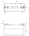
- FIG. 2A is an external top view of the battery module 100 according to Embodiment 1 of the present invention
- FIG. 2B is an external lateral view of the battery module 100 according to Embodiment 1 of the present invention
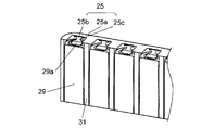
- FIG. 3 is an exploded perspective view of the battery module according to Embodiment 1 of the present invention.
- the battery module 100 includes a housing portion 30 made of an insulating resin material such as polycarbonate resin, and a lid 20 that fits into the housing portion 30.
- the storage unit 30 has an open end on one surface (the upper surface in FIG. 3).
- the lid 20 is provided so as to cover the opening end of the storage unit 30.
- a partition wall 31 is provided in the space formed by the storage unit 30 and the lid 20.
- a battery 29 is inserted into each of the storage portions 30 separated by the partition walls 31.
- the partition wall 31 is preferably a metal or a high heat conduction member instead of a metal in order to improve heat conduction and achieve uniform temperature.
- the battery module 100 includes a positive electrode side connection member 25 and a negative electrode side connection member 26 which are battery connection members that connect a plurality of batteries 29 in parallel.
- the positive electrode side connection member 25 and the negative electrode side connection member 26 are formed of a metal plate such as Ni or Fe—Ni plating, for example.
- the positive electrode side connecting member 25 is disposed so as to cover the positive electrode side surface (the upper surface in FIG. 3) of the battery 29 accommodated in the accommodating portion 30.
- the negative electrode side connection member 26 is disposed so as to cover the negative electrode side surface (the lower surface in FIG. 3) of the battery 29. That is, the batteries 29 are individually arranged in a space sealed by the partition wall 31, the positive electrode side connecting member 25, and the negative electrode side connecting member 26.
- a positive electrode side terminal 27 is connected to the positive electrode side connection member 25, and a negative electrode side terminal 28 is connected to the negative electrode side connection member 26.
- the positive electrode side terminal 27 and the negative electrode side terminal 28 are provided so as to be exposed from the hole 21 provided in the upper surface of the lid body 20.
- the battery 29 is disposed in a space surrounded by the partition wall 31, the positive electrode side connecting member 25, and the negative electrode side connecting member 26.
- the positive electrode side connection member 25 is made of a flat metal plate and has a main conductive path portion 25a and a connection terminal 25b. A plurality of connection terminals 25b are provided so that each battery 29 and the positive electrode side connection member 25 are connected to each other. There is a space between the positive electrode 29 a of the battery 29 and the positive electrode side connecting member 25.
- the connection terminal 25b is provided so as to protrude from the main conductive path portion 25a to the space portion.
- the connection terminal 25b has a fuse portion 25c.
- a part of the connection terminal 25b is formed to have a smaller cross-sectional area than the other part.
- the width of the fuse portion 25c of the connection terminal 25b is narrower than the width of other portions of the connection terminal 25b.
- the fuse portion 25c has a higher resistance than other portions, and constitutes a current fuse that is blown when a current exceeding a specified value flows.
- Cp specific heat capacity
- M mass
- R resistance
- ⁇ density
- L length
- r electrical resistivity
- the current flowing into the battery is about 70 A when the internal resistance of the battery is 50 m ⁇ .
- the short-circuit current flows also from the peripheral batteries, the current flowing into the battery in which the internal short circuit has occurred is several times that number.
- the cross-sectional area (A) of the fuse portion 25 c is If 1 mm 2 , the temperature rise due to Joule heat in the fuse portion 25 c after 1 second is about 1600 ° C., and the melting point of Ni is 1455 ° C., so that the fuse portion 25 c is blown. That is, by setting the cross-sectional area (A) of the fuse portion 25c to 1 mm 2 or less, the fuse portion 25c is blown when an abnormal current more than 10 times the normal current is generated.
- the temperature rise due to Joule heat is 1 / 4 or less, which is about 400 ° C. or less.
- the current flowing in the positive electrode side connection member 25 connected to the positive electrode side terminal 27 connected to an external circuit flows uniformly into the main conductive path portion 25a having a lower resistance than the battery 29, and then It flows to the plurality of batteries 29 through the connection terminal 25b.
- a current flows to the negative electrode side connection member 26 and flows from the negative electrode side terminal 28 to the external circuit.
- FIG. 6 is a vertical cross-sectional view of the A-A ′ plane in FIG. 3 and shows a case where a failure occurs in the battery. Moreover, the arrow in FIG. 6 represents the flow of electric current.
- the fuse portion 25c provided in the connection terminal 25b is configured to be cut.
- the fuse portion 25c has a higher height than the other portions in a part of the connection terminal 25b provided so as to be exposed in the space existing between the positive electrode 29a and the positive electrode side connection member 25 of the battery 29. It is provided to be a resistor.
- the fuse portion 25c is formed by making a part of the connection terminal 25b narrower than the other part. For this reason, when a current of a specified value or more flows into the fuse portion 25c, the heat is generated at a high temperature, and the fuse portion 25c is melted. Thereby, the connection between the positive electrode side connection member 25 and the battery A in which the malfunction has occurred is disconnected.
- connection terminal 25b is provided in the space part which exists between the positive electrode 29a of the battery 29 and the positive electrode side connection member 25, it is easy with respect to the design variation at the time of providing the fuse part 25c in the connection terminal 25b. It can correspond to. Further, when the fuse portion 25c is melted, the heat becomes high. However, since the fuse portion 25c is exposed to the space portion, the influence of heat generation on other batteries, the positive electrode side connection member 25, and the like can be reduced. .
- the fuse portion 25c can be reduced in size and the material cost can be reduced. Therefore, the battery module itself can be downsized.
- the positive electrode side connecting member 25 is formed of a metal plate such as Ni or Fe—Ni plating, but is not limited thereto, and for example, Cu, Al, or the like can be used. . Further, the main conductive path portion 25a and the connection terminal 25b may be provided by providing these metal wirings on the substrate. Furthermore, for example, the positive-side connection member 25 may be configured by using a chip fuse that can be mounted on a substrate for the fuse portion 25c and mounting the chip portion on the substrate.
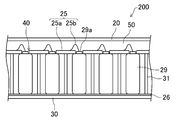
- FIG. 7 and 8 are diagrams showing a configuration of a battery module 200 according to another embodiment of the present invention, in which FIG. 7 is a cross-sectional view, and FIG. 8 is a plan view without a lid.
- the positive electrode side connection member 25 includes a main conductive path portion 25a having a plurality of through holes 40, and a plurality of connection terminals 25b for individually connecting the main conductive path portion 25a and the positive electrodes 29a of the plurality of batteries 29.
- the main conductive path portion 25a is disposed in contact with the shoulder portion of each battery 29, and the positive electrode 29a of each battery 29 is inserted into a through hole 40 provided in the main conductive path portion 25a.
- connection terminal 25b One end of each connection terminal 25b is connected to the positive electrode 29a of the battery 29, and the other end of the connection terminal 2b extends through the through hole 40 to the space 50 formed above the main conductive path portion 25a. Then, it is connected to the surface of the main conductive path portion 25a.
- connection terminal 25b when an internal short circuit occurs in the battery 29, the connection terminal 25b connected to the battery is melted by Joule heat. That is, in the present embodiment, the connection terminal 25b itself serves as the fuse portion 25c.
- the material of the connection terminal 25b is not particularly limited. For example, a metal thin wire such as Ni or Al or a metal ribbon can be used.
- the current flowing into the battery in which the internal short circuit occurs is 300 A by setting the cross-sectional area to 1 mm 2 in the relational expression described in the expression (1), it is due to Joule heat in the fuse portion 25c after 1 second. Since the temperature rise is about 1600 ° C. and the melting point of Ni is 1455 ° C., the fuse portion 25c is blown.
- the connection to the positive electrode 29a and the main conductive path portion 25a can be performed by wire bonding, laser welding, or the like.
- the high temperature gas discharged from the exhaust hole 17 of the battery 29 in which the internal short circuit has occurred is discharged to the space 50 on the main conductive path portion 25a through the through hole 40. It is possible to prevent the normal battery 29 from being exposed to the high temperature gas.
- the present invention is useful as a battery module or a battery connection member in a battery module that requires high reliability and safety such as an automobile, a bicycle, and an electric tool.
- Negative electrode 1 Positive electrode 1a Positive electrode current collector 1b Positive electrode layer 2 Negative electrode 3 Separator 4 Electrode group 5 Battery case 6 Sealing plate 7 Gasket 8 Positive lead 9 Negative lead 10a, 10b Insulating plate 11 Negative electrode current collector 15 Negative electrode layer 16 Positive cap 17 Exhaust hole 18 Current interrupting member 19 Vent mechanism 20 Lid 21 holes 25 Positive side connection member 25a Main conductive path 25b connection terminal 25c Fuse part 26 Negative side connection member 27 Positive terminal 28 Negative terminal 29 batteries 29a positive electrode 30 storage section 31 Bulkhead 40 Through hole 50 space 100, 200 battery module
Landscapes
- Chemical & Material Sciences (AREA)
- Chemical Kinetics & Catalysis (AREA)
- Electrochemistry (AREA)
- General Chemical & Material Sciences (AREA)
- Engineering & Computer Science (AREA)
- Materials Engineering (AREA)
- Manufacturing & Machinery (AREA)
- Connection Of Batteries Or Terminals (AREA)
- Battery Mounting, Suspending (AREA)
Abstract
Description
図1は、本発明の実施の形態1における電池モジュールを構成する電池の横断面図である。
=(I2・R・t)/(Cp・ρ・A・L)
=(I2・r・L/A・t)/(Cp・ρ・A・L)
=(I2・r・t)/(Cp・ρ・A2) ・・・式(1)
ここで、Cpは比熱容量、Mは質量、Rは抵抗、ρは密度、Lは長さ、rは電気抵抗率である。なお、式(1)から分かるように、温度上昇ΔTは、ヒューズ部25cの長さ(L)によらない。
1a 正極集電体
1b 正極層
2 負極
3 セパレータ
4 電極群
5 電池ケース
6 封口板
7 ガスケット
8 正極リード
9 負極リード
10a、10b 絶縁板
11 負極集電体
15 負極層
16 正極キャップ
17 排気孔
18 電流遮断部材
19 ベント機構
20 蓋体
21 穴
25 正極側接続部材
25a 主導電経路部
25b 接続端子
25c ヒューズ部
26 負極側接続部材
27 正極側端子
28 負極側端子
29 電池
29a 正極
30 収納部
31 隔壁
40 貫通孔
50 空間
100、200 電池モジュール
Claims (14)
- 複数の電池を並列に接続する電池接続部材であって、
主導電経路部と、
前記主導電経路部と前記複数の電池の一方の極とを個々に接続する複数の接続端子とを有し、
前記接続端子は、所定値以上の電流が流れたときに溶断されるヒューズ部を有し、
前記電池接続部材で前記複数の電池を並列に接続したとき、前記ヒューズ部は、前記電池と前記主導電経路部との空間に配置される、電池接続部材。 - 前記ヒューズ部は、前記接続端子と同一部材で一体的に形成されている、請求項1に記載の電池接続部材。
- 前記接続端子は、前記主導電経路部と同一部材で一体的に形成されている、請求項2に記載の電池接続部材。
- 前記接続端子の前記ヒューズ部における断面積は、前記接続端子の他の部分における断面積よりも小さい、請求項2に記載の電池接続部材。
- 前記接続端子は一様な幅を有し、前記接続端子の前記ヒューズ部における厚みは、前記接続端子の他の部分における厚みよりも薄い、請求項4に記載の電池接続部材。
- 前記接続端子の前記ヒューズ部における部材の抵抗は、前記接続端子の他の部分における部材の抵抗よりも大きい、請求項1に記載の電池接続部材。
- 前記ヒューズ部は、チップヒューズで構成されている、請求項6に記載の電池接続部材。
- 複数の電池が収納部に収納された電池モジュールであって、
前記複数の電池は、電池接続部材で並列に接続されており、
前記電池接続部材は、主導電経路部と、該主導電経路部と前記複数の電池の一方の極とを個々に接続する複数の接続端子とを有し、
前記接続端子は、所定値以上の電流が流れたときに溶断されるヒューズ部を有し、
前記ヒューズ部は、前記電池と前記主導電経路部との空間に配置されている、電池モジュール。 - 前記ヒューズ部は、前記接続端子と同一部材で一体的に形成されている、請求項8に記載の電池モジュール。
- 前記接続端子は、前記主導電経路部と同一部材で一体的に形成されている、請求項9に記載の電池モジュール。
- 前記接続端子の前記ヒューズ部における断面積は、前記接続端子の他の部分における断面積よりも小さい、請求項9に記載の電池モジュール。
- 前記接続端子は一様な幅を有し、前記接続端子の前記ヒューズ部における厚みは、前記接続端子の他の部分における厚みよりも薄い、請求項11に記載の電池モジュール。
- 前記接続端子の前記ヒューズ部における部材の抵抗は、前記接続端子の他の部分における部材の抵抗よりも大きい、請求項8に記載の電池モジュール。
- 前記ヒューズ部は、チップヒューズからなる、請求項13に記載の電池モジュール。
Priority Applications (4)
| Application Number | Priority Date | Filing Date | Title |
|---|---|---|---|
| US13/119,640 US9184426B2 (en) | 2009-07-17 | 2010-07-09 | Battery connection member and battery module using the same |
| CN201080004184.9A CN102272980B (zh) | 2009-07-17 | 2010-07-09 | 电池连接构件和使用该电池连接构件的电池模块 |
| JP2010550964A JP4815016B2 (ja) | 2009-07-17 | 2010-07-09 | 電池接続部材とそれを用いた電池モジュール |
| EP10799599A EP2339669B1 (en) | 2009-07-17 | 2010-07-09 | Battery connecting member and battery module using same |
Applications Claiming Priority (2)
| Application Number | Priority Date | Filing Date | Title |
|---|---|---|---|
| JP2009168518 | 2009-07-17 | ||
| JP2009-168518 | 2009-07-17 |
Publications (1)
| Publication Number | Publication Date |
|---|---|
| WO2011007535A1 true WO2011007535A1 (ja) | 2011-01-20 |
Family
ID=43449146
Family Applications (1)
| Application Number | Title | Priority Date | Filing Date |
|---|---|---|---|
| PCT/JP2010/004488 Ceased WO2011007535A1 (ja) | 2009-07-17 | 2010-07-09 | 電池接続部材とそれを用いた電池モジュール |
Country Status (6)
| Country | Link |
|---|---|
| US (1) | US9184426B2 (ja) |
| EP (1) | EP2339669B1 (ja) |
| JP (1) | JP4815016B2 (ja) |
| KR (1) | KR20120052189A (ja) |
| CN (1) | CN102272980B (ja) |
| WO (1) | WO2011007535A1 (ja) |
Cited By (13)
| Publication number | Priority date | Publication date | Assignee | Title |
|---|---|---|---|---|
| JP2011040368A (ja) * | 2009-08-14 | 2011-02-24 | Sb Limotive Co Ltd | 電池モジュール |
| WO2012053610A1 (ja) * | 2010-10-21 | 2012-04-26 | 株式会社キャプテックス | 電池接続具、組電池モジュール、組電池モジュールの製造方法および電池接続具の製造方法 |
| JP2012234698A (ja) * | 2011-04-28 | 2012-11-29 | Toyota Motor Corp | 蓄電装置 |
| WO2012164884A1 (ja) | 2011-05-31 | 2012-12-06 | パナソニック株式会社 | ヒューズ板、およびそれを具備する電池ブロック |
| JP2014110139A (ja) * | 2012-11-30 | 2014-06-12 | Toyota Motor Corp | 組電池及び車両 |
| WO2014119286A1 (ja) * | 2013-01-29 | 2014-08-07 | 三洋電機株式会社 | 電極部材、および、電池ブロック |
| WO2014125806A1 (ja) * | 2013-02-14 | 2014-08-21 | 三洋電機株式会社 | 電池ブロック |
| JP2015141800A (ja) * | 2014-01-28 | 2015-08-03 | ダイキョーニシカワ株式会社 | 電池モジュール |
| WO2016072054A1 (ja) * | 2014-11-04 | 2016-05-12 | パナソニックIpマネジメント株式会社 | 電極部材および集電板、電池ブロック |
| JP2018521446A (ja) * | 2015-05-11 | 2018-08-02 | ゴゴロ インク | 可搬型多セル電気エネルギー貯蔵装置用電気コネクタ |
| WO2020066055A1 (ja) * | 2018-09-26 | 2020-04-02 | パナソニックIpマネジメント株式会社 | 電池モジュール |
| WO2025082040A1 (zh) * | 2023-10-20 | 2025-04-24 | 宁德时代新能源科技股份有限公司 | 端盖组件、电池单体、电池和用电装置 |
| WO2025094672A1 (ja) * | 2023-10-30 | 2025-05-08 | パナソニックIpマネジメント株式会社 | 電源装置及びヒューズリンク機能を備えるリード板並びにこれらの製造方法 |
Families Citing this family (32)
| Publication number | Priority date | Publication date | Assignee | Title |
|---|---|---|---|---|
| EP2555280B1 (en) * | 2011-08-05 | 2016-11-02 | Optimum Battery Co., Ltd. | Improved electrode board having security device and power battery system using same |
| CN103022578B (zh) * | 2011-09-22 | 2016-05-18 | 深圳市沃特玛电池有限公司 | 一种动力电池组的安全结构 |
| JP5930047B2 (ja) * | 2011-09-16 | 2016-06-08 | エルジー・ケム・リミテッド | 二次電池用部品及びその製造方法、並びに該部品を使用して製造された二次電池及び組立二次電池装置 |
| US9203117B2 (en) * | 2012-05-04 | 2015-12-01 | Samsung Sdi Co., Ltd. | Rechargeable secondary battery |
| KR101367197B1 (ko) * | 2012-07-30 | 2014-02-25 | 에너지 컨트롤 리미티드 | 이차 전지 팩 |
| US20140212695A1 (en) * | 2013-01-30 | 2014-07-31 | Tesla Motors, Inc. | Flexible printed circuit as high voltage interconnect in battery modules |
| JP6006134B2 (ja) * | 2013-02-08 | 2016-10-12 | トヨタ自動車株式会社 | 接続部材 |
| US9985259B2 (en) * | 2013-03-29 | 2018-05-29 | Sanyo Electric Co., Ltd. | Battery pack |
| CN104241730B (zh) * | 2013-06-13 | 2018-03-20 | 南京德朔实业有限公司 | 具有散热系统的电池包 |
| KR101696010B1 (ko) | 2013-06-19 | 2017-01-12 | 삼성에스디아이 주식회사 | 이차 전지 |
| KR102073193B1 (ko) * | 2013-09-23 | 2020-02-04 | 삼성에스디아이 주식회사 | 배터리 팩 |
| US10103365B2 (en) * | 2013-12-31 | 2018-10-16 | Chervon (Hk) Limited | Battery pack |
| KR102172843B1 (ko) * | 2014-03-20 | 2020-11-02 | 삼성에스디아이 주식회사 | 이차 전지 |
| KR102248595B1 (ko) | 2014-04-15 | 2021-05-06 | 삼성에스디아이 주식회사 | 이차 전지 |
| TWI495179B (zh) * | 2014-06-17 | 2015-08-01 | Energy Control Ltd | 以二導電條將複數二次電池並聯而構成集合電池的結構 |
| US10211443B2 (en) * | 2014-09-10 | 2019-02-19 | Cellink Corporation | Battery interconnects |
| US9741997B2 (en) | 2014-11-05 | 2017-08-22 | Samsung Sdi Co., Ltd. | Rechargeable battery |
| DE102016116581A1 (de) * | 2016-06-03 | 2018-03-01 | E-Seven Systems Technology Management Ltd | Verbindungsplatte für eine Batterie und Batterie |
| EP3282501B1 (de) * | 2016-08-08 | 2020-05-13 | Voltlabor GmbH | Batterie, batteriemodul für die batterie und stromschiene hierfür |
| EP3316352B1 (en) * | 2016-10-27 | 2021-03-24 | Robert Bosch GmbH | Safety test method for determination of critical cell states by internal short circuit provocation |
| US20180138478A1 (en) * | 2016-11-14 | 2018-05-17 | Anhui Xinen Technology Co., Ltd. | Alleviating explosion propagation in a battery module |
| KR102332338B1 (ko) * | 2017-06-01 | 2021-11-29 | 삼성에스디아이 주식회사 | 배터리 팩 |
| CN110998898B (zh) * | 2017-07-13 | 2023-03-10 | 电控装置有限责任公司 | 用于叉车的模块化锂离子电池系统 |
| KR102350459B1 (ko) | 2017-12-07 | 2022-01-11 | 주식회사 엘지에너지솔루션 | 원통형 이차전지 모듈 |
| JP7105081B2 (ja) | 2018-03-29 | 2022-07-22 | 三洋電機株式会社 | 組電池、及び、これに用いられる二次電池 |
| KR102487835B1 (ko) * | 2019-01-16 | 2023-01-12 | 주식회사 엘지에너지솔루션 | 충전 시간을 단축시킨 이차전지의 충전 방법 |
| US11527792B2 (en) | 2019-03-14 | 2022-12-13 | Generac Power Systems, Inc. | Battery module thermal management |
| CN111186302A (zh) * | 2020-01-14 | 2020-05-22 | 中车资阳机车有限公司 | 一种纯电动轨道机车动力电池安全保障方法 |
| KR102805964B1 (ko) * | 2021-01-22 | 2025-05-09 | 주식회사 엘지에너지솔루션 | 전지 모듈 및 이를 포함하는 전지 팩 |
| KR20230160239A (ko) | 2021-03-24 | 2023-11-23 | 셀링크 코포레이션 | 다층 가요성 배터리 인터커넥트 및 이의 제조 방법 |
| CN222720627U (zh) * | 2021-07-20 | 2025-04-04 | 米沃奇电动工具公司 | 电池组 |
| CN117813725A (zh) * | 2021-09-10 | 2024-04-02 | 小鹰公司 | 具有圆柱形电池电芯和带式接合的电池系统 |
Citations (7)
| Publication number | Priority date | Publication date | Assignee | Title |
|---|---|---|---|---|
| JPS6450281A (en) | 1987-08-21 | 1989-02-27 | Teac Corp | Magnetic reproducing device |
| JPH06231748A (ja) * | 1993-02-05 | 1994-08-19 | Ngk Insulators Ltd | 単電池の並列接続ブス及び接続構造 |
| JPH10270006A (ja) * | 1997-03-24 | 1998-10-09 | Toyota Motor Corp | 電池電源装置とこれに用いるエンドプレート |
| JP2000223095A (ja) * | 1999-01-28 | 2000-08-11 | Sanyo Electric Co Ltd | 電源装置 |
| JP2000223165A (ja) * | 1999-01-29 | 2000-08-11 | Sanyo Electric Co Ltd | 電源装置 |
| JP2002025510A (ja) | 2000-07-05 | 2002-01-25 | Gs-Melcotec Co Ltd | 電池パック |
| JP2009231138A (ja) * | 2008-03-24 | 2009-10-08 | Toshiba Corp | 電池パック |
Family Cites Families (15)
| Publication number | Priority date | Publication date | Assignee | Title |
|---|---|---|---|---|
| DE69218587T2 (de) | 1991-12-06 | 1997-08-14 | Yuasa Battery Co Ltd | Dünne batterie und monolitische dünne batterie |
| US5419983A (en) * | 1993-07-20 | 1995-05-30 | Matsushita Electric Industrial Co., Ltd. | Lead acid battery |
| JP3658877B2 (ja) * | 1996-08-01 | 2005-06-08 | 松下電器産業株式会社 | バッテリーパック |
| EP1030390B1 (en) * | 1997-03-24 | 2004-02-04 | Matsushita Electric Industrial Co., Ltd. | Battery power source unit |
| DE10002142B4 (de) * | 1999-01-28 | 2004-04-29 | Sanyo Electric Co., Ltd., Moriguchi | Stromversorgung enthaltend wiederaufladbare Batterien |
| WO2001069699A1 (en) * | 2000-03-14 | 2001-09-20 | Matsushita Electric Industrial Co., Ltd. | Secondary cell and method for bonding lead thereof, and battery power supply |
| EP1313193A1 (en) * | 2001-11-19 | 2003-05-21 | Dialog Semiconductor GmbH | Battery protection system with sequential blowing fuse |
| KR100551396B1 (ko) * | 2003-10-15 | 2006-02-09 | 삼성에스디아이 주식회사 | 일체형 캡조립체를 갖는 이차전지 및 일체형 캡조립체형성 방법 |
| KR100876456B1 (ko) * | 2004-12-24 | 2008-12-29 | 주식회사 엘지화학 | 분리형 커넥팅 부재 및 그것을 이용한 이차전지 모듈의제조방법 |
| EP1829138A4 (en) * | 2004-12-24 | 2012-06-13 | Lg Chemical Ltd | SEPARABLE CONNECTOR FOR A SECONDARY BATTERY MODULE AND METHOD FOR IMPROVING THE PERFORMANCE OF A BATTERY MODULE THROUGH A LEVELING VOLTAGE |
| CN101017887B (zh) * | 2005-11-28 | 2010-06-16 | Nec东金株式会社 | 电池层叠体及电池组件 |
| JP5010250B2 (ja) * | 2005-11-28 | 2012-08-29 | Necエナジーデバイス株式会社 | 電池積層体および電池パック |
| US7671565B2 (en) * | 2006-02-13 | 2010-03-02 | Tesla Motors, Inc. | Battery pack and method for protecting batteries |
| CN2935488Y (zh) | 2006-08-15 | 2007-08-15 | 深圳市格瑞普电池有限公司 | 具有短路保护功能的电池组 |
| US7923144B2 (en) * | 2007-03-31 | 2011-04-12 | Tesla Motors, Inc. | Tunable frangible battery pack system |
-
2010
- 2010-07-09 EP EP10799599A patent/EP2339669B1/en active Active
- 2010-07-09 JP JP2010550964A patent/JP4815016B2/ja active Active
- 2010-07-09 KR KR1020117005812A patent/KR20120052189A/ko not_active Withdrawn
- 2010-07-09 WO PCT/JP2010/004488 patent/WO2011007535A1/ja not_active Ceased
- 2010-07-09 CN CN201080004184.9A patent/CN102272980B/zh active Active
- 2010-07-09 US US13/119,640 patent/US9184426B2/en active Active
Patent Citations (7)
| Publication number | Priority date | Publication date | Assignee | Title |
|---|---|---|---|---|
| JPS6450281A (en) | 1987-08-21 | 1989-02-27 | Teac Corp | Magnetic reproducing device |
| JPH06231748A (ja) * | 1993-02-05 | 1994-08-19 | Ngk Insulators Ltd | 単電池の並列接続ブス及び接続構造 |
| JPH10270006A (ja) * | 1997-03-24 | 1998-10-09 | Toyota Motor Corp | 電池電源装置とこれに用いるエンドプレート |
| JP2000223095A (ja) * | 1999-01-28 | 2000-08-11 | Sanyo Electric Co Ltd | 電源装置 |
| JP2000223165A (ja) * | 1999-01-29 | 2000-08-11 | Sanyo Electric Co Ltd | 電源装置 |
| JP2002025510A (ja) | 2000-07-05 | 2002-01-25 | Gs-Melcotec Co Ltd | 電池パック |
| JP2009231138A (ja) * | 2008-03-24 | 2009-10-08 | Toshiba Corp | 電池パック |
Non-Patent Citations (1)
| Title |
|---|
| See also references of EP2339669A4 |
Cited By (29)
| Publication number | Priority date | Publication date | Assignee | Title |
|---|---|---|---|---|
| US8338021B2 (en) | 2009-08-14 | 2012-12-25 | Sb Limotive Co., Ltd. | Battery module |
| JP2011040368A (ja) * | 2009-08-14 | 2011-02-24 | Sb Limotive Co Ltd | 電池モジュール |
| WO2012053610A1 (ja) * | 2010-10-21 | 2012-04-26 | 株式会社キャプテックス | 電池接続具、組電池モジュール、組電池モジュールの製造方法および電池接続具の製造方法 |
| JP2012234698A (ja) * | 2011-04-28 | 2012-11-29 | Toyota Motor Corp | 蓄電装置 |
| US10566165B2 (en) | 2011-05-31 | 2020-02-18 | Panasonic Intellectual Property Management Co., Ltd. | Fuse board and battery block equipped with same |
| KR101432459B1 (ko) * | 2011-05-31 | 2014-08-20 | 파나소닉 주식회사 | 퓨즈판, 및 그것을 구비하는 전지 블록 |
| US20130202941A1 (en) * | 2011-05-31 | 2013-08-08 | Panasonic Corporation | Fuse board and battery block equipped with same |
| JP2013219052A (ja) * | 2011-05-31 | 2013-10-24 | Panasonic Corp | ヒューズ板、およびそれを具備する電池ブロック |
| JP2013127973A (ja) * | 2011-05-31 | 2013-06-27 | Panasonic Corp | ヒューズ板、およびそれを具備する電池ブロック |
| WO2012164884A1 (ja) | 2011-05-31 | 2012-12-06 | パナソニック株式会社 | ヒューズ板、およびそれを具備する電池ブロック |
| JPWO2012164884A1 (ja) * | 2011-05-31 | 2015-02-23 | パナソニック株式会社 | ヒューズ板、およびそれを具備する電池ブロック |
| JP2014110139A (ja) * | 2012-11-30 | 2014-06-12 | Toyota Motor Corp | 組電池及び車両 |
| JP2014146516A (ja) * | 2013-01-29 | 2014-08-14 | Sanyo Electric Co Ltd | 電極部材、および、電池ブロック |
| WO2014119286A1 (ja) * | 2013-01-29 | 2014-08-07 | 三洋電機株式会社 | 電極部材、および、電池ブロック |
| US9812694B2 (en) | 2013-01-29 | 2017-11-07 | Sanyo Electric Co., Ltd. | Electrode member and battery block |
| WO2014125806A1 (ja) * | 2013-02-14 | 2014-08-21 | 三洋電機株式会社 | 電池ブロック |
| JPWO2014125806A1 (ja) * | 2013-02-14 | 2017-02-02 | 三洋電機株式会社 | 電池ブロック |
| US10396326B2 (en) | 2013-02-14 | 2019-08-27 | Sanyo Electric Co., Ltd. | Battery block |
| JP2015141800A (ja) * | 2014-01-28 | 2015-08-03 | ダイキョーニシカワ株式会社 | 電池モジュール |
| JPWO2016072054A1 (ja) * | 2014-11-04 | 2017-08-10 | パナソニックIpマネジメント株式会社 | 電極部材および集電板、電池ブロック |
| WO2016072054A1 (ja) * | 2014-11-04 | 2016-05-12 | パナソニックIpマネジメント株式会社 | 電極部材および集電板、電池ブロック |
| JP2018521446A (ja) * | 2015-05-11 | 2018-08-02 | ゴゴロ インク | 可搬型多セル電気エネルギー貯蔵装置用電気コネクタ |
| US11165123B2 (en) | 2015-05-11 | 2021-11-02 | Gogoro Inc. | Electrical connector positioned in a battery pack |
| WO2020066055A1 (ja) * | 2018-09-26 | 2020-04-02 | パナソニックIpマネジメント株式会社 | 電池モジュール |
| JPWO2020066055A1 (ja) * | 2018-09-26 | 2021-08-30 | パナソニックIpマネジメント株式会社 | 電池モジュール |
| JP7320792B2 (ja) | 2018-09-26 | 2023-08-04 | パナソニックIpマネジメント株式会社 | 電池モジュール |
| US11824226B2 (en) | 2018-09-26 | 2023-11-21 | Panasonic Intellectual Property Management Co., Ltd. | Battery module |
| WO2025082040A1 (zh) * | 2023-10-20 | 2025-04-24 | 宁德时代新能源科技股份有限公司 | 端盖组件、电池单体、电池和用电装置 |
| WO2025094672A1 (ja) * | 2023-10-30 | 2025-05-08 | パナソニックIpマネジメント株式会社 | 電源装置及びヒューズリンク機能を備えるリード板並びにこれらの製造方法 |
Also Published As
| Publication number | Publication date |
|---|---|
| CN102272980B (zh) | 2014-08-27 |
| KR20120052189A (ko) | 2012-05-23 |
| US9184426B2 (en) | 2015-11-10 |
| EP2339669A1 (en) | 2011-06-29 |
| JPWO2011007535A1 (ja) | 2012-12-20 |
| EP2339669B1 (en) | 2013-03-13 |
| JP4815016B2 (ja) | 2011-11-16 |
| EP2339669A4 (en) | 2012-02-29 |
| CN102272980A (zh) | 2011-12-07 |
| US20110177365A1 (en) | 2011-07-21 |
Similar Documents
| Publication | Publication Date | Title |
|---|---|---|
| JP4815016B2 (ja) | 電池接続部材とそれを用いた電池モジュール | |
| US8399112B2 (en) | Battery module and battery pack using the same | |
| US8062785B2 (en) | Battery module and battery pack using the same | |
| US8475952B2 (en) | Battery module and battery pack using the same | |
| JP4973824B2 (ja) | 電池モジュール | |
| WO2010067602A1 (ja) | 電池モジュールとそれを用いた電池モジュール集合体 | |
| WO2010098067A1 (ja) | 電池モジュールとそれを用いた電池モジュール集合体 | |
| WO2009110167A1 (ja) | 電池モジュールおよびそれらを用いた電池パック | |
| WO2012014398A1 (ja) | 電池モジュール及びそれを用いた電池パック | |
| JP2000090976A (ja) | リチウム二次電池モジュール |
Legal Events
| Date | Code | Title | Description |
|---|---|---|---|
| WWE | Wipo information: entry into national phase |
Ref document number: 201080004184.9 Country of ref document: CN |
|
| ENP | Entry into the national phase |
Ref document number: 2010550964 Country of ref document: JP Kind code of ref document: A |
|
| WWE | Wipo information: entry into national phase |
Ref document number: 2010799599 Country of ref document: EP |
|
| ENP | Entry into the national phase |
Ref document number: 20117005812 Country of ref document: KR Kind code of ref document: A |
|
| 121 | Ep: the epo has been informed by wipo that ep was designated in this application |
Ref document number: 10799599 Country of ref document: EP Kind code of ref document: A1 |
|
| WWE | Wipo information: entry into national phase |
Ref document number: 13119640 Country of ref document: US |
|
| NENP | Non-entry into the national phase |
Ref country code: DE |