WO2011007812A1 - ハウリングキャンセラ - Google Patents
ハウリングキャンセラ Download PDFInfo
- Publication number
- WO2011007812A1 WO2011007812A1 PCT/JP2010/061922 JP2010061922W WO2011007812A1 WO 2011007812 A1 WO2011007812 A1 WO 2011007812A1 JP 2010061922 W JP2010061922 W JP 2010061922W WO 2011007812 A1 WO2011007812 A1 WO 2011007812A1
- Authority
- WO
- WIPO (PCT)
- Prior art keywords
- howling
- frequency component
- microphone
- frequency
- microphones
- Prior art date
- Legal status (The legal status is an assumption and is not a legal conclusion. Google has not performed a legal analysis and makes no representation as to the accuracy of the status listed.)
- Ceased
Links
Images


Classifications
-
- H—ELECTRICITY
- H04—ELECTRIC COMMUNICATION TECHNIQUE
- H04M—TELEPHONIC COMMUNICATION
- H04M9/00—Arrangements for interconnection not involving centralised switching
- H04M9/08—Two-way loud-speaking telephone systems with means for conditioning the signal, e.g. for suppressing echoes for one or both directions of traffic
- H04M9/082—Two-way loud-speaking telephone systems with means for conditioning the signal, e.g. for suppressing echoes for one or both directions of traffic using echo cancellers
-
- H—ELECTRICITY
- H04—ELECTRIC COMMUNICATION TECHNIQUE
- H04R—LOUDSPEAKERS, MICROPHONES, GRAMOPHONE PICK-UPS OR LIKE ACOUSTIC ELECTROMECHANICAL TRANSDUCERS; ELECTRIC HEARING AIDS; PUBLIC ADDRESS SYSTEMS
- H04R3/00—Circuits for transducers
- H04R3/02—Circuits for transducers for preventing acoustic reaction, i.e. acoustic oscillatory feedback
Definitions
- This invention relates to a howling canceller that suppresses howling that occurs in an acoustic feedback system.
- the howling canceller of Patent Document 1 includes a plurality of notch filters, and is connected between a microphone and an amplifier at the subsequent stage.
- a howling canceller detects a frequency component in which howling occurs, the howling canceller suppresses howling by assigning a notch filter to the detected frequency.
- Patent Document 1 shows a case where howling is suppressed in a system in which there is one microphone and one speaker, howling is suppressed by simply assigning a notch filter to a frequency at which howling is detected. Can do.
- an acoustic feedback system is configured for each microphone. It is not possible to simply determine whether howling has occurred in the (microphone collected signal).
- the howling canceller of Patent Document 1 is connected to the subsequent stage of each microphone.
- all howling cancellers connected to the subsequent stage of each microphone assign a notch filter to the same frequency as the frequency component in which howling occurs.
- howling occurs only for the collected sound signal of the microphone in which howling occurs in an environment where the synthesized sound signal obtained by combining the sound collected signals of a plurality of microphones is emitted from the speaker. It is an object of the present invention to provide a howling canceller capable of attenuating a frequency component.
- a howling canceller is applied to an acoustic system having a speaker and a plurality of microphones, and a plurality of acoustic feedback systems are formed by the speakers and the microphones. , Detecting a frequency component in which howling may occur for each collected sound signal of each microphone, and comparing each detected frequency component of the collected sound signal of each microphone for each frequency.
- a howling canceller provided with a howling suppression means for detecting a frequency component having a maximum power and performing a suppression process for suppressing the frequency component having the maximum power in a collected sound signal including the frequency component having the maximum power.
- the howling suppression means is detected by a howling possibility detecting means for detecting a frequency component in which howling may occur for each of collected sound signals of the plurality of microphones, and the howling possibility detecting means. And a howling determination means for comparing frequency components for each collected sound signal for each frequency and determining a frequency component having the maximum power for each frequency, wherein the howling suppression means is determined by the howling determination means Based on the result, a notch filter that suppresses the frequency component is inserted into the collected sound signal including the determined frequency component.
- the howling possibility detecting unit is configured to use the predetermined frequency component as a frequency component that may cause the howling when the power of the frequency component for each of the collected sound signals of the plurality of microphones is equal to or higher than a predetermined value.
- a frequency component having a power greater than or equal to the value is detected.
- the howling suppression means is provided between each microphone and a synthesizing means for synthesizing collected sound signals from the plurality of microphones.
- the howling suppression means repeatedly performs the suppression process.
- the howling canceller of the present invention can suppress only the frequency component of the collected sound signal in which howling occurs in an acoustic system having a plurality of acoustic feedback systems. Thereby, the howling canceller can prevent the frequency component of the collected sound signal that should not be suppressed from being suppressed.
- FIG. 1 is a block diagram illustrating functions and configurations of an acoustic system according to Example 1.
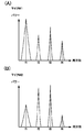
- FIG. (A) and (B) are examples showing frequency components in which howling may occur. It is a flowchart which shows the flow of howling suppression processing.
- 6 is a block diagram illustrating functions and configurations of an acoustic system according to Embodiment 2.
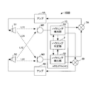
- FIG. 1 is a block diagram showing the function and configuration of an acoustic system. As shown in FIG. 1, the acoustic system 100A includes a microphone M1, a microphone M2, a howling canceller 10, an adder 3, an amplifier 4, and a speaker S.
- the acoustic system 100A adds the audio signals collected by the microphone M1 and the microphone M2 (hereinafter referred to as the “sound collection signal”) by the adder 3, amplifies it by the amplifier 4, and outputs it to the speaker S.
- the microphone M1 and the microphone M2 again collect the sound emitted from the speaker S depending on the positional relationship between the speaker S and the microphones M1 and M2 and the environment in which these speakers are disposed.
- An acoustic feedback system is formed.
- the sound collected signals of the microphone M1 and the microphone M2 include the sound signal emitted from the speaker S (including the sound collected signals of the microphone M1 and the microphone M2).
- the collected sound signal of M2 is repeatedly amplified by the amplifier 4, and the specific frequency component may be strengthened depending on the situation.
- howling occurs when the loop gain for the specific frequency exceeds 1. Therefore, in this acoustic system 100A, the howling canceller 10 performs howling suppression processing to suppress howling that occurs in this way.
- the acoustic feedback system L1 includes a microphone M1, a howling canceller 10, an adder 3, an amplifier 4, and a speaker S.
- the acoustic feedback system L2 includes a microphone M2, a howling canceller 10, an adder 3, an amplifier 4, and a speaker S.
- the microphone M1 and the microphone M2 each output a sound collection signal to the howling canceller 10.
- the howling canceller 10 includes a howling detection unit 1A, a howling detection unit 1B, and a howling determination unit 2, and suppresses howling occurring in the acoustic feedback system L1 and the acoustic feedback system L2.
- a sound collection signal from the microphone M1 is input to the howling detection unit 1A of the howling canceller 10, and a sound collection signal from the microphone M2 is input to the howling detection unit 1B.
- howling detection unit 1 ⁇ / b> A and howling detection unit 1 ⁇ / b> B have the same function and configuration, and therefore will be described as howling detection unit 1.
- the howling detection unit 1 includes an FFT processing unit 11, a howling possibility detection unit 12, and a notch filter 13.
- the collected sound signal is input to the FFT processing unit 11 and the notch filter 13.
- the FFT processing unit 11 is a fast Fourier transform processing circuit, converts a sound collection signal that is a function in the time domain into a sound collection signal that is a function in the frequency domain, and outputs the sound collection signal to the howling possibility detection unit 12.
- the howling possibility detection unit 12 detects, for example, that there is a possibility that howling has occurred in the frequency when the power of the frequency component is equal to or higher than a predetermined value.
- the howling possibility detection unit 12 outputs information on frequency components that may cause howling as illustrated in FIGS. 2A and 2B to the howling determination unit 2.
- FIGS. 2A and 2B are examples showing frequency components in which howling may occur, with the horizontal axis representing frequency and the vertical axis representing power value.
- FIG. 2A shows a sound collection signal of the microphone M1
- FIG. 2B shows a sound collection signal of the microphone M2.
- the howling determination unit 2 compares the frequency components input from the howling possibility detection units 12 of the howling detection unit 1A and the howling detection unit 1B with each other, and compares the frequency components with a larger power (the microphone in FIG. 2A). F1 and f4 frequency components of M1, and f2 and f3 frequency components of microphone M2 in FIG. 2B) are determined for each frequency. It is determined that the frequency component of the higher power corresponds to the frequency component that causes howling, and the howling determination unit 2 suppresses the frequency component of the higher power to each notch filter 13 of the howling detection unit 1A and the howling detection unit 1B. Set the coefficients individually.
- the notch filter 13 is an adaptive IIR filter, for example, and suppresses the frequency component by abruptly decreasing the gain of the narrowband frequency component.
- the notch filter 13 outputs to the adder 3 an audio signal in which a greater power frequency component (frequency component in which howling is generated) is suppressed from the collected sound signal.
- the notch filter 13 of the howling detection unit 1A attenuates the frequency components of f1 and f4 and does not attenuate the frequency components of f2 and f3.
- the signal is output to the adder 3.
- the notch filter 13 of the howling detection unit 1B attenuates the frequency components f2 and f3 and outputs the audio signal to the adder 3 without attenuating the frequency components f1 and f4.
- the adder 3 adds the input audio signals and outputs them to the amplifier 4. That is, the adder 3 adds the audio signal in which the frequency component that is howling from the sound collection signal of the microphone M1 is suppressed and the audio signal in which the frequency component that is howling from the sound collection signal of the microphone M2 is suppressed.
- the amplifier 4 amplifies the audio signal input from the adder 3 and outputs it to the speaker S.
- Speaker S emits sound based on the input audio signal.
- the howling canceller 10 can specify the frequency at which howling is generated for each collected sound signal of the microphone, and therefore suppresses only the frequency component at which howling is generated for each collected sound signal of the microphone. Can do. That is, the howling canceller 10 does not erroneously suppress the frequency component of the collected sound signal of the microphone in which no howling has occurred with respect to the frequency in which howling is generated in the collected sound signal of another microphone. As a result, the howling canceller 10 does not suppress the frequency component of the collected sound signal more than necessary, and rarely degrades the output audio signal.
- FIG. 3 is a flowchart showing the flow of howling suppression processing.
- the microphone M ⁇ b> 1 picks up surrounding sounds and generates a picked-up signal, and sends the picked-up signal to the FFT processing unit 11 of the howling detection unit 1 ⁇ / b> A of the howling canceller 10 and the notch filter 13. Output. Further, the microphone M2 collects ambient sounds, generates a collected sound signal, and outputs the collected sound signal to the FFT processing unit 11 and the notch filter 13 of the howling detection unit 1B (S101).
- Each of the FFT processing units 11 of the howling detection unit 1A and the howling detection unit 1B converts the input sound pickup signal into a frequency spectrum and outputs the frequency spectrum to the howling possibility detection unit 12 (S102).
- Each howling possibility detection unit 12 of the howling detection unit 1A and howling detection unit 1B detects that there is a possibility of howling to a frequency component having a power of a predetermined value or more from the frequency spectrum, and determines howling.
- the detected frequency component is output to the unit 2 (S103).
- the howling determination unit 2 compares the frequency components input from the howling possibility detection units 12 of the howling detection unit 1A and the howling detection unit 1B, respectively, and determines a frequency component of larger power for each frequency (S104). .
- the howling determination unit 2 sets coefficients individually in the notch filters 13 of the howling detection unit 1A and the howling detection unit 1B so as to suppress the frequency component of the higher power (S105).
- Each notch filter 13 of the howling detection unit 1A and the howling detection unit 1B outputs to the adder 3 an audio signal in which a frequency component having a larger power is suppressed from the collected sound signals input from the microphone M1 and the microphone M2, respectively.
- the audio signal added by the adder 3 is amplified by the amplifier 4 and output to the speaker S (S106). And it returns to the process of S101 and a process is repeated sequentially.
- the howling canceller 10 can suppress frequency components that are not suppressed by one howling suppression processing by repeatedly performing howling suppression processing. Therefore, the howling canceller 10 can accurately and reliably suppress howling occurring in the acoustic system 100A.
- the above-described processing results in the acoustic Even if the howling suppression of the component of the frequency f1 of the feedback system L1 is performed, the component of the frequency f1 of the acoustic feedback system L2 remains. However, by repeatedly performing the howling suppression processing, the howling can also be detected for the component of the frequency f1 of the acoustic feedback system L2 that could not be suppressed, and the howling can be suppressed.
- the number of microphones is not limited to two but may be plural.
- the howling canceller 10 may include as many howling detection units 1 as the number of acoustic feedback systems.
- the howling canceller 10 is applied to an acoustic system 100B having two speakers and two microphones.
- FIG. 4 is a block diagram illustrating functions and configurations of the acoustic system according to the second embodiment.
- the acoustic system 100B includes a microphone M1, a microphone M2, a howling canceller 10, an adder 3A, an adder 3B, an amplifier 4A, an amplifier 4B, a speaker S1, and a speaker S2.
- the acoustic system 100B in FIG. 4 adds the collected sound signals of the microphone M1 and the microphone M2 by the adder 3A and the adder 3B, and amplifies the audio signal output from the adder 3A by the amplifier 4A.
- the audio signal output from the device 3B is amplified by the amplifier 4B.
- the acoustic system 100B outputs the audio signal amplified by the amplifier 4A to the speaker S1, and outputs the audio signal amplified by the amplifier 4B to the speaker S2.
- an acoustic feedback system is formed in which the microphone M1 and the microphone M2 again collect the sound emitted from the speakers S1 and S2.
- the sound collected signals of the microphone M1 and the microphone M2 include the sound signals (including the sound collected signals of the microphone M1 and the microphone M2) emitted by the speaker S1 and the speaker S2.
- the collected sound signals of the microphone M1 and the microphone M2 are repeatedly amplified by the amplifier 4A and the amplifier 4B, and the specific frequency component may be strengthened depending on the situation. As a result, when the loop gain for the frequency exceeds 1, howling occurs. Therefore, in the acoustic system 100B, the howling canceller 10 performs howling suppression processing to suppress howling that occurs in this way.
- the acoustic feedback system L11 includes a microphone M1, a howling canceller 10, an adder 3A, an amplifier 4A, and a speaker S1.
- the acoustic feedback system L12 includes a microphone M1, a howling canceller 10, an adder 3B, an amplifier 4B, and a speaker S2.
- the acoustic feedback system L21 includes a microphone M2, a howling canceller 10, an adder 3A, an amplifier 4A, and a speaker S1.
- the acoustic feedback system L22 includes a microphone M2, a howling canceller 10, an adder 3B, an amplifier 4B, and a speaker S2.
- the sound collected signals of the microphone M1 and the microphone M2 are output to the howling detection unit 1A and the howling detection unit 1B of the howling canceller 10, respectively.
- the collected sound signal of the microphone M1 includes an audio signal from the speaker S1 (audio signal via the acoustic feedback system L11) and an audio signal from the speaker S2 (audio signal via the acoustic feedback system L12).
- the sound collection signal of the microphone M2 includes an audio signal from the speaker S1 (audio signal via the acoustic feedback system L21) and an audio signal from the speaker S2 (audio signal via the acoustic feedback system L22).
- the howling detection unit 1A detects a frequency component in which howling may occur from the collected sound signal of the microphone M1, and the howling detection unit 1B detects howling from the collected sound signal of the microphone M2. Detect frequency components that may have occurred. Then, the howling determination unit 2 compares the frequency components detected by the howling detection unit 1A and the howling detection unit 1B, respectively, and determines a frequency component having a larger power for each frequency. The howling determination unit 2 sets coefficients in the notch filter 13 of the howling detection unit 1A and the notch filter 13 of the howling detection unit 1B so as to suppress a frequency component of a larger power.
- the howling canceller 10 can specify the frequency component in which howling is generated for each collected sound signal of the microphone. For this reason, the howling canceller 10 can suppress only the sound collection signal of the microphone including the frequency component in which howling has occurred in the sound collection signal of another microphone. That is, the howling canceller 10 does not suppress the frequency component having the same frequency as the frequency component in which howling is generated from the collected sound signal of the microphone that is determined not to include the frequency component in which howling is generated. As a result, the howling canceller 10 does not suppress the frequency component of the collected sound signal more than necessary, and rarely degrades the output audio signal.
- howling can be suppressed more accurately and reliably by repeatedly executing the howling suppression processing.
- the howling canceller 10 may include the howling detection units 1 as many as the number of microphones.
- the howling canceller of the present invention is applied to an acoustic system having one or a plurality of speakers and a plurality of microphones.
- the acoustic system includes a plurality of acoustic feedback systems that emit sound from the speaker based on a sound collection signal from the microphone and collect sound emitted from the speaker by the microphone.
- the howling canceller has howling suppression means for performing suppression processing for suppressing howling.
- the howling suppression unit detects a frequency at which howling may occur for each sound collection signal of the microphone. For example, the howling suppression unit performs an FFT process for each collected sound signal of a microphone, and detects a frequency component having a power value equal to or higher than a predetermined value as a frequency component that may cause howling.
- Howling suppression means compares the frequency components detected for each microphone collected signal, detects a collected signal with higher power (maximum power) for each frequency, and howling occurs for each collected signal Suppresses frequency components
- the howling canceller can suppress only the frequency component of the collected sound signal of the microphone in which howling occurs in the acoustic system having a plurality of acoustic feedback systems, and the frequency of the collected sound signal of the microphone in which no howling has occurred. Does not suppress ingredients. For this reason, the howling canceller can suppress the generated howling without substantially degrading the audio signal.
- the howling suppression means of the howling canceller of the present invention has a howling detection means and a howling determination means.
- the howling detection means detects a frequency component in which howling may occur for each collected sound signal of the microphone.
- the howling determination means detects a frequency component having a larger power for each frequency from frequency components that may cause howling.
- the howling determination means determines a sound collection signal of a microphone that performs howling for each frequency, assuming that a frequency component having a larger power for each detected frequency is a frequency component that causes howling.
- the howling detection means inserts a notch filter for each acoustic feedback system based on the determination result of the howling determination means, that is, to suppress the frequency component determined to be howling.
- howling canceller of the present invention connects howling suppression means immediately after the microphone.
- the howling canceller performs the howling suppression process before the collected sound signals of a plurality of microphones are synthesized, the howling canceller can suppress the frequency component that causes howling for each sound signal collected by the microphones.
- the howling canceller can suppress the frequency component that causes howling for each microphone.
- the howling canceller of the present invention repeatedly performs the suppression process.
- the howling canceller can repeatedly suppress howling even if there is howling that cannot be suppressed by the conventional howling suppression processing, and can always suppress howling.
- Japanese Patent Application No. 2009-168558 Japanese Patent Application No. 2009-168558 filed on July 17, 2009, the contents of which are incorporated herein by reference.
- a howling canceller can be provided.
Landscapes
- Engineering & Computer Science (AREA)
- Signal Processing (AREA)
- Health & Medical Sciences (AREA)
- General Health & Medical Sciences (AREA)
- Otolaryngology (AREA)
- Physics & Mathematics (AREA)
- Acoustics & Sound (AREA)
- Circuit For Audible Band Transducer (AREA)
- Soundproofing, Sound Blocking, And Sound Damping (AREA)
- Reverberation, Karaoke And Other Acoustics (AREA)
Abstract
スピーカと第1及び第2マイクとを有する音響システムに適用されるハウリングキャンセラであって、前記スピーカ及び前記第1マイクによって第1の音響帰還系が形成され、前記スピーカ及び前記第2マイクによって第2の音響帰還系が形成され、前記第1及び第2マイクの収音信号毎にハウリングが発生している可能性のある周波数成分を検出し、前記検出された第1及び第2マイクの収音信号の周波数成分を周波数毎に互いに比較してより大きなパワーを有する周波数成分を検出し、該比較結果に基づき、前記第1マイク及び第2マイクの少なくとも一つの収音信号の前記より大きなパワーの周波数成分を抑制する抑制処理を行うハウリング抑制手段を備えるハウリングキャンセラ。
Description
この発明は、音響帰還系に生じるハウリングを抑制するハウリングキャンセラに関する。
従来、所定の空間内に、スピーカとマイクを有し、マイクの収音信号がスピーカで放音されて再びマイクで収音されるループからなる音響帰還系が形成される環境では、特定周波数の信号のループゲインが1を超えることで発生するハウリングが問題となっている。そして、このようなハウリングを抑制するためのハウリングキャンセラは各種提案されている(例えば、特許文献1参照。)。
特許文献1のハウリングキャンセラは、複数のノッチフィルタを備え、マイクとその後段のアンプとの間に接続されている。ハウリングキャンセラは、ハウリングが発生している周波数成分を検出すると、検出した周波数にノッチフィルタを割り当てることで、ハウリングを抑制している。
上述の特許文献1では、マイクとスピーカとが1つずつ存在する系においてハウリングを抑制する場合を示しているため、単純にハウリングを検出した周波数にノッチフィルタを割り当てれば、ハウリングを抑制することができる。
しかしながら、複数のマイクが配置されており、当該複数のマイクの収音信号が合成されてスピーカから放音されるような環境では、マイク毎に音響帰還系が構成されるため、どの音響帰還系(マイクの収音信号)でハウリングが生じているかが単純には判断できない。
この場合、一般的には、各マイクの後段に特許文献1のハウリングキャンセラを接続する。そして、いずれかの音響帰還系でハウリングが発生すると、各マイクの後段に接続された全てのハウリングキャンセラは、ハウリングが発生している周波数成分と同じ周波数にノッチフィルタを割り当てる。
このため、ハウリングが発生していない音響帰還系に対しても、ハウリング検出した周波数成分を抑制してしまうという問題が生じる。すなわち、ハウリングが発生していない音響帰還系では、本来抑制すべきでない周波数成分まで抑制してしまうという問題が生じる。
そこで、この発明は、複数のマイクの収音信号が合成された合成収音信号をスピーカから放音する環境において、ハウリングが発生しているマイクの収音信号に対してのみ、ハウリングが発生している周波数成分を減衰させることができるハウリングキャンセラを提供することを目的とする。
上記目的を達成するために、本発明によれば、スピーカと複数のマイクとを有する音響システムに適用されるハウリングキャンセラであって、前記スピーカ及び前記各々のマイクによって複数の音響帰還系が形成され、前記各々のマイクの収音信号毎にハウリングが発生している可能性のある周波数成分を検出し、前記検出された各々のマイクの収音信号の周波数成分を周波数毎に互いに比較して最大のパワーを有する周波数成分を検出し、最大のパワーを有する周波数成分を含む収音信号において前記最大のパワーの周波数成分を抑制する抑制処理を行うハウリング抑制手段を備えるハウリングキャンセラを提供する。
好適には、前記ハウリング抑制手段は、前記複数のマイクの収音信号毎にハウリングが発生している可能性のある周波数成分を検出するハウリング可能性検出手段と、前記ハウリング可能性検出手段によって検出された収音信号毎の周波数成分を周波数毎に互いに比較し、前記周波数毎に最大のパワーを有する周波数成分を判定するハウリング判定手段と、備え、前記ハウリング抑制手段は、前記ハウリング判定手段の判定結果に基づいて、前記判定された周波数成分を含む収音信号に当該周波数成分を抑制するノッチフィルタを挿入する。
好適には、前記ハウリング可能性検出手段は、前記複数のマイクの収音信号毎の周波数成分のパワーが所定値以上の場合に、前記ハウリングが発生している可能性のある周波数成分として前記所定値以上のパワーを有する周波数成分を検出する。
好適には、前記ハウリング抑制手段は、前記複数のマイクからの収音信号を合成する合成手段と前記各々のマイクとの間にそれぞれ設けられている。
好適には、前記ハウリング抑制手段は、前記抑制処理を繰り返し行う。
この発明のハウリングキャンセラは、複数の音響帰還系を有する音響システムにおいて、ハウリングが発生する収音信号の周波数成分のみを抑制することできる。これにより、ハウリングキャンセラは、抑制すべきでない収音信号の周波数成分が抑制されることを防止できる。
この発明の実施例1に係るハウリングキャンセラ10を備えた音響システム100Aについて、図1、図2(A)、(B)を参照して説明する。図1は、音響システムの機能、構成を示すブロック図である。図1に示すように、音響システム100Aは、マイクM1、マイクM2、ハウリングキャンセラ10、加算器3、アンプ4、及びスピーカSを備える。
音響システム100Aは、マイクM1及びマイクM2が収音した音声信号(以下、収音信号と称す。)を加算器3で加算し、アンプ4で増幅して、スピーカSへ出力する。この際、音響システム100Aでは、スピーカSとマイクM1,M2との配置位置の関係や、これらが配置される環境により、スピーカSから放音された音声を再度マイクM1及びマイクM2が収音するという音響帰還系が形成される。このため、音響システム100Aでは、マイクM1及びマイクM2の収音信号に、スピーカSが放音した音声信号(マイクM1及びマイクM2の収音信号を含む。)が含まれるので、マイクM1及びマイクM2の収音信号は、アンプ4にて繰り返し増幅され、状況に応じて特定周波数成分が強められることがある。この結果、当該特定周波数に対するループゲインが1を超えてハウリングが発生する。そこで、この音響システム100Aでは、ハウリングキャンセラ10がハウリング抑制処理を行うことで、このように発生するハウリングを抑制する。
ここで、音響システム100Aには、1個のスピーカ、2個のマイクが存在するので、2個の音響帰還系L1、L2が存在する。音響帰還系L1は、マイクM1、ハウリングキャンセラ10、加算器3、アンプ4、及びスピーカSを有する。音響帰還系L2は、マイクM2、ハウリングキャンセラ10、加算器3、アンプ4、及びスピーカSを有する。
マイクM1及びマイクM2は、それぞれ収音信号をハウリングキャンセラ10へ出力する。
ハウリングキャンセラ10は、ハウリング検出部1A、ハウリング検出部1B及びハウリング判定部2を備え、音響帰還系L1及び音響帰還系L2に発生しているハウリングを抑制する。ハウリングキャンセラ10のハウリング検出部1Aには、マイクM1からの収音信号が入力され、ハウリング検出部1Bには、マイクM2からの収音信号が入力される。なお、ハウリング検出部1Aとハウリング検出部1Bとは、同じ機能、構成からなるため、ハウリング検出部1として説明する。
ハウリング検出部1は、FFT処理部11、ハウリング可能性検出部12、及びノッチフィルタ13を備える。収音信号は、FFT処理部11とノッチフィルタ13へ入力される。
FFT処理部11は、高速フーリエ変換処理回路であり、時間領域の関数である収音信号を周波数領域の関数である収音信号へ変換して、ハウリング可能性検出部12へ出力する。
ハウリング可能性検出部12は、例えば、周波数成分のパワーが所定値以上の場合に、当該周波数にハウリングが発生している可能性があるとして検出する。ハウリング可能性検出部12は、図2(A)、(B)に示すようなハウリングが発生している可能性のある周波数成分の情報をハウリング判定部2へ出力する。図2(A)、(B)は、横軸を周波数とし、縦軸をパワー値として、ハウリングが発生している可能性のある周波数成分を示す一例である。図2(A)は、マイクM1の収音信号を示し、図2(B)は、マイクM2の収音信号を示す。
ハウリング判定部2は、ハウリング検出部1A、ハウリング検出部1Bの各ハウリング可能性検出部12から入力された周波数成分を互いに比較して、より大きなパワーを有する周波数成分(図2(A)におけるマイクM1のf1、f4の周波数成分、及び図2(B)におけるマイクM2のf2、f3の周波数成分)を周波数毎に判定する。このより大きなパワーの周波数成分がハウリングとなる周波数成分に該当すると判断し、ハウリング判定部2は、ハウリング検出部1A、ハウリング検出部1Bの各ノッチフィルタ13に当該より大きなパワーの周波数成分を抑制するよう個別に係数を設定する。
ノッチフィルタ13は、例えば、適応型IIRフィルタであり、狭帯域の周波数成分のゲインを急激に下げることで、当該周波数成分を抑制する。ノッチフィルタ13は、収音信号からより大きなパワーの周波数成分(ハウリングが発生している周波数成分)を抑制した音声信号を加算器3へ出力する。例えば、図2(A)、(B)の例であれば、ハウリング検出部1Aのノッチフィルタ13は、f1、f4の周波数成分を減衰させて、f2、f3の周波数成分は減衰させないで、音声信号を加算器3へ出力する。ハウリング検出部1Bのノッチフィルタ13は、f2、f3の周波数成分を減衰させて、f1、f4の周波数成分は減衰させないで、音声信号を加算器3へ出力する。
加算器3は、入力された音声信号を加算して、アンプ4へ出力する。すなわち、加算器3は、マイクM1の収音信号からハウリングとなる周波数成分を抑制した音声信号と、マイクM2の収音信号からハウリングとなる周波数成分を抑制した音声信号と、を加算する。
アンプ4は、加算器3から入力された音声信号を増幅して、スピーカSへ出力する。
スピーカSは、入力された音声信号に基づいて、音声を放音する。
以上より、ハウリングキャンセラ10は、マイクの収音信号毎にハウリングが発生している周波数を特定することができるため、マイクの収音信号毎にハウリングが発生している周波数成分のみを抑制することができる。すなわち、ハウリングキャンセラ10は、他のマイクの収音信号でハウリングが発生している周波数に対しては、ハウリングが発生していないマイクの収音信号の周波数成分を誤って抑制することがない。この結果、ハウリングキャンセラ10は、収音信号の周波数成分を必要以上に抑制してしまうことがなく、出力する音声信号を劣化させることが少ない。
更に、音響システム100Aは、図3に示すように、上述のハウリング抑制処理を繰り返し、実行する。図3は、ハウリング抑制処理の流れを示すフローチャートである。
図3に示すように、マイクM1は、周囲の音声を収音して収音信号を生成して、ハウリングキャンセラ10のハウリング検出部1AのFFT処理部11、及びノッチフィルタ13へ収音信号を出力する。また、マイクM2は、周囲の音声を収音して収音信号を生成して、ハウリング検出部1BのFFT処理部11、及びノッチフィルタ13へ収音信号を出力する(S101)。
ハウリング検出部1A及びハウリング検出部1Bの各FFT処理部11は、それぞれ入力された収音信号を周波数スペクトルに変換して、それぞれハウリング可能性検出部12へ出力する(S102)。
ハウリング検出部1A及びハウリング検出部1Bの各ハウリング可能性検出部12は、それぞれ周波数スペクトルの中から、所定値以上のパワーを持つ周波数成分にハウリングとなる可能性があると検出して、ハウリング判定部2へ検出された周波数成分を出力する(S103)。
ハウリング判定部2は、ハウリング検出部1A及びハウリング検出部1Bの各ハウリング可能性検出部12から入力された周波数成分をそれぞれ比較して、より大きなパワーの周波数成分を周波数毎に判定する(S104)。
ハウリング判定部2は、ハウリング検出部1A及びハウリング検出部1Bの各ノッチフィルタ13に、当該より大きなパワーの周波数成分を抑制するように個別に係数を設定する(S105)。
ハウリング検出部1A及びハウリング検出部1Bの各ノッチフィルタ13は、それぞれマイクM1及びマイクM2から入力された収音信号から、より大きなパワーを持つ周波数成分を抑制した音声信号を加算器3へ出力する。加算器3で加算された音声信号は、アンプ4で増幅され、スピーカSへ出力される(S106)。そして、S101の処理へ戻り、順次処理が繰り返される。
以上のように、ハウリングキャンセラ10は、繰り返しハウリング抑制処理を行うことで、1度のハウリング抑制処理では、抑制されなかった周波数成分も抑制することができる。したがって、ハウリングキャンセラ10は、音響システム100Aに発生しているハウリングを正確、確実に抑制することができる。
例えば、図2(A)、(B)の周波数f1の成分のハウリングが音響帰還系L1のみに起因して発生するものではなく、音響帰還系L2にも起因する場合、上述の処理で、音響帰還系L1の周波数f1の成分のハウリング抑制を行っても、音響帰還系L2の周波数f1の成分は残る。しかしながら、繰り返しハウリング抑制処理を実行することで、抑制できなかった音響帰還系L2の周波数f1の成分もハウリングを検出でき、ハウリングを抑制することができる。
なお、マイクの台数は、2台に限らず複数台であればよい。この場合、音響システム100Aでは、マイクの台数分だけ音響帰還系が形成されるので、ハウリングキャンセラ10は、音響帰還系の数だけハウリング検出部1を備えればよい。
実施例2では、2台のスピーカと2台のマイクとを備えた音響システム100Bにハウリングキャンセラ10を適用する。この場合について、図4を参照して説明する。図4は、実施例2に係る音響システムの機能、構成を示すブロック図である。図4に示すように、音響システム100Bは、マイクM1、マイクM2、ハウリングキャンセラ10、加算器3A、加算器3B、アンプ4A、アンプ4B、スピーカS1、及びスピーカS2を備える。
図4の音響システム100Bは、マイクM1及びマイクM2の収音信号を、加算器3A及び加算器3Bでそれぞれ加算し、加算器3Aから出力された音声信号をアンプ4Aにて増幅して、加算器3Bから出力された音声信号をアンプ4Bにて増幅する。音響システム100Bは、アンプ4Aで増幅した音声信号をスピーカS1へ出力し、アンプ4Bで増幅した音声信号をスピーカS2へ出力する。この際、音響システム100Bでは、スピーカS1、スピーカS2から放音した音声を再度マイクM1及びマイクM2が収音するという音響帰還系が形成される。
この場合、音響システム100Bでは、マイクM1及びマイクM2の収音信号に、スピーカS1、及びスピーカS2が放音した音声信号(マイクM1及びマイクM2の収音信号を含む。)が含まれるので、マイクM1及びマイクM2の収音信号は、アンプ4A、アンプ4Bにて繰り返し増幅され、状況に応じて特定周波数成分が強められることがある。この結果、当該周波数に対するループゲインが1を超えると、ハウリングが発生する。そこで、この音響システム100Bでは、ハウリングキャンセラ10がハウリング抑制処理を行うことで、このように発生するハウリングを抑制する。
ここで、音響システム100Bには、2個のスピーカ、2個のマイクが存在するので、現実的には、音響帰還系L11、L12、L21、L22が生じる。音響帰還系L11は、マイクM1、ハウリングキャンセラ10、加算器3A、アンプ4A、及びスピーカS1を有する。音響帰還系L12は、マイクM1、ハウリングキャンセラ10、加算器3B、アンプ4B、及びスピーカS2を有する。音響帰還系L21は、マイクM2、ハウリングキャンセラ10、加算器3A、アンプ4A、及びスピーカS1を有する。音響帰還系L22は、マイクM2、ハウリングキャンセラ10、加算器3B、アンプ4B、及びスピーカS2を有する。
マイクM1及びマイクM2の収音信号は、それぞれハウリングキャンセラ10のハウリング検出部1A、ハウリング検出部1Bへ出力される。このマイクM1の収音信号には、スピーカS1からの音声信号(音響帰還系L11を経由した音声信号)と、スピーカS2からの音声信号(音響帰還系L12を経由した音声信号)とが含まれる。マイクM2の収音信号には、スピーカS1からの音声信号(音響帰還系L21を経由した音声信号)と、スピーカS2からの音声信号(音響帰還系L22を経由した音声信号)とが含まれる。
ハウリング検出部1Aは、マイクM1の収音信号の中から、ハウリングが発生している可能性のある周波数成分を検出し、ハウリング検出部1Bは、マイクM2の収音信号の中から、ハウリングが発生している可能性のある周波数成分を検出する。そして、ハウリング判定部2にて、ハウリング検出部1A及びハウリング検出部1Bが検出した周波数成分をそれぞれ比較して、より大きなパワーの周波数成分を周波数毎に判定する。ハウリング判定部2は、より大きなパワーの周波数成分を抑制するようハウリング検出部1Aのノッチフィルタ13、及びハウリング検出部1Bのノッチフィルタ13に係数を設定する。
このように、複数のスピーカを備える音響システム100Bであっても、ハウリングキャンセラ10は、ハウリングが発生している周波数成分をマイクの収音信号毎に特定することができる。このため、ハウリングキャンセラ10は、他のマイクの収音信号においてハウリングが発生している周波数成分を含むマイクの収音信号のみを抑制することができる。すなわち、ハウリングキャンセラ10は、ハウリングが発生している周波数成分を含まないと判断したマイクの収音信号から、ハウリングが発生している周波数成分と同じ周波数の周波数成分を抑制することがない。この結果、ハウリングキャンセラ10は、収音信号の周波数成分を必要以上に抑制してしまうことがなく、出力する音声信号を劣化させることが少ない。
更に、上述の実施例1と同様に、ハウリング抑制処理を繰り返し実行することで、より正確かつ確実にハウリングを抑制することができる。
なお、マイクの台数及びスピーカの台数は、2台に限らず複数台であればよい。この場合、ハウリングキャンセラ10は、マイクの台数分だけハウリング検出部1を備えればよい。
以下に、本発明の作用効果を記載する。
この発明のハウリングキャンセラは、一つ又は複数のスピーカと複数のマイクとを有する音響システムに適用される。音響システムは、マイクの収音信号に基づいてスピーカから音声を放音するとともに、スピーカから放音された音声をマイクにて収音する音響帰還系を複数備える。
この発明のハウリングキャンセラは、一つ又は複数のスピーカと複数のマイクとを有する音響システムに適用される。音響システムは、マイクの収音信号に基づいてスピーカから音声を放音するとともに、スピーカから放音された音声をマイクにて収音する音響帰還系を複数備える。
ハウリングキャンセラは、ハウリングを抑制する抑制処理を行うハウリング抑制手段を有する。ハウリング抑制手段は、マイクの収音信号毎にハウリングが発生している可能性のある周波数を検出する。例えば、ハウリング抑制手段は、マイクの収音信号毎にFFT処理を行い、所定値以上のパワー値を持つ周波数成分をハウリングが発生している可能性のある周波数成分として検出する。ハウリング抑制手段は、マイクの収音信号毎に検出した周波数成分を互いに比較して、より大きなパワー(最大パワー)を持つ収音信号を周波数毎に検出して、収音信号毎にハウリングが発生している周波数成分を抑制する。
これにより、ハウリングキャンセラは、複数の音響帰還系を有する音響システムにおいて、ハウリングが発生するマイクの収音信号の周波数成分のみを抑制することでき、ハウリングが発生していないマイクの収音信号の周波数成分を抑制しない。このため、ハウリングキャンセラは、音声信号をほとんど劣化させずに、発生したハウリングを抑制することができる。
また、この発明のハウリングキャンセラのハウリング抑制手段は、ハウリング検出手段と、ハウリング判定手段と、を有する。ハウリング検出手段は、マイクの収音信号毎にハウリングが発生している可能性がある周波数成分を検出する。ハウリング判定手段は、ハウリングが発生する可能性がある周波数成分から、より大きなパワーの周波数成分を周波数毎に検出する。ハウリング判定手段は、検出した周波数毎のより大きなパワーの周波数成分をハウリングを生じさせる周波数成分であるとして、周波数毎にハウリングとなるマイクの収音信号を判定する。ハウリング検出手段は、ハウリング判定手段の判定結果に基づいて、すなわち、ハウリングと判定された周波数成分を抑制するように音響帰還系毎にノッチフィルタを挿入する。
また、この発明のハウリングキャンセラは、マイクの直後にハウリング抑制手段をそれぞれ接続する。
これにより、ハウリングキャンセラは、複数のマイクの収音信号が合成される前にハウリング抑制処理を行うため、マイクが収音した音声信号毎にハウリングとなる周波数成分を抑制することができる。ハウリングキャンセラは、ハウリングとなる周波数成分をマイク毎に抑制することができる。
また、この発明のハウリングキャンセラは、前記抑制処理を繰り返し行う。
これにより、ハウリングキャンセラは、従前のハウリング抑制処理では抑制できなかったハウリングがあったとしても繰り返しハウリング抑制処理ができるため、ハウリングを常に抑制することができる。
前述した実施形態は本発明の代表的な形態を示したに過ぎず、本発明は、実施形態に限定されるものではない。即ち、本発明の骨子を逸脱しない範囲で種々変形して実施することができる。
本発明は、2009年7月17日出願の日本特許出願(特願2009-168558)に基づくものであり、その内容はここに参照として取り込まれる。
複数のマイクの収音信号が合成された合成収音信号をスピーカから放音する環境において、ハウリングが発生しているマイクの収音信号に対してのみ、ハウリングが発生している周波数成分を減衰させるハウリングキャンセラを提供することができる。
1,1A,1B…ハウリング検出部,10…ハウリングキャンセラ,100A,100B…音響システム,11…FFT処理部,12…ハウリング可能性検出部,13…ノッチフィルタ,2…ハウリング判定部,3,3A,3B…加算器,4,4A,4B…アンプ,L1,L2,L11,L12,L21,L22…音響帰還系,M1,M2…マイク,S,S1,S2…スピーカ
Claims (5)
- スピーカと複数のマイクとを有する音響システムに適用されるハウリングキャンセラであって、
前記スピーカ及び前記各々のマイクによって複数の音響帰還系が形成され、
前記各々のマイクの収音信号毎にハウリングが発生している可能性のある周波数成分を検出し、前記検出された各々のマイクの収音信号の周波数成分を周波数毎に互いに比較して最大のパワーを有する周波数成分を検出し、前記最大のパワーを有する周波数成分を含む収音信号において前記最大のパワーの周波数成分を抑制する抑制処理を行うハウリング抑制手段を備えるハウリングキャンセラ。 - 前記ハウリング抑制手段は、
前記複数のマイクの収音信号毎にハウリングが発生している可能性のある周波数成分を検出するハウリング可能性検出手段と、
前記ハウリング可能性検出手段によって検出された収音信号毎の周波数成分を周波数毎に互いに比較し、前記周波数毎に最大のパワーを有する周波数成分を判定するハウリング判定手段と、
を備え、
前記ハウリング抑制手段は、前記ハウリング判定手段の判定結果に基づいて、前記判定された周波数成分を含む収音信号に当該周波数成分を抑制するノッチフィルタを挿入する請求項1に記載のハウリングキャンセラ。 - 前記ハウリング可能性検出手段は、前記複数のマイクの収音信号毎の周波数成分のパワーが所定値以上の場合に、前記ハウリングが発生している可能性のある周波数成分として前記所定値以上のパワーを有する周波数成分を検出する請求項2に記載のハウリングキャンセラ。
- 前記ハウリング抑制手段は、前記複数のマイクからの収音信号を合成する合成手段と前記各々のマイクとの間にそれぞれ設けられている請求項1に記載のハウリングキャンセラ。
- 前記ハウリング抑制手段は、前記抑制処理を繰り返し行う請求項1に記載のハウリングキャンセラ。
Priority Applications (3)
| Application Number | Priority Date | Filing Date | Title |
|---|---|---|---|
| US13/383,871 US8995682B2 (en) | 2009-07-17 | 2010-07-14 | Howling canceller |
| CN201080032134.1A CN102474682B (zh) | 2009-07-17 | 2010-07-14 | 啸声消除器 |
| EP10799870.0A EP2456232B1 (en) | 2009-07-17 | 2010-07-14 | Howling canceller |
Applications Claiming Priority (2)
| Application Number | Priority Date | Filing Date | Title |
|---|---|---|---|
| JP2009168558A JP5278219B2 (ja) | 2009-07-17 | 2009-07-17 | ハウリングキャンセラ |
| JP2009-168558 | 2009-07-17 |
Publications (1)
| Publication Number | Publication Date |
|---|---|
| WO2011007812A1 true WO2011007812A1 (ja) | 2011-01-20 |
Family
ID=43449420
Family Applications (1)
| Application Number | Title | Priority Date | Filing Date |
|---|---|---|---|
| PCT/JP2010/061922 Ceased WO2011007812A1 (ja) | 2009-07-17 | 2010-07-14 | ハウリングキャンセラ |
Country Status (5)
| Country | Link |
|---|---|
| US (1) | US8995682B2 (ja) |
| EP (1) | EP2456232B1 (ja) |
| JP (1) | JP5278219B2 (ja) |
| CN (1) | CN102474682B (ja) |
| WO (1) | WO2011007812A1 (ja) |
Families Citing this family (17)
| Publication number | Priority date | Publication date | Assignee | Title |
|---|---|---|---|---|
| EP2631674A1 (de) | 2012-02-23 | 2013-08-28 | ELMOS Semiconductor AG | Verfahren und Sensorsystem zur Vermessung der Eigenschaften einer Übertragungsstrecke eines Messsystems zwischen Sender und Empfänger |
| WO2014094242A1 (en) | 2012-12-18 | 2014-06-26 | Motorola Solutions, Inc. | Method and apparatus for mitigating feedback in a digital radio receiver |
| CN103391496B (zh) * | 2013-07-16 | 2016-08-10 | 歌尔声学股份有限公司 | 应用于主动噪声消除anr耳机的啸叫抑制方法和装置 |
| KR101607902B1 (ko) * | 2014-11-10 | 2016-03-31 | 금오공과대학교 산학협력단 | 복합 하울링 제거 장치 |
| US10747753B2 (en) | 2015-08-28 | 2020-08-18 | Swirlds, Inc. | Methods and apparatus for a distributed database within a network |
| US9390154B1 (en) | 2015-08-28 | 2016-07-12 | Swirlds, Inc. | Methods and apparatus for a distributed database within a network |
| LT3539026T (lt) | 2016-11-10 | 2022-03-25 | Swirlds, Inc. | Būdai ir aparatas paskirstytajai duomenų bazei, apimančiai anonimines įvestis |
| RU2754189C2 (ru) | 2016-12-19 | 2021-08-30 | Свирлдз, Инк. | Способы и устройство для распределенной базы данных, которая позволяет удалять события |
| KR102415097B1 (ko) | 2017-07-11 | 2022-06-29 | 스월즈, 인크. | 네트워크 내의 분산 데이터베이스를 효율적으로 구현하기 위한 방법들 및 장치 |
| WO2019160006A1 (ja) * | 2018-02-16 | 2019-08-22 | 日本電信電話株式会社 | ハウリング抑圧装置、その方法、およびプログラム |
| CN108810745B (zh) * | 2018-06-13 | 2021-08-31 | 安克创新科技股份有限公司 | 啸叫测试方法、啸叫测试系统与相关装置 |
| CN109413728B (zh) * | 2018-12-29 | 2022-01-04 | 维沃移动通信有限公司 | 一种终端设备及信号处理方法 |
| CN109905811B (zh) * | 2019-01-24 | 2021-02-26 | 珠海慧联科技有限公司 | 一种经济型声反馈控制的方法及装置 |
| JP7383942B2 (ja) * | 2019-09-06 | 2023-11-21 | ヤマハ株式会社 | 車載音響システムおよび車両 |
| AU2021358742A1 (en) | 2020-10-06 | 2023-06-22 | Hedera Hashgraph, Llc | Methods and apparatus for a distributed database within a network |
| CN113450819B (zh) * | 2021-05-21 | 2024-06-18 | 音科思(深圳)技术有限公司 | 信号处理方法及相关产品 |
| CN113611276B (zh) * | 2021-07-08 | 2024-06-11 | 北京小唱科技有限公司 | 声反馈抑制方法、装置及存储介质 |
Citations (5)
| Publication number | Priority date | Publication date | Assignee | Title |
|---|---|---|---|---|
| JP2000354292A (ja) * | 1999-06-11 | 2000-12-19 | Toa Corp | 音声放送装置 |
| JP2004023722A (ja) * | 2002-06-20 | 2004-01-22 | Matsushita Electric Ind Co Ltd | ハウリングの検出装置、抑制装置、検出方法および抑制方法 |
| WO2005125273A1 (ja) * | 2004-06-16 | 2005-12-29 | Matsushita Electric Industrial Co., Ltd. | ハウリング検出装置およびその方法 |
| JP2008017244A (ja) | 2006-07-07 | 2008-01-24 | Yamaha Corp | ハウリングキャンセラおよびプログラム |
| JP2009168558A (ja) | 2008-01-15 | 2009-07-30 | Jtekt Corp | 回転角検出装置および電気式動力舵取装置 |
Family Cites Families (11)
| Publication number | Priority date | Publication date | Assignee | Title |
|---|---|---|---|---|
| JP4681163B2 (ja) * | 2001-07-16 | 2011-05-11 | パナソニック株式会社 | ハウリング検出抑圧装置、これを備えた音響装置、及び、ハウリング検出抑圧方法 |
| JP3875189B2 (ja) | 2002-12-17 | 2007-01-31 | ティーオーエー株式会社 | ハウリング抑制装置 |
| JP2004254016A (ja) * | 2003-02-19 | 2004-09-09 | Matsushita Electric Ind Co Ltd | ハウリング抑制装置 |
| JP3972921B2 (ja) | 2004-05-11 | 2007-09-05 | ソニー株式会社 | 音声集音装置とエコーキャンセル処理方法 |
| JP2005341129A (ja) * | 2004-05-26 | 2005-12-08 | Matsushita Electric Ind Co Ltd | 音量調整装置 |
| JP4767166B2 (ja) * | 2004-06-16 | 2011-09-07 | パナソニック株式会社 | ハウリング抑圧装置、プログラム、集積回路、およびハウリング抑圧方法 |
| JP4367344B2 (ja) * | 2005-01-17 | 2009-11-18 | ヤマハ株式会社 | 拡声装置 |
| JP4186932B2 (ja) * | 2005-02-07 | 2008-11-26 | ヤマハ株式会社 | ハウリング抑制装置および拡声装置 |
| US7742608B2 (en) * | 2005-03-31 | 2010-06-22 | Polycom, Inc. | Feedback elimination method and apparatus |
| US20070104335A1 (en) | 2005-11-09 | 2007-05-10 | Gpe International Limited | Acoustic feedback suppression for audio amplification systems |
| JP4743018B2 (ja) | 2006-06-23 | 2011-08-10 | ヤマハ株式会社 | ハウリング除去装置 |
-
2009
- 2009-07-17 JP JP2009168558A patent/JP5278219B2/ja active Active
-
2010
- 2010-07-14 US US13/383,871 patent/US8995682B2/en active Active
- 2010-07-14 CN CN201080032134.1A patent/CN102474682B/zh active Active
- 2010-07-14 WO PCT/JP2010/061922 patent/WO2011007812A1/ja not_active Ceased
- 2010-07-14 EP EP10799870.0A patent/EP2456232B1/en active Active
Patent Citations (5)
| Publication number | Priority date | Publication date | Assignee | Title |
|---|---|---|---|---|
| JP2000354292A (ja) * | 1999-06-11 | 2000-12-19 | Toa Corp | 音声放送装置 |
| JP2004023722A (ja) * | 2002-06-20 | 2004-01-22 | Matsushita Electric Ind Co Ltd | ハウリングの検出装置、抑制装置、検出方法および抑制方法 |
| WO2005125273A1 (ja) * | 2004-06-16 | 2005-12-29 | Matsushita Electric Industrial Co., Ltd. | ハウリング検出装置およびその方法 |
| JP2008017244A (ja) | 2006-07-07 | 2008-01-24 | Yamaha Corp | ハウリングキャンセラおよびプログラム |
| JP2009168558A (ja) | 2008-01-15 | 2009-07-30 | Jtekt Corp | 回転角検出装置および電気式動力舵取装置 |
Non-Patent Citations (1)
| Title |
|---|
| See also references of EP2456232A4 * |
Also Published As
| Publication number | Publication date |
|---|---|
| EP2456232B1 (en) | 2019-04-24 |
| US8995682B2 (en) | 2015-03-31 |
| EP2456232A4 (en) | 2014-01-15 |
| EP2456232A1 (en) | 2012-05-23 |
| CN102474682A (zh) | 2012-05-23 |
| JP2011024071A (ja) | 2011-02-03 |
| JP5278219B2 (ja) | 2013-09-04 |
| US20120114141A1 (en) | 2012-05-10 |
| CN102474682B (zh) | 2015-04-15 |
Similar Documents
| Publication | Publication Date | Title |
|---|---|---|
| JP5278219B2 (ja) | ハウリングキャンセラ | |
| CN102422346B (zh) | 音频噪声消除 | |
| CN101621730B (zh) | 用于检测声反馈的装置和方法 | |
| EP3008724B1 (en) | Controlling stability in anr devices | |
| JP4767166B2 (ja) | ハウリング抑圧装置、プログラム、集積回路、およびハウリング抑圧方法 | |
| CN113676815B (zh) | 降噪方法、装置、耳机设备及存储介质 | |
| JP5278220B2 (ja) | ハウリングキャンセラ | |
| CN111968660B (zh) | 回声消除装置和方法、电子设备、存储介质 | |
| US8213626B2 (en) | Measuring box for a hearing apparatus and corresponding measuring method | |
| JP2020504966A (ja) | 遠距離音の捕捉 | |
| WO2013054459A1 (ja) | ハウリング抑圧装置、補聴器、ハウリング抑圧方法、及び集積回路 | |
| US8538053B2 (en) | Hearing device with frequency shifting and associated method | |
| JP2010226403A (ja) | ハウリングキャンセラ | |
| JP5546795B2 (ja) | 対象波低減装置 | |
| EP3994681A1 (en) | Automatic noise control | |
| US9596541B2 (en) | Post-filter for handling resonance-induced echo components | |
| JP2894001B2 (ja) | 消音装置 | |
| JP6166573B2 (ja) | ハウリング抑圧装置およびその関連技術 | |
| JP2010276773A5 (ja) | ||
| JP2008263280A (ja) | ハウリング防止装置 | |
| JP2009207021A (ja) | 音響エコーキャンセラ | |
| CN114079846A (zh) | 使用相关度量的反馈控制 | |
| CN118072709A (zh) | 用于有源噪声消除(anc)系统和方法的啸叫抑制 | |
| KR20230118008A (ko) | 음향 변환 장치 | |
| CN117198264A (zh) | 主动降噪处理方法、系统、可读存储介质及计算机设备 |
Legal Events
| Date | Code | Title | Description |
|---|---|---|---|
| WWE | Wipo information: entry into national phase |
Ref document number: 201080032134.1 Country of ref document: CN |
|
| 121 | Ep: the epo has been informed by wipo that ep was designated in this application |
Ref document number: 10799870 Country of ref document: EP Kind code of ref document: A1 |
|
| WWE | Wipo information: entry into national phase |
Ref document number: 13383871 Country of ref document: US |
|
| NENP | Non-entry into the national phase |
Ref country code: DE |
|
| WWE | Wipo information: entry into national phase |
Ref document number: 2010799870 Country of ref document: EP |