WO2011016437A1 - 網膜用3次元画像生成装置 - Google Patents
網膜用3次元画像生成装置 Download PDFInfo
- Publication number
- WO2011016437A1 WO2011016437A1 PCT/JP2010/063057 JP2010063057W WO2011016437A1 WO 2011016437 A1 WO2011016437 A1 WO 2011016437A1 JP 2010063057 W JP2010063057 W JP 2010063057W WO 2011016437 A1 WO2011016437 A1 WO 2011016437A1
- Authority
- WO
- WIPO (PCT)
- Prior art keywords
- light beam
- retina
- dimensional image
- mirror
- reflected
- Prior art date
- Legal status (The legal status is an assumption and is not a legal conclusion. Google has not performed a legal analysis and makes no representation as to the accuracy of the status listed.)
- Ceased
Links
Images

Classifications
-
- A—HUMAN NECESSITIES
- A61—MEDICAL OR VETERINARY SCIENCE; HYGIENE
- A61B—DIAGNOSIS; SURGERY; IDENTIFICATION
- A61B3/00—Apparatus for testing the eyes; Instruments for examining the eyes
- A61B3/10—Objective types, i.e. instruments for examining the eyes independent of the patients' perceptions or reactions
- A61B3/102—Objective types, i.e. instruments for examining the eyes independent of the patients' perceptions or reactions for optical coherence tomography [OCT]
-
- A—HUMAN NECESSITIES
- A61—MEDICAL OR VETERINARY SCIENCE; HYGIENE
- A61B—DIAGNOSIS; SURGERY; IDENTIFICATION
- A61B3/00—Apparatus for testing the eyes; Instruments for examining the eyes
- A61B3/10—Objective types, i.e. instruments for examining the eyes independent of the patients' perceptions or reactions
- A61B3/12—Objective types, i.e. instruments for examining the eyes independent of the patients' perceptions or reactions for looking at the eye fundus, e.g. ophthalmoscopes
- A61B3/1225—Objective types, i.e. instruments for examining the eyes independent of the patients' perceptions or reactions for looking at the eye fundus, e.g. ophthalmoscopes using coherent radiation
Definitions
- the present invention relates to an image generation apparatus for optical measurement in a retina.
- OCT optical Coherence Tomography
- a fundus optical tomographic image generation device capable of observing a three-dimensional image inside the retina has also appeared, and has demonstrated its power in diagnosing a disease at risk of blindness.
- TD-OCT Time-Domain OCT
- This TD-OCT has a light source with a wide wavelength width and a low coherence, and divides the light beam from the light source into two beams and irradiates one beam (that is, the eyeball) with one beam. .
- the TD-OCT scans a beam for irradiating and scanning an object (hereinafter referred to as “object scanning light beam” or “probe light beam”) while scanning in the depth direction.
- the beam is caused to interfere with a reference beam (hereinafter referred to as a “reference light beam”).
- the TD-OCT detects the scattering position in the object based on the interference fringes generated by the interference.
- this TD-OCT scans an object scanning light beam applied to an object laterally with respect to the optical path, or moves the object laterally with respect to the optical path to acquire an image of the object cross section.
- spectral domain OCT Freourier Domain OCT
- spectral domain is performed in Fourier space (spectral domain) instead of performing optical wave interference in real space (time domain).
- FD-OCT has a measurement speed several tens of times faster than TD-OCT.
- This FD-OCT calculates the resolution in the depth direction of an object using two divided light beams and using the principle of low coherence interference, as in TD-OCT.
- a reference light beam and an object scanning light beam that scans an object are incident on a spectroscope in parallel, and are simultaneously dispersed by the spectroscope to cause interference in a spectral region.
- the FD-OCT measures the spectral interference fringes generated by this interference with a CCD, and obtains a reflection distribution in the depth direction of the object by performing Fourier transform on the spectral interference fringes. Yes.
- this FD-OCT acquires a three-dimensional tomographic image by scanning a measurement point with respect to the retinal formation surface by driving a galvanometer mirror, and 3D is obtained only by two-dimensional mechanical scanning. Since a two-dimensional tomographic image can be acquired, high-speed tomographic measurement can be performed (for example, Non-Patent Document 1).
- the wavelength scanning type OCT (hereinafter referred to as “SS-OCT”) that sweeps the oscillation wavelength of the light source and scans the wavelength of the light source to eliminate the need for a spectrometer. ) Is also known (for example, Non-Patent Document 1).
- OCT in each of the above-mentioned methods is not sufficient in image resolution, so that initial diagnosis of diseases such as age-related macular degeneration and glaucoma may be difficult, and further shortening of examination time is required. It has been.
- the present invention has been made to solve the above-mentioned problems, and has as its object the three-dimensional use for the retina that has high resolution, high operability, and can be reduced in size and price.
- An object is to provide an image generation apparatus.
- the three-dimensional image generating device for retina of the present invention divides the emitted light beam emitted from the same light source and irradiates the object to be measured and the reference mirror as the retina of the eye A three-dimensional image for the retina that generates a three-dimensional image of the object to be measured from interference fringe data obtained by superimposing the object light beam reflected by the object to be measured and the reference light beam reflected by the reference mirror.
- a generating device comprising: a light source unit having the light source; a light splitter for dividing an emitted light beam emitted from the light source into the reference light beam and the object scanning light beam; and the reference mirror,
- a reference light beam unit that reflects the reference light beam, and irradiates the object light beam on the retina, compensates for aberrations caused by the structure of the eyeball, and converts the light scattered by the retina to the object reflected light beam
- An adaptive optics measurement unit for detecting the interference intensity for each wavelength, and detecting means for detecting the interference intensity for each interfered wavelength while causing the reflected reference light beam and the object reflected light beam to interfere with each other.
- Calculation means for calculating reflection intensity data in a depth direction substantially parallel to the incident direction of the object light beam of the retina by performing Fourier transform, and generating a three-dimensional image of the retina based on the calculated reflection intensity data Generating means, wherein the adaptive optics measurement unit detects the wavefront of the object reflected light beam and the object light based on the wavefront of the object reflected light beam detected by the wavefront sensor.
- An imaging position adjusting means for adjusting an imaging position in the beam, and for scanning the imaging position on the retina by the object light beam; Beam angle adjusting means for adjusting an angle of the body light beam with respect to the imaging position, and the light source unit has a depth of focus of 300 ⁇ m or more and has a surface direction perpendicular to the traveling direction of the light beam. It has a configuration in which a light beam having a resolution higher than 6 ⁇ m ⁇ 6 ⁇ m is irradiated.
- a light beam having a depth required for diagnosis of the retina of 300 ⁇ m or more and a surface resolution (azimuth resolution) perpendicular to the traveling direction of the object light beam is higher than 6 ⁇ m ⁇ 6 ⁇ m is irradiated.
- This is a reflected light beam that does not include complex aberrations in the crystalline lens or the like and includes only simple aberrations such as astigmatism.
- the wavefront aberration is a reflected light beam that can be expressed by the third-order or lower expression in the Zernike approximation polynomial, the aberration can be easily corrected.
- the three-dimensional image generating apparatus for retina of the present invention can use an object light beam that does not have high-order aberrations in the Zernike approximation polynomial and has only low-order aberrations. Therefore, the number of components can be reduced, and the image of the retina can be maintained with high resolution and high operability of the apparatus by the irradiated object light beam.
- the three-dimensional image generating device for retina of the present invention can calculate an accurate interference intensity for each wavelength, an accurate three-dimensional image of the retina can be generated based on the calculated interference intensity data. In addition, it is possible to suppress a decrease in light amount loss and to reduce the size and price.
- the beam angle adjusting unit is configured to be in parallel with the retinal formation surface and the first direction substantially parallel to the retinal formation surface formed by the retina.
- a single scanning mirror movable in two directions for scanning the object light beam in a second direction substantially parallel to the first direction and substantially perpendicular to the first direction, and the scanning mirror in each movable direction.
- a galvanometer for controlling the movement every time.
- the three-dimensional image generation device for retina of the present invention can scan the object light beam on the retina by using a single mirror, so that the number of parts can be reduced and the light quantity can be reduced. It is possible to suppress loss reduction and to reduce the size and price.
- the imaging position adjusting means is a deformable mirror whose mirror surface is deformed based on the wavefront of the object reflected light beam detected by the wavefront sensor. And a concave mirror that forms an image of the object light beam reflected by the variable mirror on the retina.
- the three-dimensional image generating apparatus for retina of the present invention can use an object reflected light beam that can represent wavefront aberration by a third-order expression or less in the Zernike approximation polynomial. It is possible to use an object-reflected light beam that is free from high-order aberrations, can correct wavefront aberrations only by low-order aberrations, and only by deformable mirrors.
- the three-dimensional image generating device for retina of the present invention can reduce the number of parts, suppress the decrease in light loss, and can reduce the size and the price.
- the imaging position adjusting means is a deformable mirror whose mirror surface is deformed based on the wavefront of the object reflected light beam detected by the wavefront sensor. And a convex lens that focuses the object light beam reflected by the variable mirror on the retina.
- the three-dimensional image generating apparatus for retina of the present invention can use an object reflected light beam that can represent wavefront aberration by a third-order expression or less in the Zernike approximation polynomial. High-order aberration does not exist, wavefront aberration in the object reflected light beam can be corrected only by low-order aberration and only by the deformable mirror.
- the three-dimensional image generating device for retina of the present invention can reduce the number of parts, suppress the decrease in light loss, and can reduce the size and the price.
- the three-dimensional image generating device for retina of the present invention has a configuration in which the wavefront of the object reflected light beam is disturbed by moving the mirror surface of the variable mirror.
- the three-dimensional image generating device for retina of the present invention can reduce the contrast of speckle noise by operating the deformable mirror and disturbing the wavefront of the body reflected light beam.
- the imaging position adjusting means is a pair of convex lenses, based on the wavefront of the object reflected light beam detected by the wavefront sensor.
- the lens includes a convex lens that changes the distance between the convex lenses, and a lens that forms an image of the object light beam emitted from the pair of convex lenses on the retina.
- the three-dimensional image generating apparatus for retina of the present invention can use an object reflected light beam that can represent wavefront aberration by a third-order expression or less in the Zernike approximation polynomial.
- the wavefront aberration in the object-reflected light beam can be corrected only by the low-order aberration and without changing the distance between the pair of convex lenses.
- the three-dimensional image generating device for retina of the present invention can reduce the number of parts, suppress the decrease in light loss, and can reduce the size and the price.
- the three-dimensional image generating apparatus for retina of the present invention can use an object light beam that does not have high-order aberrations in the Zernike approximation polynomial and has only low-order aberrations. Therefore, the number of components can be reduced, and the image of the retina can be maintained with high resolution and high operability of the apparatus by the irradiated object light beam.
- the three-dimensional image generating device for retina of the present invention can calculate an accurate interference intensity for each wavelength, an accurate three-dimensional image of the retina can be generated based on the calculated interference intensity data. In addition, it is possible to suppress a decrease in light amount loss and to reduce the size and price.
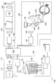
- FIG. 1 is a block diagram illustrating a configuration in a first embodiment of a fundus optical tomographic image generation device according to the present invention.
- FIG. It is a graph regarding the aberration amount of the eyeball in a healthy body, and the aberration order by a Guernike polynomial display. It is the side view (a) and front view (b) of the biaxial galvanometer in 1st Embodiment. It is a figure for demonstrating the calculation method of the interference intensity
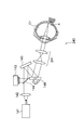
- It is a block diagram which shows the structure in 2nd Embodiment of the optical tomographic image generation device for fundus
- the retinal three-dimensional image generation apparatus of the present invention is applied to a fundus optical tomographic image generation apparatus using an adaptive control optical system (AO).
- AO adaptive control optical system
- the fundus optical tomographic image generation device (100) divides an outgoing light beam emitted from the same light source (111) into an object to be measured as a retina (R) of the eyeball and a reference mirror (RM).
- the compensating optical measurement unit (140) that reflects the light scattered by the retina as an object reflected light beam while compensating for the
- Detection means for detecting the interference intensity for each interfered wavelength, and Fourier transform of the detected interference intensity for each wavelength, thereby substantially parallel to the incident direction of the object light beam of the retina
- Compensation optical measurement unit comprising: calculation means (155) for calculating reflection intensity data in the depth direction; and generation means (155) for generating a three-dimensional image of the retina based on the calculated reflection intensity data.
- (140) is a wavefront sensor (143) for detecting the wavefront of the object reflected light beam, and the object reflected light detected by the wavefront sensor (143).
- Imaging position adjusting means (145, 147 (147a, 147b), 241, 341, 342) for adjusting the imaging position in the object light beam based on the wavefront of the beam, and the retina (R )
- Beam angle adjusting means (146 (146a, 146b, 146c)) for adjusting the angle of the object light beam with respect to the image forming position in order to scan the image forming position above
- the light source unit (110) is configured to irradiate a light beam having a depth of focus of 300 ⁇ m or more and a resolution in a plane direction perpendicular to the traveling direction of the light beam higher than 6 ⁇ m ⁇ 6 ⁇ m.
- the beam angle adjusting means (146 (146a, 146b, 146c)) is substantially parallel to the retina forming surface on which the retina (R) is formed.
- a single scanning mirror movable in two directions to scan the object light beam in a first direction and a second direction substantially parallel to the retinal forming surface and substantially perpendicular to the first direction.
- (146a) and the scanning mirror (146a) includes a galvanometer (146b, 146c) for controlling the movement in each movable direction.
- the imaging position adjusting means (145, 147 (147a, 147b)) is mirror-finished based on the wavefront of the object reflected light beam detected by the wavefront sensor (143).
- a deformable mirror (145) that deforms, and a concave mirror (147 (147a, 147b)) that focuses the object light beam reflected by the deformable mirror (145) on the retina (R). .
- the imaging position adjusting means (145, 241) deforms the mirror surface based on the wavefront of the object reflected light beam detected by the wavefront sensor (143).
- the fundus optical tomographic image generation device (100) has a configuration in which the wavefront of the object reflected light beam is disturbed by moving the mirror surface of the variable mirror (145).
- the imaging position adjusting means (341, 342) is a pair of convex lenses, and the object reflected light beam detected by the wavefront sensor (143) is used.
- FIG. 1 is a block diagram illustrating the configuration of the fundus optical tomographic image generation apparatus 100 according to the present embodiment
- FIG. 2 is a graph relating to the aberration amount of the eyeball in a healthy body and the aberration order based on the Guernike polynomial display.
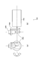
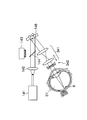
- FIG. 3 is a side view (a) and a front view (b) of the biaxial galvanometer 146 in the first embodiment.
- the fundus optical tomographic image generation apparatus 100 uses an adaptive control optical system (AO) technology and uses an interference effect of light, which is an object to be inspected (in this embodiment, an eyeball EY). Specifically, it is an OCT measurement apparatus that acquires a tomographic image of the retina R).
- AO adaptive control optical system
- the fundus optical tomographic image generation apparatus 100 includes an object scanning light beam (hereinafter also referred to as an “object light beam”) that irradiates an examination target with a light source beam (hereinafter also referred to as an “emitted light beam”). When performing interference measurement, it is divided into a reference light beam which is a standard for the interference measurement. Then, the fundus optical tomographic image generation device 100 includes an object reflected light beam that is reflected when the object scanning light beam is applied to the object, and a reference reflected light beam that is reflected by a predetermined reflector RM. And are designed to interfere with each other.
- object light beam an object scanning light beam
- emitted light beam a light source beam
- the fundus optical tomographic image generation device 100 includes an object reflected light beam that is reflected when the object scanning light beam is applied to the object, and a reference reflected light beam that is reflected by a predetermined reflector RM. And are designed to interfere with each other.
- the fundus optical tomographic image generation device 100 scans the object scanning light beam in a first direction (lateral direction) substantially parallel to the retinal formation surface on which the retina R is formed, and on the retinal formation surface. Scanning is performed in a second direction (longitudinal direction) that is substantially parallel to the first direction and substantially perpendicular to the first direction. Then, the fundus optical tomographic image generation device 100 determines the traveling direction of the object scanning light beam based on the object reflected light beam and the reference reflected light beam interfered at each point (hereinafter also referred to as “scanning point”). A tomographic image of the retina R including the depth direction of the retina R parallel to the (optical axis direction) is generated.
- the fundus optical tomographic image generation apparatus 100 includes a light source unit 110 that irradiates a light source beam, and scans the irradiated light source beam with a reference light beam and object scanning.
- An optical distribution coupler 120 is provided for distributing the light beam to the light beam and interfering the reference reflected light beam and the object reflected light beam.
- the light source unit 110 of the present embodiment constitutes a light source unit of the present invention
- the light distribution coupler 120 constitutes an optical splitter.
- the fundus optical tomographic image generation device 100 reflects the reference light beam and makes the reference reflected light beam, which is the reflected reference light beam, incident on the light distribution coupler 120, and object scanning.
- An inspection unit 140 that irradiates an object with a light beam and makes the object-reflected light beam enter the light distributor / coupler 120; .),
- an image detection unit 150 for acquiring a tomographic image of the object.
- the reference light unit 130 of the present embodiment constitutes a reference light beam unit of the present invention
- the inspection unit 140 constitutes an adaptive optics measurement unit of the present invention.
- the image detection unit 150 of the present embodiment constitutes a detection unit, a calculation unit, and a generation unit of the present invention.
- the light source unit 110 emits light that is temporally incoherent and spatially incoherent.
- the light source unit 110 includes an irradiation light source 111 that irradiates a light source beam and an optical isolator BI.
- the light source beam irradiated from the irradiation light source 111 is subjected to predetermined calibration using glass.
- the irradiation light source 111 is composed of a super luminescence diode, and irradiates a light beam having a wide wavelength width (for example, a wavelength having a width of about 150 nm) as a light source beam, and has a focal depth of 300 ⁇ m or more. And a light source beam having a resolution (azimuth resolution) in the plane direction perpendicular to the traveling direction of the object scanning light beam is higher than 6 ⁇ m ⁇ 6 ⁇ m.
- the wavelength width of the light source beam is independent of the depth of focus, and the wider the width, the better the resolution in the depth direction of the three-dimensional image. However, in consideration of various effects, the wavelength width of the above level is used. ing. Further, the upper limit value of the focal depth is not particularly limited, but a practical range is 400 ⁇ m. This is because an appropriate diagnosis can be performed with a depth of focus of 400 ⁇ m. The range of the azimuth resolution is not particularly limited, but the realistic maximum resolution is limited by the maximum pupil diameter and is 3 ⁇ m ⁇ 3 ⁇ m.
- the irradiation light source 111 of the present embodiment is gentle to the eyes, is not dazzling, and emits a light source beam having an incident aperture of 3.0 mm as a near infrared light source.
- a light source beam having an incident aperture of 3.0 mm an azimuth resolution higher than 6 ⁇ m ⁇ 6 ⁇ m can be obtained on the retina R and a focal point of about 390 ⁇ m can be obtained. Depth can be obtained.
- the incident aperture of the light source beam output from the irradiation light source 111 of the present embodiment is not limited to 3.0 mm, and may be approximately 3 mm.
- the incident aperture that defines the beam diameter depends on the wavelength, resolution, depth of focus, etc. of the light source.For example, the larger the beam diameter, the better the resolution but the smaller the depth of focus, while the smaller the beam diameter. In this case, the resolution is lowered, but the depth of focus is deepened, and the balance is set.
- the object to be measured is the retina of the eyeball, and in this case, it is preferably approximately 3 mm, for example, 2.5 mm to 3.5 mm.
- the light source beam is irradiated with a diameter of about 3 mm if the allowable aberration limit in image quality is used as a criterion. In this case, it is understood that it is sufficient to correct the third order or lower order aberration.
- the retina can be irradiated with a beam having sufficient azimuth resolution and depth of focus by an object-reflected light beam that can represent wavefront aberration by a third-order or lower expression in the Zernike approximation polynomial. Therefore, as will be described later, even if aberration correction is simplified in the inspection unit 140, data with sufficient interference intensity can be obtained.
- the calibration unit 112 includes an optical isolator BI that transmits a light beam only to the light distribution coupler 120 irradiated from the light source unit 110 and does not transmit the opposite light beam, and performs a predetermined calibration with respect to the light source beam.
- the light distributor / coupler 120 divides a light source beam incident by an optical fiber or a beam splitting prism into an object scanning light beam and a reference light beam, and outputs them to the inspection unit 140 and the reference light unit 130, respectively. Yes.
- the optical distribution coupler 120 of this embodiment has a predetermined distribution ratio (for example, a distribution ratio of about 50:50 to 80:20), and divides the incident light source beam based on the distribution ratio. And output to each.
- a predetermined distribution ratio for example, a distribution ratio of about 50:50 to 80:20
- an object reflected light beam reflected by the object of the inspection unit 140 and a reference reflected light beam reflected by the reference light unit 130 are incident on the light distribution coupler 120.
- the light distributor / coupler 120 causes the incident object reflected light beam and reference reflected light beam to interfere with each other, and outputs the interfered interference light beam to the image detection unit 150.
- the light distribution coupler 120 of the present embodiment is based on a predetermined coupling ratio (for example, a distribution ratio of about 50:50 to 80:20), an incident object reflected light beam and a reference reflected light beam based on the coupling ratio.
- the interference light beam combined and interfered is output to the image detection unit 150.
- the reference light unit 130 is basically a unit for generating a reference reflected light beam as a reference in an optical path having the same length as the optical path of the object scanning light (reflected light) beam.
- the optical path in the reference light unit has a slight optical path difference (optical path difference ⁇ described later) based on the depth required for diagnosis in the optical path of the object scanning light (reflected light) beam and the optical source beam. ing.
- the reference light unit 130 includes a first polarization control unit 131 that controls the polarization of the divided reference light beam and the reflected reference reflected light beam, and converts the reference light beam into parallel light. And a first conversion lens 132 that condenses a reference reflected light beam that is parallel light, and a chromatic aberration correction lens 133 that performs chromatic aberration correction.
- the reference light unit 130 condenses the water vial 134 for adjusting chromatic dispersion, the reflecting mirror RM that reflects the reference light beam, and the reference light beam that is parallel light. And a second conversion lens 135 that converts the reference reflected light beam into parallel light.
- the chromatic aberration correction lens 133 and the water vial 134 are provided in order to create an environment in which the object scanning light beam (specifically, the object reflected light beam) in the inspection unit 140 and the passage through the eyeball are simulated. It has been.
- the color difference correction lens and the water vial 134 are for correcting chromatic aberration or chromatic dispersion caused when the eyeball EY is irradiated with a light beam.
- a pseudo inspection unit is used in the reference light unit 130. This is for generating a light beam subjected to chromatic aberration or chromatic dispersion at 140.
- the first polarization control unit 131 polarizes the reflected reference reflected light beam and the reference light beam so as not to interfere with each other.
- the inspection unit 140 detects the wavefront aberration of the light beam such as the distortion of the cornea originally possessed by the eyeball EY and the movement of the eyeball EY during the inspection based on the object reflected light beam, and is detected by the measurement. The detection result is fed back by adjusting the mirror surface of the deformable mirror 145 based on the aberration.
- the inspection unit 140 of the present embodiment includes a second polarization controller 141 that controls the polarization of the divided object scanning light beam and the reflected object reflected light beam, and the divided object scanning light beam. And an inspection unit conversion lens 142 that condenses the object reflected light beam as well as parallel light.
- the inspection unit 140 includes a wavefront sensor 143 that detects the wavefront aberration of the object reflected light beam, a sensor prism 144 that divides the object reflected light beam and makes a part of the beam incident on the wavefront sensor 143, and a deformable mirror. 145, a biaxial galvanometer 146, and a pair of concave mirrors 147.
- the wavefront sensor 143 of the present embodiment constitutes the wavefront sensor of the present invention
- the deformable mirror 145 constitutes the imaging position adjusting means and the deformable mirror of the present invention.
- the concave mirror 147 of this embodiment constitutes the imaging position adjusting means and concave mirror of the present invention
- the biaxial galvanometer 146 constitutes the beam angle adjusting means of the present invention.
- the second polarization control unit 141 polarizes the reflected object reflected light beam and object scanning light beam so as not to interfere with each other.
- the wavefront sensor 143 of the present embodiment is configured by a Shack-Hartmann sensor, and detects wavefront aberration based on a light beam in the middle of the return path of the object reflected light beam reflected by the retina R. ing.
- the deformable mirror 145 is configured such that the shape of the mirror surface is controlled by the wavefront sensor 143, the object scanning light beam converted into parallel light by the conversion lens 142 for inspection unit, and the object reflection reflected by the retina R. The light beam is reflected in each direction.
- the deformable mirror 145 performs a predetermined mirror operation (operation of a mirror surface that gives a slight vibration to the object scanning light beam) to disturb the object scanning light beam under predetermined control. .
- the present embodiment even if the object scanning light beam is disturbed, when the interference intensity is calculated as described later, in the detection process of the CCD or the like of the scanning camera 154, a slight vibration (That is, it is possible to correct fine vibrations in the object reflected light beam. On the other hand, the contrast of speckle noise can be reduced by giving this fine vibration to the object scanning light beam (object reflected light beam).
- the biaxial galvanometer 146 scans an object in a first direction (lateral direction) that is substantially parallel to the retinal formation surface on which the retina R is formed, while reflecting an object scanning light beam under the control of a control unit (not shown). Formed to scan (movable) the light beam and to scan (movable) the object scanning light beam in the second direction (vertical direction) that is substantially parallel to the retina forming surface and substantially perpendicular to the first direction. Has been.
- the biaxial galvanometer 146 of the present embodiment is configured to scan the object scanning light beam in the horizontal and vertical directions of the retinal forming surface in order to scan the object scanning light beam.
- a single scanning mirror 146a movable around the non-optical axis, a first galvanometer 146b for controlling the scanning mirror to move in a first direction corresponding to the lateral direction of the retinal forming surface, and a scanning mirror 146a
- the scanning mirror 146a of the present embodiment constitutes a scanning mirror of the present invention
- the first galvanometer 146b and the second galvanometer 146c constitute a galvanometer of the present invention.
- the entire first galvanometer 146b is rotated.
- the pair of concave mirrors 147 irradiates the object scanning light beam scanned by the biaxial galvanometer 146 to the eyeball EY so as to form an image on the retina R.
- the object-reflected light beam reflected by the retina R enters the light distribution coupler 120 through the reverse path (that is, the return path) described above.
- the image detection unit 150 calculates the interference intensity at each wavelength by extracting each wavelength from the interference light beam for each scanning point (each point scanned in the horizontal and vertical directions of the retina formation surface). Based on the interference intensity of each wavelength, light intensity data in the depth direction (data indicating the reflection distribution rate in the depth direction) is calculated and displayed.
- the difference in the optical path distance from the reference reflected light beam changes depending on the point where the object scanning light beam is reflected inside the retina, and the interference intensity changes for each wavelength.
- the image detection unit 150 of the present embodiment detects the changed interference intensity, and also performs Fourier transform on the interference intensity, which is data in this wavelength region, to convert it into spatial domain data. Data can be calculated.
- the image detection unit 150 of the present embodiment includes an interference light beam that is interfered with by combining the object reflected light beam transmitted from the inspection unit 140 and the reference reflected light beam transmitted from the reference light unit 130. Is entered.
- the image detection unit 150 also includes a third polarization control unit 151 that controls the polarization of the interference light beam, an image detection unit conversion lens 152 that converts the polarized interference light beam into parallel light, and parallel light interference. And a grating unit 153 that splits the light beam for each wavelength.
- the image detection unit 150 calculates the light intensity data based on the detected interference intensity for each wavelength and the scanning camera 154 that detects the interference intensity for each wavelength, and forms a three-dimensional image of the retina R.
- An image generation unit 155 to perform, and a display unit 156 that displays image data that has been converted into a three-dimensional image are provided.
- the scanning camera 154 of the present embodiment constitutes a detection unit of the present invention
- the image generation unit 155 constitutes a calculation unit and a generation unit of the present invention.
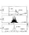
- FIG. 4 is a diagram for explaining a method of calculating the interference intensity between the reference reflected light beam and the object reflected light beam.
- the optical object scanning light beam Ep (t) is light irradiated from the light source unit 110 with s (Z) reflecting and scattering characteristics due to the structure of the retina R with the depth direction of the object, that is, the optical axis direction of the light beam as the z axis. Assuming that the beam (E (t)), it can be expressed by (Equation 1).
- (Expression 1) is expressed by a function of time because the propagation direction of the z-axis and the light beam is the same and the propagation distance is converted to time, so s (z) is a function of time s ( This is because it is expressed by t).
- an optical path difference ( ⁇ ) is given to the reference light unit 130 and the inspection unit 140 in advance, and the optical amplitude signals of the reference reflected light beam and the object reflected light beam entering the optical division coupler are shown in FIG. become that way.
- Equation 2 can be expressed by (Equation 3) based on the correlation calculation (*).
- the first term and the second term on the right side show autocorrelation signals of the reference reflected light beam and the object reflected light beam, and are the central peak in FIG.
- the third and fourth terms on the right side indicate the cross-correlation between the reference reflected light beam and the object reflected light beam, and appear symmetrically at positions separated from the autocorrelation signal.
- E (t) can be regarded as a delta function, so the intensity of this cross-correlation signal is the depth of the object. Due to the reflection / scattering characteristics in the direction, data in the depth direction can be obtained from the interference intensity data without requiring scanning in the depth direction in the spectral region.
- the resolution in the depth direction ( ⁇ z) can be expressed as (Equation 5) using the center wavelength ⁇ and the wavelength width ⁇ of the light source beam.
- ⁇ indicates a wavelength spread width having a Gaussian distribution.
- the fundus optical tomographic image generation device 100 uses an object-reflected light beam that does not include complex aberrations in the cornea or crystalline lens of the eyeball EY, and includes only simple aberrations such as astigmatism. Can be used. That is, the fundus optical tomographic image generation device 100 can use an object reflected light beam that can represent wavefront aberration by a third-order expression or less in the Zernike approximation polynomial, and thus easily correct the aberration. Is possible.
- the fundus optical tomographic image generation device 100 can calculate an accurate interference intensity for each wavelength, and can acquire an accurate three-dimensional image of the retina R based on the calculated reflection intensity data. Therefore, it is possible to maintain high resolution and high operability of the apparatus for the image in the retina R, to reduce the number of parts, and to reduce the size and price.
- the transmittance or reflectance of 100% of the amount of light is difficult, and the amount of light decreases by going through the optical component. Therefore, if the number of components decreases, the loss of light amount decreases. Can also be suppressed.
- the fundus optical tomographic image generation apparatus 100 can scan the object scanning light beam on the retina R by using a single mirror in the biaxial galvanometer 146, thereby reducing the number of components. It is possible to reduce the size and the price.
- the fundus optical tomographic image generation apparatus 100 can use an object reflected light beam that can represent wavefront aberration by a third-order expression or less in the Zernike approximation polynomial. High-order aberrations do not exist and only low-order aberrations are present, and the wavefront aberration in the object reflected light beam can be corrected only by the deformable mirror 145.
- the fundus optical tomographic image generation apparatus 100 of the present embodiment can reduce the contrast of speckle noise by moving the deformable mirror 145 to disturb the wavefront of the body reflected light beam.
- FIG. 5 is a block diagram showing a configuration of the fundus optical tomographic image generation apparatus according to this embodiment.
- the fundus optical tomographic image generation apparatus of the present embodiment is a pair for causing the object scanning light beam scanned by the two-axis galvanometer of the detection unit to enter the eyeball EY and form an image on the retina R.
- a pair of conversion lenses is used, and the other points are the same as in the first embodiment.
- the inspection unit 240 of the present embodiment includes a second polarization control unit 141 that controls the polarization of the divided object scanning light beam and the reflected object reflected light beam, and the inspection unit conversion lens 142.
- the imaging conversion lens 241 of the present embodiment constitutes a convex lens for imaging the object light beam of the present invention on the retina.
- the pair of imaging conversion lenses 241 are a pair of convex lenses so that the object scanning light beam scanned by the biaxial galvanometer 146 is incident on the eyeball EY and irradiated so as to be imaged on the retina R. It has become.
- the fundus optical tomographic image generation device 100 does not include complex aberrations in the cornea or the crystalline lens of the eyeball EY, as in the first embodiment, and simple aberrations such as astigmatism. Only the object reflected light beam included can be used. That is, the fundus optical tomographic image generation device 100 can use an object reflected light beam that can represent wavefront aberration by a third-order expression or less in the Zernike approximation polynomial, and thus easily correct the aberration. Is possible.
- the fundus optical tomographic image generation device 100 can calculate an accurate interference intensity for each wavelength, and can acquire an accurate three-dimensional image of the retina R based on the calculated reflection intensity data. Therefore, it is possible to maintain high resolution and high operability of the apparatus for the image in the retina R, to reduce the number of parts, and to reduce the size and price.
- the transmittance or reflectance of 100% of the amount of light is difficult, and the amount of light decreases by going through the optical component. Therefore, if the number of components decreases, the loss of light amount decreases. Can also be suppressed.
- the fundus optical tomographic image generation apparatus 100 can scan the object scanning light beam on the retina R by using a single mirror in the biaxial galvanometer 146, thereby reducing the number of components. It is possible to reduce the size and the price.
- the fundus optical tomographic image generation device 100 is an object reflected light beam that can represent wavefront aberration by a third-order expression or less in the Zernike approximation polynomial. Since there is no aberration and only low-order aberration, the wavefront aberration in the object reflected light beam can be corrected only by the deformable mirror.
- the fundus optical tomographic image generation apparatus 100 of the present embodiment can reduce the contrast of speckle noise by operating the deformable mirror 145 to disturb the wavefront of the body reflected light beam.
- FIG. 6 is a block diagram showing a configuration of the fundus optical tomographic image generation device according to this embodiment.
- the fundus optical tomographic image generation apparatus uses a conversion lens in which the distance between the lenses is a pair of lenses instead of the deformable mirror and the pair of concave mirrors.
- the other features are the same as in the first embodiment.
- the inspection unit 340 of the present embodiment includes a second polarization control unit 141 that controls the polarization of the divided object scanning light beam and the reflected object reflected light beam, and the inspection unit conversion lens 142.
- the pair of moving lenses 341 according to the present embodiment constitutes a pair of convex lenses according to the present invention
- the lens 342 for image formation adjustment according to the present invention is a lens for forming an object light beam on the retina.
- the pair of moving lenses 341 are cylindrical lenses, and one cylindrical lens, for example, the cylindrical lens on the eyeball EY side moves in the depth direction based on the control of the wavefront sensor 143, and the optical axis of the object scanning light beam is centered. Is supposed to rotate.
- the moving lens 341 performs aberration correction in astigmatism. For example, the moving lens 341 adjusts the distance of the lens based on the direction of the elliptic axis of the elliptical surface that is the wavefront of astigmatism. It has become.
- the imaging adjustment lens 34 for example, a concave lens and a plano-convex lens having a flat single side (eyeball EY side) are used, and an object scanning light beam scanned by the biaxial galvanometer 146 is used for the eyeball. Adjustment is performed so that the light enters the EY and is imaged on the retina R.
- the fundus optical tomographic image generation device 100 does not include complex aberrations in the cornea or the crystalline lens of the eyeball EY, as in the first embodiment, and simple aberrations such as astigmatism. Only the object reflected light beam included can be used. That is, the fundus optical tomographic image generation device 100 can use an object reflected light beam that can represent wavefront aberration by a third-order expression or less in the Zernike approximation polynomial, and thus easily correct the aberration. Is possible.
- the fundus optical tomographic image generation device 100 can calculate an accurate interference intensity for each wavelength, and can acquire an accurate three-dimensional image of the retina R based on the calculated reflection intensity data. Therefore, it is possible to maintain high resolution and high operability of the apparatus for the image in the retina R, to reduce the number of parts, and to reduce the size and price.
- the transmittance or reflectance of 100% of the amount of light is difficult, and the amount of light decreases by going through the optical component. Therefore, if the number of components decreases, the loss of light amount decreases. Can also be suppressed.
- the fundus optical tomographic image generation apparatus 100 can scan the object scanning light beam on the retina R by using a single mirror in the biaxial galvanometer 146, thereby reducing the number of components. It is possible to reduce the size and the price.
- the fundus optical tomographic image generation device 100 is an object reflected light beam that can represent wavefront aberration by a third-order expression or less in the Zernike approximation polynomial. Since there is no aberration and only low-order aberration, the wavefront aberration in the object reflected light beam can be corrected only by the deformable mirror.
Landscapes
- Health & Medical Sciences (AREA)
- Life Sciences & Earth Sciences (AREA)
- Surgery (AREA)
- Biophysics (AREA)
- Ophthalmology & Optometry (AREA)
- Engineering & Computer Science (AREA)
- Biomedical Technology (AREA)
- Heart & Thoracic Surgery (AREA)
- Medical Informatics (AREA)
- Molecular Biology (AREA)
- Physics & Mathematics (AREA)
- Animal Behavior & Ethology (AREA)
- General Health & Medical Sciences (AREA)
- Public Health (AREA)
- Veterinary Medicine (AREA)
- Nuclear Medicine, Radiotherapy & Molecular Imaging (AREA)
- Radiology & Medical Imaging (AREA)
- Eye Examination Apparatus (AREA)
- Investigating Or Analysing Materials By Optical Means (AREA)
- Instruments For Measurement Of Length By Optical Means (AREA)
Abstract
【課題】高分解能を有するとともに、操作性の高く、かつ、小型化および低価格化を図ることができる網膜用3次元画像生成装置を提供する。 【解決手段】眼底用光断層画像生成装置100は、光ソースビームを照射する光源ユニット110と、参照光ビームを反射させる参照光ユニット130と、物体走査光ビームを物体に照射させて反射させる検査ユニット140と、物体反射光ビームと参照反射光ビームを干渉させた干渉光ビームに基づいて物体の断層画像を取得する画像検出ユニット150と、から構成され、光源ユニット110は、例えば、300μm以上の焦点深度を有し、かつ物体走査光ビームの進行方向に垂直な面方向の方位分解能が6μm×6μmより高分解能となる光ビームを照射する。
Description
本発明は、網膜における光学測定用の画像生成装置に関する。
近年、光の干渉効果を利用して生体内部の奥行き構造を可視化する光断層画像生成装置(OCT:Optical Coherence Tomograph)の研究が進んでいる。
特に、最近では、網膜内部の三次元画像の観察することが可能な眼底用光断層画像生成装置も登場し、失明の危険のある疾患の診断にその威力を発揮している。
従来、このような眼底用光断層画像生成装置の一つに、低コヒーレンス干渉計を用いている。そして、このような眼底用光断層画像生成装置は、参照光路長を機械的に操作することによって得られた物体の奥行き方向の干渉信号に基づいて生体内部の奥行き構造を可視化する時間領域眼底用光断層画像生成装置(Time-Domain OCT(以下、「TD-OCT」という。))が知られている。
このTD-OCTは、波長幅の広い低コヒーレンスの光源を有し、当該光源からの光ビームを2つのビームに分割して一のビームを物体(すなわち、眼球)に照射するようになっている。
そして、このTD-OCTは、物体に照射されて走査するためのビーム(以下、「物体走査光ビーム」または「プローブ光ビーム」という。)を、奥行き方向に走査させつつ、分割された他のビームであって参照用としてのビーム(以下、「参照光ビーム」という。)と干渉させる。そして、TD-OCTは、当該干渉により生じた干渉縞に基づいて物体における散乱位置を検出するようになっている。
また、このTD-OCTは、物体に照射した物体走査光ビームを光路に対して横方向に走査させ、または、物体を当該光路に対して横方向に移動させて物体断面の画像を取得するようになっている(例えば、非特許文献1)。
一方、このような機械的な奥行き方向の走査を用いることなく、光波の干渉を実空間(時間領域)で実行する代わりに、フーリエ空間(スペクトル領域)にて実行するスペクトル領域OCT(Fourier Domain OCT(以下、「FD-OCT」という。))が知られている。FD-OCTは、TD-OCTに比べて数十倍の計測速度を有している。
このFD-OCTは、TD-OCTと同様に、分割された2つの光ビームを用いて、かつ、低コヒーレンス干渉原理を用いて物体の奥行き方向の分解能を算出するようになっている。しかしながら、FD-OCTは、参照光ビームおよび物体を走査する物体走査光ビームを平行に分光器に入射させ、当該分光器にて同時に分光させてスペクトル領域で干渉させるようになっている。
また、このFD-OCTは、この干渉により発生したスペクトル干渉縞をCCDによって計測するとともに、当該スペクトル干渉縞に対してフーリエ変換を行うことによって物体の奥行き方向の反射分布を取得するようになっている。
特に、このFD-OCTは、ガルバノミラーを駆動することによって計測点を網膜形成面に対して走査することによって3次元断層画像を取得するようになっており、2次元の機械的走査のみで3次元断層画像を取得することができるので、高速な断層計測を行うことができるようになっている(例えば、非特許文献1)。
なお、上述のOCTの他には、光源の発振波長を掃引して光源の波長を走査して分光器を不要とした波長走査型OCT(Swept Source OCD(以下、「SS-OCT」)という。)というものも知られている(例えば、非特許文献1)。
安野嘉晃、「フーリエドメイン光コヒーレンストモグラフィー」、応用物理、第75巻、第6号、P.707-712(2006)
しかしながら、上述の各方式におけるOCTであっては、画像分解能が十分でないため、加齢黄斑変性や緑内障と言った疾患の初期診断が難しいことがあるとともに、検査時間についても更なる短縮化が求められている。
本発明は、上記問題を解決するためになされたものであって、その目的は、高分解能を有するとともに、操作性の高く、かつ、小型化および低価格化を図ることができる網膜用3次元画像生成装置を提供することにある。
(1)上記課題を解決するため、本発明の網膜用3次元画像生成装置は、同一光源から出射された出射光ビームを分割して眼球の網膜である被測定物と参照鏡とにそれぞれ照射し、前記被測定物で反射した物体光ビームと前記参照鏡で反射した参照光ビームとを重ね合わせて得られた干渉縞のデータから被測定物の3次元画像を生成する網膜用3次元画像生成装置であって、前記光源を有する光源ユニットと、前記光源から出射された出射光ビームを前記参照光ビームと前記物体走査光ビームに分割する光分割器と、前記参照鏡を有し、前記参照光ビームを反射させる参照光ビームユニットと、前記網膜に物体光ビームを照射し、前記眼球の構造に起因して生ずる収差を補償しつつ、当該網膜にて散乱された光を物体反射光ビームとして反射させる補償光学測定ユニットと、前記反射された参照光ビームと前記物体反射光ビームとを干渉させるとともに干渉された波長毎に干渉強度を検出する検出手段と、検出された各波長毎の干渉強度をフーリエ変換することによって前記網膜の前記物体光ビームの入射方向と略平行な奥行き方向における反射強度データを算出する算出手段と、前記算出された反射強度データに基づいて前記網膜の3次元画像を生成する生成手段と、を備え、前記補償光学測定ユニットが、前記物体反射光ビームの波面を検出する波面センサと、前記波面センサにて検出された前記物体反射光ビームの波面に基づいて前記物体光ビームにおける結像位置を調整する結像位置調整手段と、前記物体光ビームによって前記網膜上の結像位置を走査させるために当該物体光ビームの前記結像位置に対する角度を調整するためのビーム角度調整手段と、を有し、前記光源ユニットが、焦点深度が300μm以上であって、光ビームの進行方向に垂直な面方向の分解能が6μm×6μmより高分解能となる光ビームを照射する構成を有している。
例えば、網膜の診断に必要な深度が300μm以上でかつ物体光ビームの進行方向に垂直な面方向の分解能(方位分解能)が6μm×6μmより高分解能となる光ビームを照射すると、眼球の角膜や水晶体などにおける複雑な収差が含まれず、非点収差などの簡単な収差のみ含まれる反射光ビームとなる。言い換えれば、波面収差をゼルニケ近似多項式における3次以下の式にて表すことが可能な反射光ビームとなるので、当該収差を簡単に補正することが可能となる。
本発明の網膜用3次元画像生成装置は、上記構成により、ゼルニケ近似多項式における高次の収差が存在せず、低次の収差のみとなる物体光ビームを用いることができるので、高次の収差を補正するための部品が不要となり、部品点数を少なくすることができるとともに、照射された物体光ビームによって網膜における画像について高分解能および装置の高い操作性を維持することができる。
したがって、本発明の網膜用3次元画像生成装置は、的確な波長毎の干渉強度を算出することができるので、この算出された干渉強度データに基づいて的確な網膜の3次元画像を生成することができるとともに、光量損失の低下の抑制並びに小型化および低価格化を図ることができる。
(2)また、本発明の網膜用3次元画像生成装置は、前記ビーム角度調整手段が、前記網膜が形成さている網膜形成面に対して略平行である第1方向と前記網膜形成面に対して略平行であるとともに前記第1方向に略垂直な第2方向とに前記物体光ビームを走査するために2方向に可動可能な単一の走査用鏡と、前記走査用鏡が各可動方向毎に当該可動を制御するガルバノメータと、を備える構成を有している。
この構成により、本発明の網膜用3次元画像生成装置は、単一の鏡を用いることによって網膜上にて物体光ビームを走査することができるので、部品点数を少なくすることができるとともに、光量損失の低下の抑制並びに小型化および低価格化を図ることができる。
(3)また、本発明の網膜用3次元画像生成装置は、前記結像位置調整手段が、前記波面センサによって検出された前記物体反射光ビームの波面に基づいて鏡面が変形する可変形鏡と、前記可変鏡にて反射された物体光ビームを前記網膜に結像させる凹面鏡と、から構成される。
この構成により、本発明の網膜用3次元画像生成装置は、波面収差をゼルニケ近似多項式における3次以下の式にて表すことが可能な物体反射光ビームを用いることができるので、ゼルニケ近似多項式における高次の収差が存在せず、低次の収差のみによって、かつ、可変形鏡のみによって波面収差を補正することができる物体反射光ビームを用いることができる。
したがって、本発明の網膜用3次元画像生成装置は、部品点数を少なくすることができるとともに、光量損失の低下の抑制並びに小型化および低価格化を図ることができる。
(4)また、本発明の網膜用3次元画像生成装置は、前記結像位置調整手段が、前記波面センサによって検出された前記物体反射光ビームの波面に基づいて鏡面が変形する可変形鏡と、前記可変鏡にて反射された物体光ビームを前記網膜に結像させる凸レンズと、から構成される。
この構成により、本発明の網膜用3次元画像生成装置は、波面収差をゼルニケ近似多項式における3次以下の式にて表すことが可能な物体反射光ビームを用いることができるので、ゼルニケ近似多項式における高次の収差が存在せず、低次の収差のみによって、かつ、可変形鏡のみによって物体反射光ビームにおける波面収差を補正することができる。
したがって、本発明の網膜用3次元画像生成装置は、部品点数を少なくすることができるとともに、光量損失の低下の抑制並びに小型化および低価格化を図ることができる。
(5)また、本発明の網膜用3次元画像生成装置は、前記可変鏡の鏡面を可動して物体反射光ビームの波面のかく乱を行う構成を有している。
この構成により、本発明の網膜用3次元画像生成装置は、可変鏡を稼働して体反射光ビームの波面のかく乱を行うことによってスペックル雑音のコントラストを低減させることができる。
(6)また、本発明の網膜用3次元画像生成装置は、前記結像位置調整手段が、一対の凸レンズであって、前記波面センサによって検出された前記物体反射光ビームの波面に基づいて当該凸レンズ間の距離が変化する凸レンズと、前記一対の凸レンズから出射された物体光ビームを前記網膜に結像させるためのレンズと、から構成される。
この構成により、本発明の網膜用3次元画像生成装置は、波面収差をゼルニケ近似多項式における3次以下の式にて表すことが可能な物体反射光ビームを用いることができるので、ゼルニケ近似多項式における高次の収差が存在せず、低次の収差のみによって、かつ、対の凸レンズ間における距離を変化させるのみによって物体反射光ビームにおける波面収差を補正することができる。
したがって、本発明の網膜用3次元画像生成装置は、部品点数を少なくすることができるとともに、光量損失の低下の抑制並びに小型化および低価格化を図ることができる。
本発明の網膜用3次元画像生成装置は、上記構成により、ゼルニケ近似多項式における高次の収差が存在せず、低次の収差のみとなる物体光ビームを用いることができるので、高次の収差を補正するための部品が不要となり、部品点数を少なくすることができるとともに、照射された物体光ビームによって網膜における画像について高分解能および装置の高い操作性を維持することができる。
したがって、本発明の網膜用3次元画像生成装置は、的確な波長毎の干渉強度を算出することができるので、この算出された干渉強度データに基づいて的確な網膜の3次元画像を生成することができるとともに、光量損失の低下の抑制並びに小型化および低価格化を図ることができる。
以下に説明する実施形態は、適応制御光学システム(AO)を用いた眼底用光断層画像生成装置について本発明の網膜用3次元画像生成装置を適用したものである。
特に、眼底用光断層画像生成装置(100)は、同一光源(111)から出射された出射光ビームを分割して眼球の網膜(R)である被測定物と参照鏡(RM)とにそれぞれ照射し、前記被測定物で反射した物体光ビームと前記参照鏡(RM)で反射した参照光ビームとを重ね合わせて得られた干渉縞のデータから被測定物の3次元画像を生成する眼底用光断層画像生成装置(100)であって、前記光源(111)を有する光源ユニット(110)と、前記光源から出射された出射光ビームを前記参照光ビームと前記物体走査光ビームに分割する光分割器(120)と、前記参照鏡(RM)を有し、前記参照光ビームを反射させる参照光ビームユニット(130)と、前記網膜(R)に物体光ビームを照射し、前記眼球の構造に起因して生ずる収差を補償しつつ、当該網膜にて散乱された光を物体反射光ビームとして反射させる補償光学測定ユニット(140)と、前記反射された参照光ビームと前記物体反射光ビームとを干渉させるとともに干渉された波長毎に干渉強度を検出する検出手段(154)と、検出された各波長毎の干渉強度をフーリエ変換することによって前記網膜(R)の前記物体光ビームの入射方向と略平行な奥行き方向における反射強度データを算出する算出手段(155)と、前記算出された反射強度データに基づいて前記網膜の3次元画像を生成する生成手段(155)と、を備え、前記補償光学測定ユニット(140)が、前記物体反射光ビームの波面を検出する波面センサ(143)と、前記波面センサ(143)にて検出された前記物体反射光ビームの波面に基づいて前記物体光ビームにおける結像位置を調整する結像位置調整手段(145、147(147a、147b)、241、341、342)と、前記物体光ビームによって前記網膜(R)上の結像位置を走査させるために当該物体光ビームの前記結像位置に対する角度を調整するためのビーム角度調整手段(146(146a、146b、146c))と、を有し、前記光源ユニット(110)が、焦点深度が300μm以上であって、光ビームの進行方向に垂直な面方向の分解能が6μm×6μmより高分解能となる光ビームを照射する構成を有している。
また、眼底用光断層画像生成装置(100)は、前記ビーム角度調整手段(146(146a、146b、146c))が、前記網膜(R)が形成さている網膜形成面に対して略平行である第1方向と前記網膜形成面に対して略平行であるとともに前記第1方向に略垂直な第2方向とに前記物体光ビームを走査するために2方向に可動可能な単一の走査用鏡(146a)と、前記走査用鏡(146a)が各可動方向毎に当該可動を制御するガルバノメータ(146b、146c)と、を備える構成を有している。
また、眼底用光断層画像生成装置は、前記結像位置調整手段(145、147(147a、147b))が、前記波面センサ(143)によって検出された前記物体反射光ビームの波面に基づいて鏡面が変形する可変形鏡(145)と、前記可変鏡(145)にて反射された物体光ビームを前記網膜(R)に結像させる凹面鏡と(147(147a、147b))、から構成される。
また、眼底用光断層画像生成装置(100)は、前記結像位置調整手段(145、241)が、前記波面センサ(143)によって検出された前記物体反射光ビームの波面に基づいて鏡面が変形する可変形鏡(145)と、前記可変鏡(145)にて反射された物体光ビームを前記網膜(R)に結像させる凸レンズと(241)、から構成される。
また、眼底用光断層画像生成装置(100)は、前記可変鏡(145)の鏡面を可動して物体反射光ビームの波面のかく乱を行う構成を有している。
また、眼底用光断層画像生成装置(100)は、前記結像位置調整手段(341、342)が、一対の凸レンズであって、前記波面センサ(143)によって検出された前記物体反射光ビームの波面に基づいて当該凸レンズ間の距離が変化する凸レンズ(341)と、前記一対の凸レンズ(341)から出射された物体光ビームを前記網膜(R)に結像させるためのレンズ(342)と、から構成される。
以下、本発明の実施形態の詳細について、図面を参照しながら説明する。
[第1実施形態]
はじめに、図1~図4の各図を用いて本発明に係る眼底用光断層画像生成装置の第1実施形態について説明する。
はじめに、図1~図4の各図を用いて本発明に係る眼底用光断層画像生成装置の第1実施形態について説明する。
まず、図1~図4の各図を用いて本実施形態の眼底用光断層画像生成装置100の構成について説明する。
なお、図1は、本実施形態における眼底用光断層画像生成装置100の構成を示すブロック図であり、図2は、健康体における眼球の収差量とゲルニケ多項式表示による収差次数に関するグラフである。また、図3は、第1実施形態における2軸ガルバノメータ146の側面図(a)と正面図(b)である。
本実施形態の眼底用光断層画像生成装置100は、適応制御光学システム(AO)技術を用いるとともに、光の干渉効果を利用して検査対象の物体(本実施形態においては眼球EYであり、具体的には、網膜R)の断層画像を取得するOCT測定装置である。
この眼底用光断層画像生成装置100は、光ソースビーム(以下、「出射光ビーム」ともいう。)を検査対象に照射する物体走査光ビーム(以下、「物体光ビーム」ともいう。)と、干渉計測を行う際にその基準となる参照光ビームと、に分割するようになっている。そして、眼底用光断層画像生成装置100は、当該物体走査光ビームが物体に照射されて反射された物体反射光ビームと、参照光ビームが所定の反射鏡RMにて反射された参照反射光ビームと、を干渉させるようになっている。
また、眼底用光断層画像生成装置100は、物体走査光ビームを、網膜Rが形成さている網膜形成面に対して略平行である第1方向(横方向)に走査するとともに、網膜形成面に対して略平行で、かつ、第1方向に略垂直な第2方向(縦方向)に走査するようになっている。そして、眼底用光断層画像生成装置100は、各ポイント(以下、「走査点」ともいう。)毎に干渉された物体反射光ビームと参照反射光ビームに基づいて物体走査光ビームの進行方向(光軸方向)と平行な網膜Rの奥行き方向を含めた網膜Rの断層画像を生成するようになっている。
具体的には、本実施形態の眼底用光断層画像生成装置100は、図1に示すように、光ソースビームを照射する光源ユニット110と、照射された光ソースビームを参照光ビームと物体走査光ビームとに分配するとともに、参照反射光ビームと物体反射光ビームを干渉させる光分配結合器120と、を有している。なお、例えば、本実施形態の光源ユニット110は、本発明の光源ユニットを構成し、光分配結合器120は、光分割器を構成する。
また、この眼底用光断層画像生成装置100は、参照光ビームを反射させ、当該反射された参照光ビームである参照反射光ビームを光分配結合器120に入射させる参照光ユニット130と、物体走査光ビームを物体に照射させて物体反射光ビームを光分配結合器120に入射させる検査ユニット140と、物体反射光ビームと参照反射光ビームを干渉させた光ビーム(以下、「干渉光ビーム」という。)に基づいて物体の断層画像を取得する画像検出ユニット150と、から構成される。なお、例えば、本実施形態の参照光ユニット130は、本発明の参照光ビームユニットを構成し、検査ユニット140は、本発明の補償光学測定ユニットを構成する。また、例えば、本実施形態の画像検出ユニット150は、本発明の検出手段、算出手段及び生成手段を構成する。
光源ユニット110は、時間的にインコヒーレントであり、かつ、空間的にもインコヒーレントである光を出射するようになっている。
例えば、本実施形態の光源ユニット110は、光ソースビームを照射する照射光源111と、光アイソレータBIを有し、照射光源111から照射された光ソースビームに対してガラスを用いて所定のキャリブレーションを行うキャリブレーション部112と、を備えている。
照射光源111は、スーパールミネセンスダイオードにて構成され、波長幅が広い(例えば、150nm程度の幅を有する波長)光ビームを光ソースビームとして照射するようになっており、300μm以上の焦点深度を有し、かつ、物体走査光ビームの進行方向に垂直な面方向の分解能(方位分解能)が6μm×6μmより高分解能となる光ソースビームを照射するようになっている。
なお、光ソースビームの波長幅は、焦点深度には無関係で、幅が広いほど3次元画像の奥行き方向の分解能が向上するが、種々の影響を鑑みて上記程度の波長幅を使うようになっている。また、焦点深度の上限値は、特に限定されないが、現実的な範囲としては400μmとなる。400μmの焦点深度があれば適正な診断を行うことができるからである。また、方位分解能の範囲は、特に限定されてないが、現実的な最高分解能は、瞳孔の最大径で制限され、3μm×3μmである。
例えば、本実施形態の照射光源111は、目に優しく、眩しくなく、かつ、近赤外線の光源として、3.0mmの入射口径を有する光ソースビームを出射するようになっている。照射光源111が、このような3.0mmの入射口径を有する光ソースビームを出射した場合には、網膜R上において6μm×6μmより高分解能の方位分解能を得ることができるとともに、390μm程度の焦点深度を得ることができるようになっている。
なお、本実施形態の照射光源111から出力される光ソースビームの入射口径は、3.0mmに限らず、概ね3mmであればよい。このビーム径を規定する入射口径は、光源の波長、分解能、焦点深度等に依存し、例えば、ビーム径が大きくなれば分解能は良好になるが焦点深度は小さくなり、一方、ビーム径が小さくなれば分解能は低下するが焦点深度は深くなり、これらのバランスをとって設定される。本発明では被測定物が眼球の網膜であり、この場合は概ね3mmであることが好ましく、例えば、2.5mm~3.5mmであればよい。
なお、図2に示すように、健康な人間(健康体)の眼球EYの収差を測定結果においても、画質における許容収差限界を判断基準とすれば、概ね3mmの口径によって光ソースビームが照射された場合には、3次以下の低次の収差を補正すれば良いことがわかる。
このように、本実施形態においては、波面収差をゼルニケ近似多項式における3次以下の式にて表すことが可能な物体反射光ビームによって方位分解能および焦点深度が十分なビームを網膜に照射することができるので、後述するように、検査ユニット140において収差補正を簡単にしても、十分な干渉強度のデータを得ることができるようになっている。
キャリブレーション部112は、光源ユニット110から照射された光分配結合器120にのみ光ビームを伝送し、その逆の光ビームを伝送しない光アイソレータBIを有し、光ソースビームに対して所定のキャリブレーションを行うようになっている。
光分配結合器120は、光ファイバーやビーム分割プリズムなどによって入射された光ソースビームを物体走査光ビームと参照光ビームに分割し、それぞれ、検査ユニット140および参照光ユニット130に出力するようになっている。
例えば、本実施形態の光分配結合器120は、所定の分配比(例えば50:50~80:20程度の分配比)を有しており、入射した光ソースビームを当該分配比に基づいて分割してそれぞれに出力するようになっている。
また、この光分配結合器120には、検査ユニット140の物体にて反射された物体反射光ビームと、参照光ユニット130で反射された参照反射光ビームとが入射されるようになっている。
そして、この光分配結合器120は、入射された物体反射光ビームおよび参照反射光ビームを干渉させ、当該干渉させた干渉光ビームを画像検出ユニット150に出力するようになっている。
例えば、本実施形態の光分配結合器120は、所定の結合比(例えば50:50~80:20程度の分配比)、入射された物体反射光ビームと参照反射光ビームを当該結合比に基づいて結合して干渉させ、当該結合されて干渉された干渉光ビームを画像検出ユニット150に出力するようになっている。
参照光ユニット130は、基本的には、物体走査光(反射光)ビームの光路と同一の長さを有する光路にて基準となる参照反射光ビームを生成するためのユニットである。ただし、実際には、参照光ユニットにおける光路は、物体走査光(反射光)ビームの光路と光ソースビームにおける診断に必要な深度に基づいて若干の光路差(後述する光路差τ)を有している。
具体的には、本実施形態の参照光ユニット130は、分割された参照光ビームおよび反射された参照反射光ビームの偏光を制御する第1偏光制御部131と、参照光ビームを平行光に変換するとともに平行光である参照反射光ビームを集光させる第1変換レンズ132と、色収差補正を行う色収差補正レンズ133と、を有している。
また、この参照光ユニット130は、色分散を調整するためのウォーターバイアル134と、参照光ビームを反射させる反射鏡RMと、平行光である参照光ビームを集光させるとともに、集光されている参照反射光ビームを平行光に変換する第2変換レンズ135と、を有している。
特に、色収差補正レンズ133およびウォーターバイアル134は、検査ユニット140における物体走査光ビーム(具体的には、物体反射光ビーム)と眼球を通過したことと擬似的に同一の環境下を作り出すために設けられている。
通常、これらの色差補正レンズおよびウォーターバイアル134は、眼球EYに光ビームが照射された際に生じる色収差または色分散を補正するためのものであり、参照光ユニット130においては、擬似的に検査ユニット140における色収差または色分散を行った光ビームを生成するためのものである。
なお、第1偏光制御部131は、反射された参照反射光ビームと参照光ビームとを干渉させないためにそれぞれ偏光させるものである。
検査ユニット140は、物体反射光ビームに基づいて眼球EYが元来有している角膜の歪みや検査中の眼球EYの動きなどの光ビームの波面収差を測定しつつ、当該測定によって検出された収差に基づいて可変形ミラー145の鏡面を調整して当該検出結果をフィードバックするようになっている。
具体的には、本実施形態の検査ユニット140は、分割された物体走査光ビームおよび反射された物体反射光ビームの偏光を制御する第2偏光制御部141と、分割された物体走査光ビームを平行光にするとともに物体反射光ビームを集光する検査ユニット用変換レンズ142と、を有している。
また、この検査ユニット140は、物体反射光ビームの波面収差を検出する波面センサ143と、物体反射光ビームを分割してその一部を波面センサ143に入射させるセンサ用プリズム144と、可変形ミラー145と、2軸ガルバノメータ146と、一対の凹面鏡147と、から構成される。なお、例えば、本実施形態の波面センサ143は、本発明の波面センサを構成し、可変形ミラー145は、本発明の結像位置調整手段及び可変形鏡を構成する。また、例えば、本実施形態の凹面鏡147は、本発明の結像位置調整手段及び凹面鏡を構成し、2軸ガルバノメータ146は、本発明のビーム角度調整手段を構成する。
第2偏光制御部141は、第1偏光制御部131と同様に、反射された物体反射光ビームと物体走査光ビームとを干渉させないためにそれぞれ偏光させるものである。
本実施形態の波面センサ143は、シャック・ハルトマンセンサーにて構成されており、網膜Rにて反射された物体反射光ビームの戻り経路の途中の光ビームに基づいて波面収差を検出するようになっている。
可変形ミラー145は、波面センサ143にて鏡面の形状が制御されるようになっており、検査ユニット用変換レンズ142にて平行光になった物体走査光ビームおよび網膜Rで反射された物体反射光ビームをそれぞれの方向に反射するようになっている。
また、この可変形ミラー145は、所定の制御の下に、物体走査光ビームをかく乱させるための所定のミラー動作(物体走査光ビームに微振動を与える鏡面の動作)を行うようになっている。
なお、本実施形態においては、当該物体走査光ビームをかく乱させたとしても、後述するように干渉強度を算出する際に、走査カメラ154のCCDなどの検出工程において物体走査光ビームにおける微振動(すなわち、物体反射光ビームにおける微振動)を補正することが可能である。その一方、この微振動を物体走査光ビーム(物体反射光ビーム)に与えることによってスペックル雑音のコントラストを低減させることができるようになっている。
2軸ガルバノメータ146は、図示しない制御部の制御の下、物体走査光ビームを反射させつつ、網膜Rが形成さている網膜形成面に対して略平行である第1方向(横方向)に物体走査光ビームを走査(可動)し、かつ、網膜形成面に対して略平行であるとともに第1方向に略垂直な第2方向(縦方向)に物体走査光ビームを走査(可動)するように形成されている。
例えば、本実施形態の2軸ガルバノメータ146は、図3(a)および(b)に示すように、物体走査光ビームを走査するために網膜形成面の横方向および縦方向に物体走査光ビームの非光軸を中心に可動可能な単一の走査用ミラー146aと、走査用ミラーが網膜形成面の横方向に対応する第1方向への可動を制御する第1ガルバノメータ146bと、走査用ミラー146aが網膜形成面の縦方向に対応する第2方向への可動を制御する第2ガルバノメータ146cと、有している。なお、例えば、本実施形態の走査用ミラー146aは、本発明の走査用鏡を構成し、第1ガルバノメータ146b及び第2ガルバノメータ146cは、本発明のガルバノメータを構成する。
特に、第2ガルバノメータ146cは、第1ガルバノメータ146bをブランケット146dによって保持し、走査用ミラー146aを回転させるときには、第1ガルバノメータ146b全体を回転させるようになっている。
一対の凹面鏡147は、2軸ガルバノメータ146によって走査された物体走査光ビームを眼球EYに入射させて網膜Rにて結像されるように照射するようになっている。
なお、網膜Rにて反射された物体反射光ビームは、上述の逆の経路(すなわち、戻り経路)を通って光分配結合器120に入射されるようになっている。
画像検出ユニット150は、走査点(網膜形成面の横方向および縦方向に走査される各点)毎に、干渉光ビームから各波長を抽出して各波長における干渉強度を算出するとともに、当該算出された各波長の干渉強度に基づいて奥行き方向の光強度データ(奥行き方向における反射分布率を示すデータ)を演算して表示するようになっている。
通常、網膜内部にて物体走査光ビームが反射した点によって参照反射光ビームとの光路の距離差が変化して波長毎に干渉強度が変化する。
したがって、本実施形態の画像検出ユニット150は、当該変化した干渉強度を検出するとともに、この波長領域のデータである干渉強度をフーリエ変換して空間領域データに変換し、網膜における奥行き方向の光強度データを演算することができるようになっている。
具体的には、本実施形態の画像検出ユニット150には、検査ユニット140から伝送された物体反射光ビームと参照光ユニット130から伝送された参照反射光ビームと結合させて干渉された干渉光ビームが入力されるようになっている。
また、この画像検出ユニット150は、干渉光ビームの偏光を制御する第3偏光制御部151と、偏光された干渉光ビームを平行光に変換する画像検出ユニット用変換レンズ152と、平行光の干渉光ビームを各波長毎に分光するグレーティング部153と、を備えている。
そして、この画像検出ユニット150は、各波長毎の干渉強度を検出する走査カメラ154と、検出された各波長毎の干渉強度に基づいて光強度データを算出して網膜Rの3次元画像化を行う画像生成部155と、3次元画像化された画像データを表示する表示部156と、を備えている。なお、例えば、本実施形態の走査カメラ154は、本発明の検出手段を構成し、画像生成部155は、本発明の算出手段及び生成手段を構成する。
次に、図4を用いて各波長の干渉強度データから網膜Rの深さ方向の光強度データを算出する方法について説明する。
なお、図4は、参照反射光ビームと物体反射光ビームとにおける干渉強度の算出方法を説明するための図である。
光物体走査光ビームEp(t)は、物体の奥行き方向、すなわち、光ビームの光軸方向をz軸として網膜Rの構造による反射散乱特性をs(Z)および光源ユニット110から照射された光ビーム(E(t))とすると、(式1)で表すことができる。
なお、この「○」の中に「×」のがある記号は、コンボリューションを示す。また、(式1)が時間の関数によって表されているのは、z軸と光ビームの伝播方向が同じであり、伝播距離が時間に換算されるためs(z)が時間の関数s(t)で表されるからである。
また、参照光ユニット130と検査ユニット140には、予め光路差(τ)が与えられており、光分割結合器に入る参照反射光ビームと物体反射光ビームの光振幅信号は図4(a)のようになる。
そして、グレーティング部153によって分光されてフーリエ変換された参照反射光ビームおよび物体反射光ビームの光干渉強度、すなわち、スペクトル干渉縞(E(ω)=F[Ep(t)])が走査カメラ154にて検出されることになる(図4(b)参照)。
このとき、干渉信号Iがフーリエ変換されたフーリエ干渉信号F[I]とスペクトル干渉縞の関係は、(式2)に示される。ただし、E*は、複素共役を示す。

また、この(式2)は、相関演算(*)に基づいて(式3)にて表すことができる。

ここで、右辺の第1項と第2項は参照反射光ビームおよび物体反射光ビームの自己相関信号を示し、図4(c)の中央のピークである。また、右辺第3項と第4項は、参照反射光ビームおよび物体反射光ビームの相互相関を示し、自己相関信号に対して離間した位置に左右対称に現れる。
また、右辺第3項(I3項)は、(式1)の関係から(式4)となるが、参照光ビームが平面鏡にて反射して参照反射光ビームとなり、{Er(t)=E(t)}となるので、光源(光ソースビーム)の自己相関関数と光軸方向(いわゆる奥行き方向)の構造のコンボリューションとなる。
すなわち、光ソースビームのパルス幅が十分に短いか、または、スペクトル分布が十分に広い場合に、E(t)はデルタ関数と見なすことができるので、この相互相関信号の強度は、物体の奥行き方向の反射散乱特性となっているため、スペクトル領域においては奥行き方向への走査を必要とせずに、干渉強度のデータによって奥行き方向のデータを得ることができるようになっている。
なお、深さ方向の分解能(Δz)は、光ソースビームの中心波長λと波長幅Δλを用いて(式5)のように表すことができる。ただし、「σ」は、ガウス分布をしている波長広がり幅を示す。

以上のように、本実施形態の眼底用光断層画像生成装置100は、眼球EYの角膜や水晶体などにおける複雑な収差が含まれず、非点収差などの簡単な収差のみ含まれる物体反射光ビームを用いることができる。すなわち、眼底用光断層画像生成装置100は、波面収差をゼルニケ近似多項式における3次以下の式にて表すことが可能な物体反射光ビームを用いることができるので、当該収差を簡単に補正することが可能となる。
したがって、本実施形態の眼底用光断層画像生成装置100は、的確な波長毎の干渉強度を算出することができるとともに、この算出された反射強度データに基づいて的確な網膜Rの3次元画像を生成することができるので、網膜Rにおける画像について高分解能および装置の高い操作性を維持すること、及び、部品点数を少なくすることができるとともに、小型化および低価格化を図ることができる。
また、いずれの光学部品におきましても、光量の100%の透過率または反射率は難しく、光学部品を経由すればそれだけ光量が減少することとなるので、部品点数が少なくなれば、光量損失の低下についても抑制することができる。
特に、本実施形態の眼底用光断層画像生成装置100は、2軸ガルバノメータ146において単一の鏡を用いることによって網膜R上にて物体走査光ビームを走査することができるので、部品点数を少なくすることができるとともに、小型化および低価格化を図ることができる。
また、本実施形態の眼底用光断層画像生成装置100は、波面収差をゼルニケ近似多項式における3次以下の式にて表すことが可能な物体反射光ビームを用いることができるので、ゼルニケ近似多項式における高次の収差が存在せず、低次の収差のみとなり、可変形ミラー145のみによって物体反射光ビームにおける波面収差を補正することができる。
また、本実施形態の眼底用光断層画像生成装置100は、可変形ミラー145を可動して体反射光ビームの波面のかく乱を行うことによってスペックル雑音のコントラストを低減させることができる。
[第2実施形態]
次に、図5を用いて本発明に係る眼底用光断層画像生成装置100の第2実施形態について説明する。
次に、図5を用いて本発明に係る眼底用光断層画像生成装置100の第2実施形態について説明する。
なお、図5は、本実施形態における眼底用光断層画像生成装置の構成を示すブロック図である。
本実施形態の眼底用光断層画像生成装置は、第1実施形態において、検出ユニットの2軸ガルバノメータによって走査された物体走査光ビームを眼球EYに入射させて網膜Rにて結像させるための一対の凹面鏡に代えて、一対の変換レンズを用いる点に特徴があり、その他の点は、第1実施形態と同一である。
なお、第1実施形態と同一の部材については、同一の番号を付してその説明を省略する。
本実施形態の検査ユニット240は、図4に示すように、分割された物体走査光ビームおよび反射された物体反射光ビームの偏光を制御する第2偏光制御部141と、検査ユニット用変換レンズ142と、波面センサ143と、センサ用プリズム144と、可変形ミラー145と、2軸ガルバノメータ146と、一対の結像用変換レンズ241と、から構成される。なお、例えば、本実施形態の結像用変換レンズ241は、本発明の物体光ビームを網膜に結像させるための凸レンズを構成する。
一対の結像用変換レンズ241は、一対の凸レンズであって、2軸ガルバノメータ146によって走査された物体走査光ビームを眼球EYに入射させて網膜Rにて結像されるように照射するようになっている。
以上のように、本実施形態の眼底用光断層画像生成装置100は、第1実施形態と同様に、眼球EYの角膜や水晶体などにおける複雑な収差が含まれず、非点収差などの簡単な収差のみ含まれる物体反射光ビームを用いることができる。すなわち、眼底用光断層画像生成装置100は、波面収差をゼルニケ近似多項式における3次以下の式にて表すことが可能な物体反射光ビームを用いることができるので、当該収差を簡単に補正することが可能となる。
したがって、本実施形態の眼底用光断層画像生成装置100は、的確な波長毎の干渉強度を算出することができるとともに、この算出された反射強度データに基づいて的確な網膜Rの3次元画像を生成することができるので、網膜Rにおける画像について高分解能および装置の高い操作性を維持すること、及び、部品点数を少なくすることができるとともに、小型化および低価格化を図ることができる。
また、いずれの光学部品におきましても、光量の100%の透過率または反射率は難しく、光学部品を経由すればそれだけ光量が減少することとなるので、部品点数が少なくなれば、光量損失の低下についても抑制することができる。
特に、本実施形態の眼底用光断層画像生成装置100は、2軸ガルバノメータ146において単一の鏡を用いることによって網膜R上にて物体走査光ビームを走査することができるので、部品点数を少なくすることができるとともに、小型化および低価格化を図ることができる。
また、本実施形態の眼底用光断層画像生成装置100は、波面収差をゼルニケ近似多項式における3次以下の式にて表すことが可能な物体反射光ビームとなるので、ゼルニケ近似多項式における高次の収差が存在せず、低次の収差のみであるので、可変形鏡のみによって物体反射光ビームにおける波面収差を補正することができる。
また、本実施形態の眼底用光断層画像生成装置100は、可変形ミラー145を稼働して体反射光ビームの波面のかく乱を行うことによってスペックル雑音のコントラストを低減させることができる。
[第3実施形態]
次に、図6を用いて本発明に係る眼底用光断層画像生成装置の第3実施形態について説明する。
次に、図6を用いて本発明に係る眼底用光断層画像生成装置の第3実施形態について説明する。
なお、図6は、本実施形態における眼底用光断層画像生成装置の構成を示すブロック図である。
本実施形態の眼底用光断層画像生成装置は、第1実施形態において、可変形ミラーおよび一対の凹面鏡に代えて、一対のレンズであって、当該レンズ間の距離が変化する変換レンズを用いる点に特徴があり、その他の点は、第1実施形態と同一である。
なお、第1実施形態と同一の部材については、同一の番号を付してその説明を省略する。
本実施形態の検査ユニット340は、図5に示すように、分割された物体走査光ビームおよび反射された物体反射光ビームの偏光を制御する第2偏光制御部141と、検査ユニット用変換レンズ142と、波面センサ143と、センサ用プリズム144と、2軸ガルバノメータ146と、一対の移動レンズ341と、結像調整用のレンズ342と、から構成される。なお、例えば、本実施形態の一対の移動レンズ341は、本発明の一対の凸レンズを構成し、結像調整用のレンズ342は、本発明において、物体光ビームを網膜に結像させるためのレンズを構成する。
一対の移動レンズ341は、シリンドリカルレンズであって、波面センサ143の制御に基づいて一のシリンドリカルレンズ、例えば、眼球EY側のシリンドリカルレンズが奥行き方向移動するとともに、物体走査光ビームにおける光軸を中心に回転するになっている。
なお、この移動レンズ341は、非点収差における収差補正を行うようにあっており、例えば、非点収差の波面となる楕円面の当該楕円軸の方向に基づいてレンズの距離を調整するようになっている。
なお、結像調整用のレンズ342は、例えば、凹面レンズと片面(眼球EY側)が平らな平凸レンズとを用いるようになっており、2軸ガルバノメータ146によって走査された物体走査光ビームを眼球EYに入射させて網膜Rにて結像されるように調整を行うようになっている。
以上のように、本実施形態の眼底用光断層画像生成装置100は、第1実施形態と同様に、眼球EYの角膜や水晶体などにおける複雑な収差が含まれず、非点収差などの簡単な収差のみ含まれる物体反射光ビームを用いることができる。すなわち、眼底用光断層画像生成装置100は、波面収差をゼルニケ近似多項式における3次以下の式にて表すことが可能な物体反射光ビームを用いることができるので、当該収差を簡単に補正することが可能となる。
したがって、本実施形態の眼底用光断層画像生成装置100は、的確な波長毎の干渉強度を算出することができるとともに、この算出された反射強度データに基づいて的確な網膜Rの3次元画像を生成することができるので、網膜Rにおける画像について高分解能および装置の高い操作性を維持すること、及び、部品点数を少なくすることができるとともに、小型化および低価格化を図ることができる。
また、いずれの光学部品におきましても、光量の100%の透過率または反射率は難しく、光学部品を経由すればそれだけ光量が減少することとなるので、部品点数が少なくなれば、光量損失の低下についても抑制することができる。
特に、本実施形態の眼底用光断層画像生成装置100は、2軸ガルバノメータ146において単一の鏡を用いることによって網膜R上にて物体走査光ビームを走査することができるので、部品点数を少なくすることができるとともに、小型化および低価格化を図ることができる。
また、本実施形態の眼底用光断層画像生成装置100は、波面収差をゼルニケ近似多項式における3次以下の式にて表すことが可能な物体反射光ビームとなるので、ゼルニケ近似多項式における高次の収差が存在せず、低次の収差のみであるので、可変形鏡のみによって物体反射光ビームにおける波面収差を補正することができる。
100 眼底用光断層画像生成装置
110 光源ユニット
111 照射光源
112 キャリブレーション部
BI 光アイソレータ
120 光分配結合器(光分割器)
130 参照光ユニット(参照光ビームユニット)
131 第1偏光制御部
132 第1変換レンズ
133 色収差補正レンズ
134 ウォーターバイアル
135 第2変換レンズ
RM 反射鏡
140、240、340 検査ユニット(補償光学測定ユニット)
141 第2偏光制御部
142 検査ユニット用変換レンズ
143 波面センサ
144 センサ用プリズム
145 可変形ミラー(結像位置調整手段)
146 2軸ガルバノメータ(ビーム角度調整手段)
146a 走査用鏡
146b 第1ガルバノメータ
146c 第2ガルバノメータ
146d ブランケット
147(147a,147b) 凹面鏡(結像位置調整手段)
EY 眼球
R 網膜
150 画像検出ユニット
151 第3偏光制御部
152画像検出ユニット用変換レンズ
153 グレーティング部
154 走査カメラ(検出手段)
155 画像生成部(算出手段、生成手段)
156 表示部
241 結像用変換レンズ(結像位置調整手段)
341 一対の移動レンズ(結像位置調整手段)
342 結像調整用のレンズ(結像位置調整手段)
Claims (6)
- 同一光源から出射された出射光ビームを分割して眼球の網膜である被測定物と参照鏡とにそれぞれ照射し、前記被測定物で反射した物体光ビームと前記参照鏡で反射した参照光ビームとを重ね合わせて得られた干渉縞のデータから被測定物の3次元画像を生成する網膜用3次元画像生成装置であって、
前記光源を有する光源ユニットと、
前記光源から出射された出射光ビームを前記参照光ビームと前記物体光ビームに分割する光分割器と、
前記参照鏡を有し、前記参照光ビームを反射させる参照光ビームユニットと、
前記網膜に物体光ビームを照射し、前記眼球の構造に起因して生ずる収差を補償しつつ、当該網膜にて散乱された光を物体反射光ビームとして反射させる補償光学測定ユニットと、
前記反射された参照光ビームと前記物体反射光ビームとを干渉させるとともに干渉された波長毎に干渉強度を検出する検出手段と、
検出された各波長毎の干渉強度をフーリエ変換することによって前記網膜の前記物体光ビームの入射方向と略平行な奥行き方向における反射強度データを算出する算出手段と、
前記算出された反射強度データに基づいて前記網膜の3次元画像を生成する生成手段と、
を備え、
前記補償光学測定ユニットが、
前記物体反射光ビームの波面を検出する波面センサと、
前記波面センサにて検出された前記物体反射光ビームの波面に基づいて前記物体光ビームにおける結像位置を調整する結像位置調整手段と、
前記物体光ビームによって前記網膜上の結像位置を走査させるために当該物体光ビームの前記結像位置に対する角度を調整するためのビーム角度調整手段と、
を有し、
前記光源ユニットが、焦点深度が300μm以上であって、出射光ビームの進行方向に垂直な面方向の分解能が6μm×6μmより高分解能となる出射光ビームを照射することを特徴とする網膜用3次元画像生成装置。 - 請求項1に記載の網膜用3次元画像生成装置において、
前記ビーム角度調整手段が、
前記網膜が形成さている網膜形成面に対して略平行である第1方向と前記網膜形成面に対して略平行であるとともに前記第1方向に略垂直な第2方向とに前記物体光ビームを走査するために2方向に可動可能な単一の走査用鏡と、
前記走査用鏡が各可動方向毎に当該可動を制御するガルバノメータと、
を備えることを特徴とする網膜用3次元画像生成装置。 - 請求項1または2に記載の網膜用3次元画像生成装置において、
前記結像位置調整手段が、
前記波面センサによって検出された前記物体反射光ビームの波面に基づいて鏡面が変形する可変形鏡と、
前記可変鏡にて反射された物体光ビームを前記網膜に結像させる凹面鏡と、
から構成されることを特徴とする網膜用3次元画像生成装置。 - 請求項1または2に記載の網膜用3次元画像生成装置において、
前記結像位置調整手段が、
前記波面センサによって検出された前記物体反射光ビームの波面に基づいて鏡面が変形する可変形鏡と、
前記可変鏡にて反射された物体光ビームを前記網膜に結像させる凸レンズと、
から構成されることを特徴とする網膜用3次元画像生成装置。 - 請求項3または4に記載の網膜用3次元画像生成装置において、
前記可変鏡の鏡面を可動して物体反射光ビームの波面のかく乱を行うことを特徴とする網膜用3次元画像生成装置 - 請求項1または2に記載の網膜用3次元画像生成装置において、
前記結像位置調整手段が、
一対の凸レンズであって、前記波面センサによって検出された前記物体反射光ビームの波面に基づいて当該凸レンズ間の距離が変化する凸レンズと、
前記一対の凸レンズから出射された物体光ビームを前記網膜に結像させるためのレンズと、
から構成されることを特徴とする網膜用3次元画像生成装置。
Priority Applications (3)
| Application Number | Priority Date | Filing Date | Title |
|---|---|---|---|
| JP2011525887A JP5624040B2 (ja) | 2009-08-04 | 2010-08-03 | 網膜用3次元画像生成装置 |
| EP10806436.1A EP2462862A4 (en) | 2009-08-04 | 2010-08-03 | DEVICE FOR GENERATING THREE-DIMENSIONAL PICTURES OF THE NETWORK SKIN |
| US13/388,075 US9039175B2 (en) | 2009-08-04 | 2010-08-03 | Three-dimensional retina image generation device |
Applications Claiming Priority (2)
| Application Number | Priority Date | Filing Date | Title |
|---|---|---|---|
| JP2009-181893 | 2009-08-04 | ||
| JP2009181893 | 2009-08-04 |
Publications (1)
| Publication Number | Publication Date |
|---|---|
| WO2011016437A1 true WO2011016437A1 (ja) | 2011-02-10 |
Family
ID=43544332
Family Applications (1)
| Application Number | Title | Priority Date | Filing Date |
|---|---|---|---|
| PCT/JP2010/063057 Ceased WO2011016437A1 (ja) | 2009-08-04 | 2010-08-03 | 網膜用3次元画像生成装置 |
Country Status (4)
| Country | Link |
|---|---|
| US (1) | US9039175B2 (ja) |
| EP (1) | EP2462862A4 (ja) |
| JP (1) | JP5624040B2 (ja) |
| WO (1) | WO2011016437A1 (ja) |
Cited By (6)
| Publication number | Priority date | Publication date | Assignee | Title |
|---|---|---|---|---|
| JP2013019812A (ja) * | 2011-07-12 | 2013-01-31 | Utsunomiya Univ | 偏光解析システム |
| JP2013090903A (ja) * | 2011-10-06 | 2013-05-16 | Canon Inc | 光断層画像撮像装置 |
| WO2013141229A1 (ja) | 2012-03-21 | 2013-09-26 | 国立大学法人宇都宮大学 | 網膜用3次元画像生成装置 |
| JP2016500530A (ja) * | 2012-10-12 | 2016-01-14 | ソルラブス、インコーポレイテッド | コンパクトで低分散および低収差の補償光学走査システム |
| JP2018158153A (ja) * | 2018-07-06 | 2018-10-11 | 株式会社トプコン | 眼科撮影装置 |
| US11161142B2 (en) | 2013-07-18 | 2021-11-02 | Lisa Marie Evans | System and method for application of a surface compound |
Families Citing this family (12)
| Publication number | Priority date | Publication date | Assignee | Title |
|---|---|---|---|---|
| US8960909B2 (en) * | 2012-01-20 | 2015-02-24 | Canon Kabushiki Kaisha | Control apparatus and control method |
| JP6071331B2 (ja) * | 2012-08-27 | 2017-02-01 | キヤノン株式会社 | 画像処理装置及び画像処理方法 |
| US9913580B2 (en) | 2013-09-19 | 2018-03-13 | Canon Kabushiki Kaisha | Apparatus, method, and non-transitory medium for optical stabilization and digital image registration in scanning light ophthalmoscopy |
| JP6429464B2 (ja) * | 2014-02-25 | 2018-11-28 | キヤノン株式会社 | 偏光oct装置及びその制御方法 |
| US9775514B2 (en) | 2015-02-26 | 2017-10-03 | Canon Kabushiki Kaisha | Apparatus for measurement of a fundus comprising a focusing system and a wavefront correction device |
| US10788309B2 (en) * | 2016-04-01 | 2020-09-29 | The University Of Liverpool | Frequency-domain optical interferometry imaging apparatus and method for astigmatistic bi-focal illumination imaging of an eye |
| US10452138B1 (en) * | 2017-01-30 | 2019-10-22 | Facebook Technologies, Llc | Scanning retinal imaging system for characterization of eye trackers |
| US10761602B1 (en) | 2017-03-14 | 2020-09-01 | Facebook Technologies, Llc | Full field retinal imaging system for characterization of eye trackers |
| JP7050282B2 (ja) * | 2017-12-22 | 2022-04-08 | 株式会社トーメーコーポレーション | 光断層画像撮影装置及びそれに用いる光源装置 |
| WO2020033920A1 (en) * | 2018-08-09 | 2020-02-13 | The Regents Of The University Of California | Apparatus and methods for speckle reduction and structure extraction in optical coherence tomography |
| US12440100B2 (en) * | 2020-05-29 | 2025-10-14 | University Of Tsukuba | Image generation device, program, and image generation method |
| WO2026021821A1 (en) * | 2024-07-25 | 2026-01-29 | Centervue S.P.A. | Apparatus for acquiring images by optical coherence tomography |
Citations (7)
| Publication number | Priority date | Publication date | Assignee | Title |
|---|---|---|---|---|
| JP2001507258A (ja) * | 1996-12-23 | 2001-06-05 | ユニヴァースティ オブ ロチェスター | 視力及び網膜画像解像改善装置 |
| JP2006250826A (ja) * | 2005-03-11 | 2006-09-21 | Yamagata Prefecture | 計測素子、加工装置および計測方法、屈折率の計測素子 |
| JP2007521866A (ja) * | 2004-01-22 | 2007-08-09 | セントレ ナショナル デ ラ レチャーチェ シャーティフィック | 網膜の高解像側方及び軸位断層画像化 |
| US20080049232A1 (en) * | 2006-08-25 | 2008-02-28 | The General Hospital Coporation | Apparatus and methods for enhancing optical coherence tomography imaging using volumetric filtering techniques |
| JP2009504294A (ja) * | 2005-08-18 | 2009-02-05 | イマジン アイズ | 眼科学機器に適用される眼の収差を補正する方法及びシステム |
| JP2009524066A (ja) * | 2006-01-20 | 2009-06-25 | ザ ジェネラル ホスピタル コーポレイション | 波面変調を使用してスペックル低減を提供する光学的干渉断層撮影法のシステム、構成、及びプロセス |
| JP2009142313A (ja) * | 2007-12-11 | 2009-07-02 | Tomey Corporation | 前眼部光干渉断層撮影装置及び前眼部光干渉断層撮影方法 |
Family Cites Families (4)
| Publication number | Priority date | Publication date | Assignee | Title |
|---|---|---|---|---|
| JP4157839B2 (ja) | 2001-08-30 | 2008-10-01 | ユニバーシティー オブ ロチェスター | 生体眼の網膜領域撮像方法及びそのシステム |
| DE10360570B4 (de) * | 2003-12-22 | 2006-01-12 | Carl Zeiss | Optisches Meßsystem und optisches Meßverfahren |
| JP4653577B2 (ja) * | 2005-07-08 | 2011-03-16 | 株式会社ニデック | 眼科撮影装置 |
| US7791734B2 (en) * | 2006-05-02 | 2010-09-07 | Lawrence Livermore National Security, Llc | High-resolution retinal imaging using adaptive optics and Fourier-domain optical coherence tomography |
-
2010
- 2010-08-03 JP JP2011525887A patent/JP5624040B2/ja not_active Expired - Fee Related
- 2010-08-03 US US13/388,075 patent/US9039175B2/en not_active Expired - Fee Related
- 2010-08-03 EP EP10806436.1A patent/EP2462862A4/en not_active Withdrawn
- 2010-08-03 WO PCT/JP2010/063057 patent/WO2011016437A1/ja not_active Ceased
Patent Citations (7)
| Publication number | Priority date | Publication date | Assignee | Title |
|---|---|---|---|---|
| JP2001507258A (ja) * | 1996-12-23 | 2001-06-05 | ユニヴァースティ オブ ロチェスター | 視力及び網膜画像解像改善装置 |
| JP2007521866A (ja) * | 2004-01-22 | 2007-08-09 | セントレ ナショナル デ ラ レチャーチェ シャーティフィック | 網膜の高解像側方及び軸位断層画像化 |
| JP2006250826A (ja) * | 2005-03-11 | 2006-09-21 | Yamagata Prefecture | 計測素子、加工装置および計測方法、屈折率の計測素子 |
| JP2009504294A (ja) * | 2005-08-18 | 2009-02-05 | イマジン アイズ | 眼科学機器に適用される眼の収差を補正する方法及びシステム |
| JP2009524066A (ja) * | 2006-01-20 | 2009-06-25 | ザ ジェネラル ホスピタル コーポレイション | 波面変調を使用してスペックル低減を提供する光学的干渉断層撮影法のシステム、構成、及びプロセス |
| US20080049232A1 (en) * | 2006-08-25 | 2008-02-28 | The General Hospital Coporation | Apparatus and methods for enhancing optical coherence tomography imaging using volumetric filtering techniques |
| JP2009142313A (ja) * | 2007-12-11 | 2009-07-02 | Tomey Corporation | 前眼部光干渉断層撮影装置及び前眼部光干渉断層撮影方法 |
Non-Patent Citations (2)
| Title |
|---|
| See also references of EP2462862A4 |
| YASUNO YOSHIAKI: "Fourier Domain Optical Coherence Tomography", APPLIED PHYSICS, vol. 75, no. 6, 2006, pages 707 - 712 |
Cited By (9)
| Publication number | Priority date | Publication date | Assignee | Title |
|---|---|---|---|---|
| JP2013019812A (ja) * | 2011-07-12 | 2013-01-31 | Utsunomiya Univ | 偏光解析システム |
| EP2733477A4 (en) * | 2011-07-12 | 2015-04-01 | Univ Utsunomiya | ELLIPSOMETRIESYSTEM |
| US9612193B2 (en) | 2011-07-12 | 2017-04-04 | Utsunomiya University | Ellipsometry system |
| JP2013090903A (ja) * | 2011-10-06 | 2013-05-16 | Canon Inc | 光断層画像撮像装置 |
| WO2013141229A1 (ja) | 2012-03-21 | 2013-09-26 | 国立大学法人宇都宮大学 | 網膜用3次元画像生成装置 |
| US9282887B2 (en) | 2012-03-21 | 2016-03-15 | Utsunomiya University | Three-dimensional retina image generator |
| JP2016500530A (ja) * | 2012-10-12 | 2016-01-14 | ソルラブス、インコーポレイテッド | コンパクトで低分散および低収差の補償光学走査システム |
| US11161142B2 (en) | 2013-07-18 | 2021-11-02 | Lisa Marie Evans | System and method for application of a surface compound |
| JP2018158153A (ja) * | 2018-07-06 | 2018-10-11 | 株式会社トプコン | 眼科撮影装置 |
Also Published As
| Publication number | Publication date |
|---|---|
| US20120147326A1 (en) | 2012-06-14 |
| JPWO2011016437A1 (ja) | 2013-01-10 |
| US9039175B2 (en) | 2015-05-26 |
| JP5624040B2 (ja) | 2014-11-12 |
| EP2462862A4 (en) | 2016-11-09 |
| EP2462862A1 (en) | 2012-06-13 |
Similar Documents
| Publication | Publication Date | Title |
|---|---|---|
| JP5624040B2 (ja) | 網膜用3次元画像生成装置 | |
| US10743758B2 (en) | Multiple depth optical coherence tomography system and method and laser eye surgery system incorporating the same | |
| JP6047145B2 (ja) | 網膜用3次元画像生成装置 | |
| JP7620998B2 (ja) | 眼科装置 | |
| CN108135466B (zh) | 相干门控无波前传感器自适应光学多光子显微以及相关系统和方法 | |
| JP6442903B2 (ja) | 眼科装置 | |
| JP5574670B2 (ja) | 補償光学装置、撮像装置および補償光学方法 | |
| JP6411792B2 (ja) | 調節機能評価装置 | |
| JP7368581B2 (ja) | 眼科装置、及び眼科情報処理装置 | |
| JP2019063242A (ja) | Oct装置、および、眼科用画像処理プログラム | |
| JP2022176282A (ja) | 眼科装置、及びその制御方法 | |
| JP5637721B2 (ja) | 断層撮像装置および断層撮像装置の制御装置 | |
| JP7194177B2 (ja) | 前区における光学収差を測定するための位相感応光コヒーレンストモグラフィ | |
| US10357155B2 (en) | Wavefront correction method for adaptive optics system | |
| JP2023040903A (ja) | 眼科装置 | |
| Kwon | The design of high-speed and multi-scale in vivo retinal imaging with wavefront sensorless adaptive optics optical coherence tomography | |
| JP6654657B2 (ja) | 調節機能評価装置 | |
| WO2022176827A1 (ja) | 眼科情報処理装置、眼科装置、眼科情報処理方法、及びプログラム | |
| WO2020166465A1 (ja) | 画像処理装置、画像処理方法、及びプログラム |
Legal Events
| Date | Code | Title | Description |
|---|---|---|---|
| 121 | Ep: the epo has been informed by wipo that ep was designated in this application |
Ref document number: 10806436 Country of ref document: EP Kind code of ref document: A1 |
|
| DPE2 | Request for preliminary examination filed before expiration of 19th month from priority date (pct application filed from 20040101) | ||
| WWE | Wipo information: entry into national phase |
Ref document number: 2011525887 Country of ref document: JP |
|
| NENP | Non-entry into the national phase |
Ref country code: DE |
|
| WWE | Wipo information: entry into national phase |
Ref document number: 13388075 Country of ref document: US |
|
| WWE | Wipo information: entry into national phase |
Ref document number: 2010806436 Country of ref document: EP |