WO2011021422A1 - プリンタ及びプリンタの制御方法 - Google Patents
プリンタ及びプリンタの制御方法 Download PDFInfo
- Publication number
- WO2011021422A1 WO2011021422A1 PCT/JP2010/059015 JP2010059015W WO2011021422A1 WO 2011021422 A1 WO2011021422 A1 WO 2011021422A1 JP 2010059015 W JP2010059015 W JP 2010059015W WO 2011021422 A1 WO2011021422 A1 WO 2011021422A1
- Authority
- WO
- WIPO (PCT)
- Prior art keywords
- bar
- amount
- movement
- drive
- flat bed
- Prior art date
- Legal status (The legal status is an assumption and is not a legal conclusion. Google has not performed a legal analysis and makes no representation as to the accuracy of the status listed.)
- Ceased
Links
Images

Classifications
-
- B—PERFORMING OPERATIONS; TRANSPORTING
- B41—PRINTING; LINING MACHINES; TYPEWRITERS; STAMPS
- B41J—TYPEWRITERS; SELECTIVE PRINTING MECHANISMS, i.e. MECHANISMS PRINTING OTHERWISE THAN FROM A FORME; CORRECTION OF TYPOGRAPHICAL ERRORS
- B41J2/00—Typewriters or selective printing mechanisms characterised by the printing or marking process for which they are designed
- B41J2/005—Typewriters or selective printing mechanisms characterised by the printing or marking process for which they are designed characterised by bringing liquid or particles selectively into contact with a printing material
- B41J2/01—Ink jet
-
- B—PERFORMING OPERATIONS; TRANSPORTING
- B41—PRINTING; LINING MACHINES; TYPEWRITERS; STAMPS
- B41J—TYPEWRITERS; SELECTIVE PRINTING MECHANISMS, i.e. MECHANISMS PRINTING OTHERWISE THAN FROM A FORME; CORRECTION OF TYPOGRAPHICAL ERRORS
- B41J19/00—Character- or line-spacing mechanisms
- B41J19/18—Character-spacing or back-spacing mechanisms; Carriage return or release devices therefor
- B41J19/20—Positive-feed character-spacing mechanisms
-
- B—PERFORMING OPERATIONS; TRANSPORTING
- B41—PRINTING; LINING MACHINES; TYPEWRITERS; STAMPS
- B41J—TYPEWRITERS; SELECTIVE PRINTING MECHANISMS, i.e. MECHANISMS PRINTING OTHERWISE THAN FROM A FORME; CORRECTION OF TYPOGRAPHICAL ERRORS
- B41J19/00—Character- or line-spacing mechanisms
- B41J19/18—Character-spacing or back-spacing mechanisms; Carriage return or release devices therefor
-
- B—PERFORMING OPERATIONS; TRANSPORTING
- B41—PRINTING; LINING MACHINES; TYPEWRITERS; STAMPS
- B41J—TYPEWRITERS; SELECTIVE PRINTING MECHANISMS, i.e. MECHANISMS PRINTING OTHERWISE THAN FROM A FORME; CORRECTION OF TYPOGRAPHICAL ERRORS
- B41J19/00—Character- or line-spacing mechanisms
- B41J19/18—Character-spacing or back-spacing mechanisms; Carriage return or release devices therefor
- B41J19/20—Positive-feed character-spacing mechanisms
- B41J19/202—Drive control means for carriage movement
-
- B—PERFORMING OPERATIONS; TRANSPORTING
- B41—PRINTING; LINING MACHINES; TYPEWRITERS; STAMPS
- B41J—TYPEWRITERS; SELECTIVE PRINTING MECHANISMS, i.e. MECHANISMS PRINTING OTHERWISE THAN FROM A FORME; CORRECTION OF TYPOGRAPHICAL ERRORS
- B41J25/00—Actions or mechanisms not otherwise provided for
- B41J25/001—Mechanisms for bodily moving print heads or carriages parallel to the paper surface
-
- B—PERFORMING OPERATIONS; TRANSPORTING
- B41—PRINTING; LINING MACHINES; TYPEWRITERS; STAMPS
- B41J—TYPEWRITERS; SELECTIVE PRINTING MECHANISMS, i.e. MECHANISMS PRINTING OTHERWISE THAN FROM A FORME; CORRECTION OF TYPOGRAPHICAL ERRORS
- B41J25/00—Actions or mechanisms not otherwise provided for
- B41J25/001—Mechanisms for bodily moving print heads or carriages parallel to the paper surface
- B41J25/003—Mechanisms for bodily moving print heads or carriages parallel to the paper surface for changing the angle between a print element array axis and the printing line, e.g. for dot density changes
-
- B—PERFORMING OPERATIONS; TRANSPORTING
- B41—PRINTING; LINING MACHINES; TYPEWRITERS; STAMPS
- B41J—TYPEWRITERS; SELECTIVE PRINTING MECHANISMS, i.e. MECHANISMS PRINTING OTHERWISE THAN FROM A FORME; CORRECTION OF TYPOGRAPHICAL ERRORS
- B41J25/00—Actions or mechanisms not otherwise provided for
- B41J25/001—Mechanisms for bodily moving print heads or carriages parallel to the paper surface
- B41J25/005—Mechanisms for bodily moving print heads or carriages parallel to the paper surface for serial printing movements superimposed to character- or line-spacing movements
-
- B—PERFORMING OPERATIONS; TRANSPORTING
- B41—PRINTING; LINING MACHINES; TYPEWRITERS; STAMPS
- B41J—TYPEWRITERS; SELECTIVE PRINTING MECHANISMS, i.e. MECHANISMS PRINTING OTHERWISE THAN FROM A FORME; CORRECTION OF TYPOGRAPHICAL ERRORS
- B41J3/00—Typewriters or selective printing or marking mechanisms characterised by the purpose for which they are constructed
- B41J3/28—Typewriters or selective printing or marking mechanisms characterised by the purpose for which they are constructed for printing downwardly on flat surfaces, e.g. of books, drawings, boxes, envelopes, e.g. flat-bed ink-jet printers
Definitions
- the present invention relates to a flat bed type printer having a Y bar that holds a head unit and is movably held with respect to the flat bed, and a control method of the printer.
- This type of flatbed ink jet printer is capable of moving in the transport direction by holding a flatbed on which a medium is placed and a head unit mounted with a head for discharging ink droplets so as to be movable in the scanning direction. And a held Y bar.
- the Y bar is slidably connected to a pair of guide rails provided on both sides of the flat bed, and can be moved in the transport direction by a single motor (drive mechanism).
- the amount of movement of the Y bar in the conveyance direction is calculated by an encoder attached to the motor shaft to control the rotation amount of the motor (for example, Patent Document 1).
- the Y bar becomes long. Therefore, when the Y bar is moved in the conveyance direction, mechanical backlash, expansion / contraction of the drive belt, twisting of the Y bar, and the like occur. In particular, in a large flatbed ink jet printer in which the length of the Y bar exceeds 4 m, the influence is remarkably generated.
- the conventional inkjet printer indirectly calculates the amount of movement of the Y bar, the amount of movement of the Y bar calculated by the encoder attached to the motor shaft and the amount of movement of the actual Y bar There is a problem that an error occurs in the Y-bar and the Y-bar conveyance accuracy decreases.
- the positioning accuracy of the head unit held by the Y bar is lowered, so that the landing position accuracy of the ink droplets ejected from the head unit is lowered, and the print image quality is lowered. End up.
- an object of the present invention is to provide a printer and a printer control method capable of improving the Y bar conveyance accuracy and improving the printing image quality.
- a printer extends in a first direction above a flat bed on which a medium is placed, and holds a head unit that ejects ink droplets so as to be movable in the first direction.
- a Y-bar that is held so as to be movable in a second direction orthogonal to the first direction, and a drive mechanism that transports the Y-bar in the second direction, and drive control of the drive mechanism
- a measurement device that directly measures the amount of movement of the Y bar relative to the flat bed.
- the drive control device controls the amount of control of the drive mechanism based on the amount of movement of the Y bar measured by the measurement device. Correct.
- the ink droplets are ejected from the head unit while moving the head unit in the first direction, and the Y bar is moved in the second direction so that the head unit is placed on the flat bed.
- the actual amount of movement of the Y bar relative to the control amount of the drive mechanism can be obtained by directly measuring the amount of movement of the Y bar relative to the flat bed. Therefore, the Y bar conveyance accuracy can be improved by correcting the control amount of the drive mechanism based on the amount of movement of the Y bar directly measured by the measuring device.
- the landing position accuracy of the ink droplets ejected from the head unit can be improved, so that the print image quality can be improved.
- the drive mechanism includes a first drive mechanism that conveys one end portion in the first direction of the Y bar, and a second drive mechanism that conveys the other end portion in the first direction of the Y bar. It is preferable to provide.
- the Y bar inclination can be adjusted by independently transporting both ends of the Y bar in the first direction by the first drive mechanism and the second drive mechanism. Thereby, even if the Y bar becomes longer in the first direction, the amount of movement of both ends in the first direction of the Y bar can be made uniform, and the inclination of the Y bar can be suppressed.
- a measuring device measures the movement amount of the other end part in the 1st direction of the 1st end of the Y bar in the 1st direction, and the 2nd direction which measures the movement amount of the other end part in the 1st direction of the Y bar. And a measuring device.
- the measuring device preferably includes a linear scale attached to the flat bed and a linear encoder attached to the Y bar to detect the linear scale.
- a linear scale attached to the flat bed
- a linear encoder attached to the Y bar to detect the linear scale.
- the first drive mechanism and the second drive mechanism are driven pulleys and driven pulleys arranged along the second direction, and the timing when they are spanned by the drive pulleys and the driven pulleys and connected to the Y bar. It is preferable to include a belt and a motor that rotates the drive pulley.
- the Y bar is transported using a highly rigid member such as a ball screw.
- a member is expensive and is not satisfactory in terms of cost. Therefore, by adopting simple configurations such as a drive pulley, a driven pulley, a timing belt, and a motor as the first drive mechanism and the second drive mechanism in this way, a member that is less expensive than a member such as a ball screw. Therefore, it is possible to reduce costs while reliably transporting both ends of the Y bar in the first direction in the second direction.
- the printer control method includes a head unit that extends in a first direction above a flat bed on which a medium is placed, and that holds a head unit that ejects ink droplets so as to be movable in the first direction.
- a control method for a printer comprising a Y bar movably held in a second direction orthogonal to the first direction with respect to the flat bed, the conveying step conveying the Y bar in the second direction;
- a measurement step for directly measuring the amount of movement of the Y bar relative to the flat bed, and a correction step for correcting the control amount of the Y bar conveyed in the conveyance step based on the amount of movement of the Y bar measured in the measurement step.
- the ink droplets are ejected from the head unit while the head unit is moved in the first direction, and the Y bar is moved in the second direction. Images can be printed on the placed media.
- the actual amount of movement of the Y bar can be obtained by directly measuring the amount of movement of the Y bar relative to the flat bed. Therefore, the Y bar transport accuracy can be improved by correcting the control amount for transporting the Y bar based on the amount of movement of the Y bar directly measured in the measurement step.
- the landing position accuracy of the ink droplets ejected from the head unit can be improved, so that the print image quality can be improved.
- the conveying step independently conveys one end portion in the first direction of the Y bar and the other end portion in the first direction of the Y bar.
- the inclination of the Y bar can be adjusted by independently transporting both ends of the Y bar in the first direction. For this reason, even if the Y bar becomes longer in the first direction, the amount of movement of both ends in the second direction of the Y bar can be made uniform, and the inclination of the Y bar can be suppressed.
- the measurement step independently measures the amount of movement of one end in the first direction of the Y bar and the amount of movement of the other end in the first direction of the Y bar.
- the tilt of the Y bar can be detected with higher accuracy, and the tilt of the Y bar can be corrected with higher accuracy. Can do.
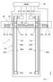
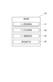
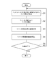
- FIG. 1 is a schematic perspective view showing an ink jet printer according to an embodiment. It is a schematic plan view which shows the function structure of the inkjet printer shown in FIG. It is a block diagram which shows the function structure of a control part. It is a flowchart which shows the processing operation of a control part.
- FIG. 1 is a schematic perspective view showing an ink jet printer according to the embodiment
- FIG. 2 is a schematic plan view showing a functional configuration of the ink jet printer shown in FIG.
- the inkjet printer 1 includes a flat bed 10 on which a medium to be printed (not shown) is placed and fixed, and a Y bar 30 on which a head unit 20 that ejects ink droplets is mounted.
- the ink jet printer 1 moves the head unit 20 in the scanning direction while the medium is placed and fixed on the flat bed 10, and conveys the Y bar 30 in the conveying direction orthogonal to the scanning direction.
- the image is printed on. Therefore, the configuration of the inkjet printer 1 will be described in detail below.
- the scanning direction is the Y-axis direction
- the transport direction is the X-axis direction.
- the flat bed 10 is supported at a predetermined height by a base 11 having a frame structure, and a medium is placed on the upper surface of the flat bed 10 to be sucked and fixed. For this reason, the upper surface of the flat bed 10 is formed on a flat surface, and a plurality of suction holes (not shown) to be sucked by a suction device (not shown) are formed.
- the flat bed 10 has a pair of rails 12 on which the Y bar 30 is placed and holds the Y bar 30 so as to be movable in the X-axis direction, and a drive mechanism 40 for transporting the Y bar 30 in the X-axis direction. Is provided.
- the pair of rails 12 includes a first rail 12 a provided at one end (left end in FIG. 2) in the Y-axis direction of the flat bed 10, and the Y-axis direction of the flat bed 10. And a second rail 12b provided at the other end (the right end in FIG. 2). That is, the Y bar 30 is held by the first rail 12a and the second rail 12b at both ends of the flat bed 10 in the Y-axis direction.
- the drive mechanism 40 includes a first drive mechanism 40a provided at one end of the flat bed 10 in the Y-axis direction, a second drive mechanism 40b provided at the other end of the flat bed 10 in the Y-axis direction, It is comprised by.
- the first drive mechanism 40a includes a drive pulley 41a and a driven pulley 42a arranged along the X-axis direction, a timing belt 43a spanned between the drive pulley 41a and the driven pulley 42a, and a rotation shaft of the drive pulley 41a. And a drive motor 44a that rotates and drives the drive pulley 41a.
- the timing belt 43a is connected to one end (the left end in FIG. 2) in the Y-axis direction of the Y bar 30.
- This timing belt 43a employs a highly rigid timing belt mainly composed of carbon, and the expansion / contraction rate is kept low.
- the drive motor 44a and the drive pulley 41a are connected via an attenuator (not shown) having a predetermined attenuation ratio.
- the second drive mechanism 40b includes a drive pulley 41b and a driven pulley 42b arranged along the X-axis direction, a timing belt 43b spanned between the drive pulley 41b and the driven pulley 42b, and a rotation shaft of the drive pulley 41b. And a drive motor 44b that is connected and rotationally drives the drive pulley 41b.
- the timing belt 43b is connected to the other end (the right end in FIG. 2) in the Y-axis direction of the Y bar 30.
- the timing belt 43b employs a highly rigid timing belt mainly composed of carbon, and the expansion / contraction rate is kept low.
- the drive motor 44b and the drive pulley 41b are connected via an attenuator (not shown) having a predetermined attenuation ratio.
- the 1st drive mechanism 40a and the 2nd drive mechanism 40b are the same structures, Comprising: It is axisymmetric with respect to the centerline which passes along the center in the Y-axis direction of the flat bed 10, and extends in the X-axis direction. Has been. As a result, the Y bar 30 can be transported in the X-axis direction while maintaining a good balance in the Y-axis direction.
- a linear scale 50a disposed along the timing belt 43a of the first drive mechanism 40a and a linear scale 50b disposed along the timing belt 43b of the second drive mechanism 40b are attached to the flat bed 10. It has been.
- the linear scale 50a is attached to one end portion in the Y-axis direction of the flat bed 10, and the movement of one end portion in the Y-axis direction of the Y bar 30 is performed by an optical linear encoder 51a mounted on the Y bar 30 described later. It is a scale for measuring quantities. For this reason, the linear scale 50a is formed in a long band shape extending in the X-axis direction, and slits are formed at a pitch of several to several tens of ⁇ m.
- the linear scale 50b is attached to the other end portion in the Y-axis direction of the flat bed 10, and the other end portion in the Y-axis direction of the Y bar 30 is moved by an optical linear encoder 51b mounted on the Y bar 30 described later. It is a scale for measuring quantities. For this reason, the linear scale 50b is formed in a long band shape extending in the X-axis direction, and slits are formed at a pitch of several to several tens of ⁇ m.
- the linear scale 50a and the linear scale 50b have the same configuration and are symmetrical with respect to the center line of the flat bed 10 in the Y-axis direction. Thereby, it is possible to measure the movement amount of both ends of the Y bar 30 in the Y-axis direction under substantially the same conditions.
- the Y bar 30 is supported by the first rail 12a and the second rail 12b of the flat bed 10 so as to be movable in the X-axis direction, conveys the head unit 20 in the Y-axis direction, and It is conveyed in the X-axis direction.
- the Y bar 30 includes a first roller 31a that is guided by the first rail 12a and rolls in the X-axis direction, a second roller 31b that is guided by the second rail 12b and rolls in the X-axis direction, and the head unit 20 And a head unit driving mechanism 33 for transporting the head unit 20 along the slider shaft 32 in the Y-axis direction.
- the head unit drive mechanism 33 has the same configuration as the first drive mechanism 40a and the second drive mechanism 40b described above, and includes a drive pulley 34 and a driven pulley 35 arranged along the Y-axis direction, A timing belt 36 that is stretched around a driven pulley 35 and connected to the head unit 20, and a drive motor 37 that rotationally drives the drive pulley 34.
- the head unit drive mechanism 33 rotates the drive motor 37
- the drive pulley 34 connected to the drive shaft of the drive motor 37 rotates, and the timing when the drive pulley 34 and the driven pulley 35 are spanned.
- the belt 36 rotates, the head unit 20 is pulled in the Y-axis direction.
- the Y bar 30 is provided with an optical linear encoder 51a disposed at an upper position facing the linear scale 50a, and an optical linear encoder 51b disposed at an upper position facing the linear scale 50b. Yes.
- the optical linear encoder 51a is an encoder (measuring instrument) that detects a slit formed in the linear scale 50a, and measures the amount of movement of the optical linear encoder 51a relative to the linear scale 50a by counting the slits. It is. For example, by emitting infrared rays from the optical linear encoder 51a and analyzing the waveform of the infrared rays reflected from the linear scale 50a, the slits of the linear scale 50a can be detected and the slits can be counted.
- the linear scale 50a is attached to one end of the flat bed 10 in the Y-axis direction
- the optical linear encoder 51a is attached to one end of the Y bar 30 in the Y-axis direction. 51a directly measures the amount of movement of one end in the Y-axis direction of the Y bar 30 relative to the flat bed 10 by counting the slits formed in the linear scale 50a.
- the optical linear encoder 51b is an encoder (measuring instrument) that detects slits formed in the linear scale 50b, and measures the amount of movement of the optical linear encoder 51b relative to the linear scale 50b by counting the slits. It is. For example, by emitting infrared rays from the optical linear encoder 51b and analyzing the waveform of infrared rays reflected from the linear scale 50b, the slits of the linear scale 50b can be detected and the slits can be counted.
- the linear scale 50b is attached to the other end of the flat bed 10 in the Y-axis direction, and the optical linear encoder 51b is attached to the other end of the Y bar 30 in the Y-axis direction. 51b directly measures the amount of movement of the other end in the Y-axis direction of the Y bar 30 relative to the flat bed 10 by counting the slits formed in the linear scale 50b.
- the inkjet printer 1 is provided with a control unit 60 that performs print control.
- the control unit 60 includes a head unit 20, a drive motor 37 of the head unit drive mechanism 33, a drive motor 44a of the first drive mechanism 40a, a drive motor 44b of the second drive mechanism 40b, an optical linear encoder 51a, It is electrically connected to the optical linear encoder 51b.
- the control unit 60 controls the head unit 20, the drive motor 37, the drive motor 44 a, and the drive motor 44 b to perform print control for printing an image on a medium placed on the flat bed 10. Further, the control unit 60 corrects the control amounts of the drive motor 44a and the drive motor 44b based on the measurement results of the optical linear encoder 51a and the optical linear encoder 51b.
- FIG. 3 is a block diagram illustrating a functional configuration example of the control unit.
- the control unit 60 functions as a head drive control unit 61, an ink discharge control unit 62, a Y bar drive control unit 63, and a control amount correction unit 64.
- the control unit 60 is mainly configured by a computer including a CPU, a ROM, and a RAM, for example. Each function of the control unit 60 described below is realized by reading predetermined computer software on the CPU or RAM and operating it under the control of the CPU.
- the head drive controller 61 controls the drive motor 37 and transports the head unit 20 in the Y-axis direction.
- the ink ejection control unit 62 performs ink ejection control of the head unit 20 and ejects ink droplets from the head unit 20 when the head unit 20 is transported in the Y-axis direction by the head drive control unit 61. is there.
- the Y bar drive control unit 63 The drive control of 44a and the drive control of the drive motor 44b are performed, and the Y bar 30 is conveyed by one pass in the X-axis direction.
- the control amount correcting unit 64 corrects the control amounts of the drive motor 44a and the drive motor 44b by analyzing the measurement results of the optical linear encoder 51a and the optical linear encoder 51b, and controls the Y bar 30 in the Y-axis direction. The amount of movement between the end and the other end is adjusted.
- FIG. 4 is a flowchart showing processing of the control unit.
- the processing operation of the inkjet printer 1 described below is performed under the control of the control unit 60. That is, in the control unit 60, a processing unit (not shown) constituted by a CPU or the like follows a program recorded in a storage device such as a ROM, a head drive control unit 61, an ink ejection control unit 62, and a Y bar drive control unit. The following processing is performed by managing the functions of the control amount correction unit 64 and the like.
- the control unit 60 starts the following process when print data (plotting command) is transferred from the external device to the inkjet printer 1.
- step S1 the control unit 60 discharges ink droplets from the head unit 20 while moving the head unit 20 in the Y-axis direction (step S1). That is, in step S1, the drive control of the drive motor 37 and the ink discharge control of the head unit 20 are performed, and ink droplets are discharged from the head unit 20 while moving the head unit 20 in the Y-axis direction. As a result, an image for one pass is printed on the medium that is adsorbed and fixed to the upper surface of the flat bed 10.
- step S2 conveys the Y bar 30 for one pass in the X-axis direction (step S2). That is, in step S2, the drive control of the drive motor 44a and the drive motor 44b is performed with a control amount necessary for conveying the Y bar 30 for one pass. At this time, drive control of the drive motor 44a and the drive motor 44b is performed based on the control amount corrected in step S4 described later. Then, the rotational drive of the drive motor 44a is transmitted to the drive pulley 41a, the timing belt 43a spanned between the drive pulley 41a and the driven pulley 42a rotates, and one end of the Y bar 30 in the Y-axis direction is in the X-axis direction. Towed by one pass.
- the rotational drive of the drive motor 44b is transmitted to the drive pulley 41b, the timing belt 43b spanned between the drive pulley 41b and the driven pulley 42b rotates, and the other end of the Y bar 30 in the Y-axis direction is the X-axis. It is pulled by one path in the direction. As a result, the entire Y bar 30 is conveyed by one pass in the X-axis direction.
- the optical linear encoder 51a and the optical linear encoder 51b attached to the Y bar 30 detect the slits of the linear scale 50a and the linear scale 50b attached to the flat bed 10 and count the number thereof. is doing.
- step S3 the control unit 60 directly measures the amount of movement of the Y bar 30 (step S3). That is, in step S3, the linear scale 50a and the slits of the linear scale 50b counted by the optical linear encoder 51a and the optical linear encoder 51b when the Y bar 30 is transported by one pass in the X-axis direction in step S2 are counted. Get the value. Then, based on the count value acquired from the optical linear encoder 51a, the amount of movement of one end in the X-axis direction of the Y bar 30 relative to the flat bed 10 is measured.
- the amount of movement of the other end in the X-axis direction of the Y bar 30 relative to the flat bed 10 is measured based on the count value acquired from the optical linear encoder 51b. At this time, the amount of movement of one end of the Y bar 30 in the X-axis direction and the amount of movement of the other end do not always coincide with each other due to torsion of the Y bar 30 or mechanical errors.
- control unit 60 drives the drive motor 44a in step S2 based on the amount of movement of one end and the amount of movement of the other end in the X-axis direction of the Y bar 30 directly measured in step S3. And the control amount for driving the drive motor 44a are corrected (step S4). That is, in step S4, the amount of movement of one end and the amount of movement of the other end in the X-axis direction of the Y bar 30 directly measured in step S3 is determined by the control unit 60 in step S2 so that the Y bar 30 corresponds to one path. Determine if it exists.
- step S3 If the amount of movement of one end in the X-axis direction of the Y bar 30 directly measured in step S3 is not one path transported in step S2, the difference is calculated as a correction value, and in step S2, the drive motor The control amount for driving 44a is corrected. Similarly, if the amount of movement of the other end in the X-axis direction of the Y bar 30 measured directly in step S3 is not one path transported in step S2, the difference is calculated as a correction value, and driving is performed in step S2. The control amount for driving the motor 44b is corrected.
- step S2 of the next cycle the drive motor 44a and the drive motor 44b are driven and controlled by the control amount corrected in step S4, so that one end and the other end of the Y bar 30 in the Y-axis direction are It is transported exactly one pass, and the deviation between the amount of movement of one end of the Y bar 30 in the Y-axis direction and the amount of movement of the other end is eliminated or reduced.
- control unit 60 determines whether or not all the print data transferred from the external device has been printed (step S5).
- step S5 NO
- the control unit 60 returns to step S1 and repeats the above-described steps S1 to S4 again.
- step S5 YES
- the control unit 60 ends the printing process.
- the ink droplets are ejected from the head unit 20 while the head unit 20 is moved in the Y-axis direction, and the Y bar 30 is moved in the X-axis direction.
- an image can be printed on the medium placed on the flat bed 10.
- the actual amount of movement of the Y bar 30 relative to the control amount of the first drive mechanism 40a and the second drive mechanism 40b can be obtained.
- the Y bar 30 is corrected by correcting the control amounts of the first drive mechanism 40a and the second drive mechanism 40b based on the movement amount of the Y bar 30 directly measured by the optical linear encoder 51a and the optical linear encoder 51b.
- the conveyance accuracy can be improved. Thereby, since the landing position accuracy of the ink droplets ejected from the head unit 20 can be improved, the print image quality can be improved.
- the inclination of the Y bar 30 with respect to the Y axis direction is adjusted by independently transporting both ends of the Y bar 30 in the Y axis direction by double driving of the first drive mechanism 40a and the second drive mechanism 40b. be able to.
- the amount of movement of both ends of the Y bar 30 in the Y-axis direction is made uniform, and the inclination of the Y bar 30 is suppressed. can do.
- the inclination of the Y bar 30 can be made more accurate.
- the inclination of the Y bar 30 can be corrected with high accuracy.
- the movement of the Y bar 30 relative to the flat bed 10 is measured by the linear scale 50a and the optical linear encoder 51a, and the linear scale 50b and the optical linear encoder 51b.
- the amount can be detected with high accuracy.
- first drive mechanism 40a and the second drive mechanism 40b are simply configured as a drive pulley 41a and a drive pulley 41b, a driven pulley 42a and a driven pulley 42b, a timing belt 43a and a timing belt 43b, a drive motor 44a and a drive motor 44b.
- a member that is less expensive than a member such as a ball screw so that both ends of the Y bar 30 in the Y-axis direction can be reliably conveyed in the X-axis direction and the cost can be reduced. Can do.
- the movement of the Y bar 30 in the X-axis direction and the movement of the head unit 20 in the Y-axis direction are performed by a belt drive that includes a drive pulley, a driven pulley, a timing belt, and a drive motor.
- a ball screw mechanism including a ball screw, a ball bearing connected to the Y bar 30 or the head unit 20, and a drive motor that rotationally drives the ball screw. May be.
- the measurement of the movement amount of the Y bar 30 in the X-axis direction has been described as being performed by a linear scale and an optical linear encoder.
- a rotary encoder, a magnetic measurement device, a distance measurement It may be performed by a radar or the like.
- a wheel which is a rotary encoder jig, is attached to the Y bar 30 so as to be rotatable around the Y-axis direction, and this wheel is brought into contact with the flat bed 10.
- the outer peripheral surface of the wheel is made of a material having a high friction coefficient so that it does not slip with respect to the flat bed 10.
- the wheel attached to the Y bar 30 rolls on the flat bed 10, and therefore, by detecting the amount of rotation of this wheel, the Y bar 30 in the X-axis direction is detected.
- the amount of movement can be measured directly.
- a magnetic measuring device a magnetic tape on which marks such as a memory are recorded is attached to the flat bed 10, and a magnetic head that reads information recorded on the magnetic tape is attached to the Y bar 30.
- the recording information of the magnetic tape attached to the flat bed 10 is read by the magnetic head attached to the Y bar 30. By detecting this recording information, The amount of movement of the Y bar 30 in the X-axis direction can be directly measured.
- the conveyance to the X-axis direction of the Y bar 30 demonstrated as what employ
- the drive pulley 41a and the drive pulley 41b of the second drive mechanism 40b may be connected by a uniaxial drive shaft, and an interlocking drive system in which the drive shaft is rotationally driven by a single drive motor may be adopted. .
- the movement amount of the Y bar 30 in the X-axis direction is directly measured.
- the movement position of the Y bar 30 in the X-axis direction is directly measured, and the directly measured movement position is measured.
- the amount of movement of the Y bar 30 in the X-axis direction may be calculated.
- the movement amount of the Y bar 30 in the X-axis direction is directly measured.
- the movement position of the Y bar 30 in the X-axis direction is directly measured, and the directly measured movement position is measured.
- the amount of movement of the Y bar 30 in the X-axis direction may be calculated.
- the transport amount of one pass for transporting the Y bar 30 at a time has been described as being fixed.
- the transport amount of one pass is appropriately changed depending on the type of media, the type of ink, and the like. It is good also as what is done.
- the linear scales 50a and 50b have been described as having slits. However, in place of the slits, a mountain-shaped step may be formed.
- the optical linear encoders 51a and 51b count the number of crests formed on the linear scales 50a and 50b, thereby reducing the movement amounts of the optical linear encoders 51a and 51b relative to the linear scales 50a and 50b. It can be measured. Thereby, the movement amount of the one end part in the Y-axis direction of the Y bar 30 with respect to the flat bed 10 can be directly measured.
- timing belts 43a and 43b have been described using carbon as a main component, but any material may be used as long as it is a highly rigid material.
- a cored belt may also be used.
- the present invention can be used as a printer.
- drive motor 44b ... drive motor, 50a ... linear scale, 50b ... Linear scale, 51a ... Optical linear encoder, 51b ... Optical linear encoder 60 ... control unit (drive control device), 61 ... head drive control unit, 62 ... inkjet control unit, 63 ... Y bar drive control unit, 64 ... control amount correction unit.
Landscapes
- Ink Jet (AREA)
- Character Spaces And Line Spaces In Printers (AREA)
Abstract
Description
Claims (8)
- メディアが載置されるフラットベッドの上方において第一の方向に延在し、インク液滴を吐出するヘッドユニットを前記第一の方向に移動可能に保持すると共に、前記フラットベッドに対して前記第一の方向に直交する第二の方向に移動可能に保持されるYバーを備えるプリンタであって、
前記駆動機構の駆動制御を行う駆動制御装置と、
前記Yバーを前記第二の方向に搬送する駆動機構と、
前記フラットベッドに対する前記Yバーの移動量を直接計測する計測装置と、
を備え、
前記駆動制御装置は、前記計測装置により計測された前記Yバーの前記移動量に基づいて、前記駆動機構の制御量を補正する、プリンタ。 - 前記駆動機構は、
前記Yバーの第一の方向における一方端部を搬送する第一の駆動機構と、
前記Yバーの第一の方向における他方端部を搬送する第二の駆動機構と、
を備える、請求項1に記載のプリンタ。 - 前記計測装置は、
前記Yバーの第一の方向における一方端部の移動量を計測する第一の計測装置と、
前記Yバーの第一の方向における他方端部の移動量を計測する第二の計測装置と、
を備える、請求項1又は2に記載のプリンタ。 - 前記計測装置は、
前記フラットベッドに取り付けられたリニアスケールと、
前記Yバーに取り付けられて前記リニアスケールを検出するリニアエンコーダと、
を備える、請求項1~3の何れか1項に記載のプリンタ。 - 前記第一の駆動機構及び前記第二の駆動機構は、
前記第二の方向に沿って配列される駆動プーリ及び従動プーリと、
前記駆動プーリ及び前記従動プーリに掛け渡されて、前記Yバーに連結されるタイミングベルトと、
前記駆動プーリを回転させるモータと、
を備える、請求項2~4の何れか1項に記載のプリンタ。 - メディアが載置されるフラットベッドの上方において第一の方向に延在し、インク液滴を吐出するヘッドユニットを前記第一の方向に移動可能に保持すると共に、前記フラットベッドに対して前記第一の方向に直交する第二の方向に移動可能に保持されるYバーを備えるプリンタの制御方法であって、
前記Yバーを前記第二の方向に搬送する搬送ステップと、
前記フラットベッドに対する前記Yバーの移動量を直接計測する計測ステップと、
前記計測ステップにより計測された前記Yバーの移動量に基づいて、前記搬送ステップにより搬送する前記Yバーの制御量を補正する補正ステップと、
を有する、プリンタの制御方法。 - 前記搬送ステップは、
前記Yバーの第一の方向における一方端部と、前記Yバーの第一の方向における他方端部とを、独立して搬送する、請求項6に記載のプリンタの制御方法。 - 前記計測ステップは、
前記Yバーの第一の方向における一方端部の移動量と、前記Yバーの第一の方向における他方端部の移動量とを、独立して計測する、請求項7に記載のプリンタの制御方法。
Priority Applications (4)
| Application Number | Priority Date | Filing Date | Title |
|---|---|---|---|
| CN201080036649.9A CN102470679B (zh) | 2009-08-20 | 2010-05-27 | 打印机以及打印机的控制方法 |
| EP10809768.4A EP2468521A4 (en) | 2009-08-20 | 2010-05-27 | Printer and method of control of printer |
| US13/390,938 US8783820B2 (en) | 2009-08-20 | 2010-05-27 | Printer and printer control method |
| KR1020127004357A KR101343996B1 (ko) | 2009-08-20 | 2010-05-27 | 프린터 및 프린터의 제어방법 |
Applications Claiming Priority (2)
| Application Number | Priority Date | Filing Date | Title |
|---|---|---|---|
| JP2009191180A JP5778380B2 (ja) | 2009-08-20 | 2009-08-20 | プリンタ及びプリンタの制御方法 |
| JP2009-191180 | 2009-08-20 |
Publications (1)
| Publication Number | Publication Date |
|---|---|
| WO2011021422A1 true WO2011021422A1 (ja) | 2011-02-24 |
Family
ID=43606880
Family Applications (1)
| Application Number | Title | Priority Date | Filing Date |
|---|---|---|---|
| PCT/JP2010/059015 Ceased WO2011021422A1 (ja) | 2009-08-20 | 2010-05-27 | プリンタ及びプリンタの制御方法 |
Country Status (6)
| Country | Link |
|---|---|
| US (1) | US8783820B2 (ja) |
| EP (1) | EP2468521A4 (ja) |
| JP (1) | JP5778380B2 (ja) |
| KR (1) | KR101343996B1 (ja) |
| CN (1) | CN102470679B (ja) |
| WO (1) | WO2011021422A1 (ja) |
Families Citing this family (19)
| Publication number | Priority date | Publication date | Assignee | Title |
|---|---|---|---|---|
| US20140285565A1 (en) * | 2012-05-10 | 2014-09-25 | Yuan Chang | Inkjet printing apparatus and printing method |
| JP6285093B2 (ja) * | 2012-09-07 | 2018-02-28 | 株式会社ミマキエンジニアリング | インクジェットプリンタ及び印刷方法 |
| JP5718393B2 (ja) * | 2013-03-12 | 2015-05-13 | 富士フイルム株式会社 | 画像読取方法および画像読取装置 |
| JP6167600B2 (ja) * | 2013-03-27 | 2017-07-26 | セイコーエプソン株式会社 | 記録装置 |
| CN103522751B (zh) * | 2013-10-18 | 2016-01-20 | 福州星月家居装饰用品有限公司 | 家居装饰用品数码平板打印设备及打印工艺 |
| CN105073428B (zh) * | 2013-12-23 | 2017-05-31 | 北京美科艺数码科技发展有限公司 | 喷墨打印装置及打印方法 |
| TWI542476B (zh) * | 2014-05-16 | 2016-07-21 | Polarizing plate printing equipment | |
| CN104129162B (zh) * | 2014-07-31 | 2015-12-09 | 黑金刚(福建)自动化科技股份公司 | 一种智能标记印线机以及采用该设备的自动化印线工艺 |
| JP6202159B2 (ja) * | 2016-07-25 | 2017-09-27 | セイコーエプソン株式会社 | 液体吐出装置 |
| ES2627761B1 (es) * | 2017-03-01 | 2018-05-08 | Tecglass Sl | Máquina y método de impresión digital multipasada de planchas de vidrio con minimización del recorrido de impresión |
| EP3530473B1 (de) * | 2018-02-22 | 2020-07-15 | Heidelberger Druckmaschinen AG | Druckkopf-justagevorrichtung |
| JP7213060B2 (ja) * | 2018-10-29 | 2023-01-26 | 株式会社ミマキエンジニアリング | カラー立体物製造方法およびカラー立体物製造システム |
| JP2020131564A (ja) * | 2019-02-20 | 2020-08-31 | 株式会社ミマキエンジニアリング | スライド機構およびインクジェットプリンタ |
| JP7208586B2 (ja) * | 2019-02-21 | 2023-01-19 | セイコーエプソン株式会社 | 記録装置 |
| JP7215216B2 (ja) | 2019-02-22 | 2023-01-31 | セイコーエプソン株式会社 | 記録装置及び記録方法 |
| JP7259405B2 (ja) * | 2019-02-28 | 2023-04-18 | カシオ計算機株式会社 | 電子機器、動作方法、及びプログラム |
| JP7469178B2 (ja) * | 2020-08-04 | 2024-04-16 | ローランドディー.ジー.株式会社 | インク吐出装置および印刷システム |
| CN113601986A (zh) * | 2021-08-12 | 2021-11-05 | 诸暨市卓码电子科技有限公司 | 一种可小型化平面打印机 |
| JP7771767B2 (ja) * | 2022-01-14 | 2025-11-18 | セイコーエプソン株式会社 | 記録装置 |
Citations (5)
| Publication number | Priority date | Publication date | Assignee | Title |
|---|---|---|---|---|
| JPH11314421A (ja) * | 1998-05-07 | 1999-11-16 | Nec Yonezawa Ltd | 連続用紙プリンタ |
| JP2001253132A (ja) | 2000-03-10 | 2001-09-18 | Seiko Epson Corp | 制御形態設定方法、及び制御装置 |
| JP2004148745A (ja) * | 2002-10-31 | 2004-05-27 | Seiko Epson Corp | ヘッド移動データ生成方法および印刷方法 |
| JP2006075772A (ja) * | 2004-09-10 | 2006-03-23 | Seiko Epson Corp | フラッシングユニットおよびこれを備えた液滴吐出装置、並びに電気光学装置の製造方法、電気光学装置および電子機器 |
| JP2006224559A (ja) * | 2005-02-21 | 2006-08-31 | Seiko Instruments Inc | インクジェットプリンタ |
Family Cites Families (5)
| Publication number | Priority date | Publication date | Assignee | Title |
|---|---|---|---|---|
| JP3573993B2 (ja) * | 1999-02-16 | 2004-10-06 | シャープ株式会社 | インクジェットプリンタのキャリッジ駆動機構 |
| JP2002292907A (ja) * | 2001-03-30 | 2002-10-09 | Brother Ind Ltd | カラーインクジェット記録装置 |
| US7140711B2 (en) * | 2003-07-21 | 2006-11-28 | 3M Innovative Properties Company | Method and apparatus for inkjet printing using radiation curable ink |
| EP1721751A1 (en) * | 2005-05-09 | 2006-11-15 | Agfa-Gevaert | Reconfigurable printhead table for digital printers |
| US7810894B2 (en) * | 2007-03-29 | 2010-10-12 | Hewlett-Packard Development Company, L.P. | Hybrid printing device |
-
2009
- 2009-08-20 JP JP2009191180A patent/JP5778380B2/ja not_active Expired - Fee Related
-
2010
- 2010-05-27 EP EP10809768.4A patent/EP2468521A4/en not_active Withdrawn
- 2010-05-27 KR KR1020127004357A patent/KR101343996B1/ko not_active Expired - Fee Related
- 2010-05-27 US US13/390,938 patent/US8783820B2/en active Active
- 2010-05-27 WO PCT/JP2010/059015 patent/WO2011021422A1/ja not_active Ceased
- 2010-05-27 CN CN201080036649.9A patent/CN102470679B/zh not_active Expired - Fee Related
Patent Citations (5)
| Publication number | Priority date | Publication date | Assignee | Title |
|---|---|---|---|---|
| JPH11314421A (ja) * | 1998-05-07 | 1999-11-16 | Nec Yonezawa Ltd | 連続用紙プリンタ |
| JP2001253132A (ja) | 2000-03-10 | 2001-09-18 | Seiko Epson Corp | 制御形態設定方法、及び制御装置 |
| JP2004148745A (ja) * | 2002-10-31 | 2004-05-27 | Seiko Epson Corp | ヘッド移動データ生成方法および印刷方法 |
| JP2006075772A (ja) * | 2004-09-10 | 2006-03-23 | Seiko Epson Corp | フラッシングユニットおよびこれを備えた液滴吐出装置、並びに電気光学装置の製造方法、電気光学装置および電子機器 |
| JP2006224559A (ja) * | 2005-02-21 | 2006-08-31 | Seiko Instruments Inc | インクジェットプリンタ |
Non-Patent Citations (1)
| Title |
|---|
| See also references of EP2468521A4 * |
Also Published As
| Publication number | Publication date |
|---|---|
| EP2468521A4 (en) | 2017-01-11 |
| CN102470679B (zh) | 2014-09-17 |
| JP2011042087A (ja) | 2011-03-03 |
| CN102470679A (zh) | 2012-05-23 |
| US8783820B2 (en) | 2014-07-22 |
| JP5778380B2 (ja) | 2015-09-16 |
| KR101343996B1 (ko) | 2013-12-24 |
| KR20120046264A (ko) | 2012-05-09 |
| EP2468521A1 (en) | 2012-06-27 |
| US20120182336A1 (en) | 2012-07-19 |
Similar Documents
| Publication | Publication Date | Title |
|---|---|---|
| JP5778380B2 (ja) | プリンタ及びプリンタの制御方法 | |
| US7478894B2 (en) | Method of calibrating print alignment error | |
| US6179419B1 (en) | Belt driven media handling system with feedback control for improving media advance accuracy | |
| US20040165023A1 (en) | Method of compensating sheet feeding errors in ink-jet printer | |
| US7530657B2 (en) | Media transport encoder accuracy | |
| US8287065B2 (en) | Recording apparatus | |
| WO2011040098A1 (ja) | インクジェット画像記録装置およびベルト搬送補正方法 | |
| JP2011042088A (ja) | プリンタ及びプリンタの制御方法 | |
| JP5311973B2 (ja) | プリンタ | |
| US20130002761A1 (en) | Inkjet recording method and inkjet recording apparatus | |
| US20070064029A1 (en) | Method for determining a printhead gap in an ink jet apparatus that performs bi-directional alignment of the printhead | |
| JP2012088914A (ja) | 印刷装置の製造方法、印刷装置の調整方法、及び、印刷装置 | |
| JP5806577B2 (ja) | 記録装置、制御方法及び計測装置 | |
| JP2008028737A (ja) | 媒体上のパターンの印刷位置の算出方法 | |
| JP2009234023A (ja) | ローラ偏芯度評価方法とこの方法を実施するプリント装置 | |
| JP2007021933A (ja) | 印刷装置 | |
| US20120081447A1 (en) | Transport adjustment method, transport adjustment system, and transport adjustment program | |
| JP2003320718A (ja) | 記録装置および紙送り補正方法 | |
| JP2011005850A (ja) | 画像記録装置、記録位置ずれ量算出方法および測定パターンの記録方法 | |
| JP2019081324A (ja) | インクジェット記録装置 | |
| JP7336216B2 (ja) | 画像記録装置、読取り装置、画像記録方法および記録媒体搬送方法 | |
| JP2008034950A (ja) | 媒体上のパターンの印刷位置の算出方法 | |
| JP2003291476A (ja) | 双方向記録型プリンタの記録位置ずれ補正方法、双方向記録型プリンタ、双方向記録型プリンタの記録位置ずれ補正プログラム | |
| JP2008030234A (ja) | 媒体上のパターンの印刷位置の算出方法 | |
| JP3948341B2 (ja) | 印刷装置、プログラム及びコンピュータシステム |
Legal Events
| Date | Code | Title | Description |
|---|---|---|---|
| WWE | Wipo information: entry into national phase |
Ref document number: 201080036649.9 Country of ref document: CN |
|
| 121 | Ep: the epo has been informed by wipo that ep was designated in this application |
Ref document number: 10809768 Country of ref document: EP Kind code of ref document: A1 |
|
| REEP | Request for entry into the european phase |
Ref document number: 2010809768 Country of ref document: EP |
|
| WWE | Wipo information: entry into national phase |
Ref document number: 2010809768 Country of ref document: EP |
|
| ENP | Entry into the national phase |
Ref document number: 20127004357 Country of ref document: KR Kind code of ref document: A |
|
| NENP | Non-entry into the national phase |
Ref country code: DE |
|
| WWE | Wipo information: entry into national phase |
Ref document number: 13390938 Country of ref document: US |