WO2011021455A1 - 容器セット - Google Patents
容器セット Download PDFInfo
- Publication number
- WO2011021455A1 WO2011021455A1 PCT/JP2010/062046 JP2010062046W WO2011021455A1 WO 2011021455 A1 WO2011021455 A1 WO 2011021455A1 JP 2010062046 W JP2010062046 W JP 2010062046W WO 2011021455 A1 WO2011021455 A1 WO 2011021455A1
- Authority
- WO
- WIPO (PCT)
- Prior art keywords
- container
- containers
- packaging sheet
- cylindrical
- container set
- Prior art date
- Legal status (The legal status is an assumption and is not a legal conclusion. Google has not performed a legal analysis and makes no representation as to the accuracy of the status listed.)
- Ceased
Links
Images



Classifications
-
- B—PERFORMING OPERATIONS; TRANSPORTING
- B65—CONVEYING; PACKING; STORING; HANDLING THIN OR FILAMENTARY MATERIAL
- B65D—CONTAINERS FOR STORAGE OR TRANSPORT OF ARTICLES OR MATERIALS, e.g. BAGS, BARRELS, BOTTLES, BOXES, CANS, CARTONS, CRATES, DRUMS, JARS, TANKS, HOPPERS, FORWARDING CONTAINERS; ACCESSORIES, CLOSURES, OR FITTINGS THEREFOR; PACKAGING ELEMENTS; PACKAGES
- B65D71/00—Bundles of articles held together by packaging elements for convenience of storage or transport, e.g. portable segregating carrier for plural receptacles such as beer cans or pop bottles; Bales of material
- B65D71/06—Packaging elements holding or encircling completely or almost completely the bundle of articles, e.g. wrappers
- B65D71/08—Wrappers shrunk by heat or under tension, e.g. stretch films or films tensioned by compressed articles
-
- B—PERFORMING OPERATIONS; TRANSPORTING
- B65—CONVEYING; PACKING; STORING; HANDLING THIN OR FILAMENTARY MATERIAL
- B65D—CONTAINERS FOR STORAGE OR TRANSPORT OF ARTICLES OR MATERIALS, e.g. BAGS, BARRELS, BOTTLES, BOXES, CANS, CARTONS, CRATES, DRUMS, JARS, TANKS, HOPPERS, FORWARDING CONTAINERS; ACCESSORIES, CLOSURES, OR FITTINGS THEREFOR; PACKAGING ELEMENTS; PACKAGES
- B65D1/00—Rigid or semi-rigid containers having bodies formed in one piece, e.g. by casting metallic material, by moulding plastics, by blowing vitreous material, by throwing ceramic material, by moulding pulped fibrous material or by deep-drawing operations performed on sheet material
- B65D1/02—Bottles or similar containers with necks or like restricted apertures, designed for pouring contents
- B65D1/0223—Bottles or similar containers with necks or like restricted apertures, designed for pouring contents characterised by shape
-
- B—PERFORMING OPERATIONS; TRANSPORTING
- B65—CONVEYING; PACKING; STORING; HANDLING THIN OR FILAMENTARY MATERIAL
- B65D—CONTAINERS FOR STORAGE OR TRANSPORT OF ARTICLES OR MATERIALS, e.g. BAGS, BARRELS, BOTTLES, BOXES, CANS, CARTONS, CRATES, DRUMS, JARS, TANKS, HOPPERS, FORWARDING CONTAINERS; ACCESSORIES, CLOSURES, OR FITTINGS THEREFOR; PACKAGING ELEMENTS; PACKAGES
- B65D71/00—Bundles of articles held together by packaging elements for convenience of storage or transport, e.g. portable segregating carrier for plural receptacles such as beer cans or pop bottles; Bales of material
- B65D71/06—Packaging elements holding or encircling completely or almost completely the bundle of articles, e.g. wrappers
- B65D71/08—Wrappers shrunk by heat or under tension, e.g. stretch films or films tensioned by compressed articles
- B65D71/10—Wrappers shrunk by heat or under tension, e.g. stretch films or films tensioned by compressed articles and provided with inserts
Definitions
- the present invention relates to a container set in which a plurality of containers arranged substantially in a row are connected while being wrapped with a packaging sheet.
- a container set in which a plurality of containers are connected by a packaging sheet, a paper tray or the like is widely known in order to make it easy to carry a plurality of containers or to clarify the relationship between them.
- a container set there are one in which containers individually coated with a packaging sheet are connected using a separate member such as a paper tray, and one in which packaging sheets covering each container are connected to each other.
- a separate member such as a paper tray
- Patent Documents 1-4 Such a type of container set is disclosed in, for example, the following Patent Documents 1-4.
- the container set described in Patent Document 1 is configured by covering each of a plurality of heat-shrinkable sleeves connected to each other on the container and heating the container in this state to shrink the heat-shrinkable sleeve.
- the container set described in Patent Documents 2 to 4 is configured by covering the containers with respective cylindrical sheet materials connected to each other.
- each of the container sets disclosed in Patent Documents 1-4 has a problem that only a barrel-shaped container having a substantially constant cross-sectional shape can be handled.
- containers having a shape having a “neck” partially having a small diameter cannot be connected unless a separate member such as a paper tray is used. As a result, costs and manufacturing labor have occurred.
- an object of the present invention is to provide a container set that can connect a container having a neck with only a packaging sheet without using another member such as a paper tray.
- the container set of the present invention is a container set in which a plurality of containers arranged substantially in a row are connected while being wrapped with a packaging sheet, and each container has a width in the arrangement direction compared to other parts. And a wide plurality of wide portions are vertically aligned with a narrow portion narrower than the wide portion, and the packaging sheet is a tube made of a heat-shrinkable film that is shrunk along the outer shape of each container It has a plurality of parts, and each cylinder part is connected to an adjacent cylinder part in at least a part of the wide part, and is separated from an adjacent cylinder part in at least a narrow part.
- a semi-break line is formed at the connecting portion between the adjacent cylindrical portions to help cutting the connecting portions.
- the band portion further restrains the movement of the plurality of containers by being shrunk in a state of surrounding all of the plurality of containers, and is partially connected to each cylindrical portion, and partially A separate band part.
- the band portion is provided on at least one of the upper side and the lower side of the cylindrical portion.
- the adjacent cylinder portions are partially connected and the other portions are partially separated.
- each cylindrical part can appropriately follow a complicated container shape, and the corresponding container can be appropriately packaged.
- a container having a constriction can be connected only by a packaging sheet.
- FIG. 2 is an AA end view in FIG. 1.
- FIG. 3 is a BB end view in FIG. 1.
- FIG. 8 is a CC end view in FIG. 7.
- FIG. 8 is a DD end view in FIG. 7.
- It is a front view of the container set illustrated as a reference.
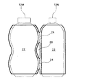
- FIG. 1 is a front view of a container set 10 according to an embodiment of the present invention.
- FIG. 2 is a front view in which a part of the packaging sheet 20 and the container 12 are not shown.
- 3A is a cross-sectional view taken along the line AA in FIG. 1
- FIG. 3B is a cross-sectional view taken along the line BB.
- the dimensions of various members, such as the thickness of the packaging sheet 20 are different from actual.
- the container set 10 of the present embodiment is a plurality of (three in FIG. 1) containers 12 that are packaged and connected by a packaging sheet 20 in a state of being arranged in a row.
- Each of the three connected containers 12 is a hollow body having a lid 14 attached to the upper end, and the inside thereof is filled with a product such as liquid or powder.
- Each container 12 has a substantially gourd shape in which the top and bottom are rounded and the middle is narrowed when viewed from the front. From another point of view, the container 12 handled in the present embodiment has wide portions 16u and 16d (hereinafter, the upper and lower sides) that have a relatively large width in the container arrangement direction (left and right direction in FIG. 1) in the container set 10.
- the subscripts are omitted, and simply “wide portion 16”) are arranged in a row vertically with a narrow portion 18 narrower than the wide portion 16 interposed therebetween.
- the maximum width portion Wmax is a position closest to each adjacent container 12 when the containers 12 are arranged in a line. Therefore, it can be said that the container 12 handled in the embodiment of FIG. 1 has a shape in which a plurality of portions that are closest to the adjacent container 12 at the time of disposition are arranged vertically apart from each other.
- the outer periphery of the container 12 is covered with a packaging sheet 20.
- the packaging sheet 20 is a sheet member on which various images necessary for a product such as a product name, product image, material, and expiration date are printed.
- the container 12 is given a necessary appearance as a “product”.
- the packaging sheet 20 is an essential component as a “product”.
- one of the features is that a plurality of containers 12 are connected using a packaging sheet 20 that is an essential component of the “product”.
- the container 12 in which a plurality of maximum width portions Wmax are vertically spaced apart is connected by a packaging sheet 20 that covers the container 12.
- a packaging sheet 20 that covers the container 12.
- the packaging sheet 20 of the present embodiment is made of a heat-shrinkable film in terms of material, and is attached to the container by heating and shrinking the heat-shrinkable film.
- This heat-shrinkable film is a film having an anisotropic heat-shrink rate, and is a film that can be shrunk in a uniaxial direction by heating to an appropriate temperature. For example, it is immersed in hot water at 90 ° C. for 10 seconds. The film shrinks by about 20% to 90%. Further, it may be -3% to 15% contracted (minus is expanded) in a direction orthogonal to the uniaxial direction.
- Such a heat-shrinkable film can be composed of one or a mixture of two or more selected from thermoplastic resins such as polyester, polystyrene, polyolefin, and vinyl chloride.
- thermoplastic resins such as polyester, polystyrene, polyolefin, and vinyl chloride.
- a polyester type such as polyethylene terephthalate (PET) can be selected to obtain a hard feeling
- an olefin type can be selected to obtain a soft texture.
- PET polyethylene terephthalate
- the heat-shrinkable film may be a single layer structure film or a multilayer structure film.
- stacked may be sufficient.
- the total thickness of the heat-shrinkable film is preferably about 20 ⁇ m to about 100 ⁇ m. Furthermore, the film is made of polyester, and the packaging sheet 20 is formed so that the uniaxial direction that is the stretching direction is the circumferential direction of the cylindrical portion 22, thereby enhancing the tear resistance between the containers at the connecting portion 24. can do.
- the heat-shrinkable film is such a synthetic resin film, and can be obtained, for example, by forming a film by a known method such as a T-die method or an inflation method and stretching it.
- the stretching process is mainly performed from about 2 times to about 8 times in one direction, for example, in the circumferential direction when a cylindrical sheet is used. In addition, it is good also as what is extended about about 1.5 times in the other direction orthogonal to one direction, for example.
- the heat-shrinkable film thus produced shrinks in the direction opposite to the stretched direction when heated.
- this packaging sheet 20 forms the cylinder part 22 formed and joined to each container 12 so that the uniaxial direction of a heat-shrinkable film may become a circumferential direction for every container 12. It is set as the structure which has two or more.
- Each cylindrical portion 22 has a substantially cylindrical shape that covers the outer periphery of the corresponding container 12, and is shrunk along the outer shape of the container 12. Further, the plurality of cylindrical portions 22 are connected to the adjacent cylindrical portions 22 in at least a part of the wide width portion 16, and are separated from the adjacent cylindrical portions 22 in other portions including at least the narrow width portion 18.
- a through hole 28 formed at a height corresponding to the narrow width portion 18 is sandwiched between the adjacent cylinder portions 22.
- the parts 24 are arranged vertically.
- a plurality of containers 12 are connected through the connecting portion 24.
- the adjacent cylinder part 22 is connected partially, and it is set as the structure which isolate
- the separated part can be shrunk so that each cylindrical part 22 has a shape along the outer shape of the container. And even if it is the container 12 in which several width maximum part Wmax (namely, site
- the boundary portion between the cylindrical portion 22 and the cylindrical portion 22 including the connecting portion 24, that is, the gray hatched portion in FIG. 1 is a bonded portion in which a plurality of overlapping sheets are bonded with an adhesive or the like.
- the boundary sheet 30 divides the packaging sheet 20 into a plurality of cylindrical portions 22.
- the boundary joint portion 30 is a protrusion that protrudes outward from the container 12 in a portion other than the wide width portion 16 (for example, the narrow width portion 18). The width of the boundary joint portion 30 is adjusted so that the protrusion amount of the protrusion is within a range where there is no problem in aesthetics.
- both ends of a single heat-shrinkable film are joined to form a cylinder, and the tubular film 22 is joined by joining the tubular film at appropriate positions. It is divided into.
- the packaging sheet 20 is joined to both ends of a single heat-shrinkable film to form a joint 32 (FIG. 3). See also).
- this joint portion is referred to as a “connecting joint portion 32” and is distinguished from the boundary joint portion 30 provided at the boundary portion between the cylindrical portion 22 and the cylindrical portion 22.
- the connecting joint 32 is provided in the vicinity of the boundary joining section 30, so that the protrusion due to the overlapping of the connecting joint 32 can be set at a position where it is difficult for a user or the like to touch normally. Can also be improved.
- the connecting portion 24 between the tube portion 22 and the tube portion 22 is provided with a semi-break line 26 for assisting the cutting of the connecting portion 24 from the upper end to the lower end. It is formed in a shape.
- the semi-breaking line 26 assists the breaking of the packaging sheet 20.
- the semi-breaking line 26 has a depth less than the thickness of the sewing line in which cut portions and joint portions are alternately formed or the packaging sheet 20 (heat-shrinkable film). Groove wire (half-cut wire) can be used. By providing such a half-break line 26, the user can easily separate the containers 12 without using a tool such as scissors.
- the packaging sheet 20 When manufacturing the packaging sheet 20, as described above, first, one heat-shrinkable film is bonded with an adhesive or the like in a state where both ends of the film are overlapped to form one large cylindrical sheet 40. In addition, since this cylindrical sheet
- the cylindrical sheet 40 is divided into three cylindrical portions 22 this time. To do. Specifically, the folded films are joined linearly at a position where the cylindrical sheet 40 is divided into three equal parts. By this joining operation, one large cylindrical sheet is divided into three cylindrical portions 22 connected to each other via the boundary joining portion 30.
- a cut line 31 and a semi-break line 26 are applied to a substantially central portion of the width of the boundary joint portion 30.
- the positions and lengths of the cut line 31 and the semi-break line 26 are determined according to the shape of the container 12 to be coated. More specifically, the semi-breaking line 26 is provided in substantially the same height range in which the connecting portion 24 is desired after the shrinking in the wide portion 16 of the packaging sheet 20.
- the cut line 31 is provided in substantially the same height range as the portion that is desired to be closely contracted along the surface of the container 12 after shrinking the packaging sheet 20, that is, the portion excluding the connecting portion 24. If the cut line 31 and the semi-break line 26 are formed, the long cylindrical sheet is cut into a length corresponding to the height of the target container 12.
- the packaging sheet 20 obtained by this process is set in the container 12 so that the container 12 is positioned inside each cylindrical portion 22. And each cylinder part 22 shrinks according to the container 12 external shape by heating in the state. At this time, the height range to which the cut line 31 is applied is separated from the adjacent cylindrical portions 22, so that it is hardly affected and can be freely deformed (contracted). As a result, the constricted portion such as the narrow width portion 18 can be reliably followed and shrunk, and an aesthetically excellent packaging state can be realized. On the other hand, the height range to which the half-break line 26 is applied, that is, the height range substantially the same as the wide width portion 16 remains connected to the adjacent cylindrical portion 22.
- a plurality of containers 12 can be connected without using a separate member such as a paper tray. That is, according to this embodiment, even if each container 12 is a special shape which has a constriction part, the several container 12 can be connected only with the packaging sheet 20, maintaining the outstanding aesthetics.
- the manufacturing process demonstrated here is an example, and the order of each operation
- the method of folding the sheet for forming the cylindrical portion 22 may be changed as appropriate.
- one large cylindrical sheet 40 is divided into three cylindrical portions 22 in order to connect the three containers 12.
- a single heat-shrinkable film 40 is folded into an approximately eight shape, and both ends of the heat-shrinkable film 40 and The two cylindrical portions 22 may be formed by overlapping the centers and joining them.
- this overlapping part is the boundary junction part 30 which is the boundary part of the two cylinder parts 22, and also becomes the connection part 24 which connects the two containers 12.
- FIG. The part where the three sheets overlap is stiffer and stronger than the other parts.
- the container set 10 in which the wide portion 16 is connected to the two containers 12 has been described.
- the wide portion 16 may be three or more, and the number of connected containers 12 is two or more. Any number is acceptable.
- a container 12 in which three wide portions 16 are arranged vertically with the narrow portion 18 interposed therebetween may be targeted.
- three connecting portions 24 are vertically arranged between each container 12 and the container 12.
- the number of connected containers 12 may be four.
- FIG. 7 is a front view of a container set 10 according to another embodiment
- FIG. 8A is a CC end view of FIG. 7
- FIG. 8B is a DD end view of FIG.
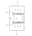
- FIG. 9 is a view showing a state before shrinking of the packaging sheet 20 used in the container set 10.
- the band portion 36 as described above may be provided at the upper end of the cylindrical portion 22 as shown in FIG.
- the band portion 36 is partially connected to each cylindrical portion 22, while being partially separated by a cut portion 38 formed at the end of the cylindrical portion 22.
- the band portion 36 is not provided with the boundary joint portion 30, and is a single large ring that surrounds all of the plurality of containers 12.
- the band portion 36 is shrunk in a state of surrounding all of the plurality of containers 12, so that the movement of the plurality of containers 12 is restricted by the band portion 36 as shown in FIG. Can be kept in.
- FIG. 9 is a front view of the packaging sheet 20 provided with the band portion 36 before shrinking.
- the packaging sheet 20 Prior to shrinking, the packaging sheet 20 includes three cylindrical portions 22 divided by the boundary joining portion 30 and a band portion 36 located above the cylindrical portion 22. A cut 38 is made only partially at the boundary between the cylindrical portion 22 and the band portion 36, and both are only partially connected.
- the container set 10 as illustrated in FIG. 7 can be obtained by heating the container 12 in a state where the container 12 is positioned inside each cylindrical portion 22 of the packaging sheet 20.
- the band portion 36 is expected to become an obstacle when the containers 12 are taken out and used individually. Therefore, in order to be able to easily remove the band portion 36 in use, the connection portion between the band portion 36 and the cylindrical portion 22 (the cut portion 38 is not provided in the boundary portion between the band portion 36 and the cylindrical portion 22). It is desirable to give a semi-breaking line such as a perforation line to (part).
- FIG. 10 is a schematic front view of the container set 10 shown as a reference.
- the connecting portion 24 between the respective cylindrical portions 22 is only at one place.
- each container 12 becomes relatively easy to move about the connecting part 24 as an axis, and there is a problem that the mutual positional relationship cannot be fixed.
- FIG. 10 shows that when a plurality of containers 12 each having only one wide portion 16 having the maximum width are connected by the respective cylindrical portions 22, the connecting portion 24 between the respective cylindrical portions 22 is only at one place. Become.
- each container 12 becomes relatively easy to move about the connecting part 24 as an axis, and there is a problem that the mutual positional relationship cannot be fixed.
- FIG. 10 is a schematic front view of the container set 10 shown as a reference.
- the band part 36 When the band part 36 has only one connection part 24, the band part 36 is provided close to the connection part 24, so that the connection part 24 easily receives the contraction force at the time of thermal contraction of the band part 36. It becomes easy to secure the positional relationship between the containers 12 later.
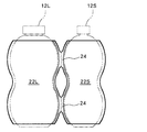
- the containers 12 having different shapes are connected. May be.
- a thick gourd-shaped container 12L and a narrow gourd-shaped container 12S may be connected by a packaging sheet 20 having a plurality of cylindrical portions 22L, 22S.
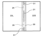
- the sizes of the two cylindrical portions 22L and 22S are made different at the stage before shrinking. That is, as shown in FIG. 11B, the position of the boundary joint 30 may be adjusted so that the large diameter cylindrical portion 22L and the small diameter cylindrical portion 22S are aligned.
- a plurality of containers 12 constituting the container set 10 has a shape in which the plurality of wide portions 16 are arranged apart from each other in the height direction. Therefore, as shown in FIG. 12, a plurality of containers may include a shell-shaped container 12N having a substantially constant cross-sectional shape.
- the cylindrical portion 22 that covers each container 12 is connected to the adjacent cylindrical portion 22 at least in the wide-width portion 16 and is separated from the adjacent cylindrical portion 22 in at least the narrow-width portion 18.
- a plurality of containers 12 can be reliably connected only by the packaging sheet 20 while maintaining a good aesthetic appearance.
Landscapes
- Engineering & Computer Science (AREA)
- Mechanical Engineering (AREA)
- Ceramic Engineering (AREA)
- Packages (AREA)
- Containers Having Bodies Formed In One Piece (AREA)
Abstract
Description
12 容器
14 蓋体
16 広幅部
18 狭幅部
20 包装シート
22 筒部
24 繋がり部
26 半破断線
28 貫通孔
30 境界接合部
31 切り込み線
32 連結接合部
36 バンド部
38 切り込み部
Claims (4)
- 複数の容器を、包装シートで連結包装した容器セットであって、
少なくとも一つの容器は、連結方向の幅が他部位に比して広い複数の広幅部が、当該広幅部より狭幅の狭幅部を挟んで両側に形成された形状を有し、
包装シートは、各容器の外形に沿って収縮し当該容器を個別に収容した筒部を複数個有しており、
これらの各筒部は、上記広幅部に対応する筒部の少なくとも一部に互いに隣接する筒部間において繋がり部を形成し、上記狭幅部の互いに対向する筒部間は繋がり部を形成せず分離した、ことを特徴とする容器セット。 - 請求項1に記載の容器セットであって、
隣接する筒部間の繋がり部には、当該繋がり部の切断を助ける半破断線が形成されている、ことを特徴とする容器セット。 - 請求項1または2に記載の容器セットであって、さらに、
複数の容器全てを取り囲んだ状態でシュリンクされることで当該複数の容器の動きを拘束するバンド部であって、各筒部に部分的に繋がり、部分的に分離したバンド部、を備えたことを特徴とする容器セット。 - 請求項3に記載の容器セットであって、
前記バンド部は、筒部の上側および下側の少なくとも一方に設けられている、ことを特徴とする容器セット。
Priority Applications (5)
| Application Number | Priority Date | Filing Date | Title |
|---|---|---|---|
| MX2012001925A MX2012001925A (es) | 2009-08-17 | 2010-07-16 | Conjunto de recipientes. |
| EP10809800.5A EP2468660B1 (en) | 2009-08-17 | 2010-07-16 | Container set |
| BR112012003591A BR112012003591A2 (pt) | 2009-08-17 | 2010-07-16 | conjunto de recipientes |
| ES10809800T ES2431074T3 (es) | 2009-08-17 | 2010-07-16 | Conjunto de recipientes |
| US13/389,714 US8701885B2 (en) | 2009-08-17 | 2010-07-16 | Container set |
Applications Claiming Priority (2)
| Application Number | Priority Date | Filing Date | Title |
|---|---|---|---|
| JP2009-188770 | 2009-08-17 | ||
| JP2009188770A JP5363911B2 (ja) | 2009-08-17 | 2009-08-17 | 容器セット |
Publications (1)
| Publication Number | Publication Date |
|---|---|
| WO2011021455A1 true WO2011021455A1 (ja) | 2011-02-24 |
Family
ID=43606910
Family Applications (1)
| Application Number | Title | Priority Date | Filing Date |
|---|---|---|---|
| PCT/JP2010/062046 Ceased WO2011021455A1 (ja) | 2009-08-17 | 2010-07-16 | 容器セット |
Country Status (7)
| Country | Link |
|---|---|
| US (1) | US8701885B2 (ja) |
| EP (1) | EP2468660B1 (ja) |
| JP (1) | JP5363911B2 (ja) |
| BR (1) | BR112012003591A2 (ja) |
| ES (1) | ES2431074T3 (ja) |
| MX (1) | MX2012001925A (ja) |
| WO (1) | WO2011021455A1 (ja) |
Cited By (1)
| Publication number | Priority date | Publication date | Assignee | Title |
|---|---|---|---|---|
| JP2011189988A (ja) * | 2010-02-20 | 2011-09-29 | Fuji Seal International Inc | 複数物品包装体及び複数物品包装用ラベル |
Families Citing this family (10)
| Publication number | Priority date | Publication date | Assignee | Title |
|---|---|---|---|---|
| JP2012192931A (ja) * | 2011-03-15 | 2012-10-11 | Fuji Seal International Inc | フィルム包装体及びその製造方法 |
| JP5732635B2 (ja) * | 2011-03-15 | 2015-06-10 | 株式会社フジシール | フィルム包材及びそれを用いた包装体 |
| US20140059810A1 (en) * | 2012-08-31 | 2014-03-06 | AKACAS IP Holdings, LLC | Bottle bracelet |
| JP2016540703A (ja) * | 2013-11-14 | 2016-12-28 | ラクトート プロプライエタリー リミテッド | 改良型収縮ラップ包装 |
| EP2883681B1 (en) * | 2013-12-16 | 2018-09-12 | Discma AG | Plurality of containers and package comprising a plurality of containers |
| JP6707374B2 (ja) * | 2016-03-17 | 2020-06-10 | 株式会社フジシールインターナショナル | 包装構造 |
| US20190144181A1 (en) * | 2016-04-08 | 2019-05-16 | Serena Fiorella | Product presentation assembly |
| CA3120345A1 (en) | 2018-12-07 | 2020-06-11 | Bedford Industries, Inc. | Tag attachment by shrink film |
| FR3112129B1 (fr) * | 2020-07-03 | 2023-04-14 | Sidel Participations | Dispositif de conditionnement pour former un pack |
| JP1809647S (ja) * | 2024-03-25 | 2025-10-01 | ひょうたんボトル |
Citations (1)
| Publication number | Priority date | Publication date | Assignee | Title |
|---|---|---|---|---|
| JPH11147564A (ja) * | 1997-11-13 | 1999-06-02 | Okura Ind Co Ltd | 熱収縮性フィルム、及び該フィルムの製造方法 |
Family Cites Families (16)
| Publication number | Priority date | Publication date | Assignee | Title |
|---|---|---|---|---|
| US2008659A (en) * | 1931-12-10 | 1935-07-16 | Leroy L Salfisberg | Package and method of making same |
| FR1135850A (fr) * | 1954-08-18 | 1957-05-03 | Philips Nv | Emballage pour lampes-éclair |
| US3812962A (en) * | 1972-03-31 | 1974-05-28 | Grip Pak Inc | Container package |
| JPS5264680U (ja) * | 1975-11-04 | 1977-05-13 | ||
| US4099616A (en) * | 1977-04-14 | 1978-07-11 | Illinois Tool Works Inc. | Two-bottle package and bag |
| US4377234A (en) | 1981-03-16 | 1983-03-22 | Halpak Plastics Inc. | Multiple compartment banding sleeve |
| FR2637866B1 (fr) | 1988-10-19 | 1991-03-29 | Sleever Int | Procede d'emballage d'objets sous gaine plastique thermoretractable a plusieurs compartiments |
| GB8909431D0 (en) | 1989-04-25 | 1989-06-14 | Harlands Of Hull Ltd | A method of packaging objects |
| US5651453A (en) | 1995-09-01 | 1997-07-29 | Illinois Tool Works Inc. | Carrier hole configuration to prevent zipper from prematurely disengaging |
| FR2733733B1 (fr) * | 1995-05-05 | 1997-06-13 | Serre Robert | Procede et dispositif d'impression et de fabrication de manchons ou fourreaux d'emballage et produits correspondants |
| IT1277060B1 (it) * | 1995-12-12 | 1997-11-04 | Cielle Di Loreto Tommaso | Metodo per formare una confezione di una pluralita' di contenitori che sia facilmente rompibile |
| JP3025920U (ja) * | 1995-12-15 | 1996-06-25 | 株式会社テクノパック | 複数物品結束包装材 |
| US7021479B2 (en) * | 2004-06-04 | 2006-04-04 | Plastipak Packaging, Inc. | Plastic container with sidewall vacuum panels |
| US7686178B2 (en) * | 2005-10-28 | 2010-03-30 | The Coca-Cola Company | Flask |
| US7832553B2 (en) * | 2006-03-17 | 2010-11-16 | Illinois Tool Works Inc. | Heat-shrinkable holder for articles, heat-shrinkable package of articles, heat-shrinkable sleeve for articles, and method and device for packaging and sleeving articles |
| CN201472905U (zh) * | 2009-04-17 | 2010-05-19 | 沈向东 | 一种葫芦酒瓶 |
-
2009
- 2009-08-17 JP JP2009188770A patent/JP5363911B2/ja not_active Expired - Fee Related
-
2010
- 2010-07-16 ES ES10809800T patent/ES2431074T3/es active Active
- 2010-07-16 WO PCT/JP2010/062046 patent/WO2011021455A1/ja not_active Ceased
- 2010-07-16 EP EP10809800.5A patent/EP2468660B1/en not_active Not-in-force
- 2010-07-16 BR BR112012003591A patent/BR112012003591A2/pt not_active IP Right Cessation
- 2010-07-16 MX MX2012001925A patent/MX2012001925A/es active IP Right Grant
- 2010-07-16 US US13/389,714 patent/US8701885B2/en not_active Expired - Fee Related
Patent Citations (1)
| Publication number | Priority date | Publication date | Assignee | Title |
|---|---|---|---|---|
| JPH11147564A (ja) * | 1997-11-13 | 1999-06-02 | Okura Ind Co Ltd | 熱収縮性フィルム、及び該フィルムの製造方法 |
Non-Patent Citations (1)
| Title |
|---|
| See also references of EP2468660A4 * |
Cited By (1)
| Publication number | Priority date | Publication date | Assignee | Title |
|---|---|---|---|---|
| JP2011189988A (ja) * | 2010-02-20 | 2011-09-29 | Fuji Seal International Inc | 複数物品包装体及び複数物品包装用ラベル |
Also Published As
| Publication number | Publication date |
|---|---|
| US20120138498A1 (en) | 2012-06-07 |
| JP2011037502A (ja) | 2011-02-24 |
| ES2431074T3 (es) | 2013-11-25 |
| MX2012001925A (es) | 2012-03-21 |
| EP2468660A4 (en) | 2013-01-23 |
| US8701885B2 (en) | 2014-04-22 |
| EP2468660B1 (en) | 2013-09-18 |
| JP5363911B2 (ja) | 2013-12-11 |
| BR112012003591A2 (pt) | 2016-03-15 |
| EP2468660A1 (en) | 2012-06-27 |
Similar Documents
| Publication | Publication Date | Title |
|---|---|---|
| JP5363911B2 (ja) | 容器セット | |
| EP3439866B1 (en) | Thermally laminated tab liner | |
| JP2010222050A (ja) | 包装スリーブ及びこれを含む複合包装材 | |
| US11787153B2 (en) | Thermally laminated tab liner | |
| WO2012017938A1 (ja) | 容器及びその製造方法 | |
| JP2008308214A (ja) | 手提げ孔付き米袋 | |
| US20240337122A1 (en) | Inflatable pool | |
| JP6593027B2 (ja) | 複合容器 | |
| JP6639879B2 (ja) | キャップシール付き容器、及びキャップシール | |
| JP6308776B2 (ja) | 熱収縮性巻付けラベル | |
| JP6406609B2 (ja) | 包装袋 | |
| JP6290634B2 (ja) | 包装袋 | |
| JP2010279640A (ja) | 簡易担架及びその製造方法 | |
| JP2015229495A (ja) | 包材およびこの包材を用いた包装体の製造方法 | |
| JP2005022741A (ja) | スタンディングパウチ | |
| JP6579761B2 (ja) | 包材および包装体 | |
| JP6878879B2 (ja) | 包装袋 | |
| JP6752561B2 (ja) | 支持体付包装体に用いられる支持体および支持体付フィルム包装体 | |
| JP6538900B2 (ja) | 包装袋 | |
| JP2019137420A (ja) | ラベル付き容器及び熱収縮性筒状ラベル | |
| JP2015006906A (ja) | ガゼット袋 | |
| JP6585448B2 (ja) | 包装体 | |
| JP5476628B2 (ja) | フィルム包装体 | |
| JP7339081B2 (ja) | 包材 | |
| JP6261293B2 (ja) | 包材およびこの包材を用いた包装体の製造方法 |
Legal Events
| Date | Code | Title | Description |
|---|---|---|---|
| 121 | Ep: the epo has been informed by wipo that ep was designated in this application |
Ref document number: 10809800 Country of ref document: EP Kind code of ref document: A1 |
|
| WWE | Wipo information: entry into national phase |
Ref document number: 13389714 Country of ref document: US |
|
| WWE | Wipo information: entry into national phase |
Ref document number: MX/A/2012/001925 Country of ref document: MX |
|
| NENP | Non-entry into the national phase |
Ref country code: DE |
|
| WWE | Wipo information: entry into national phase |
Ref document number: 2010809800 Country of ref document: EP |
|
| REG | Reference to national code |
Ref country code: BR Ref legal event code: B01A Ref document number: 112012003591 Country of ref document: BR |
|
| ENP | Entry into the national phase |
Ref document number: 112012003591 Country of ref document: BR Kind code of ref document: A2 Effective date: 20120216 |