WO2011024447A1 - ランフラットタイヤ - Google Patents
ランフラットタイヤ Download PDFInfo
- Publication number
- WO2011024447A1 WO2011024447A1 PCT/JP2010/005229 JP2010005229W WO2011024447A1 WO 2011024447 A1 WO2011024447 A1 WO 2011024447A1 JP 2010005229 W JP2010005229 W JP 2010005229W WO 2011024447 A1 WO2011024447 A1 WO 2011024447A1
- Authority
- WO
- WIPO (PCT)
- Prior art keywords
- tire
- run
- carcass
- bead
- width direction
- Prior art date
- Legal status (The legal status is an assumption and is not a legal conclusion. Google has not performed a legal analysis and makes no representation as to the accuracy of the status listed.)
- Ceased
Links
Images


Classifications
-
- B—PERFORMING OPERATIONS; TRANSPORTING
- B60—VEHICLES IN GENERAL
- B60C—VEHICLE TYRES; TYRE INFLATION; TYRE CHANGING; CONNECTING VALVES TO INFLATABLE ELASTIC BODIES IN GENERAL; DEVICES OR ARRANGEMENTS RELATED TO TYRES
- B60C17/00—Tyres characterised by means enabling restricted operation in damaged or deflated condition; Accessories therefor
- B60C17/0009—Tyres characterised by means enabling restricted operation in damaged or deflated condition; Accessories therefor comprising sidewall rubber inserts, e.g. crescent shaped inserts
-
- B—PERFORMING OPERATIONS; TRANSPORTING
- B60—VEHICLES IN GENERAL
- B60C—VEHICLE TYRES; TYRE INFLATION; TYRE CHANGING; CONNECTING VALVES TO INFLATABLE ELASTIC BODIES IN GENERAL; DEVICES OR ARRANGEMENTS RELATED TO TYRES
- B60C13/00—Tyre sidewalls; Protecting, decorating, marking, or the like, thereof
-
- B—PERFORMING OPERATIONS; TRANSPORTING
- B60—VEHICLES IN GENERAL
- B60C—VEHICLE TYRES; TYRE INFLATION; TYRE CHANGING; CONNECTING VALVES TO INFLATABLE ELASTIC BODIES IN GENERAL; DEVICES OR ARRANGEMENTS RELATED TO TYRES
- B60C15/00—Tyre beads, e.g. ply turn-up or overlap
- B60C15/0009—Tyre beads, e.g. ply turn-up or overlap features of the carcass terminal portion
-
- B—PERFORMING OPERATIONS; TRANSPORTING
- B60—VEHICLES IN GENERAL
- B60C—VEHICLE TYRES; TYRE INFLATION; TYRE CHANGING; CONNECTING VALVES TO INFLATABLE ELASTIC BODIES IN GENERAL; DEVICES OR ARRANGEMENTS RELATED TO TYRES
- B60C15/00—Tyre beads, e.g. ply turn-up or overlap
- B60C15/0009—Tyre beads, e.g. ply turn-up or overlap features of the carcass terminal portion
- B60C15/0018—Tyre beads, e.g. ply turn-up or overlap features of the carcass terminal portion not folded around the bead core, e.g. floating or down ply
-
- B—PERFORMING OPERATIONS; TRANSPORTING
- B60—VEHICLES IN GENERAL
- B60C—VEHICLE TYRES; TYRE INFLATION; TYRE CHANGING; CONNECTING VALVES TO INFLATABLE ELASTIC BODIES IN GENERAL; DEVICES OR ARRANGEMENTS RELATED TO TYRES
- B60C9/00—Reinforcements or ply arrangement of pneumatic tyres
- B60C9/02—Carcasses
- B60C9/0207—Carcasses comprising an interrupted ply, i.e. where the carcass ply does not continuously extend from bead to bead but is interrupted, e.g. at the belt area, into two or more portions of the same ply
-
- B—PERFORMING OPERATIONS; TRANSPORTING
- B60—VEHICLES IN GENERAL
- B60C—VEHICLE TYRES; TYRE INFLATION; TYRE CHANGING; CONNECTING VALVES TO INFLATABLE ELASTIC BODIES IN GENERAL; DEVICES OR ARRANGEMENTS RELATED TO TYRES
- B60C9/00—Reinforcements or ply arrangement of pneumatic tyres
- B60C9/02—Carcasses
- B60C9/04—Carcasses the reinforcing cords of each carcass ply arranged in a substantially parallel relationship
-
- B—PERFORMING OPERATIONS; TRANSPORTING
- B60—VEHICLES IN GENERAL
- B60C—VEHICLE TYRES; TYRE INFLATION; TYRE CHANGING; CONNECTING VALVES TO INFLATABLE ELASTIC BODIES IN GENERAL; DEVICES OR ARRANGEMENTS RELATED TO TYRES
- B60C9/00—Reinforcements or ply arrangement of pneumatic tyres
- B60C9/02—Carcasses
- B60C9/04—Carcasses the reinforcing cords of each carcass ply arranged in a substantially parallel relationship
- B60C9/08—Carcasses the reinforcing cords of each carcass ply arranged in a substantially parallel relationship the cords extend transversely from bead to bead, i.e. radial ply
- B60C9/09—Carcasses the reinforcing cords of each carcass ply arranged in a substantially parallel relationship the cords extend transversely from bead to bead, i.e. radial ply combined with other carcass plies having cords extending diagonally from bead to bead, i.e. combined radial ply and bias angle ply
-
- B—PERFORMING OPERATIONS; TRANSPORTING
- B60—VEHICLES IN GENERAL
- B60C—VEHICLE TYRES; TYRE INFLATION; TYRE CHANGING; CONNECTING VALVES TO INFLATABLE ELASTIC BODIES IN GENERAL; DEVICES OR ARRANGEMENTS RELATED TO TYRES
- B60C9/00—Reinforcements or ply arrangement of pneumatic tyres
- B60C9/02—Carcasses
- B60C9/04—Carcasses the reinforcing cords of each carcass ply arranged in a substantially parallel relationship
- B60C2009/0416—Physical properties or dimensions of the carcass cords
-
- B—PERFORMING OPERATIONS; TRANSPORTING
- B60—VEHICLES IN GENERAL
- B60C—VEHICLE TYRES; TYRE INFLATION; TYRE CHANGING; CONNECTING VALVES TO INFLATABLE ELASTIC BODIES IN GENERAL; DEVICES OR ARRANGEMENTS RELATED TO TYRES
- B60C9/00—Reinforcements or ply arrangement of pneumatic tyres
- B60C9/02—Carcasses
- B60C9/04—Carcasses the reinforcing cords of each carcass ply arranged in a substantially parallel relationship
- B60C2009/0416—Physical properties or dimensions of the carcass cords
- B60C2009/0433—Modulus
-
- B—PERFORMING OPERATIONS; TRANSPORTING
- B60—VEHICLES IN GENERAL
- B60C—VEHICLE TYRES; TYRE INFLATION; TYRE CHANGING; CONNECTING VALVES TO INFLATABLE ELASTIC BODIES IN GENERAL; DEVICES OR ARRANGEMENTS RELATED TO TYRES
- B60C9/00—Reinforcements or ply arrangement of pneumatic tyres
- B60C9/02—Carcasses
- B60C9/04—Carcasses the reinforcing cords of each carcass ply arranged in a substantially parallel relationship
- B60C2009/0475—Particular materials of the carcass cords
-
- B—PERFORMING OPERATIONS; TRANSPORTING
- B60—VEHICLES IN GENERAL
- B60C—VEHICLE TYRES; TYRE INFLATION; TYRE CHANGING; CONNECTING VALVES TO INFLATABLE ELASTIC BODIES IN GENERAL; DEVICES OR ARRANGEMENTS RELATED TO TYRES
- B60C15/00—Tyre beads, e.g. ply turn-up or overlap
- B60C15/0009—Tyre beads, e.g. ply turn-up or overlap features of the carcass terminal portion
- B60C2015/009—Height of the carcass terminal portion defined in terms of a numerical value or ratio in proportion to section height
-
- Y—GENERAL TAGGING OF NEW TECHNOLOGICAL DEVELOPMENTS; GENERAL TAGGING OF CROSS-SECTIONAL TECHNOLOGIES SPANNING OVER SEVERAL SECTIONS OF THE IPC; TECHNICAL SUBJECTS COVERED BY FORMER USPC CROSS-REFERENCE ART COLLECTIONS [XRACs] AND DIGESTS
- Y10—TECHNICAL SUBJECTS COVERED BY FORMER USPC
- Y10T—TECHNICAL SUBJECTS COVERED BY FORMER US CLASSIFICATION
- Y10T152/00—Resilient tires and wheels
- Y10T152/10—Tires, resilient
- Y10T152/10495—Pneumatic tire or inner tube
- Y10T152/10855—Characterized by the carcass, carcass material, or physical arrangement of the carcass materials
- Y10T152/10864—Sidewall stiffening or reinforcing means other than main carcass plies or foldups thereof about beads
-
- Y—GENERAL TAGGING OF NEW TECHNOLOGICAL DEVELOPMENTS; GENERAL TAGGING OF CROSS-SECTIONAL TECHNOLOGIES SPANNING OVER SEVERAL SECTIONS OF THE IPC; TECHNICAL SUBJECTS COVERED BY FORMER USPC CROSS-REFERENCE ART COLLECTIONS [XRACs] AND DIGESTS
- Y10—TECHNICAL SUBJECTS COVERED BY FORMER USPC
- Y10T—TECHNICAL SUBJECTS COVERED BY FORMER US CLASSIFICATION
- Y10T152/00—Resilient tires and wheels
- Y10T152/10—Tires, resilient
- Y10T152/10495—Pneumatic tire or inner tube
- Y10T152/10855—Characterized by the carcass, carcass material, or physical arrangement of the carcass materials
- Y10T152/10873—Characterized by the carcass, carcass material, or physical arrangement of the carcass materials with two or more differing cord materials
Definitions
- the present invention relates to a so-called sidewall-reinforced run-flat tire in which a reinforcing rubber is disposed on a sidewall portion to enhance rigidity, and in particular, the ride comfort is improved by suppressing vibration during traveling.
- the present invention relates to a run-flat tire having improved run-flat durability (durability after puncture, hereinafter may be abbreviated as RF durability).
- a run-flat tire that can safely run for a fixed distance even in a punctured state (when the internal pressure is zero) is provided with a reinforcing rubber on the side wall as in the tires described in Patent Documents 1 to 4, for example. Reinforced, so-called sidewall reinforced type is generally used.
- the run-flat tire has a side reinforcing rubber made of a rubber composition having rigidity higher than that of the surrounding rubber component in the sidewall portion, and has a higher elastic modulus in the load direction than a normal tire.
- radial force variation increases, uniformity may be impaired, and vibration may occur during travel.
- the radial force variation refers to the magnitude of force fluctuation in the tire radial direction (z-axis direction) that occurs while the tire receiving a load makes one revolution at a constant radius.
- RFV the radial force variation
- the inventors of the present invention have been diligently studying how to solve the above-mentioned problems, and the rayon material used for the carcass ply of many run-flat tires is compared with the PET material used for the carcass ply of normal tires. It was found that the heat shrinkage rate was as low as 1/3, which caused variations in the length of the ply cord on the circumference of the product after vulcanization, which caused the deterioration of RFV.
- the carcass ply of the run flat tire has a high temperature around 200 ° C. around the side reinforcing rubber when running at zero internal pressure
- the above-mentioned PET material having poor heat resistance is used for the carcass ply of the run flat tire.
- a sufficient traveling distance cannot be obtained, and a break may occur in a short period of time. Therefore, conventionally, it has been difficult to apply a PET material to a run-flat tire from the viewpoint of maintaining RF durability.
- a particularly strong material to the carcass material of the run flat tire in terms of tire strength. That is, when running on a road surface that has a certain distance or more, such as a pothole or dent, the tire may suddenly receive an excessive vertical force.
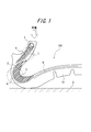
- FIG. 1 is a half-sectional view in the width direction showing a state of contact with a road surface when a normal sidewall-reinforced run-flat tire 100 travels at zero internal pressure.
- the run-flat tire 100 in the illustrated example has a single carcass 2 straddling a toroidal shape between a pair of bead portions 7, and a belt 9 and a tread portion 10 are sequentially arranged on the radially outer side of the crown portion of the carcass 2.
- a sidewall portion 8 is provided between the tread portion 10 and both bead portions 7, a bead core 5 and a bead filler 4 are disposed on both bead portions 7, and side reinforcement is provided on the inside of the carcass 2 of both sidewall portions 8.
- the run flat tire 100 is provided with a rubber 3. In the illustrated example, the run-flat tire 100 is in contact with the road surface G with zero internal pressure, and is bent by receiving a load in the road surface direction.
- the side reinforcing rubber 3 and the bead filler 4 are bent to increase the path length of the carcass 2.
- a strong tensile stress is applied in the vicinity (portion surrounded by a broken-line circle in the illustrated example).
- the carcass 2 in the vicinity of the sidewall 8 tends to be subjected to a larger tensile stress by being sandwiched between the road surface and the reinforcing rubber 3, so that the tensile strength of the cord used for the carcass ply becomes a problem particularly in this portion. Therefore, a PET material having a strength per unit dtex of 1.5 to 1.7 times that of rayon is effective for this problem if the carcass ply is not exposed to a high temperature near 200 ° C. .
- an object of the present invention is to provide a run-flat tire that improves riding comfort by suppressing vibration during traveling and that is also excellent in run-flat durability.
- the present inventors have as follows. I came to know. In other words, the problem is that the carcass ply of the run-flat tire requires both a shape retention function when filling with internal pressure and a load-supporting function at high temperatures during run-flat running. It has been found that the above problems can be solved by separating functions and assigning materials for each desired function. Therefore, the gist configuration of the present invention for solving the above-described problems is as follows.
- a carcass composed of at least one carcass ply straddling a toroidal shape between bead cores embedded in a pair of bead portions is used as a skeleton, and a belt and a tread portion are sequentially arranged on the radially outer side of the crown portion of the carcass
- the carcass ply includes a cord made of a material having a heat shrinkage rate of 2 to 8% at 177 ° C., and the run-flat tire is on the outer side in the tire width direction of the side reinforcing rubber on both sidewall portions
- a run flat tire comprising a reinforcing cord layer including a cord made of a material having a heat shrinkage rate of less than 2% at 177 ° C.
- polyester fiber examples include polyethylene terephthalate (PET) and polyethylene naphthalate (PEN).
- PET polyethylene terephthalate
- PEN polyethylene naphthalate
- examples of the cellulose fiber include rayon and lyocell.
- the belt side end portion of the reinforcing cord layer is located on the inner side in the tire width direction than the width direction end of the belt, and the bead side end portion of the reinforcing cord layer is a bead core.
- the run-flat tire according to any one of (1) to (4), wherein the run-flat tire has a structure extending from the inner side to the outer side in the width direction.
- the belt-side end portion of the reinforcing cord layer refers to an end portion close to the outermost radial direction of the reinforcing cord layer in the tire width direction cross section
- the bead-side end portion of the reinforcing cord layer is In the cross section in the tire width direction, it refers to the end opposite to the end on the belt side.
- the end in the width direction of the belt means the outermost end in the width direction of the belt layer having the maximum width when the belt is composed of a plurality of belt layers.
- the inclusion of the bead filler means that at least one of the carcass and the reinforcing cord layer extends by being rewound from the inner side to the outer side in the width direction of the tire at the bead core, and the tire at the tip of the rewound portion It means that the height in the radial direction is higher than the height in the tire radial direction of the bead filler.
- the carcass has a structure in which a bead core extends and extends from the inner side to the outer side in the width direction of the tire, and the height in the tire radial direction at the tip of the carcass is 25 mm or less.
- the run flat tire according to any one of (6).
- the tire radial height refers to the distance in the tire radial direction from the bead baseline.
- the bead base line is a straight line that extends in parallel with the tire rotation axis through the bead toe of the tire.
- the height in the tire radial direction at the tip of the wound carcass may be hereinafter referred to as a carcass folding height CH.
- the height in the tire radial direction at the tip of the wound reinforcing cord layer is hereinafter referred to as a folded height RH of the reinforcing cord layer.
- the run-flat tire of the present invention uses a material having a large heat shrinkage rate for the carcass ply, so that the length of the ply cord of the product after vulcanization becomes uniform and the RFV is good. As a result, it is possible to reduce vibration during traveling, which was a conventional problem.
- the run flat tire of the present invention has run flat durability by using a material having a low heat shrinkage rate, that is, a material having excellent heat resistance, on the outer side in the tire width direction of the side reinforcing rubber of both side wall portions. It is possible to improve.
- FIG. 6 is a half-sectional view in the width direction of a conventional run flat tire that travels with zero internal pressure.
- 1 is a half-sectional view in the width direction of a run flat tire according to the present invention.
- 1 is a half-sectional view in the width direction of a run flat tire according to the present invention.
- 1 is a half-sectional view in the width direction of a run flat tire according to the present invention.
- 1 is a half-sectional view in the width direction of a run flat tire according to the present invention.
- 1 is a half-sectional view in the width direction of a run flat tire according to the present invention.
- It is a mimetic diagram of a pendulum type cut testing machine used for evaluation of side cut resistance.
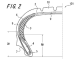
- the run flat tire 101 shown in FIG. 2 has a carcass 2 composed of at least one toroidal shape between the bead cores 5 embedded in the pair of bead portions 7, in the illustrated example, one carcass ply.
- a belt 9 and a tread portion 10 are arranged in order on the radially outer side of the crown portion, and a sidewall portion 8 is provided between the tread portion 10 and both bead portions 7, and the tire width direction of the carcass 2 in both sidewall portions.
- Side reinforcing rubber 3 is disposed on the inner side. In the illustrated example, the side reinforcing rubber 3 has a substantially crescent-shaped cross section.
- the run-flat tire 101 in the illustrated example includes a bead filler 4 on the outer side in the tire radial direction of the bead core 5.
- the carcass ply includes a cord made of a material having a heat shrinkage rate of 2 to 8% at 177 ° C.
- the run-flat tire 101 includes the side reinforcements of both sidewall portions 8. It is important that the reinforcing cord layer 6 including a cord made of a material having a thermal shrinkage rate of less than 2% at 177 ° C. is provided outside the rubber 3 in the tire width direction.
- the belt side end portion of the reinforcing cord layer 6 is located on the inner side in the tire width direction with respect to the width direction end of the belt 9.
- the bead side end portion is a structure that extends by being rolled back from the inner side in the width direction of the tire by the bead core 5.
- the said carcass 2 is a structure wound up and extended from the inner side of the width direction of a tire to the outer side by the bead core 5, Preferably it is a radial carcass.
- the heat shrinkage rate is a ratio obtained by putting a sample (length: 250 mm) in an oven at 177 ° C. for 120 seconds, measuring the amount of shrinkage in the length direction, and dividing the amount of shrinkage by the length of the entire sample. Say that.
- the length of the ply cord becomes uniform in the vulcanized tire, so that the RFV is improved. Thereby, it is possible to reduce tire vibration and improve riding comfort.
- the RF durability of the tire is improved by disposing a reinforcing cord layer 6 including a cord made of a material having a small heat shrinkage rate, that is, a material having high heat resistance, on the outer side in the tire width direction of the side reinforcing rubber 3.
- a reinforcing cord layer 6 including a cord made of a material having a small heat shrinkage rate, that is, a material having high heat resistance, on the outer side in the tire width direction of the side reinforcing rubber 3.
- the reinforcing cord layer 6 exhibits the necessary rigidity due to excellent heat resistance even in a high temperature region around the reinforcing rubber 3 (maximum temperature less than 200 ° C.). It is possible to obtain a run-flat mileage.
- the reinforcing cord layer 6 may be disposed outside the reinforcing rubber layer 3 in the tire width direction.
- the reinforcing cord layer 6 is inside the carcass 2 in the tire radial direction, that is, between the carcass 2 and the reinforcing rubber layer 3. It is also possible to arrange them.
- the carcass ply includes a cord made of polyester fiber.
- polyester fibers have higher strength than cellulosic fiber materials and the like, and therefore, the side cut resistance of a tire can be improved by applying the polyester fibers to a carcass ply cord.
- side-cut resistance means that the side wall portion 8 is violently plunged into irregularities (potholes or cat's eyes) on the road surface or suddenly receives up-and-down input on a wavy road. It refers to the durability of a tire against scratches and breaks (so-called side cuts) that occur.
- the reinforcing cord layer 6 includes a cord made of cellulosic fibers.
- cellulosic fibers have a smaller heat shrinkage than polyester fibers and are excellent in heat resistance. Therefore, it is possible to further improve the RF durability of the tire by disposing a cord made of cellulosic fibers in the reinforcing cord layer 6.
- the inclination angle of the cord of the reinforcing cord layer 6 with respect to the tire radial direction is preferably 0 to 20 °.
- the reinforcing cord layer 6 maintains the shape of the tire by restraining the bending deformation of the reinforcing rubber 3 from the outside during the run-flat running of the tire.
- the rigidity of the reinforcing cord layer 6 against the elongation in the tire circumferential direction can be improved, and thereby the RF durability of the tire can be improved. It is possible to improve.
- the belt side end portion of the reinforcing cord layer 6 is located on the inner side in the tire width direction than the width direction end of the belt 9,
- the bead side end portion of the reinforcing cord layer 6 preferably has a structure in which the bead core 5 is wound and extended from the inner side to the outer side in the width direction of the tire.
- the reinforcing cord layer 6 has a belt-side end disposed on the inner side in the tire width direction with respect to the width-direction end of the belt 9, and the bead-side end is rolled back by the bead core 5, thereby The layer 6 restrains the bending deformation of the side reinforcing rubber 3 more firmly. Thereby, it is possible to further improve the RF durability.
- the reinforcing cord layer 6 having the above structure can be preferably applied to various road surface conditions, various tire sizes, and vehicle weights in the market.
- the bead side end of the reinforcing cord layer 6 is stopped before the bead core 5 and wound.
- a structure that does not return is also possible. For example, when the vehicle weight is light, etc., the tire strength is sufficient even with the above-described structure. Therefore, it is possible to reduce the weight of the tire by reducing the weight of the reinforcing cord layer 6.
- a bead filler 4 is disposed on the outer side in the tire radial direction of the bead core 5, and at least one of the carcass 2 and the reinforcing cord layer 6 includes the bead filler 4. It is preferable to enclose.
- the bead filler 4 has high hardness, end separation may occur due to deformation of the tire. Therefore, the occurrence of end separation can be suppressed by covering and restraining the bead filler 4 with the carcass 2 or the reinforcing cord layer 6 and suppressing deformation of the bead portion 7.
- the carcass 2 has a structure in which the bead core 5 is wound and extended from the inner side to the outer side in the width direction of the tire, and the tire radial height CH at the tip of the carcass 2 is extended.
- it is preferable that it is 25 mm or less.
- the tire weight can be reduced by setting the turn-up height CH of the carcass 2 to 25 mm or less.
- the run flat tire 101 shown in FIG. 2 has a carcass 2 folding height CH of 60 mm, and the reinforcing cord layer 6 has a folding height RH 50 mm.
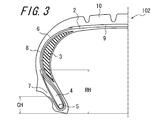
- the run flat tire 102 shown in FIG. The folded height CH is 20 mm, and the folded height RH of the reinforcing cord layer 6 is 50 mm.
- both the run flat tire 103 shown in FIG. 4 and the run flat tire 104 shown in FIG. 5 have a structure in which the folding height CH of the carcass 2 is 60 mm and the reinforcing cord layer 6 stops before the bead core 5.
- the width of the reinforcing cord layer 6 is different between them, the width of the reinforcing cord layer 6 of the run flat tire 103 is 90 mm, and the width of the reinforcing cord layer 6 of the run flat tire 104 is 60 mm. Furthermore, the run-flat tire 105 shown in FIG. 6 has a folded height CH of the carcass 2 of 60 mm and a folded height RH of the reinforcing cord layer 6 of 20 mm.
- the above-described run flat tires 101 to 105 according to the present invention have the same structure except that the structures of the carcass 2 and the reinforcing cord layer 6 are different as described above.
- the reinforcing cord layers 6 of the run-flat tires 101 to 105 of the embodiments introduced in this specification are all structured such that the belt side end portion is located on the inner side in the tire width direction than the width direction end of the belt 9 of the tire. That is, the reinforcing cord layer 6 and the belt 9 overlap each other at the end.
- the reinforcing cord layer 6 may be positioned outside the side reinforcing rubber 3. It is sufficient that the belt 9 does not necessarily overlap.
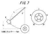
- FIG. 7 is a schematic diagram of a pendulum type cut test machine used for evaluation of side cut resistance in the following examples.
- Examples 1 to 5 five types of run flat tires having a tire size of 245/45 R19 were produced as Examples 1 to 5.
- the structure of the carcass 2 the material used for the ply and the folding height CH, the material of the reinforcing cord layer 6, the presence or absence of folding, the width and the folding height RH, and the height of the bead filler are: As shown in Table 1.
- Comparative Examples 1 and 2 Two types of run flat tires having no reinforcing cord layer 6 were produced in the same size as the above Examples 1 to 5, and were designated as Comparative Examples 1 and 2. At that time, carcass ply materials were distinguished from rayon and PET. Other specifications of Comparative Examples 1 and 2 are as shown in Table 1.
- the bead filler height refers to the distance in the tire radial direction from the outermost end in the tire radial direction of the bead filler to the outermost end in the tire radial direction of the bead core.
- Each test tire is mounted on a rim of size 7.5J and filled with an internal pressure of 230 MPa.
- the tester is made to collide with the test tire while changing the pendulum height h. By causing the collision, the pendulum height h until the side bulge at the ply break called bulge is generated, and the potential energy Mgh at that time is measured.
- a test tire was tested at five points I to V shown in FIG. 7, and the average value was calculated.
- Table 1 the side cut resistance of Comparative Example 1 is shown as an index with the value being 100, and the larger the value, the better the side cut resistance.
- Examples 1 to 5 having the structure of the run-flat tire according to the present invention are far superior to Comparative Example 1 in which rayon is used for the carcass ply in terms of RFV, and PET was used. It can be seen that the performance is almost equivalent to that of Comparative Example 2.
- Comparative Example 2 having a carcass ply made of a PET material and not having a reinforcing cord layer 6 tends to be remarkably inferior in terms of RF durability.
- Examples 1 to 5 having the cord layer 6 showed almost the same results as Comparative Example 1 having a carcass composed of two layers of a rayon material carcass ply excellent in heat resistance in terms of RF durability.
- Examples 1 to 5 are compared, Examples 1, 2, and 5 in which the reinforcing cord layer 6 is wound around the bead core 5 are examples 3 in which the reinforcing cord layer 6 is stopped before the bead core 5. More excellent in RF durability than 4 and 4.
- Examples 1 to 5 are superior to Comparative Example 1 in terms of side cut resistance. This is because the PET material used for the carcass plies of Examples 1 to 5 is superior in tensile strength to the rayon material used for the carcass ply of Comparative Example 1.
Landscapes
- Engineering & Computer Science (AREA)
- Mechanical Engineering (AREA)
- Tires In General (AREA)
Abstract
Description
前記カーカスプライは、177℃での熱収縮率が2~8%である材質からなるコードを含み、さらに、前記ランフラットタイヤは、両サイドウォール部の前記サイド補強ゴムのタイヤ幅方向外側に、177℃での熱収縮率が2%未満である材質からなるコードを含む補強コード層を、具えたことを特徴とするランフラットタイヤ。
図2~6は、本発明によるランフラットタイヤの一実施形態の幅方向断面図である。図2に示すランフラットタイヤ101は、一対のビード部7に埋設したビードコア5間にトロイダル状に跨る少なくとも1枚、図示例では1枚のカーカスプライからなるカーカス2を骨格とし、該カーカス2のクラウン部の径方向外側にベルト9およびトレッド部10を順に配置し、該トレッド部10と両ビード部7との間にサイドウォール部8を具え、両サイドウォール部の該カーカス2のタイヤ幅方向内側にサイド補強ゴム3を配設している。尚、図示例では、前記サイド補強ゴム3は、略三日月状の断面を有する。また、図示例のランフラットタイヤ101は、ビードコア5のタイヤ径方向外側にビードフィラー4を具えている。
各供試タイヤをサイズ7.5Jのリムに装着し、荷重5kN、内圧0.2MPaの条件下で、JIS D 4233に記載の方法に従って評価した。各実施例につき20本のランフラットタイヤについて評価した平均値を評価結果とした。尚、表1には、比較例1のRFVを100として指数表示してあり、数値が小さいほど、RFVが小さく、タイヤ性能に優れている。
各供試タイヤをサイズ7.5Jのリムに装着し、温度38℃の条件下で3時間予熱させた後、荷重6.57kN、温度38℃の条件下で、ドラム径1.6mのドラム試験機のドラムにバルブコアを抜いた状態で接地させた後、V=89km/hにて走行させ、破壊するまでの距離により評価した。ここで、上記破壊は、上記ドラム試験機に付設した振動センサにて判定した。尚、表1には、比較例1のRF耐久性を100として指数表示してあり、数値が大きいほど、RF耐久性に優れている。
リムに装着してない状態のタイヤの重量を測定した。表1には、比較例1のタイヤ重量を100として指数表示してあり、数値が小さいほど、軽量化の観点から好ましい。
各供試タイヤをサイズ7.5Jのリムに装着して、内圧を230MPa充填し、図7に示す、ストライカー形状R=50mm、振り子長さL=1829mm、振り子重量M=81.0kgの振り子型の試験機を用いて、振り子高さhを変化させながら供試タイヤに衝突させる。衝突させることによって、バルジと呼ばれるプライ破断でのサイドのふくれが発生するまでの、振り子高さhを割り出し、そのときの位置エネルギーMghを測定する。
一本の供試タイヤにつき、図7に示すI~Vの5箇所について試験を行い、その平均値を算出した。尚、表1には、比較例1の耐サイドカット性を100として指数表示してあり、数値が大きいほど、耐サイドカット性に優れている。

3:サイド補強ゴム
4:ビードフィラー
5:ビードコア
6:補強コード層
7:ビード部
8:サイドウォール部
9:ベルト
10:トレッド部
100:従来のランフラットタイヤ
101:本発明のランフラットタイヤ
102:本発明のランフラットタイヤ
103:本発明のランフラットタイヤ
104:本発明のランフラットタイヤ
105:本発明のランフラットタイヤ
G:路面
CH:カーカスの折り返し高さ
RH:補強コード層の折り返し高さ
Claims (7)
- 一対のビード部に埋設したビードコア間にトロイダル状に跨る少なくとも1枚のカーカスプライからなるカーカスを骨格とし、該カーカスのクラウン部の径方向外側にベルトおよびトレッド部を順に配置し、該トレッド部と両ビード部との間にサイドウォール部を具え、両サイドウォール部の該カーカスのタイヤ幅方向内側にサイド補強ゴムを配設したランフラットタイヤにおいて、
前記カーカスプライは、177℃での熱収縮率が2~8%である材質からなるコードを含み、さらに、前記ランフラットタイヤは、両サイドウォール部の前記サイド補強ゴムのタイヤ幅方向外側に、177℃での熱収縮率が2%未満である材質からなるコードを含む補強コード層を、具えたことを特徴とするランフラットタイヤ。 - 前記カーカスプライが、ポリエステル系繊維からなるコードを含む、請求項1に記載のランフラットタイヤ。
- 前記補強コード層が、セルロース系繊維からなるコードを含む、請求項1または2に記載のランフラットタイヤ。
- 前記補強コード層のコードのタイヤ径方向に対する傾斜角度が、0~20°である、請求項1~3のいずれかに記載のランフラットタイヤ。
- 前記補強コード層のベルト側端部が、前記ベルトの幅方向端よりもタイヤ幅方向内側に位置しており、さらに、前記補強コード層のビード側端部が、ビードコアにてタイヤの幅方向内側から外側へと巻き返されて延びる構造である、請求項1~4のいずれかに記載のランフラットタイヤ。
- 前記ビードコアのタイヤ径方向外側にビードフィラーが配設されており、前記カーカスおよび補強コード層の少なくとも一方が、該ビードフィラーを内包している、請求項1~5のいずれかに記載のランフラットタイヤ。
- 前記カーカスは、ビードコアにてタイヤの幅方向内側から外側へと巻き返されて延びる構造であり、該カーカスの先端のタイヤ径方向高さが、25mm以下である、請求項1~6のいずれかに記載のランフラットタイヤ。
Priority Applications (4)
| Application Number | Priority Date | Filing Date | Title |
|---|---|---|---|
| US13/392,180 US8925605B2 (en) | 2009-08-26 | 2010-08-25 | Run-flat tire |
| EP10811505.6A EP2471672B1 (en) | 2009-08-26 | 2010-08-25 | Run flat tyre |
| CN201080044054.8A CN102741069B (zh) | 2009-08-26 | 2010-08-25 | 缺气保用轮胎 |
| IN1426DEN2012 IN2012DN01426A (ja) | 2009-08-26 | 2012-02-15 |
Applications Claiming Priority (2)
| Application Number | Priority Date | Filing Date | Title |
|---|---|---|---|
| JP2009195935A JP5315171B2 (ja) | 2009-08-26 | 2009-08-26 | ランフラットタイヤ |
| JP2009-195935 | 2009-08-26 |
Publications (1)
| Publication Number | Publication Date |
|---|---|
| WO2011024447A1 true WO2011024447A1 (ja) | 2011-03-03 |
Family
ID=43627567
Family Applications (1)
| Application Number | Title | Priority Date | Filing Date |
|---|---|---|---|
| PCT/JP2010/005229 Ceased WO2011024447A1 (ja) | 2009-08-26 | 2010-08-25 | ランフラットタイヤ |
Country Status (6)
| Country | Link |
|---|---|
| US (1) | US8925605B2 (ja) |
| EP (1) | EP2471672B1 (ja) |
| JP (1) | JP5315171B2 (ja) |
| CN (1) | CN102741069B (ja) |
| IN (1) | IN2012DN01426A (ja) |
| WO (1) | WO2011024447A1 (ja) |
Cited By (1)
| Publication number | Priority date | Publication date | Assignee | Title |
|---|---|---|---|---|
| CN109109572A (zh) * | 2017-06-26 | 2019-01-01 | 住友橡胶工业株式会社 | 缺气保用轮胎以及用于制造缺气保用轮胎的方法 |
Families Citing this family (7)
| Publication number | Priority date | Publication date | Assignee | Title |
|---|---|---|---|---|
| JP5836054B2 (ja) * | 2011-10-25 | 2015-12-24 | 株式会社ブリヂストン | タイヤ試験方法 |
| JP5571206B1 (ja) * | 2013-02-05 | 2014-08-13 | 株式会社ブリヂストン | 電磁式発電機の装着方法及び電磁式発電機内蔵タイヤ |
| JP6317165B2 (ja) * | 2014-04-14 | 2018-04-25 | 株式会社ブリヂストン | ランフラットタイヤ |
| JP6408333B2 (ja) * | 2014-10-03 | 2018-10-17 | 株式会社ブリヂストン | ランフラットタイヤ |
| US10086658B2 (en) * | 2014-10-29 | 2018-10-02 | Bridgestone Corporation | Run-flat tire |
| JP6710995B2 (ja) * | 2016-02-08 | 2020-06-17 | 住友ゴム工業株式会社 | 空気入りタイヤ |
| JP7194584B2 (ja) * | 2018-12-21 | 2022-12-22 | Toyo Tire株式会社 | 空気入りタイヤ |
Citations (9)
| Publication number | Priority date | Publication date | Assignee | Title |
|---|---|---|---|---|
| JPH11291725A (ja) * | 1998-04-03 | 1999-10-26 | Bridgestone Corp | 空気入り安全タイヤ |
| JP2002500589A (ja) | 1997-05-29 | 2002-01-08 | ザ グッドイヤー タイヤ アンド ラバー カンパニー | 改良されたカーカスを有するランフラットタイヤ |
| JP2002500587A (ja) | 1997-05-29 | 2002-01-08 | ザ グッドイヤー タイヤ アンド ラバー カンパニー | 複合プライ構造を有するタイヤとその製造方法 |
| JP2004306658A (ja) | 2003-04-02 | 2004-11-04 | Bridgestone Corp | 空気入りタイヤ |
| JP2005014889A (ja) * | 2003-06-27 | 2005-01-20 | Goodyear Tire & Rubber Co:The | ポリエステルコード、およびランフラットタイヤにおけるその使用 |
| JP2006341771A (ja) * | 2005-06-09 | 2006-12-21 | Bridgestone Corp | 空気入り安全タイヤ |
| JP2009018771A (ja) * | 2007-07-13 | 2009-01-29 | Sumitomo Rubber Ind Ltd | ランフラットタイヤ |
| JP2009137449A (ja) * | 2007-12-06 | 2009-06-25 | Sumitomo Rubber Ind Ltd | ランフラットタイヤ |
| JP2009264012A (ja) | 2008-04-25 | 2009-11-12 | Tokai Rika Co Ltd | 施錠・解錠装置 |
Family Cites Families (9)
| Publication number | Priority date | Publication date | Assignee | Title |
|---|---|---|---|---|
| JPS5615321B2 (ja) * | 1973-09-20 | 1981-04-09 | ||
| US5795416A (en) * | 1996-08-02 | 1998-08-18 | Michelin Recherche Et Technique | Run-flat tire having partial carcass layers |
| US6619354B1 (en) * | 1998-12-17 | 2003-09-16 | Bridgestone Corporation | Run flat pneumatic tire with shoulder cushion rubber layer loss tangent less than carcass coating rubber loss tangent |
| US7448422B2 (en) * | 2004-04-22 | 2008-11-11 | The Goodyear Tire & Rubber Company | Pneumatic run-flat tire |
| EP1700718A3 (en) * | 2005-03-10 | 2012-05-02 | Sumitomo Rubber Industries, Ltd. | Run-flat tire |
| JP4849983B2 (ja) | 2006-07-19 | 2012-01-11 | 株式会社ブリヂストン | ランフラットタイヤ |
| JP5035952B2 (ja) * | 2006-07-21 | 2012-09-26 | 株式会社ブリヂストン | ランフラットタイヤ |
| JP2010247698A (ja) | 2009-04-16 | 2010-11-04 | Bridgestone Corp | ランフラットタイヤ |
| JP5424474B2 (ja) | 2009-10-05 | 2014-02-26 | 株式会社ブリヂストン | ランフラットタイヤ |
-
2009
- 2009-08-26 JP JP2009195935A patent/JP5315171B2/ja not_active Expired - Fee Related
-
2010
- 2010-08-25 EP EP10811505.6A patent/EP2471672B1/en not_active Not-in-force
- 2010-08-25 US US13/392,180 patent/US8925605B2/en not_active Expired - Fee Related
- 2010-08-25 WO PCT/JP2010/005229 patent/WO2011024447A1/ja not_active Ceased
- 2010-08-25 CN CN201080044054.8A patent/CN102741069B/zh not_active Expired - Fee Related
-
2012
- 2012-02-15 IN IN1426DEN2012 patent/IN2012DN01426A/en unknown
Patent Citations (9)
| Publication number | Priority date | Publication date | Assignee | Title |
|---|---|---|---|---|
| JP2002500589A (ja) | 1997-05-29 | 2002-01-08 | ザ グッドイヤー タイヤ アンド ラバー カンパニー | 改良されたカーカスを有するランフラットタイヤ |
| JP2002500587A (ja) | 1997-05-29 | 2002-01-08 | ザ グッドイヤー タイヤ アンド ラバー カンパニー | 複合プライ構造を有するタイヤとその製造方法 |
| JPH11291725A (ja) * | 1998-04-03 | 1999-10-26 | Bridgestone Corp | 空気入り安全タイヤ |
| JP2004306658A (ja) | 2003-04-02 | 2004-11-04 | Bridgestone Corp | 空気入りタイヤ |
| JP2005014889A (ja) * | 2003-06-27 | 2005-01-20 | Goodyear Tire & Rubber Co:The | ポリエステルコード、およびランフラットタイヤにおけるその使用 |
| JP2006341771A (ja) * | 2005-06-09 | 2006-12-21 | Bridgestone Corp | 空気入り安全タイヤ |
| JP2009018771A (ja) * | 2007-07-13 | 2009-01-29 | Sumitomo Rubber Ind Ltd | ランフラットタイヤ |
| JP2009137449A (ja) * | 2007-12-06 | 2009-06-25 | Sumitomo Rubber Ind Ltd | ランフラットタイヤ |
| JP2009264012A (ja) | 2008-04-25 | 2009-11-12 | Tokai Rika Co Ltd | 施錠・解錠装置 |
Non-Patent Citations (1)
| Title |
|---|
| See also references of EP2471672A4 * |
Cited By (1)
| Publication number | Priority date | Publication date | Assignee | Title |
|---|---|---|---|---|
| CN109109572A (zh) * | 2017-06-26 | 2019-01-01 | 住友橡胶工业株式会社 | 缺气保用轮胎以及用于制造缺气保用轮胎的方法 |
Also Published As
| Publication number | Publication date |
|---|---|
| EP2471672A1 (en) | 2012-07-04 |
| US8925605B2 (en) | 2015-01-06 |
| JP2011046265A (ja) | 2011-03-10 |
| US20120152426A1 (en) | 2012-06-21 |
| EP2471672B1 (en) | 2016-10-05 |
| CN102741069B (zh) | 2015-07-01 |
| EP2471672A4 (en) | 2013-12-25 |
| JP5315171B2 (ja) | 2013-10-16 |
| CN102741069A (zh) | 2012-10-17 |
| IN2012DN01426A (ja) | 2015-06-05 |
Similar Documents
| Publication | Publication Date | Title |
|---|---|---|
| JP5315171B2 (ja) | ランフラットタイヤ | |
| JP4900067B2 (ja) | 空気入りタイヤ | |
| JP6319415B1 (ja) | ランフラットタイヤ | |
| JP4900016B2 (ja) | 空気入りタイヤ | |
| JP6377390B2 (ja) | ランフラットラジアルタイヤ | |
| WO2017110643A1 (ja) | 空気入りタイヤ | |
| US20150041039A1 (en) | Pneumatic tire with a reinforced flipper or chipper | |
| WO2017110635A1 (ja) | 空気入りタイヤ | |
| WO2011129444A1 (ja) | 空気入りタイヤ | |
| JP5294396B2 (ja) | 空気入りラジアルタイヤ | |
| CN107614287A (zh) | 轮胎用加强构件以及使用了该轮胎用加强构件的轮胎 | |
| CN107000507A (zh) | 包括由两个层制成的胎体增强件的轮胎 | |
| JP7587159B2 (ja) | タイヤ | |
| CN107031294A (zh) | 充气轮胎 | |
| JP5193502B2 (ja) | 空気入りタイヤ | |
| JP6620552B2 (ja) | 空気入りタイヤ | |
| JP2005254993A (ja) | 空気入りラジアルタイヤ | |
| JP6078949B2 (ja) | 空気入りラジアルタイヤ | |
| JP7417030B2 (ja) | 空気入りタイヤ | |
| JP5536259B1 (ja) | ランフラットタイヤ | |
| US20220274445A1 (en) | Pneumatic tire | |
| JP5144290B2 (ja) | 空気入りランフラットタイヤ | |
| JP5309731B2 (ja) | 空気入りタイヤ | |
| JP6790846B2 (ja) | 重荷重用空気入りタイヤ | |
| JP5727161B2 (ja) | 空気入りラジアルタイヤ |
Legal Events
| Date | Code | Title | Description |
|---|---|---|---|
| WWE | Wipo information: entry into national phase |
Ref document number: 201080044054.8 Country of ref document: CN |
|
| 121 | Ep: the epo has been informed by wipo that ep was designated in this application |
Ref document number: 10811505 Country of ref document: EP Kind code of ref document: A1 |
|
| WWE | Wipo information: entry into national phase |
Ref document number: 1426/DELNP/2012 Country of ref document: IN |
|
| REEP | Request for entry into the european phase |
Ref document number: 2010811505 Country of ref document: EP |
|
| WWE | Wipo information: entry into national phase |
Ref document number: 13392180 Country of ref document: US Ref document number: 2010811505 Country of ref document: EP |
|
| NENP | Non-entry into the national phase |
Ref country code: DE |