WO2011024574A1 - 組電池および組電池の製造方法 - Google Patents
組電池および組電池の製造方法 Download PDFInfo
- Publication number
- WO2011024574A1 WO2011024574A1 PCT/JP2010/061914 JP2010061914W WO2011024574A1 WO 2011024574 A1 WO2011024574 A1 WO 2011024574A1 JP 2010061914 W JP2010061914 W JP 2010061914W WO 2011024574 A1 WO2011024574 A1 WO 2011024574A1
- Authority
- WO
- WIPO (PCT)
- Prior art keywords
- battery
- voltage detection
- assembled battery
- terminal
- terminals
- Prior art date
- Legal status (The legal status is an assumption and is not a legal conclusion. Google has not performed a legal analysis and makes no representation as to the accuracy of the status listed.)
- Ceased
Links
Images




Classifications
-
- H—ELECTRICITY
- H01—ELECTRIC ELEMENTS
- H01M—PROCESSES OR MEANS, e.g. BATTERIES, FOR THE DIRECT CONVERSION OF CHEMICAL ENERGY INTO ELECTRICAL ENERGY
- H01M10/00—Secondary cells; Manufacture thereof
- H01M10/42—Methods or arrangements for servicing or maintenance of secondary cells or secondary half-cells
- H01M10/48—Accumulators combined with arrangements for measuring, testing or indicating the condition of cells, e.g. the level or density of the electrolyte
-
- H—ELECTRICITY
- H01—ELECTRIC ELEMENTS
- H01M—PROCESSES OR MEANS, e.g. BATTERIES, FOR THE DIRECT CONVERSION OF CHEMICAL ENERGY INTO ELECTRICAL ENERGY
- H01M50/00—Constructional details or processes of manufacture of the non-active parts of electrochemical cells other than fuel cells, e.g. hybrid cells
- H01M50/50—Current conducting connections for cells or batteries
- H01M50/543—Terminals
-
- H—ELECTRICITY
- H01—ELECTRIC ELEMENTS
- H01M—PROCESSES OR MEANS, e.g. BATTERIES, FOR THE DIRECT CONVERSION OF CHEMICAL ENERGY INTO ELECTRICAL ENERGY
- H01M50/00—Constructional details or processes of manufacture of the non-active parts of electrochemical cells other than fuel cells, e.g. hybrid cells
- H01M50/10—Primary casings; Jackets or wrappings
- H01M50/102—Primary casings; Jackets or wrappings characterised by their shape or physical structure
- H01M50/103—Primary casings; Jackets or wrappings characterised by their shape or physical structure prismatic or rectangular
-
- H—ELECTRICITY
- H01—ELECTRIC ELEMENTS
- H01M—PROCESSES OR MEANS, e.g. BATTERIES, FOR THE DIRECT CONVERSION OF CHEMICAL ENERGY INTO ELECTRICAL ENERGY
- H01M50/00—Constructional details or processes of manufacture of the non-active parts of electrochemical cells other than fuel cells, e.g. hybrid cells
- H01M50/20—Mountings; Secondary casings or frames; Racks, modules or packs; Suspension devices; Shock absorbers; Transport or carrying devices; Holders
-
- H—ELECTRICITY
- H01—ELECTRIC ELEMENTS
- H01M—PROCESSES OR MEANS, e.g. BATTERIES, FOR THE DIRECT CONVERSION OF CHEMICAL ENERGY INTO ELECTRICAL ENERGY
- H01M50/00—Constructional details or processes of manufacture of the non-active parts of electrochemical cells other than fuel cells, e.g. hybrid cells
- H01M50/50—Current conducting connections for cells or batteries
-
- H—ELECTRICITY
- H01—ELECTRIC ELEMENTS
- H01M—PROCESSES OR MEANS, e.g. BATTERIES, FOR THE DIRECT CONVERSION OF CHEMICAL ENERGY INTO ELECTRICAL ENERGY
- H01M50/00—Constructional details or processes of manufacture of the non-active parts of electrochemical cells other than fuel cells, e.g. hybrid cells
- H01M50/50—Current conducting connections for cells or batteries
- H01M50/502—Interconnectors for connecting terminals of adjacent batteries; Interconnectors for connecting cells outside a battery casing
- H01M50/503—Interconnectors for connecting terminals of adjacent batteries; Interconnectors for connecting cells outside a battery casing characterised by the shape of the interconnectors
-
- H—ELECTRICITY
- H01—ELECTRIC ELEMENTS
- H01M—PROCESSES OR MEANS, e.g. BATTERIES, FOR THE DIRECT CONVERSION OF CHEMICAL ENERGY INTO ELECTRICAL ENERGY
- H01M50/00—Constructional details or processes of manufacture of the non-active parts of electrochemical cells other than fuel cells, e.g. hybrid cells
- H01M50/50—Current conducting connections for cells or batteries
- H01M50/543—Terminals
- H01M50/547—Terminals characterised by the disposition of the terminals on the cells
- H01M50/55—Terminals characterised by the disposition of the terminals on the cells on the same side of the cell
-
- H—ELECTRICITY
- H01—ELECTRIC ELEMENTS
- H01M—PROCESSES OR MEANS, e.g. BATTERIES, FOR THE DIRECT CONVERSION OF CHEMICAL ENERGY INTO ELECTRICAL ENERGY
- H01M50/00—Constructional details or processes of manufacture of the non-active parts of electrochemical cells other than fuel cells, e.g. hybrid cells
- H01M50/50—Current conducting connections for cells or batteries
- H01M50/543—Terminals
- H01M50/552—Terminals characterised by their shape
- H01M50/553—Terminals adapted for prismatic, pouch or rectangular cells
-
- H—ELECTRICITY
- H01—ELECTRIC ELEMENTS
- H01M—PROCESSES OR MEANS, e.g. BATTERIES, FOR THE DIRECT CONVERSION OF CHEMICAL ENERGY INTO ELECTRICAL ENERGY
- H01M50/00—Constructional details or processes of manufacture of the non-active parts of electrochemical cells other than fuel cells, e.g. hybrid cells
- H01M50/50—Current conducting connections for cells or batteries
- H01M50/569—Constructional details of current conducting connections for detecting conditions inside cells or batteries, e.g. details of voltage sensing terminals
-
- H—ELECTRICITY
- H01—ELECTRIC ELEMENTS
- H01M—PROCESSES OR MEANS, e.g. BATTERIES, FOR THE DIRECT CONVERSION OF CHEMICAL ENERGY INTO ELECTRICAL ENERGY
- H01M10/00—Secondary cells; Manufacture thereof
- H01M10/42—Methods or arrangements for servicing or maintenance of secondary cells or secondary half-cells
- H01M10/48—Accumulators combined with arrangements for measuring, testing or indicating the condition of cells, e.g. the level or density of the electrolyte
- H01M10/482—Accumulators combined with arrangements for measuring, testing or indicating the condition of cells, e.g. the level or density of the electrolyte for several batteries or cells simultaneously or sequentially
-
- H—ELECTRICITY
- H01—ELECTRIC ELEMENTS
- H01M—PROCESSES OR MEANS, e.g. BATTERIES, FOR THE DIRECT CONVERSION OF CHEMICAL ENERGY INTO ELECTRICAL ENERGY
- H01M50/00—Constructional details or processes of manufacture of the non-active parts of electrochemical cells other than fuel cells, e.g. hybrid cells
- H01M50/10—Primary casings; Jackets or wrappings
- H01M50/172—Arrangements of electric connectors penetrating the casing
- H01M50/174—Arrangements of electric connectors penetrating the casing adapted for the shape of the cells
- H01M50/178—Arrangements of electric connectors penetrating the casing adapted for the shape of the cells for pouch or flexible bag cells
-
- Y—GENERAL TAGGING OF NEW TECHNOLOGICAL DEVELOPMENTS; GENERAL TAGGING OF CROSS-SECTIONAL TECHNOLOGIES SPANNING OVER SEVERAL SECTIONS OF THE IPC; TECHNICAL SUBJECTS COVERED BY FORMER USPC CROSS-REFERENCE ART COLLECTIONS [XRACs] AND DIGESTS
- Y02—TECHNOLOGIES OR APPLICATIONS FOR MITIGATION OR ADAPTATION AGAINST CLIMATE CHANGE
- Y02E—REDUCTION OF GREENHOUSE GAS [GHG] EMISSIONS, RELATED TO ENERGY GENERATION, TRANSMISSION OR DISTRIBUTION
- Y02E60/00—Enabling technologies; Technologies with a potential or indirect contribution to GHG emissions mitigation
- Y02E60/10—Energy storage using batteries
-
- Y—GENERAL TAGGING OF NEW TECHNOLOGICAL DEVELOPMENTS; GENERAL TAGGING OF CROSS-SECTIONAL TECHNOLOGIES SPANNING OVER SEVERAL SECTIONS OF THE IPC; TECHNICAL SUBJECTS COVERED BY FORMER USPC CROSS-REFERENCE ART COLLECTIONS [XRACs] AND DIGESTS
- Y10—TECHNICAL SUBJECTS COVERED BY FORMER USPC
- Y10T—TECHNICAL SUBJECTS COVERED BY FORMER US CLASSIFICATION
- Y10T29/00—Metal working
- Y10T29/49—Method of mechanical manufacture
- Y10T29/49002—Electrical device making
- Y10T29/49108—Electric battery cell making
Definitions
- the present invention relates to an assembled battery having a plurality of battery modules each including a stacked body in which a plurality of secondary batteries are stacked, and a method for manufacturing the assembled battery.
- Japanese Patent Laid-Open No. 2007-59088 discloses a voltage applied to an electrode tab of each secondary battery housed in each battery module constituting the assembled battery as an assembled battery obtained by combining a plurality of battery modules each housing a plurality of secondary batteries. Connect a detection line, detect the voltage of each secondary battery via this voltage detection line, and control charging / discharging of the secondary battery housed in each battery module constituting the assembled battery based on the detected voltage An assembled battery is disclosed.
- the number of voltage detection lines increases, and the voltage detection The wiring work was complicated.
- the number of voltage detection lines is further increased because the number of secondary batteries constituting the assembled battery is generally increased. Was complicated.
- the problem to be solved by the present invention is to provide a battery pack including a plurality of battery modules each including a stacked body in which a plurality of secondary batteries are stacked. It is an object of the present invention to provide an assembled battery capable of reducing the number of voltage detection lines for detecting the voltage of the secondary battery and a method for manufacturing such an assembled battery.
- the first aspect of the present invention is used to detect a laminated body in which a plurality of secondary batteries are laminated, a pair of output terminals, and a terminal voltage of the secondary battery, and is equal to or higher than the rated current of the pair of output terminals.
- a battery pack including a plurality of battery modules each including a voltage detection terminal having a rated current and a bus bar that electrically connects the voltage detection terminals of the plurality of battery modules.
- the second aspect of the present invention is a method for manufacturing an assembled battery having a plurality of battery modules, comprising a step of stacking a plurality of secondary batteries and an electrode tab of the plurality of stacked secondary batteries.
- each of the pair of output terminals and the voltage detection terminal having a rated current equal to or higher than the rated current of the pair of output terminals is used to detect the terminal voltage of the secondary battery.
- a step of obtaining a cell unit by electrical connection, a step of obtaining a battery module by housing the cell unit in a case, a plurality of battery modules, and a plurality of battery module voltage detection terminals Are electrically connected by a bus bar.
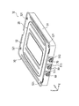
- FIG. 1 is a perspective view showing a battery module according to an embodiment of the present invention.
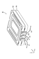
- FIG. 2 is a perspective view of the cell unit of the battery module as viewed from the tab lead-out side.
- FIG. 3 is a perspective view showing a single cell housed in the battery module according to the embodiment of the present invention.
- FIG. 4 is an exploded perspective view showing the internal configuration of the battery module according to the embodiment of the present invention.
- FIG. 5 is a diagram showing an electrical connection configuration of single cells constituting the battery module.
- FIG. 6 is a perspective view showing an assembled battery according to an embodiment of the present invention.
- FIG. 7 is a diagram illustrating a state before the external bus bar of the assembled battery according to the embodiment of the present invention is attached.
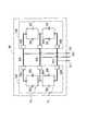
- FIG. 8 is a diagram showing an electrical connection configuration of unit cells housed in a battery module constituting the assembled battery according to the embodiment of the present invention.
- FIG. 9 is a plan view showing an assembled battery according to another embodiment of the present invention.
- the battery module 10 is a unit unit for assembling an assembled battery 90 described later, and includes a cell unit 20 including a plurality (four in this example) of single cells 30 (see FIG. 1). 2 and FIG. 3) and a case 50 for accommodating the cell unit 20 therein.
- the cell unit 20 includes four unit cells 30A to 30D (first unit cell 30A, second unit cell 30B, third unit cell 30C, and fourth unit cell 30D). And spacers 41 to 45 (first spacer 41, second spacer 42, third spacer 43, fourth spacer 44, and fifth spacer 45) attached to both ends of the unit cells 30A to 30D; An external output positive terminal 60, an external output negative terminal 70, and a voltage detection terminal 80 are provided.
- each single battery (cell) 30 includes, for example, a power generation element composed of an electrode laminate in which positive plates and negative plates are alternately laminated via separators and an electrolyte, and an exterior member 31. Is a flat lithium ion secondary battery having a substantially rectangular shape in plan view.
- the unit cell 30 is a general term for the unit cells 30A to 30D.
- the exterior member 31 of the unit cell 30 is composed of, for example, a laminate film in which a synthetic resin layer is laminated on both surfaces of a metal foil.
- the exterior member 31 accommodates the power generation element in a sealed state by heat-sealing four sides of the exterior member 31 in a state where the power generation element is accommodated to form a flange 32.
- the positive electrode plate and the negative electrode plate constituting the power generation element are connected to the positive electrode tab 34 and the negative electrode tab 35 led out from the outer member 31 in the outer member 31, respectively. Both of the negative electrode tabs 35 are led out to the outside from the short side on one end side in the longitudinal direction of the exterior member 31.
- a fixing hole 33 into which a fixing pin of a spacer, which will be described later, is inserted is formed on each short side of the flange 32 at both ends in the longitudinal direction.
- each of the electrode tabs 34 and 35 is a stack of unit cells 30A to 30D. It extends in the same direction in a direction orthogonal to the direction (Z direction).
- five spacers 41 to 45 are attached to the end portions of the unit cells 30A to 30D on the side where the electrode tabs 34 are led out.
- the spacers 41 to 45 define the pitch in the stacking direction of the cells 30A to 30D while being locked and connected in a stacked state.
- the flange 32 of the lowermost first unit cell 30 ⁇ / b> A is located between the first spacer 41 and the second spacer 42.
- the flange 32 of the second unit cell 30B is located between the second spacer 42 and the third spacer 43, and the flange 32 of the third unit cell 30C is connected to the third spacer 43 and the fourth spacer 43. It is located between the spacer 44 and the spacer 44.
- the flange 32 of the fourth unit cell 30 ⁇ / b> D is located between the fourth spacer 44 and the fifth spacer 45.
- five spacers are also attached to the end portions of the four unit cells 30A to 30D where the electrode tabs 34 and 35 are not led out.
- the first to fifth spacers 41 to 45 are connected to the external output positive terminal 60 and the external output negative terminal 70 which are output terminals of the battery module 10, and the unit constituting the battery module 10.
- a voltage detection terminal 80 used for voltage detection of the batteries 30A to 30D is derived.
- FIG. 4 is a perspective view showing the single battery 30 housed in the battery module 10.
- the positive tabs 34 of the first unit cell 30A and the second unit cell 30B are joined to the internal bus bar 61 electrically connected to the external output positive terminal 60 by ultrasonic welding or the like.
- the negative electrode tabs 35 of the first unit cell 30A and the second unit cell 30B are electrically connected to the voltage detection terminal 80 together with the positive electrode tab 34 of the third unit cell 30C and the fourth unit cell 30D.
- the internal bus bar 81 is joined by ultrasonic welding or the like, and the negative tabs 35 of the third unit cell 30C and the fourth unit cell 30D are electrically connected to the external output negative terminal 70.
- the internal bus bar 71 is joined by ultrasonic welding or the like.
- the external output positive terminal 60, the external output negative terminal 70, and the voltage detection terminal 80 are attached to the end portions of the cells 30A to 30D (specifically, the flange 32 on one end side in the longitudinal direction). 5 so that the external force input from the terminals 60, 70, 80 is not transmitted to the positive electrode tab 34 and the negative electrode tab 35 of each battery via the internal bus bars 61, 71, 81. It has become.
- L parallel M series (L and M are integers of 2 or more) means a circuit configuration in which M pieces of blocks in which L cells are connected in parallel (hereinafter referred to as parallel blocks) are connected in series. Means.
- the 2 parallel 2 series in this embodiment is a parallel block P1 in which the unit cell 30A and the unit cell 30B are connected in parallel, and a parallel block P2 in which the unit cell 30C and the unit cell 30D are connected in parallel. Means a circuit configuration connected to.
- the voltage detection terminal 80 is a terminal used for detecting the voltage of the single cells 30A to 30D constituting the battery module 10. Specifically, for the voltages of the first unit cell 30A and the second unit cell 30B, by using the external output positive terminal 60 and the voltage detection terminal 80, by measuring the voltage between these terminals, The voltage of the third unit cell 30C and the fourth unit cell 30D can be detected using the external output negative electrode terminal 70 and the voltage detection terminal 80, and the voltage between these terminals is measured. Thus, it can be detected.
- the external output positive terminal 60, the external output negative terminal 70, and the voltage detection terminal 80 are configured with terminals that can pass a current according to the battery capacity of the unit cell 30 housed in the battery module 10.
- the voltage detection terminal 80 a terminal having a rated current equal to or higher than the rated current of the external output positive terminal 60 and the external output negative terminal 70 (or the maximum value of the current that can be passed)
- the maximum allowable current is equal to or greater than that of the external output positive terminal 60 and the external output negative terminal 70).
- the voltage detection terminal 80 a terminal having a rated current equal to or higher than the rated currents of the external output positive terminal 60 and the external output negative terminal 70 may be used, but the external output positive terminal 60 and the external output negative terminal 70 By using the same terminal (that is, a terminal having the same rated current as that of the external output positive terminal 60 and the external output negative terminal 70), the manufacturing process of the battery module 10 can be simplified.
- the first spacer 41 is a substantially plate-like member made of a material having excellent electrical insulation such as a synthetic resin material. As shown in FIG. 4, on the upper surface of the first spacer 41, two fixing pins 411 to be inserted into the fixing holes 33 of the flange 32 of the first unit cell 30A are formed. A sleeve insertion hole 412 into which a sleeve 46 (see FIG. 2) is inserted is formed at both ends of the first spacer 41, and an engagement projecting upward is provided in the vicinity of the sleeve insertion hole 412. A nail 413 is formed. The engaging claw 413 engages with an engaging hole (not shown) formed on the lower surface of the second spacer 42, whereby the first spacer 41 and the second spacer 42 are connected.
- the second to fourth spacers 42 to 44 shown in FIG. 2 are also made of a material having excellent electrical insulation properties such as a synthetic resin material, and like the first spacer 41, the fixing pins and the sleeve insertion holes are formed. , And engaging claws are formed respectively.
- the fixing pins of the spacers 41 to 44 are inserted into the fixing holes 33 formed in the flanges 32 at both ends in the longitudinal direction of each unit cell 30, so that the surface direction (X direction or Y direction) of each unit cell 30 A to 30 D is obtained.
- Direction is defined.
- the fifth spacer 45 is also made of a material excellent in electrical insulation such as a synthetic resin material, but the fixing pin and the engaging claw are not formed, and only the sleeve insertion hole is formed.
- the second to fourth spacers 42 to 44 are not shown.
- the case 50 is a casing that protects the fragile cells 30A to 30D of the cell unit 20, and includes a bottomed box-like lower case 51 that is open at the top, an upper case 52 that closes the opening of the lower case 51, have.
- the lower case 51 and the upper case 52 are fixed to each other by winding the respective edges together.
- four bolt insertion holes 521 are formed in the upper case 52 at positions corresponding to the sleeves 46 of the cell unit 20.
- the lower case 51 is also formed with four bolt insertion holes at positions corresponding to the sleeves 46 of the cell unit 20.
- the position of the cell unit 20 is fixed in the case 50 by inserting bolts into the insertion holes 521 of the upper case 52, the sleeve 46 of the cell unit 20, and the insertion holes of the lower case 51.
- three cutouts 511, 512, and 513 are formed on the side surface of the lower case 51 in the longitudinal direction, and an external output positive terminal 60, an external output negative terminal 70, and a voltage detection terminal 80 is derived from these notches 511, 512 and 513, respectively.
- FIG. 6 is a perspective view showing the assembled battery 90 according to the present embodiment
- FIG. 7 is a view showing a state before the external bus bars 910, 920, 930 of the assembled battery 90 are attached. 6 and 7, the battery modules constituting the assembled battery 90 are the first battery module 10A and the second battery module 10B, respectively.
- the assembled battery 90 of the present embodiment includes a first battery module 10 ⁇ / b> A and a second battery module 10 ⁇ / b> B stacked to form a stacked body, and each of the battery modules 10 ⁇ / b> A and 10 ⁇ / b> B
- the external output positive terminals 60A and 60B, the external output negative terminals 70A and 70B, and the voltage detection terminals 80A and 80B are electrically connected by the external bus bars 910, 920, and 930, respectively.
- the external output positive terminals 60A and 60B of the battery modules 10A and 10B are the external bus bar 910
- the external output negative terminals 70A and 70B are the external bus bar 920
- the voltage detection terminals 80A and 80B are electrically connected by an external bus bar 930.
- Each terminal 60A, 60B, 70A, 70B, 80A, 80B and each external bus bar 910, 920, 930 are, for example, female screw portions formed on each terminal 60A, 60B, 70A, 70B, 80A, 80B. (Not shown) can be fixed using fixing bolts, whereby the terminals 60A, 60B, 70A, 70B, 80A, 80B and the external bus bars 910, 920, 930 are brought into close contact with each other. These can be electrically connected.
- the external bus bars 910, 920, and 930 are made of a material and shape (particularly, a cross-sectional shape) that allows a current to flow according to the battery capacity of the unit cell 30 housed in each of the battery modules 10A and 10B.
- the external bus bars 910, 920, 930 can be formed of a plate-like conductive member.
- voltage detection lines 911, 921, and 931 are connected to the external bus bars 910, 920, and 930, respectively, and these are connected to voltage sensors (not shown).
- FIG. 8 shows an electrical connection configuration of unit cells housed in the battery modules 10A and 10B constituting the assembled battery 90.
- the single cells constituting the battery module 10A are represented by single cells 30E to 30H
- the single cells constituting the battery module 10B are represented by single cells 30I to 30L.
- the battery modules 10A and 10B constituting the assembled battery 90 include external output positive terminals 60A and 60B, external output negative terminals 70A and 70B, and voltage detection terminals 80A and 80B, respectively.
- the 4 parallel 2 series refers to the parallel block P1 in which the single cells 30E and 30F in the battery module 10A and the single cells 30I and 30J in the battery module 10B are connected in parallel, and the battery module 10A. It means a circuit configuration in which the single cells 30G and 30H and the parallel block P2 in which the single cells 30K and 30L in the battery module 10B are connected in parallel are connected in series. That is, in the assembled battery 90, a parallel block of one battery module constituting the stacked body and a parallel block of another battery module constituting the stacked body are connected in parallel.
- the cells 30E, 30F, 30I, 30J. can be detected.
- the voltage detection line 921 connected to the external bus bar 920 and the voltage detection line 931 connected to the external bus bar 930 to a voltage sensor (not shown) can be detected.
- the battery modules 10A and 10B constituting the assembled battery 90 have a rated current equal to or higher than the rated currents of the external output positive terminals 60A and 60B and the external output negative terminals 70A and 70B.
- the voltage detection terminals 80A and 80B for detection are configured to be provided, and the voltage detection terminals 80A and 80B of the battery modules 10A and 10B are electrically connected by the external bus bar 930. Therefore, according to the present embodiment, the voltage detection line for detecting the terminal voltage of each of the single cells 30E to 30H and 30I to 30L constituting the battery modules 10A and 10B constituting the assembled battery 90 is the voltage detection line 911.
- the voltage detection terminals 80A and 80B are replaced with rated currents (or external output positive terminals 60A and 60B) that are equal to or higher than the rated currents of the external output positive terminals 60A and 60B and the external output negative terminals 70A and 70B. And a terminal having a maximum allowable current equal to or greater than the maximum allowable current of the external output negative terminals 70A and 70B. For this reason, out of the unit cells 30E to 30H and 30I to 30L constituting the battery modules 10A and 10B, for example, a unit cell constituting the battery module 10A (or 10B) has failed, thereby causing a failure.
- the voltage detection terminal 80B (or the other battery module 10B (or 10A)) 80A) can be effectively prevented from generating heat and damage.
- the cells constituting the battery modules 10A and 10B fail due to a short circuit, the power charged in the failed cells is output, which causes a relatively large current to flow instantaneously.
- a current equal to or higher than the rated current (or the maximum allowable current) of the voltage detection terminals 80A and 80B is passed through the external bus bar 930 that electrically connects the voltage detection terminals 80A and 80B. Is configured to be possible. Therefore, similarly to the above, even when a failure occurs in the single cells constituting the battery modules 10A and 10B, it is possible to effectively prevent the occurrence of problems such as heat generation, breakage, and disconnection of the external bus bar 930.
- the external output positive terminals 60A and 60B, the external output negative terminals 70A and 70B, and the voltage detection terminals 80A and 80B are fixed to the external bus bars 910, 920, and 930 using the fixing bolts. By connecting, the terminals 60A, 60B, 70A, 70B, 80A, 80B can be more easily electrically connected.
- the single battery 30 is the secondary battery of the present invention
- the external output positive terminals 60, 60A, 60B and the external output negative terminals 70, 70A, 70B are the output terminals of the present invention
- the external bus bar 910. , 920 and 930 correspond to the bus bars of the present invention, respectively.
- the battery module 10 having the connection configuration of 2 parallel 2 series is used, and the assembled battery 90 having the connection configuration of 4 parallel 2 series is illustrated by combining the two.
- the connection configuration of the battery modules constituting the battery and the number of battery modules constituting the assembled battery are not particularly limited and can be set as appropriate. That is, for example, as shown in FIG. 9, the battery module 10 has twelve battery modules 10, and the terminals 60, 70, and 80 of the twelve battery modules 10 are connected to each other by external bus bars 910 a, 920 a, and 930 a. It is good also as the assembled battery 90a which is 24 parallel 2 series by electrically connecting. As shown in FIG. 9, in the assembled battery 90a, voltage detection lines 911a, 921a, 931a are connected to the external bus bars 910a, 920a, 930a, respectively, and these are connected to a voltage sensor (not shown). ing.
- the number of voltage detection terminals 80 formed in the battery module 10 is a number corresponding to the number of series.
- the number of series is N (N is an integer of 3 or more)
- the number of voltage detection terminals 80 in the battery module 10 may be N ⁇ 1.
- the connection configuration of each battery module 10 is L parallel N series
- the number of battery modules constituting the battery stack is K (K is an integer of 2 or more)
- the battery pack is , K ⁇ L parallel N series connection configuration.
- the present invention provides voltage detection for detecting the voltage of each secondary battery housed in each battery module constituting an assembled battery by electrically connecting voltage detection terminals of a plurality of battery modules with a bus bar.
- the number of lines can be reduced.
Landscapes
- Chemical & Material Sciences (AREA)
- Chemical Kinetics & Catalysis (AREA)
- Electrochemistry (AREA)
- General Chemical & Material Sciences (AREA)
- Engineering & Computer Science (AREA)
- Manufacturing & Machinery (AREA)
- Battery Mounting, Suspending (AREA)
- Connection Of Batteries Or Terminals (AREA)
- Secondary Cells (AREA)
Abstract
Description
外部出力正極端子60、外部出力負極端子70、および電圧検出用端子80は、単電池30A~30Dの端部(具体的には、長手方向一端側のフランジ32)に装着された第1~第5のスペーサ41~45に固定され、各端子60,70,80から入力される外力が、内部ブスバ61,71,81を介して、各電池の正極タブ34および負極タブ35に伝達されないようになっている。
20…セルユニット
30A~30D…単電池
34…正極タブ
35…負極タブ
50…ケース
60,60A,60B…外部出力用正極端子
61…内部バスバ
70,70A,70B…外部出力用負極端子
71…内部バスバ
80,80A,80B…電圧検出用端子
81…内部バスバ
90,90a…組電池
910,920,930…外部バスバ
911,921,931…電圧検出線
Claims (5)
- 複数の二次電池が積層された積層体と、一対の出力端子と、前記二次電池の端子電圧を検出するために用いられ、前記一対の出力端子の定格電流以上の定格電流を有する電圧検出端子と、を各々備えた複数の電池モジュールと、
前記複数の電池モジュールの前記電圧検出端子同士を電気的に接続するバスバと、
を備えたことを特徴とする組電池。 - 請求項1に記載の組電池において、
前記バスバが、前記電圧検出端子の定格電流以上の電流を流すことができるものであることを特徴とする組電池。 - 請求項1または2に記載の組電池において、
前記バスバが、板状の導電性部材から構成されることを特徴とする組電池。 - 請求項1~3のいずれかに記載の組電池において、
前記複数の電池モジュールの各出力端子同士が、前記電圧検出端子同士を電気的に接続しているバスバとは異なるバスバにより、それぞれ電気的に接続されていることを特徴とする組電池。 - 電池モジュールを複数有する組電池を製造するための方法であって、
複数の二次電池を積層する工程と、
前記積層した複数の二次電池の電極タブを、前記電池モジュールの電気回路に応じて、それぞれ、一対の出力端子、および、前記二次電池の端子電圧を検出するために用いられ、前記一対の出力端子の定格電流以上の定格電流を有する電圧検出端子に電気的に接続することでセルユニットを得る工程と、
前記セルユニットを、ケースに収容することで、電池モジュールを得る工程と、
前記電池モジュールを、複数積層するとともに、前記複数の電池モジュールの前記電圧検出端子同士を、バスバにより電気的に接続する工程と、
を備えることを特徴とする組電池の製造方法。
Priority Applications (7)
| Application Number | Priority Date | Filing Date | Title |
|---|---|---|---|
| BR112012004425A BR112012004425A2 (pt) | 2009-08-28 | 2010-07-14 | "montagem de bateria e método de fabricação de motagem de bateria" |
| CN2010800362765A CN102473879A (zh) | 2009-08-28 | 2010-07-14 | 电池组及电池组的制造方法 |
| US13/390,189 US20120141847A1 (en) | 2009-08-28 | 2010-07-14 | Battery pack and method for manufacturing battery pack |
| KR1020127004000A KR101249184B1 (ko) | 2009-08-28 | 2010-07-14 | 조전지 및 조전지의 제조 방법 |
| MX2012001972A MX2012001972A (es) | 2009-08-28 | 2010-07-14 | Paquete de bateria y metodo para producir el paquete de bateria. |
| RU2012107105/07A RU2490755C1 (ru) | 2009-08-28 | 2010-07-14 | Блок батарей и способ изготовления блока батарей |
| EP10811625.2A EP2472635A4 (en) | 2009-08-28 | 2010-07-14 | ASSEMBLED BATTERY, AND METHOD FOR MANUFACTURING ASSEMBLED BATTERIES |
Applications Claiming Priority (2)
| Application Number | Priority Date | Filing Date | Title |
|---|---|---|---|
| JP2009197734A JP4877373B2 (ja) | 2009-08-28 | 2009-08-28 | 組電池および組電池の製造方法 |
| JP2009-197734 | 2009-08-28 |
Publications (1)
| Publication Number | Publication Date |
|---|---|
| WO2011024574A1 true WO2011024574A1 (ja) | 2011-03-03 |
Family
ID=43627685
Family Applications (1)
| Application Number | Title | Priority Date | Filing Date |
|---|---|---|---|
| PCT/JP2010/061914 Ceased WO2011024574A1 (ja) | 2009-08-28 | 2010-07-14 | 組電池および組電池の製造方法 |
Country Status (10)
| Country | Link |
|---|---|
| US (1) | US20120141847A1 (ja) |
| EP (1) | EP2472635A4 (ja) |
| JP (1) | JP4877373B2 (ja) |
| KR (1) | KR101249184B1 (ja) |
| CN (1) | CN102473879A (ja) |
| BR (1) | BR112012004425A2 (ja) |
| MX (1) | MX2012001972A (ja) |
| MY (1) | MY154198A (ja) |
| RU (1) | RU2490755C1 (ja) |
| WO (1) | WO2011024574A1 (ja) |
Cited By (2)
| Publication number | Priority date | Publication date | Assignee | Title |
|---|---|---|---|---|
| CN103325983A (zh) * | 2012-03-22 | 2013-09-25 | 株式会社东芝 | 电池以及电池的制造方法 |
| CN111564660A (zh) * | 2020-06-19 | 2020-08-21 | 义乌易换骑电池有限公司 | 一种防止电压采集干扰锂电池组 |
Families Citing this family (20)
| Publication number | Priority date | Publication date | Assignee | Title |
|---|---|---|---|---|
| JP5500518B2 (ja) * | 2009-06-10 | 2014-05-21 | 矢崎総業株式会社 | 電流センサ付きバッテリーターミナル |
| JP5737046B2 (ja) * | 2011-08-10 | 2015-06-17 | 株式会社オートネットワーク技術研究所 | 電池配線モジュール |
| JP5836147B2 (ja) * | 2012-02-08 | 2015-12-24 | 株式会社ニフコ | バッテリー体の外部接続部のカバー |
| JP2014191968A (ja) * | 2013-03-27 | 2014-10-06 | Toyoda Gosei Co Ltd | 電池装置 |
| JP6135246B2 (ja) | 2013-03-29 | 2017-05-31 | 株式会社Gsユアサ | 蓄電装置 |
| KR102063601B1 (ko) * | 2013-06-21 | 2020-01-08 | 에스케이이노베이션 주식회사 | 전지 모듈 |
| US10205140B2 (en) | 2014-02-19 | 2019-02-12 | Delta Electronics, Inc. | Cell and manufacture method thereof |
| US10084218B2 (en) | 2014-05-09 | 2018-09-25 | Lg Chem, Ltd. | Battery pack and method of assembling the battery pack |
| US10770762B2 (en) | 2014-05-09 | 2020-09-08 | Lg Chem, Ltd. | Battery module and method of assembling the battery module |
| US9786894B2 (en) * | 2014-11-03 | 2017-10-10 | Lg Chem, Ltd. | Battery pack |
| KR101898185B1 (ko) * | 2014-11-11 | 2018-09-12 | 광동 오포 모바일 텔레커뮤니케이션즈 코포레이션 리미티드 | 전원 어댑터, 단말기 및 충전 시스템 |
| US20170025661A1 (en) * | 2015-07-23 | 2017-01-26 | Ford Global Technologies, Llc | Sensor lead securing assembly and method |
| US9960465B2 (en) | 2015-07-30 | 2018-05-01 | Lg Chem, Ltd. | Battery pack |
| WO2017068709A1 (ja) | 2015-10-22 | 2017-04-27 | 日産自動車株式会社 | 組電池 |
| JP6567620B2 (ja) | 2017-10-03 | 2019-08-28 | カルソニックカンセイ株式会社 | 組電池の製造方法及び組電池 |
| JP6479924B1 (ja) | 2017-10-03 | 2019-03-06 | カルソニックカンセイ株式会社 | 組電池の製造方法及び組電池 |
| KR102699573B1 (ko) * | 2019-05-14 | 2024-08-27 | 에스케이온 주식회사 | 배터리 모듈 |
| JP7647261B2 (ja) * | 2021-04-08 | 2025-03-18 | トヨタ自動車株式会社 | 電池パックの製造方法 |
| KR102637525B1 (ko) * | 2021-10-26 | 2024-02-19 | 주식회사 엘지에너지솔루션 | 배터리 모듈 및 이를 포함한 배터리 팩 |
| EP4535551A4 (en) * | 2022-05-25 | 2026-03-11 | Nissan Motor | BATTERY MODULE |
Citations (5)
| Publication number | Priority date | Publication date | Assignee | Title |
|---|---|---|---|---|
| JP2007012584A (ja) * | 2005-06-01 | 2007-01-18 | Nissan Motor Co Ltd | 組電池およびこれを搭載した車両 |
| JP2007059088A (ja) | 2005-08-22 | 2007-03-08 | Nissan Motor Co Ltd | 組電池 |
| JP2007265945A (ja) * | 2006-03-30 | 2007-10-11 | Tokyo R & D Co Ltd | ラミネートセル集積型バッテリ及びバッテリモジュール |
| JP2009112111A (ja) * | 2007-10-30 | 2009-05-21 | Toshiba Corp | 電池パック、充電器及び電池パックシステム |
| JP2009197734A (ja) | 2008-02-22 | 2009-09-03 | Toyota Motor Corp | 太陽熱エネルギー変換方法 |
Family Cites Families (12)
| Publication number | Priority date | Publication date | Assignee | Title |
|---|---|---|---|---|
| SU121828A1 (ru) * | 1958-05-30 | 1958-11-30 | Н.М. Емельянов | Устройство дл соединени положительных свинцовых аккумул торных пластин при их формировании |
| RU2187865C2 (ru) * | 1997-01-13 | 2002-08-20 | Овоник Бэттери Компани, Инк. | Механические и тепловые усовершенствования в никельметаллгидридных батареях, модулях батарей и пакетах батарей |
| KR100456857B1 (ko) * | 2002-11-25 | 2004-11-10 | 현대자동차주식회사 | 하이브리드 전기 차량의 전지 셀간 커넥팅 장치 |
| JP4581326B2 (ja) * | 2002-12-27 | 2010-11-17 | 日産自動車株式会社 | 積層型電池の製造装置 |
| JP4238645B2 (ja) * | 2003-06-12 | 2009-03-18 | 日産自動車株式会社 | バイポーラ電池 |
| JP3894182B2 (ja) * | 2003-10-10 | 2007-03-14 | 日産自動車株式会社 | 組電池 |
| KR100746485B1 (ko) * | 2004-12-24 | 2007-08-06 | 주식회사 엘지화학 | 이차전지 모듈용 센싱 보드 어셈블리 |
| KR100891079B1 (ko) * | 2005-02-07 | 2009-03-30 | 주식회사 엘지화학 | 전지 모듈용 전지 카트리지 연결 시스템 |
| US7960943B2 (en) * | 2006-11-17 | 2011-06-14 | Cobasys, Llc | Modular battery system having battery monitoring and data collection capability |
| JP4379467B2 (ja) * | 2006-12-11 | 2009-12-09 | 日産自動車株式会社 | 電池モジュール |
| JP5018203B2 (ja) * | 2007-04-19 | 2012-09-05 | パナソニック株式会社 | 蓄電ユニット |
| CA2646925A1 (en) * | 2007-12-12 | 2009-06-12 | Westward Industries Ltd. | Battery management system |
-
2009
- 2009-08-28 JP JP2009197734A patent/JP4877373B2/ja not_active Expired - Fee Related
-
2010
- 2010-07-14 KR KR1020127004000A patent/KR101249184B1/ko not_active Expired - Fee Related
- 2010-07-14 MY MYPI2012000666A patent/MY154198A/en unknown
- 2010-07-14 BR BR112012004425A patent/BR112012004425A2/pt not_active IP Right Cessation
- 2010-07-14 US US13/390,189 patent/US20120141847A1/en not_active Abandoned
- 2010-07-14 RU RU2012107105/07A patent/RU2490755C1/ru not_active IP Right Cessation
- 2010-07-14 CN CN2010800362765A patent/CN102473879A/zh active Pending
- 2010-07-14 WO PCT/JP2010/061914 patent/WO2011024574A1/ja not_active Ceased
- 2010-07-14 MX MX2012001972A patent/MX2012001972A/es active IP Right Grant
- 2010-07-14 EP EP10811625.2A patent/EP2472635A4/en not_active Withdrawn
Patent Citations (5)
| Publication number | Priority date | Publication date | Assignee | Title |
|---|---|---|---|---|
| JP2007012584A (ja) * | 2005-06-01 | 2007-01-18 | Nissan Motor Co Ltd | 組電池およびこれを搭載した車両 |
| JP2007059088A (ja) | 2005-08-22 | 2007-03-08 | Nissan Motor Co Ltd | 組電池 |
| JP2007265945A (ja) * | 2006-03-30 | 2007-10-11 | Tokyo R & D Co Ltd | ラミネートセル集積型バッテリ及びバッテリモジュール |
| JP2009112111A (ja) * | 2007-10-30 | 2009-05-21 | Toshiba Corp | 電池パック、充電器及び電池パックシステム |
| JP2009197734A (ja) | 2008-02-22 | 2009-09-03 | Toyota Motor Corp | 太陽熱エネルギー変換方法 |
Non-Patent Citations (1)
| Title |
|---|
| See also references of EP2472635A4 |
Cited By (2)
| Publication number | Priority date | Publication date | Assignee | Title |
|---|---|---|---|---|
| CN103325983A (zh) * | 2012-03-22 | 2013-09-25 | 株式会社东芝 | 电池以及电池的制造方法 |
| CN111564660A (zh) * | 2020-06-19 | 2020-08-21 | 义乌易换骑电池有限公司 | 一种防止电压采集干扰锂电池组 |
Also Published As
| Publication number | Publication date |
|---|---|
| JP4877373B2 (ja) | 2012-02-15 |
| EP2472635A4 (en) | 2013-09-18 |
| BR112012004425A2 (pt) | 2017-05-30 |
| MX2012001972A (es) | 2012-03-29 |
| KR20120048631A (ko) | 2012-05-15 |
| CN102473879A (zh) | 2012-05-23 |
| US20120141847A1 (en) | 2012-06-07 |
| KR101249184B1 (ko) | 2013-04-03 |
| JP2011049080A (ja) | 2011-03-10 |
| MY154198A (en) | 2015-05-15 |
| EP2472635A1 (en) | 2012-07-04 |
| RU2490755C1 (ru) | 2013-08-20 |
Similar Documents
| Publication | Publication Date | Title |
|---|---|---|
| JP4877373B2 (ja) | 組電池および組電池の製造方法 | |
| JP6507136B2 (ja) | 電池パック | |
| JP6079785B2 (ja) | 組電池および組電池の製造方法 | |
| JP5657273B2 (ja) | 積層型電池、電池モジュール及び積層型電池の製造方法 | |
| CN101496194B (zh) | 使用两个或更多个单元电池的高容量电池组电池 | |
| JP4800323B2 (ja) | 二次電池モジュール用センシングボードアセンブリ | |
| EP2672284A2 (en) | Voltage sensing assembly and battery module having same | |
| JP2011243561A (ja) | バッテリーパック | |
| CN101490871A (zh) | 中型或大型电池组模块 | |
| JP2011243426A (ja) | 電池パック及び電池パック用コネクタ | |
| JP5407576B2 (ja) | コネクタモジュール | |
| KR20120074415A (ko) | 신규한 구조의 단위모듈 및 이를 포함하는 전지모듈 | |
| WO2019131358A1 (ja) | 電池パック | |
| EP2874204B1 (en) | Battery assembly | |
| WO2014103709A1 (ja) | 電池モジュールおよび組電池 | |
| CN109980143B (zh) | 蓄电装置 | |
| KR20120074426A (ko) | 신규한 구조의 단위모듈 및 이를 포함하는 전지모듈 | |
| JP2014060111A (ja) | 組電池 | |
| JP7835900B2 (ja) | 電池モジュール | |
| JP7543387B2 (ja) | セル積層体 | |
| JP5114944B2 (ja) | 組電池 | |
| JP2010205495A (ja) | 電池モジュールの製造方法およびその製造方法 |
Legal Events
| Date | Code | Title | Description |
|---|---|---|---|
| WWE | Wipo information: entry into national phase |
Ref document number: 201080036276.5 Country of ref document: CN |
|
| 121 | Ep: the epo has been informed by wipo that ep was designated in this application |
Ref document number: 10811625 Country of ref document: EP Kind code of ref document: A1 |
|
| WWE | Wipo information: entry into national phase |
Ref document number: 13390189 Country of ref document: US |
|
| ENP | Entry into the national phase |
Ref document number: 20127004000 Country of ref document: KR Kind code of ref document: A |
|
| WWE | Wipo information: entry into national phase |
Ref document number: MX/A/2012/001972 Country of ref document: MX |
|
| WWE | Wipo information: entry into national phase |
Ref document number: 12012500333 Country of ref document: PH |
|
| WWE | Wipo information: entry into national phase |
Ref document number: 428/KOLNP/2012 Country of ref document: IN |
|
| WWE | Wipo information: entry into national phase |
Ref document number: 2012107105 Country of ref document: RU Ref document number: 2010811625 Country of ref document: EP |
|
| NENP | Non-entry into the national phase |
Ref country code: DE |
|
| WWE | Wipo information: entry into national phase |
Ref document number: 1201000822 Country of ref document: TH |
|
| REG | Reference to national code |
Ref country code: BR Ref legal event code: B01A Ref document number: 112012004425 Country of ref document: BR |
|
| ENP | Entry into the national phase |
Ref document number: 112012004425 Country of ref document: BR Kind code of ref document: A2 Effective date: 20120228 |