WO2011027634A1 - 小腸内視鏡練習模型 - Google Patents
小腸内視鏡練習模型 Download PDFInfo
- Publication number
- WO2011027634A1 WO2011027634A1 PCT/JP2010/062595 JP2010062595W WO2011027634A1 WO 2011027634 A1 WO2011027634 A1 WO 2011027634A1 JP 2010062595 W JP2010062595 W JP 2010062595W WO 2011027634 A1 WO2011027634 A1 WO 2011027634A1
- Authority
- WO
- WIPO (PCT)
- Prior art keywords
- small intestine
- simulated
- practice model
- endoscope
- case
- Prior art date
- Legal status (The legal status is an assumption and is not a legal conclusion. Google has not performed a legal analysis and makes no representation as to the accuracy of the status listed.)
- Ceased
Links
Images






Classifications
-
- G—PHYSICS
- G09—EDUCATION; CRYPTOGRAPHY; DISPLAY; ADVERTISING; SEALS
- G09B—EDUCATIONAL OR DEMONSTRATION APPLIANCES; APPLIANCES FOR TEACHING, OR COMMUNICATING WITH, THE BLIND, DEAF OR MUTE; MODELS; PLANETARIA; GLOBES; MAPS; DIAGRAMS
- G09B23/00—Models for scientific, medical, or mathematical purposes, e.g. full-sized devices for demonstration purposes
- G09B23/28—Models for scientific, medical, or mathematical purposes, e.g. full-sized devices for demonstration purposes for medicine
- G09B23/285—Models for scientific, medical, or mathematical purposes, e.g. full-sized devices for demonstration purposes for medicine for injections, endoscopy, bronchoscopy, sigmoidscopy, insertion of contraceptive devices or enemas
-
- A—HUMAN NECESSITIES
- A61—MEDICAL OR VETERINARY SCIENCE; HYGIENE
- A61B—DIAGNOSIS; SURGERY; IDENTIFICATION
- A61B1/00—Instruments for performing medical examinations of the interior of cavities or tubes of the body by visual or photographical inspection, e.g. endoscopes; Illuminating arrangements therefor
- A61B1/00002—Operational features of endoscopes
- A61B1/00057—Operational features of endoscopes provided with means for testing or calibration
Definitions
- the present invention relates to a small intestine endoscopic practice model including a case having a space for a simulated abdominal cavity and a simulated small intestine accommodated in the space for the simulated abdominal cavity.
- the digestive tract of a living body is connected from the mouth to the esophagus, stomach, small intestine (this small intestine is divided into duodenum, jejunum and ileum) and large intestine, and reaches the anus.
- a doctor observes the inside of the digestive tract with an endoscope and performs treatment such as hemostasis and polyp excision on the inside.
- the object of these observations and treatments has been limited to a site relatively close to the mouth or anus, which is the insertion site of the endoscope.
- the stomach and a part of the duodenum are the target range of observation and treatment.
- the range up to the large intestine is the target range of observation and treatment.
- capsule endoscopes that are swallowed from the mouth for the purpose of observing the small intestine have been put into practical use. And this capsule endoscope has little pain given to a patient at the time of its use.
- this capsule endoscope has the disadvantages that it can only be observed and cannot be used for patients with suspected intestinal obstruction or stenosis, such as hemostasis or polyp excision, or incapable of biopsy. . For this reason, the conventional endoscope is not replaced by the capsule endoscope, and both are considered to be used according to the purpose in the future.
- the small intestine is inserted into the small intestine due to the fact that the endoscope is located in the fold further than the organ that was previously inserted, and the small intestine itself is a tortuous luminal organ.
- the operation of proceeding to the site is very difficult even using a recently developed balloon endoscope or the like. For this reason, if a person who is not proficient in the operation of an endoscope operates, a sufficiently wide range of the small intestine cannot be observed, the purpose cannot be achieved, or the intestinal tract is not used for dangerous operations. There is a risk of damage. Therefore, a practice model for practicing the operation of inserting the endoscope into the small intestine is becoming necessary.
- the present invention provides a small intestine endoscopic practice model including a case having a space for a simulated abdominal cavity and a simulated small intestine accommodated in the space for the simulated abdominal cavity.
- a plurality of longitudinal elastic bodies for applying an elastic force are provided, and one end side of each of the longitudinal elastic bodies is respectively connected to the plurality of first attachment portions in the vicinity of the plurality of locations on the simulated small intestine side.
- the small intestine endoscope practice model is characterized in that each of the other ends of the longitudinal elastic body is attached to a second attachment part on the case side.
- a doctor inserts an endoscope into the small intestine by appropriately selecting the positions of the first mounting portion and the second mounting portion, and the endoscope is inserted into the small intestine. It is possible to provide an excellent practice model that can be mastered in a short period of time in observation and treatment.
- the elastic forces applied by the plurality of longitudinal elastic bodies are respectively applied. It is preferable to approximate the restoring force to the original position of the small intestine by the mesentery of the living body.
- the plurality of longitudinal elastic bodies are gathered together toward a substantially common location from one end side to the other end side thereof, and the case Preferably it is attached to one or more of the second attachments on the side.
- the other end part side of the said several longitudinal elastic body is attached to the said 2nd attachment part common on the said case side.
- the elastic force applied to the simulated small intestine by the plurality of longitudinal elastic bodies is substantially along the length direction of the plurality of longitudinal elastic bodies.
- a tensile force is preferred.
- each of the plurality of longitudinal elastic bodies is preferably a rubber string and / or a coil spring.
- each of the plurality of longitudinal elastic bodies is preferably a rubber string.
- the number of the plurality of longitudinal elastic bodies is preferably in the range of 3 to 10 (more preferably 4 to 8).
- the mounting interval between the plurality of first mounting portions is converted into a length in the axial direction when the virtual axis of the simulated small intestine is linearly arranged.
- it is preferably in the range of 15 to 30 cm (more preferably 18 to 24 cm).
- the load at the time of 100% elongation of the longitudinal elastic body is in the range of 0.15 to 0.30 kg weight (preferably 0.20 to 0.24 kg weight). Preferably there is.
- the ninth aspect since it is possible to obtain a feeling very close to that when the endoscope is actually inserted into the small intestine of a living body, it is further necessary to become familiar with the practical operation of the endoscope. Simple.
- the small intestine endoscopic practice model can be comprised so that operation which inserts an endoscope from the anus to the small intestine via the large intestine can be practiced.
- the small intestine endoscope practice model is configured to practice an operation of inserting the endoscope from the mouth through the esophagus and stomach into the small intestine. it can.
- a simulated large intestine accommodated in a space for the simulated abdominal cavity a sheet laid on the abdominal surface side of the simulated large intestine, and an opening provided in the sheet.
- the simulated small intestine is disposed on the abdominal surface side of the sheet, is connected to the simulated large intestine through the opening, and the simulated large intestine and the open of the simulated small intestine are provided. It is preferable that the portion on the back side of the hole is substantially covered with the sheet.
- the movement of the portion of the simulated small intestine that is close to the connection portion with the simulated large intestine is restricted, and the portion of the simulated small intestine that is away from the connection portion with the simulated large intestine is relatively It can move freely and smoothly. For this reason, a feeling closer to that when the endoscope is actually inserted into the small intestine from the anus of the living body via the large intestine is obtained, and it is possible to become familiar with the more practical operation of the endoscope. it can.
- the plurality of first attachment portions include a location on the abdominal surface side than the seat and a location on the back side from the seat, and more than the seat.
- the longitudinal elastic body having the one end side attached to the position on the abdominal surface side passes through the abdominal surface side than the sheet and extends to the second attachment portion, and is located on the back side of the sheet. It is preferable that the longitudinal elastic body to which the one end portion side is attached extends to the second attachment portion through the back side from the sheet.
- a plurality of first attachment portions can be selected at substantially the same position as when the sheet is not laid. The movement can be prevented from being substantially impeded by the seat. For this reason, a feeling closer to that when the endoscope is actually inserted into the small intestine from the anus of the living body via the large intestine is obtained, and it is possible to become familiar with the more practical operation of the endoscope. it can.
- the simulated small intestine is configured to be able to contact the inner surface of the simulated abdominal cavity over substantially the entire length in the length direction thereof, and is inserted into the simulated small intestine.
- the inner surface may have a smoothness so that the simulated small intestine pushed from the inside by the endoscope can move along the inner surface of the simulated abdominal cavity.
- the case has a top surface sheet attached to the case body so that the case body and the top surface opening formed on the upper surface of the case body can be closed and opened. It is preferable to provide a member.
- the case includes an opaque lower case member, a transparent upper case member that is detachably coupled to the lower case member, and an upper surface of the upper case member. It is preferable to include a top sheet member attached to the upper case member so that the formed top surface opening can be closed and opened.
- the lower case member includes a shelf portion and a rising wall portion for forming a space for the simulated abdominal cavity. According to the fifteenth to seventeenth aspects, a case in which a simulated living body such as a simulated small intestine is not exposed to the outside and exposed to external dust or the like and is easy to handle can be manufactured at low cost.
- a mounting plate or mounting table for mounting the case, and the case is mounted on the mounting plate or mounting table in a substantially horizontal state.
- an engagement mechanism that selectively enables the case to be mounted on the mounting plate or mounting table in a substantially vertical state.
- the engagement mechanism is provided on the other of the plurality of engagement pins provided on one of the case and the mounting plate or the mounting table, and the case and the mounting plate or the mounting table.
- a plurality of engagement holes provided.
- the small intestine endoscopic practice model that is in a state similar to the state in which the living body faces upward and lies down (that is, the supine position) is practiced for operating the endoscope.
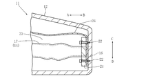
- FIG. 2 is a perspective view of the small intestine endoscope practice model shown in FIG. 1 in a state where most of the simulated small intestine is removed. It is a longitudinal cross-sectional view near the anus of the small intestine endoscope practice model shown in FIG.
- FIG. 3 is a front view of the vicinity of a connecting portion between a small intestine and a large intestine in a state before an endoscope is inserted into a living body, and is a first reference diagram for explaining the first embodiment.
- FIG. 3 is a front view of the vicinity of a connecting portion between a small intestine and a large intestine in a state before an endoscope is inserted into a living body, and is a first reference diagram for explaining the first embodiment.
- FIG. 7 is a front view of the vicinity of a connection portion between the small intestine and the large intestine in a state where the endoscope is inserted into the small intestine via the anus and large intestine of a living body, and is a second view for explaining the first embodiment.
- It is a reference figure.
- It is a perspective view of the small intestine endoscope practice model with a mounting board by the 3rd Example to which this invention is applied.
- It is a longitudinal cross-sectional view of the small intestine endoscope practice model with a mounting board shown in FIG.
- FIG. 1 is a perspective view in another use condition of the small intestine endoscope practice model with a mounting board shown in FIG.
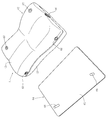
- FIG. 7 is a perspective view of the small intestine endoscope practice model with the placement plate shown in FIG. 6 in a state where the upper and lower portions are repeated after the small intestine endoscope practice model is separated from the placement plate. It is a perspective view of the small intestine endoscope practice model with a mounting board shown in FIG. 6 in a storage state or a transport state.
- the portion of the small intestine except the duodenum is attached to the mesentery extending from the posterior wall of the abdominal cavity. Since this mesentery is a very flexible and stretchable membrane-like structure, when force is applied to the small intestine, the small intestine can move in the abdominal cavity.
- an endoscope specifically, an insertion tube portion of the endoscope
- the small intestine is pushed from the inside of the small intestine itself by an endoscope, and is extended outward of the body.
- a force to pull the stretched small intestine back toward the center of the body is applied to the small intestine.
- it is very important in practicing the operation of the endoscope that such a force to pull back the small intestine is also applied to the simulated small intestine.
- tags in other words, cloth, synthetic resin
- the practice model housing in other words, the case or the case body.
- the position where such a longitudinal elastic body is attached to the practice model case imitates that the living body's mesentery extends from the rear wall of the abdominal cavity, and the simulated small intestine is accommodated in the practice model case. It may be a concave simulated abdominal cavity.
- the inventor of the present invention also finds that, if the direction in which the simulated small intestine is pulled substantially matches the case of the living body, there is no problem in practical use, and it can be found on the outer surface of the practice model case. It was.
- the elasticity of the longitudinal elastic body is determined by the load (hereinafter referred to as “100% stretched”) when the distance between the marks (that is, the indicia) provided at intervals of 10 cm in the extending direction of the longitudinal elastic body is extended to 20 cm.
- the weight of 0.15 to 0.30 kg is appropriate, and the weight of 0.20 to 0.24 kg is more appropriate.
- the load at the time of 100% elongation is 0.47 kg weight, for example, the feeling when the endoscope is inserted into the simulated small intestine is the feeling when the endoscope is inserted into the small intestine of a living body. Obviously it was different.
- the longitudinal elastic body may include a rubber string, a coil spring made of metal or soft synthetic resin, and the like.
- the simulated large intestine necessarily exists, and the simulated small intestine needs to be connected to the simulated large intestine.
- a portion of the small intestine that is relatively close to the large intestine is folded zigzag in the pelvic cavity.
- the practice model also has a part of the simulated small intestine folded on the lower limb side of the simulated abdominal cavity.
- the endoscope is inserted from the simulated large intestine into the simulated small intestine, the simulated small intestine greatly protrudes from the simulated abdominal cavity, so that the practice model is greatly different from the living body.
- a flexible sheet is laid on the entire simulated abdominal cavity so as to cover the simulated large intestine, and a part of the simulated small intestine is accommodated under this sheet. Then, the remaining part of the simulated small intestine is put out on the sheet through a hole (in other words, an opening) formed in one position of the sheet, and is arranged on this sheet.
- the small intestine in the abdominal cavity other than in the pelvic cavity moves relatively greatly, so in the practice model, the remaining part of the simulated small intestine is arranged on the sheet as described above in order to achieve this. .
- the presence of the sheet allows the simulated small intestine to be moved without being interfered with the simulated large intestine.
- the longitudinal elastic body is attached to the simulated small intestine via the attachment piece, there is a limitation of movement due to this.
- the longitudinal elastic body and the sheet are used in this way, the movement of the simulated small intestine in a portion close to the simulated large intestine and in the pelvic cavity in the living body is greatly limited by both the sheet and the longitudinal elastic body. . Further, in the living body, in the portion of the simulated small intestine other than in the pelvic cavity, a relatively free movement of the simulated small intestine due to the limitation of only the longitudinal elastic body is reproduced. It has also been found by the inventors of the present invention that the difficulty of inserting an endoscope can be adjusted by adjusting the amount of simulated small intestine that is folded under a flexible sheet. It was.
- the practice model can be used for practice of endoscope operation according to a wide range of purposes.
- a separately prepared portion of the simulated small intestine may be provided with various lesions or provided with a stenosis that is difficult to insert an endoscope.
- an outward or inward collar (in other words, an annular convex portion) is provided on one of the connection part of the non-exchange part of the simulated small intestine and the connection part of the exchange part, An inward or outward annular recess may be provided on the other of these connecting portions.
- the non-exchange part and exchange part of a simulated small intestine are connected by elastically deforming at least one of these connection parts, and carrying out uneven fitting of an annular concave part and an annular convex part. can do.
- first to third examples of the present invention are divided into “1, first example”, “2, second example” and “3, third example”, This will be described more specifically.
- the present invention is not limited to these first to third embodiments.
- FIGS. 1 to 3 show a practice model 11 according to a first embodiment for practicing the operation of inserting an endoscope from the anus through the large intestine into the small intestine.
- the case 12 of the practice model 11 imitates the size and shape of the abdomen of the human body (in other words, from the vicinity of the diaphragm to the vicinity of the buttocks).
- arrows A and B indicate the chest side and the lower limb side of the practice model 11 corresponding to the chest side and the lower limb side of the human body, respectively.
- Arrows C and D indicate the abdominal surface side and the back surface side of the practice model 11 corresponding to the abdominal surface side and the back surface side of the human body, respectively.
- arrows E and F indicate the left and right sides of the practice model 11 corresponding to the left and right sides of the human body, respectively.
- the case 12 does not need to imitate the softness of the human body.
- the case 12 is made of hard plastic in consideration of convenience when carrying the practice model 11.
- a concave simulated abdominal cavity 15 that imitates the abdominal cavity of a human body is provided on the ventral side C of the case 12 in order to accommodate the simulated small intestine 13 and the simulated large intestine 14.
- a simulated anus 16 is opened near the center of the side surface of the lower limb side B of the case 12.
- An endoscope (specifically, an endoscope insertion portion and an endoscope insertion overtube) can be inserted from the simulated anus 16.
- the simulated anus 16 is connected to a simulated rectum 17 of the simulated large intestine 14 as described later.
- the simulated abdominal cavity 15 of the case 12 can arrange the simulated large intestine 14 in the same shape as the large intestine of the human body.
- the middle part of the ascending colon of the simulated large intestine 14 and the middle part of the descending colon of the simulated large intestine 14 are bonded to the respective plate-like platforms. These platforms are fixed to the bottom surface of the simulated abdominal cavity 15 with screws.
- the simulated large intestine 14 is made of silicone rubber in order to approximate the flexibility of the large intestine of a living body.
- the simulated large intestine 14 is formed into a tubular shape having an annular fold, similar to the large intestine of a living body, and has a thickness of about 0.7 to 1.0 mm.
- the simulated rectum 17 of the simulated large intestine 14 is attached and fixed coaxially with the simulated anus 16 near the center of the inner surface of the lower limb side B of the case 12 by a pressing plate 21 and screws 22 as shown in FIG. ing.
- FIG. 3 On the simulated large intestine 14 (in other words, on the abdominal surface C), as shown in FIG. 3, as shown in FIG. 3, a flexible and slip for covering the simulated large intestine 14 and forming a simulated pelvic cavity 23 between the wall of the case 12.
- a good vinyl chloride sheet 24 is laid.
- the sheet 24 is fixed to the case 12 with a string 25 on the chest side A.
- seat 24 is being fixed to the center vicinity of the inner surface of the lower limb side B of the case 12 by the press board 21 and the screw 22, as shown in FIG.
- most of the simulated small intestine 13 on the seat 24 is removed from the practice model 11, so that the structure under the seat 24 is clearly shown by broken lines.
- the simulated small intestine 13 is made of silicone rubber in order to approximate the flexibility of the small intestine of a living body.
- the simulated small intestine 13 is molded into a tubular shape having an annular fold, similar to the small intestine of a living body, and the thickness thereof is about 0.5 to 0.7 mm. Further, since a lesioned part and a polyp are provided in the simulated small intestine 13, by using this practice model 11, it is possible to acquire techniques for treatment such as observation of the lesioned part and removal of the polyp. .
- a portion of the simulated small intestine 13 from the connecting portion 28 to the simulated large intestine 14 to a length of about 20 cm is arranged under the sheet 24 so as to be folded or drawn in a loop as shown in FIG. Yes.
- An opening 26 is provided in the sheet 24.
- a portion of the simulated small intestine 13 having a length of about 20 cm from the connection portion 28 to the simulated large intestine 14 passes through the opening 26.
- the simulated small intestine 13 beyond the opening 26 can be disposed on the sheet 24 in an appropriately winding state. This arrangement can be made freely on the sheet 24.
- the entire length of the simulated small intestine 13 is sufficient to be about 1 to 1.5 m. This is because even if the entire length of the simulated small intestine 13 is longer than this, the operation procedure for inserting the endoscope is the same, and it is not necessary to be longer than that. .
- a total of five attachment pieces 27 are attached to the outer surface of the simulated small intestine 13 at appropriate intervals.
- This appropriate attachment interval is 15 to 30 cm in terms of the length in the length direction of the simulated small intestine 13 (in other words, the axial direction when the virtual axis of the simulated small intestine 13 is linearly arranged). Is preferable, and a range of 18 to 24 cm is more preferable.
- These attachment pieces 27 are provided with holes (in other words, openings) 31, and one end of each rubber string 32 is attached to each opening 31. Further, at a position on the right side F of the case 12 and the chest side A, a rubber string attaching portion 33 to which the other end portion of the elastic cord 32 can be attached is provided.
- the rubber string attachment portion 33 is configured by an attachment having an insertion hole through which five rubber strings 32 are inserted in common. Then, after the five rubber strings 33 are inserted into the insertion holes, the five elastic strings 33 are attached to the fixture 33, or knots for retaining are attached.
- One of the attachment pieces 27 is attached to a portion of the simulated small intestine 13 that is folded under the sheet 24 or drawn in a loop.
- the elastic band 32 attached to the attachment piece 27 passes under the sheet 24 and exits from the gap between the side edge of the sheet 24 and the simulated abdominal cavity 15 and then onto the elastic band attachment portion 33. It is attached.
- the remaining four attachment pieces 27 are attached to a portion of the simulated small intestine 13 disposed on the sheet 24.
- the rubber string 32 attached to these four attachment pieces 27 passes over the sheet 24 and is attached to the rubber string attachment part 33.
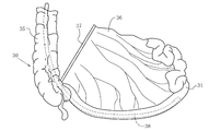
- a portion of the small intestine 34 that is relatively close to the large intestine 35 is attached to the mesentery 36 that extends from the rear wall of the abdominal cavity in a state of being folded zigzag. .
- the mesentery 36 is attached to the rear wall of the abdominal cavity at the right side of the rear wall of the abdominal cavity (that is, the right side as viewed from the living body itself) and at the chest side, and is attached to the small intestine 35 from the attachment part 37. It is growing towards. For this reason, as shown in FIG. 5, a force retracted by the mesentery 36 toward the right chest acts on the small intestine 34 extended by inserting the endoscope 38.
- the rubber string 32 imitates the function of the mesentery 36. Accordingly, in the practice model 11, the elastic band attaching portion 33 is also positioned on the right side F of the case 12 and on the chest side A so that the force for pulling back the simulated small intestine 13 works in the same direction as the force generated by the mesentery 36. Is provided.
- the diameter of the elastic band 32 is 3 mm, and the load at 100% elongation is 0.22 kg weight.
- Each length of the elastic band 32 is set at a distance from each elastic band attaching portion 33 to the attaching piece 27 in a state where the simulated small intestine 13 is roughly zigzag arranged on the sheet 24 toward the chest side A. In particular, it is 10 to 50 cm.
- Second Example is a practice model 11 for practicing the operation of inserting the endoscope 38 from the mouth into the small intestine 34 through the esophagus and stomach.
- the reference numerals used in the first embodiment are used for portions corresponding to the first embodiment described above.
- the simulated small intestine 13 in the practice model 11 of the first embodiment described above imitates the small intestine 34 (in other words, the ileum) near the large intestine 35.
- the simulated small intestine 13 in the practice model 11 of the second embodiment mimics the small intestine 34 (in other words, the jejunum) near the stomach and the duodenum.
- the elastic cord 32 attached to the attachment piece 27 of the simulated small intestine 13 in the practice model 11 of the second embodiment is the left side E of the case 12 and the chest. It is attached to the position of side A.
- the simulated large intestine 14 is not necessary, and therefore the sheet 24 covering the simulated large intestine 14 is also unnecessary.
- the inner surface of the simulated abdominal cavity 15 in which the simulated small intestine 13 is accommodated should be free of irregularities that hinder the movement of the simulated small intestine 13 and should not be made of a non-slip surface material.
- the practice model 11 for practicing the operation of inserting the endoscope 38 from the anus through the large intestine 35 into the small intestine 34 is applied to the present invention. It is shown as a third embodiment.
- the difference between the configuration and operation of the practice model 11 according to the third embodiment and the configuration and operation of the practice model 11 according to the first embodiment described above is basically as described below.
- the matters described with respect to the first embodiment are similarly applied to the third embodiment as long as no contradiction arises.
- the reference numerals used in the first embodiment are used for portions corresponding to the first embodiment described above.
- the case 12 in the third embodiment is significantly different from the case 12 in the first embodiment.
- the case 12 in the third embodiment includes a lower case member 41 that may be opaque, an upper case member 42 that may be transparent, and a top sheet member 43 that may be transparent.
- the upper case 42 is fitted to the lower case member 41, as shown in FIGS. 6 and 7, the combined structure of the lower case member 41 and the upper case member 42 is the same as that of the case 12 in the first embodiment. It has the same structure.
- the simulated abdominal cavity forming wall portion protruding from the upper surface of the lower case member 41 is divided into a rising wall portion 44 on the chest side A and a rising wall portion 45 on the lower limb side B.
- the lower case member 41 includes a shelf 46.
- the shelf 46 extends obliquely downward toward the lower limb side B from the middle.
- a cylindrical member with an outward flange for forming the simulated anus 16 is attached to the lower case member 41.
- On the upper surface of the shelf 46 a protrusion 47 for projecting and holding the simulated large intestine 14 and the like is provided.
- a coil spring (in other words, a longitudinal elastic body) 48 that elastically connects the simulated large intestine 14 and the shelf 46 is stretched on the upper side of the shelf 46.
- One end of the coil spring 48 is attached to the simulated large intestine 14 via an attachment piece 51.
- the other end of the coil spring 48 is attached to the shelf 46 via an attachment piece 52.
- Reference numeral 53 denotes a pair of left and right position holding members that hold the appropriate positions of the simulated large intestine 14 from the left and right sides. These position holding members 53 can be fixed to the shelf 46 by screwing or the like. Further, a part of the simulated large intestine 14 can be fixed to the upper surfaces of these position holding members 53 (in other words, the arcuate concave surface as a part of the cylindrical surface) with an adhesive or the like.
- an upper surface opening (in other words, a top surface opening) 54 that may be substantially the same shape as the upper surface opening of the simulated abdominal cavity 15 in the first embodiment is formed.
- a top sheet member 43 that can close the upper surface opening 54 is attached to the upper surface of the upper case member 42.
- the top surface sheet member 43 is provided with male or female surface fasteners (trademark: Velcro) 55 at, for example, eight locations on the inner surface thereof.
- the upper case member 42 is provided with female or male hook-and-loop fasteners (trademark: velcro tape) 56 respectively corresponding to the hook-and-loop fasteners 55 at, for example, eight positions on the outer surface thereof.
- the simulation is performed in the same manner as in the case of FIG. 1 in the first embodiment.
- the abdominal cavity 15 can be exposed to the outside.
- the structure for attaching the rubber string 32 to the case 12 is different from that in the first embodiment. That is, the outer ends of the five rubber strings 32 pass through a small opening 57 such as a substantially circular shape of the upper case member 42 and a large opening 58 such as a substantially oval shape of the top sheet member 43. , And is led out of the case 12. Further, a fastening device 61 having a substantially spherical shape or a substantially cylindrical shape, which is generally referred to as “code lock”, is attached to the outer end portion of these elastic cords 32. In this case, one or a plurality of elastic cords 32 can be attached to one fastener 61.
- the fastening device 61 that also serves as a weight is pulled toward the opening 57 of the upper case member 42.
- the opening 57 is smaller than the fastening device 61, the fastening device 61 may move from the outside of the upper case 42 through the opening 57 to the inside of the upper case member 42 even if the tension is strong. There is no.
- the fastening device 62 similar to the fastening device 61 is used for the string 25 that attaches the seat 24 to the case 12.
- the outer end portion of the cord 25 is led out of the upper case member 42 through an opening 63 that is provided in the upper case member 42 and may have the same shape as the opening 57, and then the fastener 62 is attached. It has been.
- the practice model 11 includes a mounting plate 64 separately from the practice model body (in other words, the case 12).
- the mounting plate 64 includes a mounting plate main body 65 made of a plate-like body such as a substantially rectangular shape, and one surface (specifically, the upper surface) of the mounting plate main body 65.
- a pair of positioning engagement pins 66 made of metal or the like, which are fixedly attached to the mounting plate main body 65 so as to protrude from the mounting plate.
- These positioning engaging pins 66 are attached to the mounting plate main body 65 at a position offset to one of the left and right directions and at a substantially symmetrical position in the direction from the chest side A to the lower limb side B. Can be arranged.
- a pair of positioning engagement pins is provided at, for example, two corners of the lower surface of the case 12 (in other words, the lower case member 41) so as to correspond to the pair of positioning engagement pins 66, for example.
- Holes 67 are respectively provided.
- a pair of positioning members for example, are provided at the corner portions of the right side F of the case 12 (in other words, the lower case member 41), for example, so as to correspond to the pair of positioning engaging pins 66, for example.
- An engagement hole 68 is provided. These positioning engagement holes 67 and 68 can be formed by partially embedding a cylindrical member with an outward flange in the lower case member 41.
- the practice model 11 includes a mounting plate 64 configured as described above. Therefore, for example, when the pair of positioning engaging pins 66 are fitted into the pair of engaging holes 67, for example, as shown in FIGS.
- the practice model 11 that is in the same state as that in the position) can be used to practice the operation of the endoscope 38.
- the pair of positioning engaging pins 66 are fitted into the pair of engaging holes 68, for example, as shown in FIG. 8
- the living body 30 lies sideways and lies down (that is, in the lateral position).
- the practice model 11 that is in the same state as that in the state of the robot can be used to practice the operation of the endoscope 38.
- FIG. 10 shows a state where the practice model 11 with a mounting board shown in FIGS. 6 and 7 is stored in an appropriate place or transported to any place.
- the practice model 11 with the placement plate shown in FIG. 6 includes a first fastening belt 71 wound around the chest side A of the case 12 and the placement plate 64 and fastened.
- the case 12 and the mounting plate 64 may be provided with a second tightening belt 72 that is wound around the lower limb side B and tightened. Therefore, the practice model 11 with a mounting plate shown in FIG. 10 is in a state suitable for storage and transportation.
- the belts 71 and 72 may be attached in advance to the lower surface of the mounting plate 64 by screws or the like.
- a belt thread (not shown) for the belts 71 and 72 is required for one or both of the mounting plate 64 and the case 12. It can be provided accordingly.
- the practice model 11 according to the first embodiment for practicing the operation of inserting the endoscope 38 from the anus through the large intestine 35 into the small intestine 34 is the same as that in the second embodiment.
- the design is changed to the practice model 11 for practicing the operation of inserting the mirror 38 from the mouth into the small intestine 34 through the esophagus and stomach.
- a design change similar to this can be made for the third embodiment.
- the practice model 11 according to the third embodiment can practice the operation of inserting the endoscope 38 from the mouth into the small intestine 34 through the esophagus and stomach. Become.
- the top surface opening 54 of the upper case member 42 is closed with a top sheet member 43 that may be transparent.
- a top sheet member 43 can be provided also in the first and second embodiments.
- the upper surface opening of the simulated abdominal cavity 15 is the same as that of the third embodiment by the top sheet member 43 which may be transparent. Therefore, it is closed so that it can be opened.
- a mounting plate 64 for mounting the case 12 of the practice model 11 is provided.
- the design of the mounting plate 64 can be changed to a mounting table.
- the outer end side of all the longitudinal elastic bodies 32 is attached to the common rubber string attaching portion 33.
- the plurality of longitudinal elastic bodies 32 are divided into two or more groups, and the outer end side of each pair of the longitudinal elastic bodies 32 is attached to each of the plurality of elastic cord attachment portions 33.
- a plurality of apertures 57 as attachment portions are provided, and the outer end side of the plurality of longitudinal elastic bodies 32 is selectively provided in each of the plurality of apertures 57. You may make it attach.
- the other end portions of all the longitudinal elastic bodies 32 having one end portions respectively attached to a plurality of locations of the simulated small intestine 34 are gathered together toward a substantially common location. Therefore, it is preferable to attach to one or a plurality of attachment portions on the case 12 side in a lump or without lump.
- the present invention is used for manufacturing a small intestine endoscope practice model for proficient in inserting a endoscope into the small intestine and observing and treating the inside of the small intestine with this endoscope. can do.
Landscapes
- Health & Medical Sciences (AREA)
- Engineering & Computer Science (AREA)
- Life Sciences & Earth Sciences (AREA)
- Physics & Mathematics (AREA)
- General Physics & Mathematics (AREA)
- General Health & Medical Sciences (AREA)
- Medical Informatics (AREA)
- Radiology & Medical Imaging (AREA)
- Surgery (AREA)
- Public Health (AREA)
- Computational Mathematics (AREA)
- Heart & Thoracic Surgery (AREA)
- Pathology (AREA)
- Molecular Biology (AREA)
- Animal Behavior & Ethology (AREA)
- Optics & Photonics (AREA)
- Nuclear Medicine, Radiotherapy & Molecular Imaging (AREA)
- Veterinary Medicine (AREA)
- Pulmonology (AREA)
- Chemical & Material Sciences (AREA)
- Medicinal Chemistry (AREA)
- Algebra (AREA)
- Biomedical Technology (AREA)
- Biophysics (AREA)
- Mathematical Analysis (AREA)
- Mathematical Optimization (AREA)
- Mathematical Physics (AREA)
- Pure & Applied Mathematics (AREA)
- Business, Economics & Management (AREA)
- Educational Administration (AREA)
- Educational Technology (AREA)
- Theoretical Computer Science (AREA)
- Endoscopes (AREA)
- Instructional Devices (AREA)
Abstract
Description
図1~図3は、内視鏡を肛門から大腸を経由して小腸内にまで挿入する操作を練習するための第1の実施例による練習模型11を示している。この練習模型11のケース12は、人体の腹部(換言すれば、横隔膜付近から鼠蹊部付近まで)の大きさおよび形状を模倣している。図1において、矢印AおよびBは、人体の胸部側および下肢側にそれぞれ相当する練習模型11の胸部側および下肢側を示している。また、矢印CおよびDは、人体の腹面側および背面側にそれぞれ相当する練習模型11の腹面側および背面側を示している。さらに、矢印EおよびFは、人体の左側および右側にそれぞれ相当する練習模型11の左側および右側を示している。ケース12は、人体の柔らかさを模倣している必要は特になく、この第1の実施例においては、練習模型11の持ち運び時の利便性を考慮して、硬質プラスチック製である。
この第2の実施例は、内視鏡38を口から食道および胃をそれぞれ経由して小腸34内にまで挿入する操作を練習するための練習模型11である。この第2の実施例においては、既述の第1の実施例と対応する部分については、この第1の実施例において用いた符号を用いている。なお、既述の第1の実施例の練習模型11における模擬小腸13は、大腸35に近い部分の小腸34(換言すれば、回腸)を模倣している。しかし、この第2の実施例の練習模型11における模擬小腸13は、胃および十二指腸のそれぞれに近い部分の小腸34(換言すれば、空腸)を模倣している。そして、胃および十二指腸のそれぞれに近い部分の小腸34(換言すれば、空腸)においては、内視鏡38を挿入した際には、腸間膜36によって左上方向へ軽く引っ張る力が働く。このために、この第2の実施例の練習模型11における模擬小腸13の取り付け片27に取り付けられているゴムひも32は、第1の実施例とは異なって、ケース12の左側Eでかつ胸部側Aの位置に取り付けられている。
図6~図10には、内視鏡38を肛門から大腸35を経由して小腸34内まで挿入する操作を練習するための練習模型11が、本発明を適用された第3の実施例として示されている。この第3の実施例による練習模型11の構成および動作が既述の第1の実施例による練習模型11の構成および動作と相違する点は、基本的には、以下において説明するとおりである。そして、上記第1の実施例について記述した事項は、特に矛盾を生じない限り、この第3の実施例についても同様に当てはまる。この第3の実施例においても、既述の第1の実施例と対応する部分については、この第1の実施例において用いた符号を用いている。
Claims (20)
- 模擬腹腔(15)のための空間を有するケース(12)と、
上記模擬腹腔(15)のための空間に収容されている模擬小腸(13)とを備えている小腸内視鏡練習模型において、
上記模擬小腸(13)の複数の箇所にそれぞれ弾性力を加えるための複数本の長手状弾性体(32)を備え、
上記長手状弾性体(32)のそれぞれの一端部側が、上記模擬小腸(13)側の上記複数の箇所付近である複数の第1の取り付け部(27)にそれぞれ取り付けられ、
上記長手状弾性体(32)のそれぞれの他端部側が、上記ケース(12)側の第2の取り付け部(33、57)にそれぞれ取り付けられていることを特徴とする小腸内視鏡練習模型。 - 上記模擬小腸(13)内へ内視鏡(38)が挿入されて上記模擬小腸(13)が伸展されたときに、上記複数本の長手状弾性体(32)によってそれぞれ加えられる上記弾性力が、生体の腸間膜による小腸の元の位置への復元力に近似していることを特徴とする、請求の範囲第1項に記載の小腸内視鏡練習模型。
- 上記複数本の長手状弾性体(32)が、それらの一端部側からそれらの他端部側にかけてほぼ共通の箇所に向かって寄せ集められて、上記ケース(12)側の1つまたは複数の上記第2の取り付け部(33、57)に取り付けられていることを特徴とする、請求の範囲第1項または第2項に記載の小腸内視鏡練習模型。
- 上記複数本の長手状弾性体(32)の他端部側が、上記ケース(12)側の共通の上記第2の取り付け部(33、57)に取り付けられていることを特徴とする、請求の範囲第1項、第2項または第3項に記載の小腸内視鏡練習模型。
- 上記複数本の長手状弾性体(32)によって上記模擬小腸(13)にそれぞれ加えられる上記弾性力が、上記複数本の長手状弾性体(32)のそれぞれの長さ方向にほぼ沿った引っ張り力であることを特徴とする、請求の範囲第1項~第4項のうちのいずれか1つに記載の小腸内視鏡練習模型。
- 上記複数本の長手状弾性体(32)のそれぞれがゴムひもおよび/またはコイルばねであることを特徴とする、請求の範囲第1項~第5項のうちのいずれか1つに記載の小腸内視鏡練習模型。
- 上記複数本の長手状弾性体(32)のそれぞれがゴムひもであることを特徴とする、請求の範囲第1項~第5項のうちのいずれか1つに記載の小腸内視鏡練習模型。
- 上記複数本の長手状弾性体(32)の本数が3本~10本(好ましくは、4本~8本)の範囲であることを特徴とする、請求の範囲第1項~第7項のうちのいずれか1つに記載の小腸内視鏡練習模型。
- 上記複数の第1の取り付け部(27)の取り付け間隔が、上記模擬小腸(13)の仮想の軸心を直線状に配置したときの軸心方向における長さに換算して、15~30cm(好ましくは、18~24cm)の範囲であることを特徴とする、請求の範囲第1項~第8項のうちのいずれか1つに記載の小腸内視鏡練習模型。
- 上記長手状弾性体(32)の100%伸長時の荷重が、0.15~0.30kg重(好ましくは、0.20~0.24kg重)の範囲であることを特徴とする、請求の範囲第1項~第9項のうちのいずれか1つに記載の小腸内視鏡練習模型。
- 内視鏡(38)を肛門から大腸(35)を経由して小腸(34)内にまで挿入する操作が練習できるように構成されていることを特徴とする、請求の範囲第1項~第10項のうちのいずれか1つに記載の小腸内視鏡練習模型。
- 内視鏡(38)を口から食道および胃を経由して小腸(34)内にまで挿入する操作が練習できるように構成されていることを特徴とする、請求の範囲第1項~第10項のうちのいずれか1つに記載の小腸内視鏡練習模型。
- 上記模擬腹腔(15)のための空間に収容されている模擬大腸(14)と、
上記模擬大腸(14)の腹面側(C)に敷設されているシート(24)と、
上記シート(24)に設けられている開孔(26)とを備え、
上記模擬小腸(13)が、上記シート(24)の腹面側(C)に配置されるとともに、上記開孔(26)を通過して上記模擬大腸(14)に接続されており、
上記模擬大腸(14)と、上記模擬小腸(13)のうちの上記開孔(26)よりも背面側(D)の部分とが、上記シート(24)によってほぼ覆われていることを特徴とする、請求の範囲第1項~第11項のうちのいずれか1つに記載の小腸内視鏡練習模型。 - 上記複数の第1の取り付け部(27)が、上記シート(24)よりも腹面側(C)の箇所と、上記シート(24)よりも背面側(D)の箇所とを含んでおり、
上記シート(24)よりも腹面側(C)の箇所に上記一端部側が取り付けられている上記長手状弾性体(32)は、上記シート(24)よりも腹面側(C)を通過して上記第2の取り付け部(33、57)まで延びており、
上記シート(24)よりも背面側(D)の箇所に上記一端部側が取り付けられている上記長手状弾性体(32)は、上記シート(24)よりも背面側(D)を通過して上記第2の取り付け部(33、57)まで延びていることを特徴とする、請求の範囲第13項に記載の小腸内視鏡練習模型。 - 上記模擬小腸(13)を、その長さ方向におけるほぼ全長にわたって、上記模擬腹腔(15)の内側表面に接触させることができるように構成され、
上記模擬小腸(13)内へ挿入された内視鏡(38)によってその内側から押された上記模擬小腸(13)が、上記模擬腹腔(15)の上記内側表面に沿って移動できるように、上記内側表面が平滑さを有していることを特徴とする、請求の範囲第1項~第12項のうちのいずれか1つに記載の小腸内視鏡練習模型。 - 上記ケース(12)が、ケース本体と、このケース本体の上面に形成された天面開口(54)を閉塞および開放し得るように、上記ケース本体に取り付けられる天面シート部材(43)とを備えていることを特徴とする、請求の範囲第1項~第15項のうちのいずれか1つに記載の小腸内視鏡練習模型。
- 上記ケース(12)が、不透明な下側ケース部材(41)と、この下側ケース部材(41)に着脱自在に結合される透明な上側ケース部材(42)と、この上側ケース部材(42)の上面に形成された天面開口(54)を閉塞および開放し得るように、上記上側ケース部材(42)に取り付けられる天面シート部材(43)とを備えていることを特徴とする、請求の範囲第1項~第15項のうちのいずれか1つに記載の小腸内視鏡練習模型。
- 上記下側ケース部材(41)が、棚部(46)と、模擬腹腔(15)のための空間を形成するための立ち上がり壁部(44、45)とを備えていることを特徴とする、請求の範囲第17項に記載の小腸内視鏡練習模型。
- 上記ケース(12)を載置するための載置板(64)または載置台を備え、
上記載置板(64)または載置台上に上記ケース(12)をほぼ水平な状態で載置することと、上記載置板(64)または載置台上に上記ケース(12)をほぼ垂直な状態で載置することとを選択的に可能にする係合機構(66、67、68)をさらに備えていることを特徴とする、請求の範囲第1項~第18項のうちのいずれか1つに記載の小腸内視鏡練習模型。 - 上記係合機構(66、67、68)が、上記ケース(12)と上記載置板(64)または載置台とのうちの一方に設けられた複数の係合ピン(66)と、上記ケース(12)と上記載置板(64)または載置台とのうちの他方に設けられた複数の係合孔(67、68)とを備えていることを特徴とする、請求の範囲第19項に記載の小腸内視鏡練習模型。
Priority Applications (4)
| Application Number | Priority Date | Filing Date | Title |
|---|---|---|---|
| JP2011510199A JP5065525B2 (ja) | 2009-09-07 | 2010-07-27 | 小腸内視鏡練習模型 |
| CN201080036280.1A CN102473359B (zh) | 2009-09-07 | 2010-07-27 | 小肠内窥镜练习模型 |
| EP10813585.6A EP2479738A4 (en) | 2009-09-07 | 2010-07-27 | Exercise model for small intestine endoscope |
| US13/394,427 US9257055B2 (en) | 2009-09-07 | 2010-07-27 | Small intestine endoscope training simulator |
Applications Claiming Priority (2)
| Application Number | Priority Date | Filing Date | Title |
|---|---|---|---|
| JP2009205849 | 2009-09-07 | ||
| JP2009-205849 | 2009-09-07 |
Publications (1)
| Publication Number | Publication Date |
|---|---|
| WO2011027634A1 true WO2011027634A1 (ja) | 2011-03-10 |
Family
ID=43649182
Family Applications (1)
| Application Number | Title | Priority Date | Filing Date |
|---|---|---|---|
| PCT/JP2010/062595 Ceased WO2011027634A1 (ja) | 2009-09-07 | 2010-07-27 | 小腸内視鏡練習模型 |
Country Status (5)
| Country | Link |
|---|---|
| US (1) | US9257055B2 (ja) |
| EP (1) | EP2479738A4 (ja) |
| JP (1) | JP5065525B2 (ja) |
| CN (1) | CN102473359B (ja) |
| WO (1) | WO2011027634A1 (ja) |
Cited By (6)
| Publication number | Priority date | Publication date | Assignee | Title |
|---|---|---|---|---|
| KR101546187B1 (ko) | 2014-05-30 | 2015-08-21 | 성균관대학교산학협력단 | 팬텀 및 팬텀 시스템 |
| JP2016523383A (ja) * | 2013-06-18 | 2016-08-08 | アプライド メディカル リソーシーズ コーポレイション | 外科的処置を教示すると共に練習するための胆嚢モデル |
| WO2019012868A1 (ja) * | 2017-07-12 | 2019-01-17 | オリンパス株式会社 | 臓器モデル |
| WO2020079759A1 (ja) * | 2018-10-16 | 2020-04-23 | 株式会社ファソテック | 胸腔シミュレータ用スタンド |
| JP2021507294A (ja) * | 2017-12-19 | 2021-02-22 | アプライド メディカル リソーシーズ コーポレイション | 全直腸間膜切除手術シミュレータ |
| JP2021189258A (ja) * | 2020-05-28 | 2021-12-13 | 有限会社獣医イメージングサポート | トレーニングファントム |
Families Citing this family (43)
| Publication number | Priority date | Publication date | Assignee | Title |
|---|---|---|---|---|
| US8469716B2 (en) * | 2010-04-19 | 2013-06-25 | Covidien Lp | Laparoscopic surgery simulator |
| EP2622594B1 (en) | 2010-10-01 | 2018-08-22 | Applied Medical Resources Corporation | Portable laparoscopic trainer |
| KR101963610B1 (ko) | 2011-10-21 | 2019-03-29 | 어플라이드 메디컬 리소시스 코포레이션 | 수술 트레이닝용 모의 조직 구조 |
| US9990862B2 (en) | 2011-12-06 | 2018-06-05 | Ohio University | Active colonoscopy training model and method of using the same |
| WO2013090729A2 (en) * | 2011-12-14 | 2013-06-20 | Brigham And Women's Hospital, Inc. | System and method for part-task training box for flexible endoscopy |
| JP2015503961A (ja) | 2011-12-20 | 2015-02-05 | アプライド メディカル リソーシーズ コーポレイション | 高度手術シミュレーション |
| US9472123B2 (en) * | 2012-01-27 | 2016-10-18 | Gaumard Scientific Company, Inc. | Human tissue models, materials, and methods |
| CA2880277A1 (en) | 2012-08-03 | 2014-02-06 | Applied Medical Resources Corporation | Simulated stapling and energy based ligation for surgical training |
| US10535281B2 (en) | 2012-09-26 | 2020-01-14 | Applied Medical Resources Corporation | Surgical training model for laparoscopic procedures |
| US10679520B2 (en) | 2012-09-27 | 2020-06-09 | Applied Medical Resources Corporation | Surgical training model for laparoscopic procedures |
| ES2864157T3 (es) | 2012-09-27 | 2021-10-13 | Applied Med Resources | Modelo de entrenamiento quirúrgico para procedimientos laparoscópicos |
| CA2880482C (en) | 2012-09-27 | 2020-03-10 | Applied Medical Resources Corporation | Surgical training model for laparoscopic procedures |
| EP3467805B1 (en) | 2012-09-28 | 2020-07-08 | Applied Medical Resources Corporation | Surgical training model for transluminal laparoscopic procedures |
| EP2901439A1 (en) | 2012-09-28 | 2015-08-05 | Applied Medical Resources Corporation | Surgical training model for laparoscopic procedures |
| US9076326B2 (en) * | 2013-02-21 | 2015-07-07 | Honeywell International Inc. | Systems and methods for traffic prioritization |
| EP3660816B1 (en) | 2013-03-01 | 2021-10-13 | Applied Medical Resources Corporation | Advanced surgical simulation constructions and methods |
| JP6549100B2 (ja) | 2013-05-15 | 2019-07-24 | アプライド メディカル リソーシーズ コーポレイション | ヘルニア模型 |
| US10198966B2 (en) | 2013-07-24 | 2019-02-05 | Applied Medical Resources Corporation | Advanced first entry model for surgical simulation |
| JP6517201B2 (ja) | 2013-07-24 | 2019-05-22 | アプライド メディカル リソーシーズ コーポレイション | ファーストエントリーモデル |
| WO2015035008A1 (en) * | 2013-09-04 | 2015-03-12 | The Children's Hospital Of Philadelphia | Apparatus and method for teaching intussusception reduction |
| EP2884480A1 (en) * | 2013-12-12 | 2015-06-17 | Sandoz Ag | Apparatus for simulating the function of human stomach and/or human intestine |
| KR102581212B1 (ko) | 2014-03-26 | 2023-09-21 | 어플라이드 메디컬 리소시스 코포레이션 | 시뮬레이션된 절개가능 조직 |
| JP6445811B2 (ja) * | 2014-09-03 | 2018-12-26 | 株式会社コージン | 臀部用の看護練習器 |
| EP3218892B1 (en) | 2014-11-13 | 2019-10-23 | Applied Medical Resources Corporation | Simulated tissue models and methods |
| ES2732722T3 (es) | 2015-02-19 | 2019-11-25 | Applied Med Resources | Estructuras tisulares simuladas y métodos |
| JP1533070S (ja) * | 2015-02-25 | 2015-09-07 | ||
| EP3476343B1 (en) | 2015-05-14 | 2022-12-07 | Applied Medical Resources Corporation | Synthetic tissue structures for electrosurgical training and simulation |
| US12512017B2 (en) | 2015-05-27 | 2025-12-30 | Applied Medical Resources Corporation | Surgical training model for laparoscopic procedures |
| WO2016201085A1 (en) | 2015-06-09 | 2016-12-15 | Applied Medical Resources Corporation | Hysterectomy model |
| CA3249585A1 (en) | 2015-07-16 | 2025-02-24 | Applied Medical Resources Corporation | Simulated dissectable tissue |
| KR102646090B1 (ko) | 2015-07-22 | 2024-03-12 | 어플라이드 메디컬 리소시스 코포레이션 | 충수절제술 모델 |
| EP3357054B1 (en) | 2015-10-02 | 2023-08-30 | Applied Medical Resources Corporation | Hysterectomy model |
| USD869553S1 (en) | 2015-11-20 | 2019-12-10 | Coloplast A/S | Endoscopy training module |
| USD827855S1 (en) * | 2015-11-20 | 2018-09-04 | Coloplast A/S | Endoscopy training module |
| EP3378053B1 (en) * | 2015-11-20 | 2023-08-16 | Applied Medical Resources Corporation | Simulated dissectible tissue |
| US11922823B2 (en) * | 2016-01-24 | 2024-03-05 | C.R. Bard, Inc. | Demonstration apparatus for a medical device and related method |
| WO2018005301A1 (en) | 2016-06-27 | 2018-01-04 | Applied Medical Resources Corporation | Simulated abdominal wall |
| US10810907B2 (en) | 2016-12-19 | 2020-10-20 | National Board Of Medical Examiners | Medical training and performance assessment instruments, methods, and systems |
| WO2018152122A1 (en) | 2017-02-14 | 2018-08-23 | Applied Medical Resources Corporation | Laparoscopic training system |
| US10847057B2 (en) | 2017-02-23 | 2020-11-24 | Applied Medical Resources Corporation | Synthetic tissue structures for electrosurgical training and simulation |
| WO2019232168A1 (en) * | 2018-05-31 | 2019-12-05 | Boston Scientific Scimed, Inc. | Surgical training models, systems, and methods |
| IT202000012061A1 (it) * | 2020-05-22 | 2021-11-22 | B2Or S R L | Sistema per eseguire esercitazioni pratiche di chirurgia |
| JP7633614B2 (ja) * | 2021-01-18 | 2025-02-20 | KOTOBUKI Medical株式会社 | 医療機器操作練習装置 |
Citations (5)
| Publication number | Priority date | Publication date | Assignee | Title |
|---|---|---|---|---|
| JPS58192523A (ja) | 1982-05-07 | 1983-11-10 | オリンパス光学工業株式会社 | 大腸内視鏡插入練習装置 |
| JPS61213877A (ja) | 1985-03-19 | 1986-09-22 | 株式会社 高研 | 内視鏡訓練用内臓消化管模型 |
| JP2004049479A (ja) * | 2002-07-18 | 2004-02-19 | Olympus Corp | 内視鏡用トレーニング装置 |
| JP3679535B2 (ja) * | 1997-01-29 | 2005-08-03 | オリンパス株式会社 | 大腸内視鏡挿入練習装置 |
| JP2008197483A (ja) * | 2007-02-14 | 2008-08-28 | Koken Co Ltd | Esdトレーニングモデル |
Family Cites Families (20)
| Publication number | Priority date | Publication date | Assignee | Title |
|---|---|---|---|---|
| US2345489A (en) * | 1943-04-10 | 1944-03-28 | Frederic P Lord | Anatomical model |
| US2971272A (en) * | 1957-01-29 | 1961-02-14 | William Douglas Mcadams Inc | Anatomical model |
| US2988823A (en) * | 1959-08-12 | 1961-06-20 | Renwal Toy Corp | Transparent anatomical model |
| US3376659A (en) * | 1965-06-09 | 1968-04-09 | Bard Inc C R | Demonstration device |
| US4087933A (en) * | 1977-01-21 | 1978-05-09 | Mattel, Inc. | Doll having viewable internal organs with manually operated bellows and pump |
| DE3834553A1 (de) * | 1988-10-11 | 1990-04-12 | Siegfried Dr Med Kubin | Koloskopiesimulator |
| US4938696A (en) * | 1989-07-25 | 1990-07-03 | Foster-Pickard International, Inc. | Model demonstrating human organ systems |
| US5518407A (en) * | 1993-11-02 | 1996-05-21 | Greenfield; Cathy L. | Anatomically correct artificial organ replicas for use as teaching aids |
| US5947743A (en) * | 1997-09-26 | 1999-09-07 | Hasson; Harrith M. | Apparatus for training for the performance of a medical procedure |
| US8556635B2 (en) * | 2000-10-23 | 2013-10-15 | Christopher C. Toly | Physiological simulator for use as a brachial plexus nerve block trainer |
| US20030078473A1 (en) * | 2001-10-23 | 2003-04-24 | Scimed Life Systems, Inc. | Cone tip biliary catheter and method of use |
| JP3926629B2 (ja) * | 2002-01-09 | 2007-06-06 | オリンパス株式会社 | 大腸内視鏡検査練習装置 |
| US20050008997A1 (en) * | 2003-07-08 | 2005-01-13 | Mayo Foundation For Medical Education And Research | Portable endoscopic training and research device and methods of use |
| US7850456B2 (en) * | 2003-07-15 | 2010-12-14 | Simbionix Ltd. | Surgical simulation device, system and method |
| JP2006158760A (ja) * | 2004-12-09 | 2006-06-22 | Gifu Univ | 医療用挿入練習装置 |
| US20060275741A1 (en) * | 2005-06-02 | 2006-12-07 | Depuy Spine, Inc. | Spine simulator system |
| JP2009519476A (ja) * | 2005-12-13 | 2009-05-14 | エルベ エレクトロメディジン ゲーエムベーハー | 管腔器官の内視鏡検査及び治療のためのトレーニングモデル |
| US8403676B2 (en) * | 2006-05-19 | 2013-03-26 | Olympus Endo Technology America Inc. | Anatomical model |
| US20080032273A1 (en) * | 2006-06-21 | 2008-02-07 | Boston Scientific Scimed, Inc. | Anatomical model |
| EP2489028A1 (en) * | 2009-10-15 | 2012-08-22 | Douglas W. Miyazaki | Pelvic surgery training model |
-
2010
- 2010-07-27 US US13/394,427 patent/US9257055B2/en not_active Expired - Fee Related
- 2010-07-27 WO PCT/JP2010/062595 patent/WO2011027634A1/ja not_active Ceased
- 2010-07-27 JP JP2011510199A patent/JP5065525B2/ja not_active Expired - Fee Related
- 2010-07-27 CN CN201080036280.1A patent/CN102473359B/zh not_active Expired - Fee Related
- 2010-07-27 EP EP10813585.6A patent/EP2479738A4/en not_active Withdrawn
Patent Citations (5)
| Publication number | Priority date | Publication date | Assignee | Title |
|---|---|---|---|---|
| JPS58192523A (ja) | 1982-05-07 | 1983-11-10 | オリンパス光学工業株式会社 | 大腸内視鏡插入練習装置 |
| JPS61213877A (ja) | 1985-03-19 | 1986-09-22 | 株式会社 高研 | 内視鏡訓練用内臓消化管模型 |
| JP3679535B2 (ja) * | 1997-01-29 | 2005-08-03 | オリンパス株式会社 | 大腸内視鏡挿入練習装置 |
| JP2004049479A (ja) * | 2002-07-18 | 2004-02-19 | Olympus Corp | 内視鏡用トレーニング装置 |
| JP2008197483A (ja) * | 2007-02-14 | 2008-08-28 | Koken Co Ltd | Esdトレーニングモデル |
Non-Patent Citations (1)
| Title |
|---|
| See also references of EP2479738A4 * |
Cited By (11)
| Publication number | Priority date | Publication date | Assignee | Title |
|---|---|---|---|---|
| JP2016523383A (ja) * | 2013-06-18 | 2016-08-08 | アプライド メディカル リソーシーズ コーポレイション | 外科的処置を教示すると共に練習するための胆嚢モデル |
| KR101546187B1 (ko) | 2014-05-30 | 2015-08-21 | 성균관대학교산학협력단 | 팬텀 및 팬텀 시스템 |
| WO2019012868A1 (ja) * | 2017-07-12 | 2019-01-17 | オリンパス株式会社 | 臓器モデル |
| JP2021507294A (ja) * | 2017-12-19 | 2021-02-22 | アプライド メディカル リソーシーズ コーポレイション | 全直腸間膜切除手術シミュレータ |
| JP7230027B2 (ja) | 2017-12-19 | 2023-02-28 | アプライド メディカル リソーシーズ コーポレイション | 全直腸間膜切除手術シミュレータ |
| JP2023063310A (ja) * | 2017-12-19 | 2023-05-09 | アプライド メディカル リソーシーズ コーポレイション | 全直腸間膜切除手術シミュレータ |
| JP7526835B2 (ja) | 2017-12-19 | 2024-08-01 | アプライド メディカル リソーシーズ コーポレイション | 全直腸間膜切除手術シミュレータ |
| WO2020079759A1 (ja) * | 2018-10-16 | 2020-04-23 | 株式会社ファソテック | 胸腔シミュレータ用スタンド |
| JP6757483B1 (ja) * | 2018-10-16 | 2020-09-16 | 株式会社ファソテック | 胸腔シミュレータ用スタンド |
| JP2021189258A (ja) * | 2020-05-28 | 2021-12-13 | 有限会社獣医イメージングサポート | トレーニングファントム |
| JP7150349B2 (ja) | 2020-05-28 | 2022-10-11 | 有限会社獣医イメージングサポート | トレーニングファントム |
Also Published As
| Publication number | Publication date |
|---|---|
| EP2479738A4 (en) | 2014-09-24 |
| JP5065525B2 (ja) | 2012-11-07 |
| JPWO2011027634A1 (ja) | 2013-02-04 |
| CN102473359B (zh) | 2014-08-20 |
| EP2479738A1 (en) | 2012-07-25 |
| US9257055B2 (en) | 2016-02-09 |
| US20120164616A1 (en) | 2012-06-28 |
| CN102473359A (zh) | 2012-05-23 |
Similar Documents
| Publication | Publication Date | Title |
|---|---|---|
| JP5065525B2 (ja) | 小腸内視鏡練習模型 | |
| US20080032273A1 (en) | Anatomical model | |
| JP3679535B2 (ja) | 大腸内視鏡挿入練習装置 | |
| JP5806229B2 (ja) | マターナルシミュレータ | |
| WO2019232168A1 (en) | Surgical training models, systems, and methods | |
| JP7339679B2 (ja) | 医療シミュレータ | |
| JP6695870B2 (ja) | ソフトレトラクタ | |
| CN210223257U (zh) | 一种治疗胃反流腹腔镜手术模拟训练器 | |
| JP7730354B2 (ja) | 子宮摘出術モデル | |
| CN110832571A (zh) | 医疗模拟器 | |
| JP5399408B2 (ja) | 体内医療機器と共に使用される装飾的な付属品 | |
| JP4502757B2 (ja) | 内視鏡操作トレーニング装置 | |
| US20120189997A1 (en) | Flexible and rigid endoscopic training device (fred) | |
| KR20250086661A (ko) | 내시경 시뮬레이터 | |
| US20050119526A1 (en) | Mouthpiece for endoscope | |
| JP2019090866A (ja) | 医療シミュレータ | |
| CN209297597U (zh) | 一种经肛notes腔镜手术模拟训练器 | |
| CN213844542U (zh) | 一种简便的机械十二指肠乳头插管训练模型 | |
| CN219183825U (zh) | 一种探头口垫 | |
| CN108717821B (zh) | 一种双合诊按压子宫教学模型 | |
| JP2004341426A (ja) | 二次救命処置訓練用高度救急処置モデル | |
| CN112735243A (zh) | 一种简便的机械十二指肠乳头插管训练模型 | |
| CN211300398U (zh) | 一种胃镜手柄悬挂装置 | |
| CN221529348U (zh) | 一种供消化内镜操作练习的模拟装置 | |
| CN205433633U (zh) | 一种新型胃镜 |
Legal Events
| Date | Code | Title | Description |
|---|---|---|---|
| WWE | Wipo information: entry into national phase |
Ref document number: 201080036280.1 Country of ref document: CN |
|
| WWE | Wipo information: entry into national phase |
Ref document number: 2011510199 Country of ref document: JP |
|
| 121 | Ep: the epo has been informed by wipo that ep was designated in this application |
Ref document number: 10813585 Country of ref document: EP Kind code of ref document: A1 |
|
| REEP | Request for entry into the european phase |
Ref document number: 2010813585 Country of ref document: EP |
|
| WWE | Wipo information: entry into national phase |
Ref document number: 2010813585 Country of ref document: EP |
|
| WWE | Wipo information: entry into national phase |
Ref document number: 13394427 Country of ref document: US |
|
| NENP | Non-entry into the national phase |
Ref country code: DE |