WO2011030462A1 - 通信システム、ノード、制御サーバ、通信方法およびプログラム - Google Patents
通信システム、ノード、制御サーバ、通信方法およびプログラム Download PDFInfo
- Publication number
- WO2011030462A1 WO2011030462A1 PCT/JP2009/066026 JP2009066026W WO2011030462A1 WO 2011030462 A1 WO2011030462 A1 WO 2011030462A1 JP 2009066026 W JP2009066026 W JP 2009066026W WO 2011030462 A1 WO2011030462 A1 WO 2011030462A1
- Authority
- WO
- WIPO (PCT)
- Prior art keywords
- node
- sequence
- processing sequence
- processing
- packet
- Prior art date
- Legal status (The legal status is an assumption and is not a legal conclusion. Google has not performed a legal analysis and makes no representation as to the accuracy of the status listed.)
- Ceased
Links
Images


Classifications
-
- H—ELECTRICITY
- H04—ELECTRIC COMMUNICATION TECHNIQUE
- H04L—TRANSMISSION OF DIGITAL INFORMATION, e.g. TELEGRAPHIC COMMUNICATION
- H04L45/00—Routing or path finding of packets in data switching networks
- H04L45/44—Distributed routing
-
- H—ELECTRICITY
- H04—ELECTRIC COMMUNICATION TECHNIQUE
- H04L—TRANSMISSION OF DIGITAL INFORMATION, e.g. TELEGRAPHIC COMMUNICATION
- H04L45/00—Routing or path finding of packets in data switching networks
- H04L45/34—Source routing
-
- H—ELECTRICITY
- H04—ELECTRIC COMMUNICATION TECHNIQUE
- H04L—TRANSMISSION OF DIGITAL INFORMATION, e.g. TELEGRAPHIC COMMUNICATION
- H04L45/00—Routing or path finding of packets in data switching networks
- H04L45/42—Centralised routing
-
- H—ELECTRICITY
- H04—ELECTRIC COMMUNICATION TECHNIQUE
- H04L—TRANSMISSION OF DIGITAL INFORMATION, e.g. TELEGRAPHIC COMMUNICATION
- H04L12/00—Data switching networks
- H04L12/54—Store-and-forward switching systems
- H04L12/56—Packet switching systems
- H04L12/5601—Transfer mode dependent, e.g. ATM
- H04L2012/5603—Access techniques
-
- H—ELECTRICITY
- H04—ELECTRIC COMMUNICATION TECHNIQUE
- H04L—TRANSMISSION OF DIGITAL INFORMATION, e.g. TELEGRAPHIC COMMUNICATION
- H04L45/00—Routing or path finding of packets in data switching networks
- H04L45/64—Routing or path finding of packets in data switching networks using an overlay routing layer
Definitions
- the present invention relates to a communication system, a node, a control server, a communication method, and a program, and more particularly, to a communication system, a node, a control server, a communication method, and a program that realizes communication by transferring a packet by a node arranged in a network.
- Patent Document 1 discloses an active network including a signaling control unit that arranges an active code in a node of the network by prior signaling.
- Patent Document 2 discloses an optical communication system in which a consistent service class can be applied in different packet rings to packet flows passing through different packet rings.
- the node device of this optical communication system extracts information on an inter-ring service class included in inter-ring header information added to a packet arriving from another packet ring, and packet based on the extracted inter-ring service class information Determine the intra-ring service class that should be set for the packet that arrived by referring to the table that records the correspondence between the inter-ring service class and intra-ring service class that are set between the rings.
- In-ring header information including the information is added to the arrived packet.
- source routing is known as a method for performing path control in an IP network or the like.
- source routing is realized by designating the IP address of a router to be relayed.
- OpenFlow captures communication as an end-to-end flow and performs path control, failure recovery, load balancing, and optimization on a per-flow basis.
- the OpenFlow switch that functions as a forwarding node includes a secure channel for communication with the OpenFlow controller, and operates according to a flow table that is appropriately added or rewritten from the OpenFlow controller.
- FlowKey a set of a rule that matches the packet header
- Action an action
- Stats flow statistical information
- FIG. 29 illustrates action names and action contents defined in Non-Patent Document 4.
- OUTPUT is an action to be output to a designated port (interface).
- SET_VLAN_VID to SET_TP_DST are actions for modifying the field of the packet header.
- the OpenFlow switch when it receives the first packet (first packet), it searches the flow table for an entry having a rule (FlowKey) that matches the header information of the received packet. When an entry that matches the received packet is found as a result of the search, the OpenFlow switch performs the processing content described in the action field of the entry on the received packet. On the other hand, if no entry matching the received packet is found as a result of the search, the OpenFlow switch forwards the received packet to the OpenFlow controller via the secure channel, and the source / destination of the received packet. To request the determination of the route of the packet based on the above, receive the flow entry that realizes this, and update the flow table.
- FlowKey a rule
- Patent Documents 1 and 2 and Non-Patent Documents 1 to 4 are incorporated herein by reference.
- Non-Patent Document 3 it is necessary to arrange a flow table for selecting and executing processing contents (actions) corresponding to the flow characteristics in each switch and rewrite them appropriately.
- actions processing contents
- an entry equal to the number of the matching rules is required in this flow table, which may increase the load on the switch and the management burden on the controller side.
- Non-Patent Document 1 and Patent Document 1 According to the active net method of Non-Patent Document 1 and Patent Document 1, a specific process can be executed by a desired node without using the table as described above. When applied to a switch that performs the above, it is necessary to provide each switch with a program library or to include the program itself in a packet. In this case, the features of Non-Patent Document 3 that can simplify the control function of the forwarding node as much as possible and concentrate on the controller may be lost.
- the present invention has been made in view of the above-described circumstances, and the object of the present invention is to satisfy each request for a received packet while satisfying the request to simplify the control function of the nodes arranged in the network. It is an object of the present invention to provide a configuration and a method capable of reducing the number of entries or the table itself to be referred to when performing the processing.
- an apparatus according to the processing sequence of a packet to which a header including a processing sequence configured by arranging processes to be executed by individual nodes on a transfer path of a data transfer network is added.
- a communication system including a node that executes a process to be executed is provided.
- a packet to which a header including a processing sequence arranged in a data transfer network and configured by arranging processes to be executed by individual nodes on a transfer path of the data transfer network is added.
- a node for executing a process to be executed by the own apparatus according to the process sequence is provided.
- a step of adding to the input packet a header including a processing sequence configured by arranging processes to be executed by individual nodes on a transfer path of the data transfer network;
- a communication method in which each node on a transfer path of a network executes a process to be executed by its own device according to a process sequence added to the input packet. The method is tied to a specific machine, the forwarding node that makes up the data transfer network.
- a program to be executed by a computer constituting the above-described node and control server This program can be recorded on a computer-readable storage medium. That is, the present invention can be embodied as a computer program product.
- various processes can be performed with a configuration in which the number of entries is reduced or the table itself provided in each node while satisfying the demand for simplifying the control function of the nodes arranged in the network. It becomes possible.
- a header including a processing sequence configured by arranging the processes to be executed by the individual nodes on the transfer path of the data transfer network is added to the input packet, and is sent to the individual nodes on the transfer path of the data transfer network.
- the processing to be executed by the device itself is executed in accordance with the processing sequence in the header added to the input packet.
- column It is a flowchart showing operation
- FIG. 15 is a continuation diagram of FIG. 14.
- FIG. 16 is a continuation diagram of FIG. 15. It is a figure for demonstrating the breathing operation performed in the node of the 1st Embodiment of this invention. It is a figure for demonstrating another example of the breathing operation performed in the node of the 1st Embodiment of this invention. It is a figure showing the structure of the 2nd Embodiment of this invention.
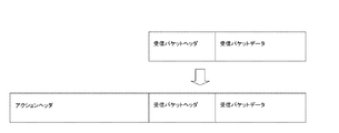
- the node of the communication system of the present invention has a function of specifying and executing a process to be executed by the own apparatus from an action sequence (process sequence) in an action header added to the received packet.
- the action header may be added to the node that first received the packet.
- the action sequence (processing sequence) in the action header may be acquired by inquiring an external control server or the like, or an action sequence (processing sequence) stored in advance in the node may be embedded. Moreover, what is necessary is just to let the node used as the termination
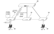
- FIG. 2 is a diagram showing a communication system according to the first embodiment of the present invention.
- three nodes 10, a control server 20, and a communication node 30 that communicates via the node 10 are shown.
- three nodes 10, the control server 20, and two communication nodes 30 are illustrated, but the number of each is merely an example, and any number can be used.
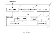
- FIG. 3 is a diagram showing a detailed configuration of the node 10.
- the node 10 includes a server communication unit 11 that communicates with the control server 30, a flow table management unit 12 that manages the flow table 13, and a transfer processing unit 14.
- the transfer processing unit 14 extracts an action to be executed by the own device from the action header added to the packet received as the user traffic, and outputs the action to the action execution unit 18.
- the action header is not added, the flow table 13 is searched, and the result is output to the action string setting unit 16, and the entry other than the own node of the entry searched by the table search unit 15
- An action sequence setting unit 16 that adds an action sequence to be executed at the node of the node to the received packet as an action header, and an action (action to be executed by the own device) output from the action extraction unit 17 is executed on the received packet.
- an action execution unit 18 inquires about an action sequence to be added to the control server 20 when there is no corresponding entry as a result of the search of the flow table 13 by the table search unit 15.
- the node 10 of the present invention can be realized by a configuration in which the action extraction unit 17 and the action sequence setting unit 16 are added to the OpenFlow switch.
- FIG. 4 is a diagram showing a detailed configuration of the control server 20.
- the control server 20 constructs network topology information based on the connection relationship between the flow entry database (flow entry DB) 21 storing the flow entry and the node 10 collected via the node communication unit 25.
- a topology management unit 22 a route / action calculation unit 23 for obtaining a packet transfer route and an action sequence to be executed by the node 10 on the transfer route based on network topology information constructed by the topology management unit 22, and a route A node that registers the result calculated by the action calculation unit 23 in the flow entry DB 21 as a flow entry and communicates with the flow entry management unit 24 responding to the flow entry addition or update request from the node 10 and the node 10 And a communication unit 25.
- flow entry database (flow entry DB) 21 can be omitted when there is no need to hold a flow entry instructed to be added or updated to the node 10.
- a configuration in which a flow entry database (flow entry DB) 21 is separately provided in an external server or the like can also be employed.
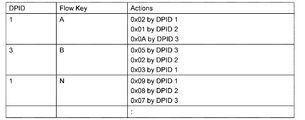
- FIG. 5 is an example of a flow entry stored in the flow entry DB 21.
- each entry includes a DPID (data path ID), a FlowKey (flow key; matching key), and an Actions (action sequence).
- DPID data path ID
- FlowKey flow key; matching key
- Actions action sequence
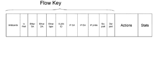
- FIG. 6 is a diagram showing a field configuration of FlowKey (matching key). For example, it is possible to cause the node 10 that has received a packet whose destination address (IP DA) is a specific server to execute an action defined in the Actions field (variable length). Similarly, for example, an action defined in the Actions field (variable length) can be executed for a packet input from a specific port (In Port).
- IP DA destination address
- IP DA destination address
- an action defined in the Actions field variable length
- an action defined in the Actions field can be executed for a packet input from a specific port (In Port).
- the control server 20 can also be realized by changing the configuration of the flow entry DB 21 of the OpenFlow controller or the contents of the flow entry instructing the node 10 to add or change.
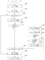
- FIG. 7 is a flowchart showing the operation of the node 10.
- the node 10 receives a packet from the communication node 30 or another node 10 (step S001)
- the node 10 extracts an action to be executed by the own device from the action header of the received packet (step S002).
- step S003 If the action is extracted as a result of the extraction of the action (No in step S003), the node 10 executes the action to be executed by the own device (step S009).
- the node 10 searches the flow table 13 for a flow entry that matches the received packet (step S103). S004).
- the node 10 extracts the action to be executed by itself (step S008) and finds it.
- the action sequence of the flow entry is added to the received packet header as an action header (step S009). For example, when a received packet is a subsequent packet of a packet already registered in the flow entry DB 21, extraction of an action to be executed by itself and an action using the search result from the flow table 13 as described above Header creation / addition is performed.
- step S005 if no flow entry matching the received packet is found as a result of searching the flow table 13 (No in step S005), the node 10 transmits the received packet or a part of the received packet to the control server 20.
- the creation of an action sequence is requested (step S006).
- the node 10 registers the received flow entry in the flow table 13 (step S007). Thereafter, the node 10 receives a packet output instruction from the control server 20 (step S011). When the packet output instruction is accompanied by a flow table search instruction (Yes in step S012), the node 10 searches again whether or not there is a flow entry that matches the packet (step S004-2), and is executed by itself. Extraction of an action to be performed (step S008) and processing for adding the obtained action sequence as an action header to the received packet header are performed (step S009).
- step S008 Extraction of an action to be executed (step S008) and processing for adding the obtained action sequence to the received packet header as an action header are performed (step S009).
- the node 10 executes an action to be executed by the own device (step S010).
- step S009 a method for adding an action sequence in step S009 will be described.
- an action header is added by adding (encapsulating) an action header to the head of the received packet.
- a method of embedding the action sequence in the header of the received packet can be adopted, which will be described as a third embodiment.
- each node 10 can specify an action to be executed.
- each node 10 can take a configuration in which actions are extracted in order from the top based on an appropriate delimiter, a separately provided Length field, or the like.
- FIG. 9B it is possible to adopt a configuration in which each node 10 executes an action while incrementing the leading pointer bit (adding only 1).
- the node # 2 transfers the packet from the port # 2 to the next hop node # 3
- the node # 3 transfers the packet from the port # 9 to the next hop. Will do.
- an action sequence in which the ID of each node and the action to be executed are paired can be used.
- the node # 2 having ID: B extracts “B2” with the ID: B of its own device in the action header, and moves from the port # 2 to the node # 3 of the next hop.
- the node # 3 having the ID: C transfers the packet, extracts “C9” with the ID: C of its own device in the action header, and transfers the packet from the port # 9 to the next hop.
- the action description order does not have to match the order of the nodes on the transfer route, and each node 10 specifies an action to be executed by the own device without rewriting the action header each time. It becomes possible to do.
- node # 2 which is determined to extract the action from bits 0-3 of the action header, extracts “2” and forwards the packet from port # 2 to node # 3 of the next hop. Then, the node # 3 that is determined to extract the action from bits 4-9 of the action header extracts “9” and transfers the packet from the port # 9 to the next hop. Even in the case of such an action sequence, the order of actions does not have to match the order of nodes on the transfer route, and each node 10 specifies an action to be executed on its own device without rewriting the action header each time. It becomes possible to do.
- FIG. 10 is a flowchart showing the operation of the control server 20.
- the control server 20 receives an action sequence creation request from the node 10 (step S101), as in step S006 of FIG. 7, the network management information constructed by the topology management unit 22 is received. Obtaining and calculating the packet transfer path (step S102).
- the control server 20 does not calculate the route except when the route cannot be created or the node on the route cannot be transferred (No in step S103).
- An action corresponding to the transfer path is calculated (step S104), and an action sequence is generated (step S105). For example, when the path of the node 10 of DPID # 2 and the node 10 of DPID # 3 is obtained from the node 10 of DPID # 1, “Output to Port # 9 by DPID 1 / Output to Port # 6 by DPID 2 / Output to Port # 1 by DPID 3 "is generated.
- control server 20 when the generation of the action sequence is completed, the control server 20 generates a FlowKey (matching key) for determining matching of the subsequent packet, and sets the calculated action sequence in the received packet.
- a flow entry in which two pieces of information including an action to be executed by the node that has received the received packet is defined is generated (step S106).
- the control server 20 transmits a flow entry to the request source node 10 of the action sequence (step S107), and if the node 10 does not buffer the packet (No in step S108), instructs the packet output instruction. This is performed (step S109).
- This packet output instruction indicates a packet to be output (received packet) and an action to be performed on the packet (adding an action header and output processing from a specified port), or a packet to be output (Received packet) and flow table search are instructed.
- packet transmission is omitted as will be described later with reference to FIGS.
- FIG. 11 is a sequence diagram showing a flow until a new flow entry is registered based on a packet (received packet) sent from the communication node A and the packet (received packet) is transferred to the next hop. is there.
- the node 10 determines that the action header is not added to the received packet, the node 10 searches the flow table 13 for whether or not the flow entry has already been created (same as step S004 in FIG. 7). . At this point, since the corresponding entry is not registered in the flow table 13, the node 10 requests the control server 20 to create an action sequence (same as step S006 in FIG. 7).
- the control server 20 that has received the action sequence creation request calculates the transfer path and action sequence of the received packet as described above, and sets the calculated action sequence in the received packet and the reception thereof.
- a flow entry having two pieces of information including an action to be executed by the node that has received the packet is generated (same as steps S102 to S106 in FIG. 10).
- the node 10 that has received the flow entry registers the flow entry in the flow table 13 (same as step S007 in FIG. 7).
- the node 10 when receiving a packet output instruction from the control server 20, the node 10 extracts an action to be executed by itself (same as step S008 in FIG. 7), and further adds an action header to the received packet (see FIG. 7 is the same as step S009 of FIG. 7), and is output from the designated port (same as step S010 of FIG. 7).
- FIG. 12 is a modification of the operation sequence of FIG. 11 differs from the operation sequence of FIG. 11 in that the control server 20 instructs the packet output to be output (received packet) and the search of the flow table as an action in the packet output instruction in step S109 of FIG. 10 after transmitting the flow entry. It is a point to do.
- the node 10 Upon receiving the instruction, the node 10 executes the flow table search again using the received packet as a key (step S004-2 in FIG. 12). Since the flow entry is registered in the previous step S007, the flow entry corresponding to the received packet is searched. The node 10 extracts an action to be executed by itself from the flow entry (same as step S008 in FIG. 7), adds an action header (same as step S009 in FIG. 7) to the received packet, and starts from the designated port. (Same as step S010 in FIG. 7).
- the flowchart of FIG. 7 is replaced with the flowchart of FIG. 13, and the operation sequence of FIG. 11 is replaced with the sequence of FIG.
- the difference between the flowchart of FIG. 7 and the operation sequence of FIG. 11 and the flowchart of FIG. 13 and the operation sequence of FIG. 14 is that a packet storage process (step S021) and a packet extraction process (step S022) are added.
- the packet output instruction from 20 is omitted.
- the buffer ID storing the received packet is attached to the action sequence creation request from the node 10 to the control server 20, and when the flow entry is transmitted from the control server 20 to the node 10,
- the node 10 extracts the received packet from the designated buffer ID (step S022) after registering the flow entry (step S007), and extracts the action to be executed by itself and the action header. Addition is performed (steps S008 to S009) and output from the designated port (step S010).
- the series of operations described so far are organized and described.
- the communication node A sends a packet having a header X to the communication node B ((1) in FIG. 15)
- the node # 1 that has received the packet searches its own flow table, but the corresponding entry is Therefore, the control server 20 is requested to generate an action sequence corresponding to the packet ((2) Packet-In in FIG. 15).
- the control server 20 generates a flow entry in which an action sequence (Acts) corresponding to the packet transmitted from the node # 1 and an appropriate matching key (X) is set, and returns it to the node # 1 ((4 in FIG. 15). ) FlowMod (Add)).
- FIG. 16 shows a state where the node # 1 registers the flow entry in the flow table.
- the control server 20 issues a packet output instruction to the node # 1 ((5) Packet-Out in FIG. 16)
- the node # 1 adds an action header (Acts) to the received packet and adds the node # 1. 2 ((6) of FIG. 16).
- Node # 2 reads the action to be executed by itself contained in the action header (Acts) and outputs the received packet from port # 5. The packet output from node # 2 is input to node # 3.
- Node # 3 reads out the action to be executed by itself contained in the action header (Acts), deletes the action header (Acts), and outputs the received packet from port # 9.
- the packet output from the node # 3 is input to the communication node B ((7) in FIG. 16).
- the node # 1 that has received the packet makes an inquiry to the control server 20. Instead, it searches the flow table of its own device, generates an action header from the action sequence of the corresponding entry, and transmits it to the node # 2 ((9) in FIG. 17). Thereafter, the packets are transferred in the order of the node # 2 and the node # 3, and finally reach the communication node B ((10) in FIG. 17).
- this operation is referred to as “breathing processing”.
- an intermediate node is requested to generate an action sequence ((1) Packet-In in FIG. 18), an action sequence to be executed by the subsequent node is acquired, and an action header is obtained. Can be added.
- the control server 20 can obtain a node that requires the breathing process when calculating a route and an action sequence.
- the breathing process can be realized not only when the necessity arises but also by transmitting a flow entry to the corresponding node in advance.
- control server 20 when the control server 20 receives an action sequence generation request ((1) Packet-In in FIG. 19), not only the node # 1 ((2) FlowMod in FIG. 19).
- the flow entry can also be transmitted to the node # n ⁇ 1 ((3) FlowMod in FIG. 19).
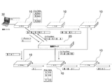
- FIG. 20 is a diagram showing a communication system according to the second embodiment of the present invention.
- each node 10a includes an action table, and an action can be specified by indicating a pointer of the action table.
- FIG. 21 is an example of a flow entry stored in the flow entry DB of the control server 20a according to the second embodiment of this invention.
- each entry includes a DPID (data path ID), a flow key (flow key; matching key), a node on which an action is to be executed, and a pointer to the action table.
- the size of the action header or the number of actions accommodated in the action header can be increased.
- FIG. 24 is a diagram showing a frame format when an action sequence is stored in a part of the MAC DA field of the received packet.
- 46 bits excluding the 7th and 8th bits (or the lower 2 bits of the 1st octet) from the beginning of the MAC DA field are used as the storage area for the action sequence.
- the maximum number of output ports of each node is 64, the port can be uniquely specified with 6 bits. Therefore, as shown in FIG. 9A, a maximum of seven actions can be accommodated if only the ports are arranged.
- FIG. 9C when adding the ID of each node, for example, if the length of the ID of each node is 8 bits, it is possible to accommodate a maximum of three actions.
- the MAC DA field is used, but the MAC SA field and other fields may be used. Furthermore, the MAC DA field and the MAC SA field may be used in succession. In this case, the number of actions that can be accommodated increases.
- the control server 20b generates a flow entry in which an action for replacing the matching key (X) and the header of the packet transmitted from the node # 1 with an action sequence header (X ′) is set, and returns it to the node # 1 (see FIG. 25 (4) FlowMod (Add)).
- the control server 20b generates a flow entry in which an action to be output to a predetermined port after restoring the action sequence header (X ′) to the original header (X) is generated, and the node # that becomes the final hop of the route 3 ((5) FlowMod (Add) in FIG. 25).
- control server 20b instructs the node # 1 to output a packet having a header with an action sequence header (X ′) ((6) Packet-Out in FIG. 25), the node # 1 The received packet is transferred to the node # 2 ((7) in FIG. 25).
- Node # 2 reads the action to be executed by itself contained in the action sequence header (X ') and outputs the received packet from port # 5. The packet output from node # 2 is input to node # 3.
- the node # 3 takes out the flow entry corresponding to the header with action sequence (X ′), restores the header with action sequence (X ′) to the original header (X), and then performs the restoration from the port # 9. Packet is output. The packet output from node # 3 is input to communication node B.
- the node # 1 that has received the packet makes an inquiry to the control server 20b. Instead, it searches the flow table of its own device, and transmits a packet with an action sequence header (X ′) added to node # 2 according to the contents of the corresponding entry ((10) in FIG. 25). Thereafter, the packets are transferred in the order of the node # 2 and the node # 3, and finally reach the communication node B ((11) in FIG. 25).
- this embodiment and the second embodiment can be combined.
- a pointer indicating an action on the action table of each node if a pointer indicating an action on the action table of each node is used, one header is used. It becomes possible to accommodate more actions.
- an action for returning the header (X ′) to the header (X) is stored in the action table of the node # 3, and a pointer (00x5) indicating the action is stored in the node # 3.
- a pointer (00x5) indicating the action is stored in the node # 3.
- the header restoration process can be realized by various methods. For example, as shown in FIG. 27, a flow entry for executing the next action can be added to the flow table of node # 3 of the last hop.
- IP DA Internet Protocol Destination Address
- ARP Address Resolution Protocol
- MAC DA corresponding to IP DA To get.
- (16) After restoring the header using the acquired MAC DA, (16) send the packet to the MAC DA receiving port.
- the contents of the MAC DA field (00: 00: 00: 00: 00: 01) are stored in the MAC SA field as shown in FIG.
- an action sequence is stored in the MAC DA field after evacuation, and the action is performed by writing back the MAC DA field to the final hop node # 3 using the contents of the MAC SA field.
- an address (00: 00: 00: 00: 00: 02) is entered in the MAC SA field, but this value may be an appropriate value.
- the accommodation destination of the action sequence is not limited to the example in FIG. 24, and other fields such as a MAC SA field, VAN_ID (VID), and Type can also be used.
- VAN_ID VAN_ID
- Type can also be used.
- the control servers 20 and 20a to 20f of the above-described embodiment can be realized as dedicated servers.
- the nodes 10, 10a to 10f include, in addition to the OpenFlow switch, a router in the IP network, MPLS (Multi-Protocol). It can be realized by an MPLS switch in a Label Switching network.
- the present invention can be applied to any network where the server centrally manages nodes in the network.
- the action sequence setting unit 16 that sets the action sequence and the entry node (for example, node # 1 in FIG. 18) that is the starting point of the route and the node that performs the breathing process ( For example, it may be at node # n-1) in FIG. Therefore, when it is known which node in the network corresponds to the entry node and the node that performs the breathing process, the action sequence setting unit 16 can be omitted.
- a flow table of a node that does not require at least an intermediate breathing process becomes unnecessary, and the number of entries can be reduced even in a node that requires a flow table. Therefore, the present invention can be suitably applied to a commercial network such as a data center.
Landscapes
- Engineering & Computer Science (AREA)
- Computer Networks & Wireless Communication (AREA)
- Signal Processing (AREA)
- Data Exchanges In Wide-Area Networks (AREA)
Abstract
Description
11 サーバ通信部
12 フローテーブル管理部
13 フローテーブル
14 転送処理部
15 テーブル検索部
16 アクション列設定部
17 アクション抽出部
18 アクション実行部
20、20a~20f 制御サーバ
21 フローエントリデータベース(フローエントリDB)
22 トポロジ管理部
23 経路・アクション計算部
24 フローエントリ管理部
25 ノード通信部
30 通信ノード
続いて、本発明の第1の実施形態について図面を参照して詳細に説明する。図2は、本発明の第1の実施形態に係る通信システムを示す図である。図2を参照すると、3つのノード10と、制御サーバ20と、ノード10を経由して通信する通信ノード30が示されている。なお、図2の例では、3つのノード10と、制御サーバ20と、2つの通信ノード30を示しているが、それぞれの数は、あくまで例示であり、それぞれ任意の数とすることができる。
続いて、本発明の第2の実施形態について図面を参照して詳細に説明する。図20は、本発明の第2の実施形態に係る通信システムを示す図である。図2に示した第1の実施形態との相違点は、各ノード10aが、アクションテーブルを備えており、アクションテーブルのポインタを指示することによりアクションを特定できるようになっている点である。
続いて、本発明の第3の実施形態について図面を参照して詳細に説明する。上記第1、第2の実施形態では、アクションヘッダは受信パケットの先頭に追加する形で付加するものとして説明したが(図8参照)、図23に示すように、受信パケットのヘッダの一部を書き換える態様を採ることも可能である。
Claims (33)
- データ転送ネットワークのノードが実行すべき処理を並べて構成された処理列を含むパケットを受信し、前記処理列に従って自装置が実行すべき処理を実行するノードを含むことを特徴とする通信システム。
- 前記処理列は、複数のノードが実行すべき処理で構成可能である請求項1の通信システム。
- 前記パケットは、前記処理に必要なデータをさらに含む請求項1または2の通信システム。
- 更に、入力パケットに前記処理列を含める処理列設定部を備えるノードを含む請求項1から3いずれか一の通信システム。
- 前記処理列設定部は、入力パケットに前記処理列が含まれていない場合、前記入力パケットのヘッダに含まれる情報に基づいて処理列を取得し、該処理列を前記入力パケットに含める請求項4の通信システム。
- 前記処理列設定部は、自装置が実行すべき処理が前記入力パケットの前記処理列に含まれていない場合、前記入力パケットのヘッダに含まれる情報に基づいて処理列を取得し、該処理列を前記入力パケットに含める請求項4の通信システム。
- さらに、前記入力パケットのヘッダに含まれる情報に基づいて処理列を作成し、前記処理列設定部を備えた所定のノードに送信する制御サーバを含む請求項4から6いずれか一の通信システム。
- 前記処理列設定部は、入力パケットに前記処理列が含まれておらず、かつ、当該パケットのヘッダ情報から対応する処理列を取得することができない場合に、前記制御サーバに対して前記入力パケットまたは入力パケットの一部を送信し前記処理列の送信を要求する請求項7の通信システム。
- 前記制御サーバは、前記処理列の送信を要求したノードに、入力パケットの所定領域の内容を、前記処理列に置き換えさせ、前記入力パケットから求めた最終ホップのノードに前記処理列に置き換えられた前記入力パケットの所定領域の内容を復元させる処理列を作成する請求項8の通信システム。
- 前記制御サーバは、前記処理列の長さが所定のサイズに収まるよう、前記処理列の送信を要求したノード以外の1以上のノードに、前記処理列の送信を要求する処理を実行させる請求項7から9いずれか一の通信システム。
- 前記個々のノードは、さらに、処理内容を登録した処理テーブルを備え、
前記処理列は、前記処理テーブルに登録された処理内容を特定するポインタによって記述されている請求項1から10いずれか一の通信システム。 - 前記ノードが、前記処理列に含まれる1つ以上の処理を実行した後、前記入力パケットに含まれる処理列を更新する機能を持つ請求項1から11いずれか一の通信システム。
- 前記処理列内の処理は、処理を実行するノードの順番で並べられており、前記処理列に従って、パケットが前記個々のノードに転送されていく請求項1から12いずれか一の通信システム。
- 前記処理列内の処理は、当該処理を実行するノードと対応付けて記述されており、前記個々のノードが、前記処理列から自装置に対応付けられた処理を抽出して実行する請求項1から12いずれか一の通信システム。
- データ転送ネットワークに配置され、
前記データ転送ネットワークのノードが実行すべき処理を並べて構成された処理列を含むパケットを受信し、前記処理列に従って自装置が実行すべき処理を実行するノード。 - 前記処理列は、複数のノードが実行すべき処理で構成可能である請求項15のノード。
- 前記パケットは、前記処理に必要なデータをさらに含む請求項15または16のノード。
- 更に、入力パケットに、前記処理列を含める処理列設定部を備える請求項15から17いずれか一のノード。
- 前記処理列設定部は、入力パケットに前記処理列が含まれていない場合、前記入力パケットのヘッダに含まれる情報に基づいて処理列を取得し、該処理列を前記入力パケットに含める請求項18のノード。
- 前記処理列設定部は、自装置が実行すべき処理が前記入力パケットの前記処理列に含まれていない場合、前記入力パケットのヘッダに含まれる情報に基づいて処理列を取得し、該処理列を前記入力パケットに含める請求項19のノード。
- 前記処理列設定部は、入力パケットに前記処理列が含まれておらず、かつ、当該パケットのヘッダ情報から対応する処理列を取得することができない場合に、前記処理列を送信する制御サーバに対して前記入力パケットまたは入力パケットの一部を送信し前記処理列の送信を要求する請求項20のノード。
- さらに、処理内容を登録した処理テーブルを備え、
前記処理テーブルに登録された処理内容を特定するポインタによって記述されている処理列から、前記ポインタを読み出して当該ポインタに対応する処理内容を実行する請求項15から21いずれか一のノード。 - 前記処理列に含まれる1つ以上の処理を実行した後、前記入力パケットに含まれる処理列を更新する機能を持つ請求項15から22いずれか一のノード。
- データ転送ネットワークに配置されたノードから受信した入力パケットに含まれる情報に基づいて、データ転送ネットワークのノードが実行すべき処理を並べた処理列を作成し、前記入力パケットを送信したノードに、前記処理列を送信する制御サーバ。
- 前記処理列は、複数のノードが実行すべき処理で構成されている請求項24の制御サーバ。
- 前記パケットは、前記処理に必要なデータをさらに含む請求項24または25の制御サーバ。
- 前記処理列を送信したノードに、入力パケットの所定領域の内容を、前記処理列に置き換えさせ、前記入力パケットから求めた最終ホップのノードに前記処理列に置き換えられた前記入力パケットの所定領域の内容を復元させる処理列を作成する請求項24から26いずれか一の制御サーバ。
- 前記処理列の長さが所定のサイズに収まるよう、前記処理列の送信したノード以外の1以上のノードに、前記処理列の送信を要求する処理を実行させる請求項24から27いずれか一の制御サーバ。
- 処理を実行するノードの順番で並べられており、前記処理列に従って、パケットが前記個々のノードに転送されていくよう処理列を作成する請求項24から28いずれか一の制御サーバ。
- 処理を実行するノードと処理と対応付けて記述されており、前記処理列から前記個々のノードが自装置に対応付けられた処理を抽出して実行できる処理列を作成する請求項24から28いずれか一の制御サーバ。
- 入力パケットに、データ転送ネットワークのノードが実行すべき処理を並べて構成された処理列を含めるステップと、
前記データ転送ネットワークのノードが、前記入力パケットに含まれた処理列に従って自装置が実行すべき処理を実行することを特徴とする通信方法。 - データ転送ネットワークに配置されたノードを構成するコンピュータに実行させるプログラムであって、
前記データ転送ネットワークのノードが実行すべき処理を並べて構成された処理列を含むパケットを受信し、前記処理列に従って自装置が実行すべき処理を抽出する処理を実行させ、さらに、
前記抽出した処理を実行させるプログラム。 - データ転送ネットワークに配置されたノードからの要求に応じて処理列を作成する制御サーバを構成するコンピュータに実行させるプログラムであって、
前記ノードから受信した入力パケットのヘッダに含まれる情報に基づいて、データ転送ネットワークのノードが実行すべき処理を並べた処理列を作成する処理と、
前記作成した処理列を前記ノードに送信する処理と、を実行させるプログラム。
Priority Applications (12)
| Application Number | Priority Date | Filing Date | Title |
|---|---|---|---|
| EP13183976.3A EP2731305B1 (en) | 2009-09-14 | 2009-09-14 | Communication system, node, control server and communication method |
| KR1020137023282A KR101408109B1 (ko) | 2009-09-14 | 2009-09-14 | 통신 시스템, 노드, 제어 장치, 및 제어 방법 |
| PCT/JP2009/066026 WO2011030462A1 (ja) | 2009-09-14 | 2009-09-14 | 通信システム、ノード、制御サーバ、通信方法およびプログラム |
| BR112012005704-9A BR112012005704A2 (pt) | 2009-09-14 | 2009-09-14 | sistema de comunicação, nó arranjado em uma rede para encaminhar dados, servidor de controle criar matriz de operações de processamento, método de comunicação, dispositivo de armazenamento legível por máquina, programa para criar matriz de operações de processamento |
| KR1020127007016A KR101365667B1 (ko) | 2009-09-14 | 2009-09-14 | 통신 시스템, 노드, 제어 서버, 통신 방법 및 프로그램 |
| EP09849239.0A EP2479937B1 (en) | 2009-09-14 | 2009-09-14 | Node, control server, communication method and program for packet processing using openflow |
| EP13183971.4A EP2696541A1 (en) | 2009-09-14 | 2009-09-14 | Communication system, node, control server, communication method and program |
| CN2009801614281A CN102498693A (zh) | 2009-09-14 | 2009-09-14 | 通信系统、节点、控制服务器、通信方法及程序 |
| KR1020137023279A KR101408108B1 (ko) | 2009-09-14 | 2009-09-14 | 통신 시스템, 노드, 제어 장치, 및 제어 방법 |
| JP2011530717A JP5626214B2 (ja) | 2009-09-14 | 2009-09-14 | 通信システム、ノード、制御サーバ、通信方法およびプログラム |
| US13/176,628 US8509252B2 (en) | 2009-09-14 | 2011-07-05 | Communication system, node, control server, communication method and program |
| US13/939,431 US9258220B2 (en) | 2009-09-14 | 2013-07-11 | Communication system, node, control server, communication method and program |
Applications Claiming Priority (1)
| Application Number | Priority Date | Filing Date | Title |
|---|---|---|---|
| PCT/JP2009/066026 WO2011030462A1 (ja) | 2009-09-14 | 2009-09-14 | 通信システム、ノード、制御サーバ、通信方法およびプログラム |
Related Child Applications (1)
| Application Number | Title | Priority Date | Filing Date |
|---|---|---|---|
| US13/176,628 Continuation US8509252B2 (en) | 2009-09-14 | 2011-07-05 | Communication system, node, control server, communication method and program |
Publications (1)
| Publication Number | Publication Date |
|---|---|
| WO2011030462A1 true WO2011030462A1 (ja) | 2011-03-17 |
Family
ID=43732146
Family Applications (1)
| Application Number | Title | Priority Date | Filing Date |
|---|---|---|---|
| PCT/JP2009/066026 Ceased WO2011030462A1 (ja) | 2009-09-14 | 2009-09-14 | 通信システム、ノード、制御サーバ、通信方法およびプログラム |
Country Status (7)
| Country | Link |
|---|---|
| US (2) | US8509252B2 (ja) |
| EP (3) | EP2731305B1 (ja) |
| JP (1) | JP5626214B2 (ja) |
| KR (3) | KR101408109B1 (ja) |
| CN (1) | CN102498693A (ja) |
| BR (1) | BR112012005704A2 (ja) |
| WO (1) | WO2011030462A1 (ja) |
Cited By (7)
| Publication number | Priority date | Publication date | Assignee | Title |
|---|---|---|---|---|
| WO2011148925A1 (ja) * | 2010-05-24 | 2011-12-01 | 日本電気株式会社 | 半導体装置とネットワークルーティング方法とシステム |
| WO2012127894A1 (ja) * | 2011-03-18 | 2012-09-27 | 日本電気株式会社 | ネットワークシステム、及びスイッチ方法 |
| WO2013078685A1 (zh) * | 2011-12-02 | 2013-06-06 | 华为技术有限公司 | 发送消息的方法、接收消息方法、开放流控制器及第一开放流交换机 |
| JP2014053758A (ja) * | 2012-09-07 | 2014-03-20 | Nippon Telegr & Teleph Corp <Ntt> | ネットワーク制御装置およびネットワーク制御方法 |
| JP2015508967A (ja) * | 2012-02-23 | 2015-03-23 | ビッグ スウィッチ ネットワークス インコーポレイテッド | コントローラでネットワークパケット転送を管理するシステム及び方法 |
| WO2015166979A1 (ja) * | 2014-05-01 | 2015-11-05 | 日本電気株式会社 | 通信装置、制御装置、通信システム、受信パケットの処理方法、通信装置の制御方法及びプログラム |
| WO2019044035A1 (ja) * | 2017-08-31 | 2019-03-07 | 株式会社Nttドコモ | 通信システム及び制御方法 |
Families Citing this family (16)
| Publication number | Priority date | Publication date | Assignee | Title |
|---|---|---|---|---|
| WO2012106869A1 (zh) * | 2011-07-06 | 2012-08-16 | 华为技术有限公司 | 一种报文处理方法及相关设备 |
| US9705918B2 (en) * | 2012-05-22 | 2017-07-11 | Sri International | Security mediation for dynamically programmable network |
| US9363152B2 (en) | 2012-06-11 | 2016-06-07 | Microsoft Technology Licensing, Llc | Large-scale passive network monitoring using multiple tiers of ordinary network switches |
| CN103703726B (zh) * | 2012-06-29 | 2017-04-26 | 华为技术有限公司 | 数据报文的控制方法、设备及系统 |
| CN107483345B (zh) * | 2012-07-11 | 2020-09-11 | 华为技术有限公司 | 业务处理方法、设备及系统 |
| US9813288B2 (en) | 2012-09-13 | 2017-11-07 | Nec Corporation | Control apparatus, control method, communication system, and program for issuing database operation command to operate database |
| US9071529B2 (en) * | 2012-10-08 | 2015-06-30 | Telefonaktiebolaget L M Ericsson (Publ) | Method and apparatus for accelerating forwarding in software-defined networks |
| FI20126105A7 (fi) * | 2012-10-25 | 2014-04-26 | Tellabs Oy | Menetelmä ja ohjauslaite ohjelmallisesti määriteltävän verkon konfiguroimiseksi |
| US9172550B2 (en) * | 2013-07-19 | 2015-10-27 | Globalfoundries U.S. 2 Llc Company | Management of a multicast system in a software-defined network |
| CN104579722A (zh) * | 2013-10-11 | 2015-04-29 | 中兴通讯股份有限公司 | 流统计能力的协商方法及装置 |
| FI20145041L (fi) * | 2014-01-17 | 2015-07-18 | Tellabs Oy | Verkkoelementti ja kontrolleri verkkoelementin hallitsemiseksi |
| CN105099913B (zh) | 2014-04-21 | 2018-07-20 | 新华三技术有限公司 | 一种报文转发方法及设备 |
| US9553762B1 (en) * | 2014-06-26 | 2017-01-24 | Altera Corporation | Network-on-chip with fixed and configurable functions |
| CA2963580C (en) | 2014-12-17 | 2020-04-21 | Huawei Technologies Co., Ltd. | Data forwarding method, device, and system in software-defined networking |
| US12526617B2 (en) | 2021-12-08 | 2026-01-13 | Palo Alto Networks, Inc. | Targeted PDU capture by a network device for roaming detection in wireless networks |
| KR102495450B1 (ko) * | 2022-06-10 | 2023-02-06 | 요다정보기술(주) | 클라우드 환경에서의 파일공유 시스템 |
Citations (6)
| Publication number | Priority date | Publication date | Assignee | Title |
|---|---|---|---|---|
| JP2002044126A (ja) * | 2000-07-21 | 2002-02-08 | Nec Corp | パケット転送方法および装置 |
| JP2003023463A (ja) * | 2001-06-18 | 2003-01-24 | Alcatel | 仮想回線でアクティブメッセージを送信する方法 |
| JP2004289794A (ja) * | 2002-12-02 | 2004-10-14 | Alcatel | データフローを選択してデグラデーションさせるための通信ネットワークにアクセスするための装置 |
| JP2006513671A (ja) | 2003-01-10 | 2006-04-20 | アルカテル | 制御されるアクティブネットワークにおけるシグナリング |
| JP2007053789A (ja) * | 2003-02-03 | 2007-03-01 | Nippon Telegr & Teleph Corp <Ntt> | エッジルータ装置、コアルータ装置、及びネットワークシステム |
| JP2008236652A (ja) | 2007-03-23 | 2008-10-02 | Nec Corp | 光通信システムおよびノード装置およびサービスクラス設定方法 |
Family Cites Families (24)
| Publication number | Priority date | Publication date | Assignee | Title |
|---|---|---|---|---|
| AU1199888A (en) * | 1987-03-13 | 1988-09-15 | Northern Telecom Limited | Communications system and components and methods for use therein |
| US5353283A (en) * | 1993-05-28 | 1994-10-04 | Bell Communications Research, Inc. | General internet method for routing packets in a communications network |
| JP2570963B2 (ja) | 1993-05-31 | 1997-01-16 | 日本電気株式会社 | パケット網における中継経路情報を用いたシグナリング方式 |
| JPH08251232A (ja) | 1995-03-15 | 1996-09-27 | Toshiba Corp | 通信・情報処理制御システム |
| JP3721784B2 (ja) * | 1998-05-27 | 2005-11-30 | 富士電機機器制御株式会社 | ネットワークシステム、送信装置、中継装置、および、記録媒体 |
| DE69935779T2 (de) | 1999-05-07 | 2007-12-27 | Alcatel Lucent | Verfahren, Apparat und Quell-Netzwerkknoten mit Apparat für eine explizit/implizit Leitweglenkung |
| JP3499791B2 (ja) | 2000-01-07 | 2004-02-23 | 日本電信電話株式会社 | パケットルーチング方法及びパケットルーチング装置 |
| JP3848067B2 (ja) | 2000-08-25 | 2006-11-22 | 株式会社エヌ・ティ・ティ・ドコモ | ネットワークにおけるルート設定方法、ルート管理方法及びアクティブルータ |
| US20030026268A1 (en) * | 2000-11-28 | 2003-02-06 | Siemens Technology-To-Business Center, Llc | Characteristic routing |
| US6990086B1 (en) * | 2001-01-26 | 2006-01-24 | Cisco Technology, Inc. | Method and system for label edge routing in a wireless network |
| US20020101868A1 (en) | 2001-01-30 | 2002-08-01 | David Clear | Vlan tunneling protocol |
| JP2002368787A (ja) | 2001-06-12 | 2002-12-20 | Fujitsu Ltd | 明示的経路指定中継装置 |
| DE60131551T2 (de) * | 2001-12-12 | 2008-10-23 | Alcatel Lucent | Telekommunikationsnetzwerk und entsprechenden Paketkopf |
| US7007142B2 (en) * | 2002-02-19 | 2006-02-28 | Intel Corporation | Network data storage-related operations |
| US8108554B1 (en) * | 2002-05-16 | 2012-01-31 | F5 Networks, Inc. | Method and system for automatically mapping secure network address translations |
| CN101505275A (zh) * | 2002-09-20 | 2009-08-12 | 松下电器产业株式会社 | 连接多个数据通信网络的中间网络元件 |
| JP2004153318A (ja) | 2002-10-28 | 2004-05-27 | Ntt Docomo Inc | パケット通信方法、パケット通信システム、送信元ノード、中継ノード及び中継器 |
| US20080008202A1 (en) * | 2002-10-31 | 2008-01-10 | Terrell William C | Router with routing processors and methods for virtualization |
| WO2004071034A1 (ja) | 2003-02-03 | 2004-08-19 | Nippon Telegraph And Telephone Corporation | データ転送装置およびデータ転送システム |
| JP4238086B2 (ja) | 2003-08-06 | 2009-03-11 | 株式会社エヌ・ティ・ティ・ドコモ | パケット転送制御方法、経路制御装置、フロー処理制御装置、端末管理装置、転送装置、処理サーバ装置、端末装置及びパケット転送システム |
| ATE496474T1 (de) * | 2006-05-02 | 2011-02-15 | Research In Motion Ltd | Mehrschichtiges envelope-verfahren und system zur inhaltslieferung |
| CN100469052C (zh) * | 2006-08-04 | 2009-03-11 | 北京方正奥德计算机系统有限公司 | 一种数据路由分配方法 |
| JP5182146B2 (ja) * | 2009-02-23 | 2013-04-10 | 富士通株式会社 | 経路決定プログラム、管理装置及びネットワーク・システム |
| WO2011144495A1 (en) * | 2010-05-19 | 2011-11-24 | Telefonaktiebolaget L M Ericsson (Publ) | Methods and apparatus for use in an openflow network |
-
2009
- 2009-09-14 KR KR1020137023282A patent/KR101408109B1/ko not_active Expired - Fee Related
- 2009-09-14 EP EP13183976.3A patent/EP2731305B1/en active Active
- 2009-09-14 WO PCT/JP2009/066026 patent/WO2011030462A1/ja not_active Ceased
- 2009-09-14 BR BR112012005704-9A patent/BR112012005704A2/pt not_active Application Discontinuation
- 2009-09-14 KR KR1020127007016A patent/KR101365667B1/ko not_active Expired - Fee Related
- 2009-09-14 EP EP13183971.4A patent/EP2696541A1/en not_active Withdrawn
- 2009-09-14 CN CN2009801614281A patent/CN102498693A/zh active Pending
- 2009-09-14 JP JP2011530717A patent/JP5626214B2/ja active Active
- 2009-09-14 EP EP09849239.0A patent/EP2479937B1/en active Active
- 2009-09-14 KR KR1020137023279A patent/KR101408108B1/ko not_active Expired - Fee Related
-
2011
- 2011-07-05 US US13/176,628 patent/US8509252B2/en not_active Expired - Fee Related
-
2013
- 2013-07-11 US US13/939,431 patent/US9258220B2/en active Active
Patent Citations (6)
| Publication number | Priority date | Publication date | Assignee | Title |
|---|---|---|---|---|
| JP2002044126A (ja) * | 2000-07-21 | 2002-02-08 | Nec Corp | パケット転送方法および装置 |
| JP2003023463A (ja) * | 2001-06-18 | 2003-01-24 | Alcatel | 仮想回線でアクティブメッセージを送信する方法 |
| JP2004289794A (ja) * | 2002-12-02 | 2004-10-14 | Alcatel | データフローを選択してデグラデーションさせるための通信ネットワークにアクセスするための装置 |
| JP2006513671A (ja) | 2003-01-10 | 2006-04-20 | アルカテル | 制御されるアクティブネットワークにおけるシグナリング |
| JP2007053789A (ja) * | 2003-02-03 | 2007-03-01 | Nippon Telegr & Teleph Corp <Ntt> | エッジルータ装置、コアルータ装置、及びネットワークシステム |
| JP2008236652A (ja) | 2007-03-23 | 2008-10-02 | Nec Corp | 光通信システムおよびノード装置およびサービスクラス設定方法 |
Non-Patent Citations (4)
| Title |
|---|
| DAVID L. TENNENHOUSE ET AL.: "A Survey of Active Network Research", IEEE COMMUNICATIONS MAGAZINE, vol. 35, no. 1, January 1997 (1997-01-01), pages 80 - 86 |
| NICK MCKEOWN ET AL., OPENFLOW ENABLING INNOVATION IN CAMPUS NETWORKS, 27 August 2009 (2009-08-27), Retrieved from the Internet <URL:http://.openflowswitch.org/ldocuments/openflow-wp-latest.pdf> |
| OPENFLOW SWITCH SPECIFICATION, 27 August 2009 (2009-08-27), Retrieved from the Internet <URL:http://www.openflowswitch.org/documents/openflow-spec- v0.9.0.pdf> |
| See also references of EP2479937A4 |
Cited By (14)
| Publication number | Priority date | Publication date | Assignee | Title |
|---|---|---|---|---|
| WO2011148925A1 (ja) * | 2010-05-24 | 2011-12-01 | 日本電気株式会社 | 半導体装置とネットワークルーティング方法とシステム |
| US9391895B2 (en) | 2011-03-18 | 2016-07-12 | Nec Corporation | Network system and switching method thereof |
| WO2012127894A1 (ja) * | 2011-03-18 | 2012-09-27 | 日本電気株式会社 | ネットワークシステム、及びスイッチ方法 |
| JP5660198B2 (ja) * | 2011-03-18 | 2015-01-28 | 日本電気株式会社 | ネットワークシステム、及びスイッチ方法 |
| WO2013078685A1 (zh) * | 2011-12-02 | 2013-06-06 | 华为技术有限公司 | 发送消息的方法、接收消息方法、开放流控制器及第一开放流交换机 |
| US9641421B2 (en) | 2011-12-02 | 2017-05-02 | Huawei Technologies Co., Ltd. | Message transmitting method, message receiving method, openflow controller and first openflow switch |
| JP2015508967A (ja) * | 2012-02-23 | 2015-03-23 | ビッグ スウィッチ ネットワークス インコーポレイテッド | コントローラでネットワークパケット転送を管理するシステム及び方法 |
| JP2014053758A (ja) * | 2012-09-07 | 2014-03-20 | Nippon Telegr & Teleph Corp <Ntt> | ネットワーク制御装置およびネットワーク制御方法 |
| JPWO2015166979A1 (ja) * | 2014-05-01 | 2017-04-20 | 日本電気株式会社 | 通信装置、制御装置、通信システム、受信パケットの処理方法、通信装置の制御方法及びプログラム |
| WO2015166979A1 (ja) * | 2014-05-01 | 2015-11-05 | 日本電気株式会社 | 通信装置、制御装置、通信システム、受信パケットの処理方法、通信装置の制御方法及びプログラム |
| RU2656706C1 (ru) * | 2014-05-01 | 2018-06-06 | Нек Корпорейшн | Устройство связи, устройство управления, система связи, способ обработки принимаемого пакета, способ управления устройством связи и программа |
| US10686712B2 (en) | 2014-05-01 | 2020-06-16 | Nec Corporation | Communication apparatus, control apparatus, communication system, received packet processing method, communication apparatus control method, and program |
| WO2019044035A1 (ja) * | 2017-08-31 | 2019-03-07 | 株式会社Nttドコモ | 通信システム及び制御方法 |
| JPWO2019044035A1 (ja) * | 2017-08-31 | 2020-08-13 | 株式会社Nttドコモ | 通信システム及び制御方法 |
Also Published As
| Publication number | Publication date |
|---|---|
| EP2731305B1 (en) | 2021-01-13 |
| KR20130109245A (ko) | 2013-10-07 |
| KR101365667B1 (ko) | 2014-02-21 |
| CN102498693A (zh) | 2012-06-13 |
| EP2731305A1 (en) | 2014-05-14 |
| US20130308650A1 (en) | 2013-11-21 |
| EP2479937A1 (en) | 2012-07-25 |
| JP5626214B2 (ja) | 2014-11-19 |
| EP2696541A1 (en) | 2014-02-12 |
| US8509252B2 (en) | 2013-08-13 |
| KR20130109246A (ko) | 2013-10-07 |
| KR101408109B1 (ko) | 2014-06-17 |
| EP2731305A3 (en) | 2014-07-09 |
| EP2479937A4 (en) | 2013-12-18 |
| JPWO2011030462A1 (ja) | 2013-02-04 |
| US20120008629A1 (en) | 2012-01-12 |
| US9258220B2 (en) | 2016-02-09 |
| EP2479937B1 (en) | 2020-10-21 |
| KR20120062793A (ko) | 2012-06-14 |
| KR101408108B1 (ko) | 2014-06-17 |
| BR112012005704A2 (pt) | 2020-08-25 |
Similar Documents
| Publication | Publication Date | Title |
|---|---|---|
| JP5626214B2 (ja) | 通信システム、ノード、制御サーバ、通信方法およびプログラム | |
| CN102577271B (zh) | 信息系统、控制服务器、虚拟网络管理方法以及程序 | |
| CN104272679B (zh) | 通信系统、控制装置、通信方法以及记录介质 | |
| CN105245449B (zh) | 通信系统、控制装置、处理规则设置方法、分组传输方法 | |
| JP5644895B2 (ja) | 通信システム、制御装置、通信方法及びプログラム | |
| JP5440691B2 (ja) | パケット転送システム、制御装置、転送装置、処理規則の作成方法およびプログラム | |
| JP5888338B2 (ja) | 通信システムおよび通信方法 | |
| WO2011118586A1 (ja) | 通信システム、制御装置、転送ノード、処理規則の更新方法およびプログラム | |
| JP5637289B2 (ja) | 通信システム、ノード、制御サーバ、通信方法およびプログラム | |
| JP5573909B2 (ja) | 通信システム、ノード、制御装置、通信方法およびプログラム | |
| JP6036940B2 (ja) | 通信システム、ノード、制御装置、通信方法およびプログラム | |
| JP5794355B2 (ja) | 通信システム、ノード、制御装置、通信方法およびプログラム | |
| HK1174161A (en) | Communication system, node, control server, communication method and program | |
| HK1171131A (en) | Information system, control server, virtual network management method, and program |
Legal Events
| Date | Code | Title | Description |
|---|---|---|---|
| WWE | Wipo information: entry into national phase |
Ref document number: 200980161428.1 Country of ref document: CN |
|
| 121 | Ep: the epo has been informed by wipo that ep was designated in this application |
Ref document number: 09849239 Country of ref document: EP Kind code of ref document: A1 |
|
| WWE | Wipo information: entry into national phase |
Ref document number: 2011530717 Country of ref document: JP |
|
| NENP | Non-entry into the national phase |
Ref country code: DE |
|
| ENP | Entry into the national phase |
Ref document number: 20127007016 Country of ref document: KR Kind code of ref document: A |
|
| WWE | Wipo information: entry into national phase |
Ref document number: 2009849239 Country of ref document: EP |
|
| WWE | Wipo information: entry into national phase |
Ref document number: 3222/CHENP/2012 Country of ref document: IN |
|
| REG | Reference to national code |
Ref country code: BR Ref legal event code: B01A Ref document number: 112012005704 Country of ref document: BR |
|
| ENP | Entry into the national phase |
Ref document number: 112012005704 Country of ref document: BR Kind code of ref document: A2 Effective date: 20120314 |