WO2011030719A1 - 高速応答性を実現するロケットエンジンシステム - Google Patents
高速応答性を実現するロケットエンジンシステム Download PDFInfo
- Publication number
- WO2011030719A1 WO2011030719A1 PCT/JP2010/065124 JP2010065124W WO2011030719A1 WO 2011030719 A1 WO2011030719 A1 WO 2011030719A1 JP 2010065124 W JP2010065124 W JP 2010065124W WO 2011030719 A1 WO2011030719 A1 WO 2011030719A1
- Authority
- WO
- WIPO (PCT)
- Prior art keywords
- turbine
- pump
- turbo pump
- fuel
- flow rate
- Prior art date
- Legal status (The legal status is an assumption and is not a legal conclusion. Google has not performed a legal analysis and makes no representation as to the accuracy of the status listed.)
- Ceased
Links
Images


Classifications
-
- F—MECHANICAL ENGINEERING; LIGHTING; HEATING; WEAPONS; BLASTING
- F02—COMBUSTION ENGINES; HOT-GAS OR COMBUSTION-PRODUCT ENGINE PLANTS
- F02K—JET-PROPULSION PLANTS
- F02K9/00—Rocket-engine plants, i.e. plants carrying both fuel and oxidant therefor; Control thereof
- F02K9/42—Rocket-engine plants, i.e. plants carrying both fuel and oxidant therefor; Control thereof using liquid or gaseous propellants
- F02K9/44—Feeding propellants
- F02K9/46—Feeding propellants using pumps
-
- F—MECHANICAL ENGINEERING; LIGHTING; HEATING; WEAPONS; BLASTING
- F04—POSITIVE - DISPLACEMENT MACHINES FOR LIQUIDS; PUMPS FOR LIQUIDS OR ELASTIC FLUIDS
- F04D—NON-POSITIVE-DISPLACEMENT PUMPS
- F04D13/00—Pumping installations or systems
- F04D13/02—Units comprising pumps and their driving means
- F04D13/028—Units comprising pumps and their driving means the driving means being a planetary gear
-
- F—MECHANICAL ENGINEERING; LIGHTING; HEATING; WEAPONS; BLASTING
- F04—POSITIVE - DISPLACEMENT MACHINES FOR LIQUIDS; PUMPS FOR LIQUIDS OR ELASTIC FLUIDS
- F04D—NON-POSITIVE-DISPLACEMENT PUMPS
- F04D13/00—Pumping installations or systems
- F04D13/02—Units comprising pumps and their driving means
- F04D13/04—Units comprising pumps and their driving means the pump being fluid driven
-
- F—MECHANICAL ENGINEERING; LIGHTING; HEATING; WEAPONS; BLASTING
- F05—INDEXING SCHEMES RELATING TO ENGINES OR PUMPS IN VARIOUS SUBCLASSES OF CLASSES F01-F04
- F05D—INDEXING SCHEME FOR ASPECTS RELATING TO NON-POSITIVE-DISPLACEMENT MACHINES OR ENGINES, GAS-TURBINES OR JET-PROPULSION PLANTS
- F05D2270/00—Control
- F05D2270/01—Purpose of the control system
- F05D2270/02—Purpose of the control system to control rotational speed (n)
- F05D2270/024—Purpose of the control system to control rotational speed (n) to keep rotational speed constant
Definitions
- the present invention relates to a turbo pump and a rocket engine system that realize high-speed response.
- This application claims priority based on Japanese Patent Application No. 2009-207480 for which it applied to Japan on September 8, 2009, and uses the content here.
- Such a turbo pump rocket engine is also attracting attention as a rocket engine for vertical take-off and landing aircraft.
- This vertical take-off and landing aircraft is designed on the assumption that it will fly with a profile as shown in FIG. 8A, for example. That is, as shown in FIG. 8A, Ph1: Vertical rise, Ph2: Pitch maneuver, Ph3: MECO (Main Engine Cut-Off), Ph4: Wide range (hovering), Ph5: Re-entry / lift flight, Ph6: Approach guidance , Ph7: engine re-ignition, Ph8: landing guidance, Ph9: vertical landing.
- Ph4 in addition to the wide range (hovering), for example, ballistic flight or round flight may be performed.
- the rocket engine mounted on the vertical take-off and landing aircraft has controllability against crosswinds during landing and thrust slots corresponding to the aircraft weight that is less than half when landing compared to launching.
- high-speed response response frequency of 1 Hz or more
- wide-range thrust variable capability are required during the operation of the rocket engine, especially in the range of Ph1 to 2 and Ph7 to 9 in Fig. 8A, especially during landing In the range of Ph7-9.
- Conventional rocket engines are designed for one-way operation up to space, and are generally operated at maximum thrust during launch to minimize gravity loss, and thereafter, such as aircraft acceleration and aerodynamic loads. Due to the constraints, the thrust is only slightly reduced semi-statically. That is, the conventional rocket engine is designed with the characteristics in a substantially steady state as an evaluation object, and the thrust response is generally not taken into consideration. This is no exception even for a turbo pump rocket engine.
- FIG. 8B shows a combustion test result of a conventional turbo pump rocket engine.
- the horizontal axis of FIG. 8B is time (sec), and the vertical axis is the combustion pressure Pc (kg / cm 2 ), the rotational speed Nf (rpm) of the fuel turbo pump, and the rotational speed No (rpm) of the oxidant turbo pump. .
- the combustion pressure Pc corresponding to the engine thrust is reduced from about 30 (kg / cm 2 ) to about 20 (kg / cm 2 ), that is, until it changes to 66% thrust. It can be seen that it takes about 5 seconds.
- the response time of 5 seconds is 0.2 (Hz) in terms of response frequency, and it is impossible to satisfy the high speed response required for the rocket engine of the vertical take-off and landing aircraft described above. Delicate maneuvers are difficult. It can be seen from FIG. 8B that the rotational speeds Nf and No of each turbo pump also change in conjunction with the change in thrust (change in combustion pressure Pc).
- the conventional turbo pump rocket engine cannot satisfy the high-speed response required for the rocket engine of the vertical take-off and landing aircraft, and it is difficult to use it for take-off and landing as it is.
- FIG. 8B since the time required to change from the rotational speed corresponding to the current thrust to the new rotational speed appears as a thrust response delay, the inertia moment of the turbo pump rotary shaft However, this is considered to be a factor that deteriorates the response of the conventional turbo pump rocket engine.
- the moment of inertia of the turbo pump should be reduced.
- the detailed calculation method is omitted, assuming that most of the inertial moment of the turbo pump depends on the disk part corresponding to the pump impeller and the turbine disk, the diameter of these disk parts is the current value under the condition of constant material density. By setting the value to about half of the value, the moment of inertia can be reduced to 1/10 (that is, the response can be improved by about 10 times).
- turbo pumps used in rocket engines mounted on aerospace vehicles such as vertical take-off and landing aircraft operate near the upper limit of the mechanical rotation speed allowed for bearings and seals, so they are more than double the current level. It is not easy to drive at a rotational speed of.
- the increase in the rotational speed causes an increase in centrifugal force beyond the effect of reducing the moment of inertia, it is necessary to change the material of the disk part or increase the thickness in order to maintain durability. This leads to an increase in weight, and it is difficult to reduce the moment of inertia as calculated.
- the present invention has been made in view of the above-described circumstances, and an object thereof is to provide a turbo pump and a rocket engine capable of realizing a high-speed response without depending on the moment of inertia of the rotating shaft.
- a turbo pump according to the present invention is a turbo pump in which a pump impeller is coupled to one end of a rotating shaft and a turbine is coupled to the other end, and the rotational speed of the rotating shaft is independent of the pump flow rate.
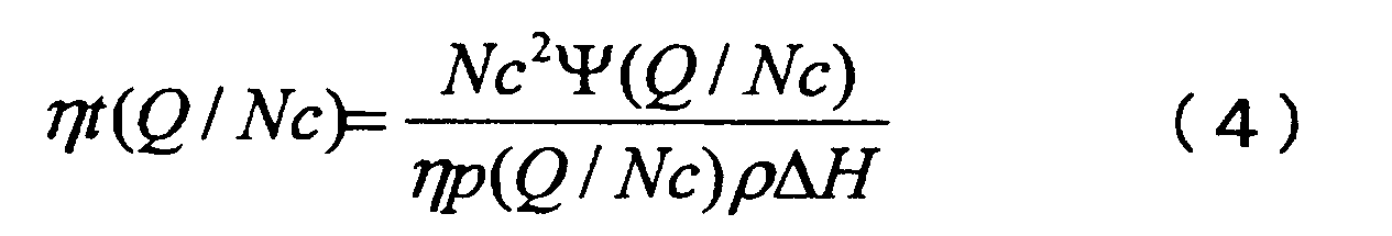
- the conditional expression includes the following equation (4) consisting of turbine efficiency ⁇ t, pump efficiency ⁇ p, lift coefficient ⁇ , pump flow rate Q, rotation speed Nc, turbine enthalpy drop ⁇ H, and turbine inlet fuel density ⁇ . It is represented by
- the rocket engine according to the present invention is a rocket engine including a fuel turbo pump and an oxidant turbo pump. At least for the fuel turbo pump, the rotational speed of the rotating shaft is kept constant regardless of the pump flow rate.
- the entire system including the fuel turbo pump was designed so that the equivalent region between the turbine efficiency curve obtained based on the conditional expression and the turbine efficiency curve of the actual machine becomes the operation region.
- the conditional expression includes the turbine efficiency ⁇ t, the pump efficiency ⁇ p, the lift coefficient ⁇ , the pump flow rate Q, the rotational speed Nc, the turbine enthalpy drop ⁇ H, and the turbine inlet fuel density ⁇ , the above expression (4) It is represented by
- the fuel sent from the fuel turbo pump is supplied to a regenerative cooling heat exchanger provided in a combustor via a fuel side thrust control valve provided downstream of the fuel turbo pump. After flowing in and gasified, it becomes gas fuel and is used to drive the turbine of the fuel turbo pump and the oxidant turbo pump, and then supplied to the combustor and sent from the oxidant turbo pump. Is supplied to the combustor via an oxidant side thrust control valve provided downstream of the oxidant turbo pump.
- turbo pump since the turbo pump can be operated in an operation region in which the rotation speed of the rotary shaft is kept constant without depending on the pump flow rate, a high-speed response can be realized without depending on the inertia moment of the rotary shaft.
- Turbo pumps and rocket engines can be provided.
- Turbine efficiency curve ⁇ 1 t (turbine efficiency curve required for high-speed response) obtained based on a conditional expression that keeps the rotational speed of the rotating shaft constant without depending on the pump flow rate, and the turbine efficiency curve of the actual machine it is a diagram showing the eta 2 t (turbine efficiency curve feasible). This is a case where the turbine efficiency curve ⁇ 1 t required for high-speed response is different. This is a case where the turbine efficiency curve ⁇ 1 t required for high-speed response is different.
- the responsiveness is represented by a Bode diagram. It is a measurement result of a turbine operation area. This is a flight profile of a vertical take-off and landing aircraft. It is a combustion test result of the conventional turbo pump type rocket engine.
- FIG. 1 is a schematic configuration diagram of a rocket engine 1 in the present embodiment.
- the rocket engine 1 in this embodiment includes a fuel turbo pump 11, an oxidant turbo pump 12, a fuel side thrust control valve 13, a fuel side main valve 14, a bypass orifice 15, and an oxidant side thrust control.
- the valve 16, the oxidant side main valve 17, and the combustor 18 are roughly configured.
- the fuel turbo pump 11 is a centrifugal turbo pump in which a pump impeller 11b is coupled to one end side of a rotating shaft 11a rotatably supported in a main body casing, and a turbine 11c is coupled to the other end side.
- the liquid hydrogen supplied from the fuel tank is pumped to the combustor 18.
- the oxidant turbo pump 12 is a centrifugal turbo pump in which a pump impeller 12b is coupled to one end of a rotating shaft 12a rotatably supported in a main body casing, and a turbine 12c is coupled to the other end.
- Liquid oxygen (LOX) supplied from the illustrated oxidant tank is pumped to the combustor 18.
- the liquid hydrogen supplied to the fuel turbo pump 11 is boosted by the rotational operation of the pump impeller 11b driven by the turbine 11c, and then sent to the fuel-side thrust control valve 13 installed on the downstream side of the fuel turbo pump 11.
- the fuel-side thrust control valve 13 is an electronic control valve whose opening is adjusted in accordance with a control signal input from a control device (not shown). That is, the liquid hydrogen delivered from the fuel turbo pump 11 is adjusted in flow rate by the fuel-side thrust control valve 13 and then delivered to the fuel-side main valve 14 installed on the downstream side.
- the fuel-side main valve 14 is an electronic control valve similar to the fuel-side thrust control valve 13, but is adjusted to a fully open state when the engine is operating and to a fully closed state when the engine is stopped. That is, during engine operation, the liquid hydrogen whose flow rate is adjusted by the fuel-side thrust control valve 13 passes through the fuel-side main valve 14 while maintaining the flow rate, and is installed on the nozzle wall surface and combustion chamber wall surface of the combustor 18. It flows into the regenerative cooling heat exchanger 18a and is used for regenerative cooling of the combustor 18.
- the liquid hydrogen used for regenerative cooling of the combustor 18 is heated and gasified while passing through the regenerative cooling heat exchanger 18a, and becomes high-temperature and high-pressure gaseous hydrogen (GH 2 ), thereby regenerating cooling heat. It flows into the turbine inlet of the fuel turbo pump 11 from the exchanger 18a and is used to drive the turbine 11c.
- the gaseous hydrogen flowing out from the turbine outlet of the fuel turbo pump 11 flows into the turbine inlet of the oxidant turbo pump 12 and is used for rotationally driving the turbine 12c, and then sent out from the turbine outlet to the combustor 18.
- a part of the gaseous hydrogen flowing out from the turbine outlet of the fuel turbo pump 11 is sent to the combustor 18 through the bypass orifice 15.
- the bypass orifice 15 is used to adjust the flow rate of gaseous hydrogen flowing into the combustor 18.
- the liquid oxygen supplied to the oxidant turbo pump 12 is boosted by the rotational operation of the pump impeller 12b driven by the turbine 12c, and then the oxidant side thrust control installed on the downstream side of the oxidant turbo pump 12. It is delivered to the valve 16.
- the oxidant side thrust control valve 16 is an electronic control valve similar to the fuel side thrust control valve 13. That is, the liquid oxygen sent from the oxidant turbo pump 12 is adjusted in flow rate by the oxidant side thrust control valve 16 and then sent to the oxidant side main valve 17 installed on the downstream side.
- the oxidant-side main valve 17 is an electronic control valve that is adjusted to a fully open state when the engine is operating and to a fully closed state when the engine is stopped, like the fuel side main valve 14. That is, during engine operation, the liquid oxygen whose flow rate is adjusted by the oxidant-side thrust control valve 16 passes through the oxidant-side main valve 17 while maintaining the flow rate, and is sent directly to the combustor 18.
- the combustor 18 mixes and burns the gaseous hydrogen and liquid oxygen supplied as described above in the combustion chamber, and injects a high-temperature high-pressure gas generated by the combustion from a nozzle installed in the lower portion, thereby thrust. Is generated.
- liquid hydrogen gas hydrogen supplied to the combustor 18 by adjusting the opening degrees of the fuel side thrust control valve 13 and the oxidant side thrust control valve 16 described above.
- the flow rate of liquid oxygen is controlled.
- the equivalent region means that the difference between the ideal turbine efficiency (turbine efficiency required for high-speed response) and the turbine efficiency that can actually be manufactured (realizable turbine efficiency) is 5% or less. More preferably, it is 3% or less.
- the reason why it is set to 5% or less is that when it is larger than 5%, the fluctuation of the turbo pump rotational speed becomes remarkable, and the constant rotational speed condition intended by the present invention is not satisfied.
- the factor that makes the responsiveness of the turbo pump rocket engine worse is the moment of inertia of the rotating shaft of the turbo pump.
- High-speed response is realized by a design change that reduces this moment of inertia. It is difficult. Therefore, the present inventor changes the viewpoint and thinks that the influence of the moment of inertia can be removed if the rotational speed is always constant without depending on the thrust, in other words, without depending on the pump flow rate. The following considerations were made.
- the rotational speed balance point N of the turbo pump is a point that satisfies the following formula (1) in which the turbine generated torque Tt and the pump consumption torque Tp are equal.
- Ixx is a moment of inertia.
- the turbine torque Tt is expressed by the following formula (2)
- the pump consumption torque Tp is expressed by the following formula (3).
- ⁇ is the head coefficient
- ⁇ p is the pump efficiency
- ⁇ t is the turbine efficiency
- Q is the pump flow rate
- mt black circle above m
- ⁇ H is the turbine enthalpy drop
- U is the turbine peripheral speed
- C0 is the turbine inflow speed
- Q / N is the pump flow coefficient
- U / C0 is the turbine speed ratio.
- the pump flow rate Q and the turbine flow rate mt are always equal.
- the turbine peripheral speed U can be expressed in association with the rotational speed N. Therefore, a conditional expression for maintaining the rotation speed N constant without depending on the pump flow rate Q (in other words, without depending on the generated thrust) is expressed by the following expression (4).
- ⁇ is the turbine inlet fuel density.
- the turbine efficiency function is the above in the corresponding Q / Nc range ( It is sufficient if the formula 4) is satisfied.
- the expression (4) means that turbo pump characteristics (turbine efficiency ⁇ t, pump efficiency ⁇ p, lift coefficient ⁇ ) and operating conditions (turbine) so that the equality is established even if the pump flow rate Q changes.
- the rotational speed Nc of the rotating shaft is always kept constant, and as a result, the thrust control response does not depend on the inertia moment Ixx of the turbo pump, and a high-speed response can be realized. It is that there is sex.
- the pump efficiency ⁇ p is defined by the ratio of the work power Wo used for boosting, which is the original purpose, from the work power Wi input from the outside through the rotating shaft, as shown in the following equation (7).
- the boosting power Wo is expressed by the following equation (8)
- the input power Wi is expressed by the following equation (9) when various losses Wl are taken into consideration.
- the pump efficiency ⁇ p is expressed by the following equation (10) from the above equations (7) to (9).
- the loss Wl can be described as a function of only Q / N. Although the mechanism of loss itself is not expressed in the cubic form, it is accepted here as a relatively good approximation.
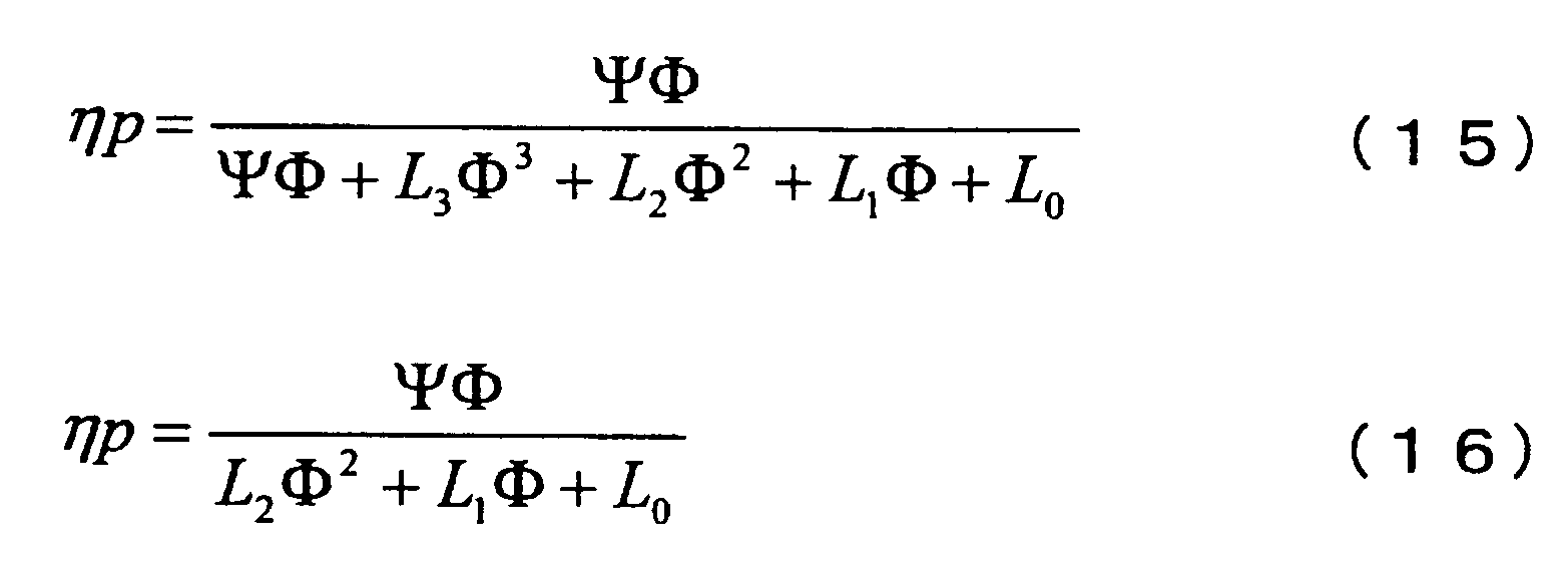
- the pump efficiency ⁇ p is expressed by the following expression (15).
- the coefficient is reassigned again with respect to the denominator of the equation (15)
- the general form of the pump efficiency ⁇ p is expressed as the following equation (16).
- Turbine efficiency ⁇ t is the recovery rate of enthalpy that the injected gas releases adiabatically.
- the adiabatic discharge power Wi between the turbine inlet and outlet is expressed by the following equation (17) when the gas inflow velocity C0 is used.
- the work rate Wt recovered by the turbine is expressed by the following equation (18) using relative speeds W1 and W2 with respect to the rotor.
- ⁇ 1 and ⁇ 2 are relative inflow / outflow angles to the rotor.
- the turbine efficiency ⁇ t is expressed by the following equation (19), and when the rotor internal speed coefficient ⁇ r and the nozzle blowing angle ⁇ are used to rewrite the relative speeds W1 and W2 with the rotor, the following equation (20) is obtained. It is done. This is a quadratic function that is convex upward through the origin.
- a combustor CC (combustion) passes through a turbine inlet (turbine inlet pressure Pt) from a fuel tank (tank pressure Ptnk) (not shown).
- turbine inlet pressure Pt turbine inlet pressure
- tank pressure Ptnk tank pressure
- ⁇ 3 is a constant
- Rt is the turbine radius
- Tt is the turbine inlet temperature.
- the turbine inlet temperature Tt is assumed to be raised only by the regenerative cooling heat exchanger, although loss at the turbo pump FTP and heat input from outside can be considered.
- the temperature rise ⁇ T obtained by the refrigerant when passing through the regenerative cooling heat exchanger is expressed as a function of the combustion pressure Pc, the mixing ratio MR, and the cooling flow rate Q, but now the mixing ratio MR is constant and the combustion pressure Pc is the flow rate Q. Therefore, the temperature rise ⁇ T is expressed by a function of only the flow rate Q as shown in (28) below.
- the turbine inlet temperature Tt can be similarly expressed as a function Tt (Q) of only the flow rate Q.
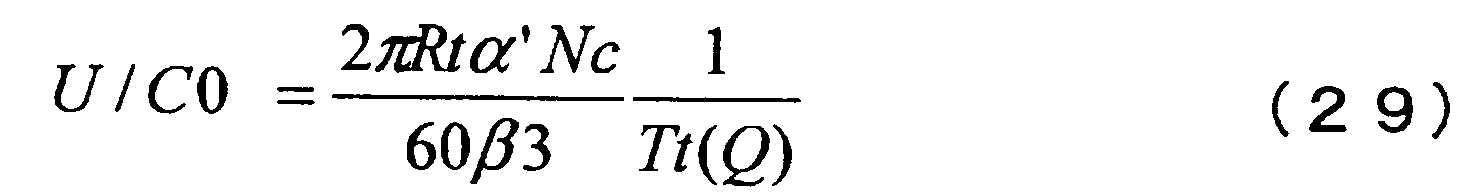
- the turbine speed ratio U / C0 expressed by the above equation (27) is expressed as the following equation (29) as a function of only the flow rate Q under the fixed rotation speed Nc. .
- the turbine efficiency ⁇ t of the turbo pump FTP that satisfies the condition that the rotational speed N is kept constant without depending on the pump flow rate Q is the characteristic vector (L 0 , L 1 , L 2 ) and the turbine operating condition ⁇ H / Nc 2 corresponding to the head in the case of the pump. That is, the turbine operating condition is determined by the turbine inlet fuel density ⁇ , the turbine enthalpy drop ⁇ H, and the rotational speed Nc.
- the ideal turbine efficiency function (actual turbine efficiency curve) based on the characteristics of the actual pump is generally an upward convex quadratic function.
- Turbine efficiency obtained based on the above equation (21) that is, the turbine efficiency curve of the actual machine
- the above equation (30) that is, the conditional equation that keeps the rotational speed of the rotating shaft constant without depending on the pump flow rate.
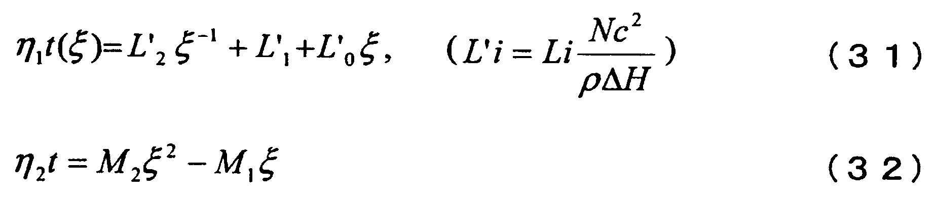
- the following equation (31) is a downwardly convex curve having an offset amount L ′ 1 and gradually approaching L ′ 0 ⁇ .
- FIG. 3 shows a two-dimensional coordinate system in which the horizontal axis is ⁇ and the vertical axis is the turbine efficiency ⁇ t, and the turbine efficiency curve ⁇ 1 t obtained from the above equation (31) (that is, the rotation of the rotating shaft without depending on the pump flow rate).
- Turbine efficiency curve obtained based on a conditional expression in which the number is kept constant) and a turbine efficiency curve ⁇ 2 t obtained from the above expression (32) (that is, a turbine efficiency curve of an actual machine) are plotted.
- the actual machine here refers to a general turbo pump whose maximum efficiency is about 0.4 to 0.8 and whose intersection with the horizontal axis can be adjusted to some extent by the angle of the turbine nozzle and the number of stages of the turbine. Point to.
- the turbine efficiency curve ⁇ 1 t required for high-speed response and the actual turbine efficiency curve ⁇ 2 t are essentially different in shape, so that even if the equivalent region A is selected well, an error is inevitable. Due to the error, some fluctuations in the rotational speed are involved, and the response as the engine system is expected to be slower than the ideal state, but it is considered that there is no problem in practical use.
- the turbine efficiency curve ⁇ 1 t required for high-speed response is given by the characteristics and operating conditions of the turbo pump.
- the two curves are greatly separated and there is no equivalent region, or as shown in FIG. 4B, the two curves intersect at two locations and there are two equivalent regions. Is also possible.
- the offset amount L′ 1 changes and balances when the rotational speed Nc decreases in an actual engine system.
- the rotational speed Nc increases and balances.
- the turbine enthalpy drop ⁇ H can be adjusted by increasing or decreasing the turbine nozzle equivalent area At, and as a result, the offset amount L ′ 1 can be adjusted.
- the turbine speed ratio U / C0 can be adjusted by increasing or decreasing the turbine nozzle equivalent area At.
- the turbine speed ratio U / C0 can be determined by the pipe resistance including the resistance Rtcv of the fuel side thrust control valve.
- the rotational speed Nc can be determined by a balance of pump characteristics, turbine characteristics, heat exchanger characteristics, and pipe resistance characteristics. At this time, in order to widen the adjustment allowance, the rotational speed Nc can be controlled by setting the turbine gas passage system to partial admission.
- FIG. 5 shows the combustion pressure Pc (thrust) and the rotational speed Nf of the fuel turbo pump 11 when the thrust command is gradually increased from 0.5 to 10 (Hz) in order to evaluate the response. This is a result of measuring a temporal change in the rotational speed No of the oxidant turbo pump 12.
- the broken line in a figure is a calculated value by simulation, and a continuous line is a measurement result.
- the combustion pressure Pc (thrust) shows a very high responsiveness while the rotational speed Nf of the fuel turbo pump 11 remains substantially constant. I understand that.
- FIG. 6 shows the response in a Bode diagram. Although there is a slight deviation from the linear first-order lag model, it can be said that a response of 6 (Hz) or higher is shown if it is evaluated at -3 (dB) point. Considering that the response of the conventional turbo pump rocket engine was 0.2 (Hz), this is a great improvement. Moreover, it turns out that the turbine operation area
- the expander cycle engine has been described as an example of the rocket engine 1.
- the present invention can be applied to any turbo pump rocket engine.
- the turbo pump according to the present invention can be used not only as a rocket engine but also as a turbocharger mounted on, for example, an automobile engine or a marine engine, and provides a high-speed response engine without a turbo lag. Can do.
- the turbo pump can be operated in an operation region in which the rotation speed of the rotary shaft is kept constant without depending on the pump flow rate, so that a high-speed response can be realized without depending on the moment of inertia of the rotary shaft.
- a turbo pump and a rocket engine can be provided.
Landscapes
- Engineering & Computer Science (AREA)
- Mechanical Engineering (AREA)
- General Engineering & Computer Science (AREA)
- Chemical & Material Sciences (AREA)
- Combustion & Propulsion (AREA)
- Structures Of Non-Positive Displacement Pumps (AREA)
- Control Of Turbines (AREA)
- Control Of Non-Positive-Displacement Pumps (AREA)
- Non-Positive Displacement Air Blowers (AREA)
Abstract
Description
本願は、2009年9月8日に日本国に出願された特願2009-207480号に基づき優先権を主張し、その内容をここに援用する。
また、上記のターボポンプにおいて、前記条件式は、タービン効率ηt、ポンプ効率ηp、揚程係数Ψ、ポンプ流量Q、回転数Nc、タービンエンタルピー落差ΔH及びタービン入口燃料密度ρからなる下記(4)式で表される。
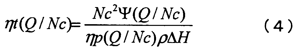
また、上記のロケットエンジンにおいて、前記条件式は、タービン効率ηt、ポンプ効率ηp、揚程係数Ψ、ポンプ流量Q、回転数Nc、タービンエンタルピー落差ΔH及びタービン入口燃料密度ρからなる上記(4)式で表される。
また、上記のロケットエンジンにおいて、前記燃料ターボポンプから送出された燃料は、前記燃料ターボポンプの下流側に設けられた燃料側推力制御弁を介して燃焼器に設けられた再生冷却熱交換器に流入してガス化された後、ガス燃料となって前記燃料ターボポンプ及び前記酸化剤ターボポンプのタービン駆動に使用された後に前記燃焼器に供給され、前記酸化剤ターボポンプから送出された酸化剤は、前記酸化剤ターボポンプの下流側に設けられた酸化剤側推力制御弁を介して前記燃焼器に供給される。
酸化剤ターボポンプ12は、本体ケーシング内において回転自在に支持された回転軸12aの一端側にポンプインペラ12bが結合され、他端側にタービン12cが結合されて成る遠心型ターボポンプであり、不図示の酸化剤タンクから供給される液体酸素(LOX)を燃焼器18に圧送するものである。
また、燃料ターボポンプ11のタービン出口から流出したガス水素の一部は、バイパスオリフィス15を介して燃焼器18に送出される。このバイパスオリフィス15は、燃焼器18に流入するガス水素の流量を調整するために用いられる。
酸化剤側メイン弁17は、燃料側メイン弁14と同じく、エンジン運転時には全開状態に、エンジン停止時には全閉状態に調節される電子制御弁である。つまり、エンジン運転時では、酸化剤側推力制御弁16によって流量調整された液体酸素は、その流量を維持したまま酸化剤側メイン弁17を通過し、直接燃焼器18に送出される。
このように構成された本実施形態におけるロケットエンジン1では、上記の燃料側推力制御弁13及び酸化剤側推力制御弁16の開度を調節して、燃焼器18に供給する液体水素(ガス水素)と液体酸素の流量を調整することにより推力制御を行う。
以下では、上記のように、ポンプ流量に依存せずに回転軸の回転数が一定に保たれる条件式に基づいて得られたタービン効率曲線と、実機のタービン効率曲線との等価領域を燃料ターボポンプ11のタービン運転領域とすることで、推力制御の高速応答を実現できる理由について説明する。
ここで、等価領域とは、理想的なタービン効率(高速応答に要求されるタービン効率)と実際に製造可能なタービン効率(実現可能なタービン効率)との差異が5%以下であることを意味しており、3%以下であることがさらに望ましい。5%以下としているのは、5%より大きいと、ターボポンプ回転数の変動が顕著になり、本発明が意図する回転数一定の条件が満たされなくなるためである。
ターボポンプの回転数バランス点Nは、タービン発生トルクTtとポンプ消費トルクTpが等しくなる下記(1)式を満たす点となる。なお、下記(1)式において、Ixxは慣性モーメントである。


上記の考察を基に、ターボポンプ特性値相互の関係をスロットリングに要求される広範囲に渡って安定化させる条件を検討すると以下のようになる。なお、ここでの検討の流れは、一般的なターボポンプの関数系を定め、それを基に単純な形式へと導いていくものとする。
(1)揚程係数Ψ
遠心型ターボポンプの昇圧ΔPは、回転数の二乗で表されるいわゆる入力揚程Hiから、構造的な内部流体抵抗Rによる圧損を差し引いたものであり、さらに吸い込み部分での最適な流入量Qs (ショックレス)からのずれを考慮して一般に下記(5)式で表される。なお、下記(5)式において、AN2は入力揚程(=Hi)、RQ2は内部圧力損失、K(Q-Qs)2は衝突損失である。


ポンプ効率ηpは回転軸を通して外部から入力された仕事率Wiの内、本来の目的である昇圧に使われた仕事率Woの比率で下記(7)式のように定義される。また、昇圧仕事率Woは下記(8)式で表され、入力された仕事率Wiは様々な損失Wlを考慮すれば下記(9)式で表される。


タービン効率ηtは、吹き込まれたガスが断熱的に放出するエンタルピーの回収率である。タービン入口-出口間の断熱放出仕事率Wiは、ガス流入速度C0を用いると下記(17)式で表される。また、タービンが回収した仕事率Wtは、ローターとの相対速度W1、W2を用いて下記(18)式で表される。なお、下記(18)式において、β1、β2はローターへの相対流入・流出角度である。


上述した考察結果に基づき、図2に示すようなロケットエンジンモデルを用いて、高速応答を満たす解が実在するかについての検討を実施した。このロケットエンジンモデルでは、ターボポンプFTPを燃料側のみ装着し、燃料をターボポンプFTPから燃料側推力制御弁TCVFを介して、燃焼器CCの再生冷却燃交換器、ターボポンプFTPのタービンを経由して燃焼器CCに供給するものとする。また、酸化剤は、燃料との混合比MRが常に一定となるように強制的に燃焼器CCに供給するものとする。推力制御は、ポンプ下流に直列に接続された燃料側推力制御弁TCVFの流体抵抗を変化させて、燃料の流量を調整することで行う。


ここで、ξ=Φ-1と置き、ξを用いて上記(30)式を変形すると下記(31)式が得られ、上記(21)式を変形すると下記(32)式が得られる。下記(31)式は、オフセット量L’1を有し、やがてL’0ξに漸近する下に凸の曲線である。
本願発明者は、以上のような考察に基づいて、ポンプ流量に依存せずに回転軸の回転数が一定に保たれる条件式(4)式に基づいて得られたタービン効率曲線と、実機のタービン効率曲線との等価領域Aが燃料ターボポンプ11のタービン運転領域となるように、燃料ターボポンプ11を含む系全体を設計したロケットエンジン1の実験機を製作し、応答性評価実験を行った。
11…燃料ターボポンプ
12…酸化剤ターボポンプ
13…燃料側推力制御弁
14…燃料側メイン弁
15…バイパスオリフィス
16…酸化剤側推力制御弁
17…酸化剤側メイン弁
18…燃焼器
Claims (5)
- 回転軸の一端にポンプインペラが、他端にタービンが結合されたターボポンプにおいて、
ポンプ流量に依存せずに前記回転軸の回転数が一定に保たれる条件式に基づいて得られたタービン効率曲線と、実機のタービン効率曲線との等価領域が運転領域となるよう設計されたターボポンプ。 - 前記条件式は、タービン効率ηt、ポンプ効率ηp、揚程係数Ψ、ポンプ流量Q、回転数Nc、タービンエンタルピー落差ΔH及びタービン入口燃料密度ρからなる下記(4)式で表される請求項1に記載のターボポンプ。
- 燃料ターボポンプと酸化剤ターボポンプとを備えるロケットエンジンにおいて、
少なくとも前記燃料ターボポンプについて、ポンプ流量に依存せずに回転軸の回転数が一定に保たれる条件式に基づいて得られたタービン効率曲線と、実機のタービン効率曲線との等価領域が運転領域となるように、前記燃料ターボポンプを含む系全体の設計がなされたロケットエンジン。 - 前記条件式は、タービン効率ηt、ポンプ効率ηp、揚程係数Ψ、ポンプ流量Q、回転数Nc、タービンエンタルピー落差ΔH及びタービン入口燃料密度ρからなる上記(4)式で表される請求項3に記載のロケットエンジン。
- 前記燃料ターボポンプから送出された燃料は、前記燃料ターボポンプの下流側に設けられた燃料側推力制御弁を介して燃焼器に設けられた再生冷却熱交換器に流入してガス化された後、ガス燃料となって前記燃料ターボポンプ及び前記酸化剤ターボポンプのタービン駆動に使用された後に前記燃焼器に供給され、
前記酸化剤ターボポンプから送出された酸化剤は、前記酸化剤ターボポンプの下流側に設けられた酸化剤側推力制御弁を介して前記燃焼器に供給される、
請求項3または4に記載のロケットエンジン。
Priority Applications (6)
| Application Number | Priority Date | Filing Date | Title |
|---|---|---|---|
| EP10815316.4A EP2476887B1 (en) | 2009-09-08 | 2010-09-03 | Rocket engine system for realizing high-speed response |
| JP2011530820A JP5582145B2 (ja) | 2009-09-08 | 2010-09-03 | 高速応答性を実現するロケットエンジンシステム |
| IN2226DEN2012 IN2012DN02226A (ja) | 2009-09-08 | 2010-09-03 | |
| RU2012113229/06A RU2531489C2 (ru) | 2009-09-08 | 2010-09-03 | Система ракетного двигателя для осуществления высокоскоростного реагирования |
| US13/394,843 US8943795B2 (en) | 2009-09-08 | 2010-09-03 | Rocket engine system for realizing high-speed response |
| CN201080039481.7A CN102648343B (zh) | 2009-09-08 | 2010-09-03 | 实现高速响应性的火箭发动机系统 |
Applications Claiming Priority (2)
| Application Number | Priority Date | Filing Date | Title |
|---|---|---|---|
| JP2009-207480 | 2009-09-08 | ||
| JP2009207480 | 2009-09-08 |
Publications (1)
| Publication Number | Publication Date |
|---|---|
| WO2011030719A1 true WO2011030719A1 (ja) | 2011-03-17 |
Family
ID=43732391
Family Applications (1)
| Application Number | Title | Priority Date | Filing Date |
|---|---|---|---|
| PCT/JP2010/065124 Ceased WO2011030719A1 (ja) | 2009-09-08 | 2010-09-03 | 高速応答性を実現するロケットエンジンシステム |
Country Status (7)
| Country | Link |
|---|---|
| US (1) | US8943795B2 (ja) |
| EP (1) | EP2476887B1 (ja) |
| JP (1) | JP5582145B2 (ja) |
| CN (1) | CN102648343B (ja) |
| IN (1) | IN2012DN02226A (ja) |
| RU (1) | RU2531489C2 (ja) |
| WO (1) | WO2011030719A1 (ja) |
Cited By (1)
| Publication number | Priority date | Publication date | Assignee | Title |
|---|---|---|---|---|
| US10605203B2 (en) | 2014-09-25 | 2020-03-31 | Patched Conics, LLC. | Device, system, and method for pressurizing and supplying fluid |
Families Citing this family (31)
| Publication number | Priority date | Publication date | Assignee | Title |
|---|---|---|---|---|
| US8671658B2 (en) | 2007-10-23 | 2014-03-18 | Ener-Core Power, Inc. | Oxidizing fuel |
| US8701413B2 (en) | 2008-12-08 | 2014-04-22 | Ener-Core Power, Inc. | Oxidizing fuel in multiple operating modes |
| US9279364B2 (en) | 2011-11-04 | 2016-03-08 | Ener-Core Power, Inc. | Multi-combustor turbine |
| US9273606B2 (en) | 2011-11-04 | 2016-03-01 | Ener-Core Power, Inc. | Controls for multi-combustor turbine |
| US9371993B2 (en) | 2012-03-09 | 2016-06-21 | Ener-Core Power, Inc. | Gradual oxidation below flameout temperature |
| US9328916B2 (en) | 2012-03-09 | 2016-05-03 | Ener-Core Power, Inc. | Gradual oxidation with heat control |
| US9234660B2 (en) | 2012-03-09 | 2016-01-12 | Ener-Core Power, Inc. | Gradual oxidation with heat transfer |
| US8980192B2 (en) | 2012-03-09 | 2015-03-17 | Ener-Core Power, Inc. | Gradual oxidation below flameout temperature |
| US9347664B2 (en) | 2012-03-09 | 2016-05-24 | Ener-Core Power, Inc. | Gradual oxidation with heat control |
| US9206980B2 (en) | 2012-03-09 | 2015-12-08 | Ener-Core Power, Inc. | Gradual oxidation and autoignition temperature controls |
| US9359947B2 (en) | 2012-03-09 | 2016-06-07 | Ener-Core Power, Inc. | Gradual oxidation with heat control |
| US9381484B2 (en) | 2012-03-09 | 2016-07-05 | Ener-Core Power, Inc. | Gradual oxidation with adiabatic temperature above flameout temperature |
| US9267432B2 (en) | 2012-03-09 | 2016-02-23 | Ener-Core Power, Inc. | Staged gradual oxidation |
| US8807989B2 (en) | 2012-03-09 | 2014-08-19 | Ener-Core Power, Inc. | Staged gradual oxidation |
| US9194584B2 (en) | 2012-03-09 | 2015-11-24 | Ener-Core Power, Inc. | Gradual oxidation with gradual oxidizer warmer |
| US9534780B2 (en) * | 2012-03-09 | 2017-01-03 | Ener-Core Power, Inc. | Hybrid gradual oxidation |
| US9359948B2 (en) | 2012-03-09 | 2016-06-07 | Ener-Core Power, Inc. | Gradual oxidation with heat control |
| US9273608B2 (en) | 2012-03-09 | 2016-03-01 | Ener-Core Power, Inc. | Gradual oxidation and autoignition temperature controls |
| US9726374B2 (en) * | 2012-03-09 | 2017-08-08 | Ener-Core Power, Inc. | Gradual oxidation with flue gas |
| US9017618B2 (en) | 2012-03-09 | 2015-04-28 | Ener-Core Power, Inc. | Gradual oxidation with heat exchange media |
| US8926917B2 (en) | 2012-03-09 | 2015-01-06 | Ener-Core Power, Inc. | Gradual oxidation with adiabatic temperature above flameout temperature |
| US9567903B2 (en) | 2012-03-09 | 2017-02-14 | Ener-Core Power, Inc. | Gradual oxidation with heat transfer |
| US9328660B2 (en) | 2012-03-09 | 2016-05-03 | Ener-Core Power, Inc. | Gradual oxidation and multiple flow paths |
| US9353946B2 (en) | 2012-03-09 | 2016-05-31 | Ener-Core Power, Inc. | Gradual oxidation with heat transfer |
| US8980193B2 (en) | 2012-03-09 | 2015-03-17 | Ener-Core Power, Inc. | Gradual oxidation and multiple flow paths |
| FR2991392B1 (fr) * | 2012-06-01 | 2016-01-15 | Snecma | Turbopompe |
| FR2992364B1 (fr) * | 2012-06-25 | 2014-07-25 | Snecma | Turbopompe |
| JP6539626B2 (ja) * | 2016-09-16 | 2019-07-03 | 日立建機株式会社 | 作業機械 |
| CN111412084B (zh) * | 2020-04-07 | 2024-08-30 | 北京航天动力研究所 | 一种多级泵级间分流的核热发动机系统 |
| CN112901353B (zh) * | 2021-02-01 | 2022-04-12 | 中国科学院力学研究所 | 一种碳氢燃料主动冷却超燃冲压发动机起动系统及方法 |
| CN119982258B (zh) * | 2024-12-27 | 2026-01-23 | 西安航天动力研究所 | 模拟整机点火状态的燃气发生器点火试验装置及其工况设计方法 |
Citations (7)
| Publication number | Priority date | Publication date | Assignee | Title |
|---|---|---|---|---|
| JPH10238408A (ja) * | 1997-02-21 | 1998-09-08 | Ishikawajima Harima Heavy Ind Co Ltd | エキスパンダサイクルエンジン |
| JPH11229963A (ja) | 1998-02-12 | 1999-08-24 | Ishikawajima Harima Heavy Ind Co Ltd | 液体ロケットエンジンにおけるエキスパンダサイクル構造 |
| JP2002538346A (ja) * | 1999-01-29 | 2002-11-12 | アストリウム・ゲゼルシャフト・ミット・ベシュレンクテル・ハフツング | ロケットブースタ用燃料供給装置、およびこの装置内で使用する熱交換器 |
| JP2003148250A (ja) * | 2001-11-14 | 2003-05-21 | Mitsubishi Heavy Ind Ltd | ロケットエンジン解析装置及びプログラム |
| JP2007016781A (ja) * | 2005-07-06 | 2007-01-25 | United Technol Corp <Utc> | 接触分解ガス発生装置サイクルにおいて気体炭化水素を利用したブースターロケットエンジン |
| JP2008267385A (ja) * | 2007-04-20 | 2008-11-06 | Pratt & Whitney Rocketdyne Inc | エキスパンダサイクルロケットエンジンおよびエキスパンダサイクルロケットエンジンを作動させる方法 |
| JP2009207480A (ja) | 2008-02-07 | 2009-09-17 | Kubota Corp | コンバイン |
Family Cites Families (12)
| Publication number | Priority date | Publication date | Assignee | Title |
|---|---|---|---|---|
| US3017745A (en) * | 1956-08-31 | 1962-01-23 | Napier & Son Ltd | Fuel supply systems for rocket engines |
| US3623329A (en) | 1960-04-12 | 1971-11-30 | United Aircraft Corp | Control system for liquid rocket |
| GB1020995A (en) * | 1962-09-04 | 1966-02-23 | Snecma | Centrifugal pump |
| US3224189A (en) * | 1963-05-31 | 1965-12-21 | Martin Marietta Corp | Liquid rocket propellant feed system |
| GB1008157A (en) * | 1963-08-16 | 1965-10-27 | Bristol Siddeley Engines Ltd | Improvements in or relating to rocket engines |
| FR2524938A1 (fr) * | 1982-04-08 | 1983-10-14 | Centre Nat Etd Spatiales | Procede de regulation du rapport de melange des propergols pour un moteur a propergols liquides par mesure des debits et regulateurs pour sa mise en oeuvre |
| RU2176744C2 (ru) * | 1999-08-06 | 2001-12-10 | Федеральное государственное унитарное предприятие Конструкторское бюро химавтоматики | Жидкостный ракетный двигатель |
| US6619031B1 (en) * | 2000-04-27 | 2003-09-16 | Vladimir V. Balepin | Multi-mode multi-propellant liquid rocket engine |
| RU2187684C2 (ru) * | 2000-10-03 | 2002-08-20 | Федеральное государственное унитарное предприятие "Исследовательский центр им. М.В.Келдыша" | Способ работы жидкостного ракетного двигателя и жидкостной ракетный двигатель |
| RU2232915C2 (ru) | 2002-03-14 | 2004-07-20 | ОАО "НПО Энергомаш им. акад. В.П. Глушко" | Жидкостный ракетный двигатель с дожиганием турбогаза |
| US6652224B2 (en) * | 2002-04-08 | 2003-11-25 | Holset Engineering Company Ltd. | Variable geometry turbine |
| JP4288051B2 (ja) * | 2002-08-30 | 2009-07-01 | 三菱重工業株式会社 | 斜流タービン、及び、斜流タービン動翼 |
-
2010
- 2010-09-03 JP JP2011530820A patent/JP5582145B2/ja active Active
- 2010-09-03 EP EP10815316.4A patent/EP2476887B1/en active Active
- 2010-09-03 US US13/394,843 patent/US8943795B2/en active Active
- 2010-09-03 CN CN201080039481.7A patent/CN102648343B/zh active Active
- 2010-09-03 RU RU2012113229/06A patent/RU2531489C2/ru active
- 2010-09-03 IN IN2226DEN2012 patent/IN2012DN02226A/en unknown
- 2010-09-03 WO PCT/JP2010/065124 patent/WO2011030719A1/ja not_active Ceased
Patent Citations (7)
| Publication number | Priority date | Publication date | Assignee | Title |
|---|---|---|---|---|
| JPH10238408A (ja) * | 1997-02-21 | 1998-09-08 | Ishikawajima Harima Heavy Ind Co Ltd | エキスパンダサイクルエンジン |
| JPH11229963A (ja) | 1998-02-12 | 1999-08-24 | Ishikawajima Harima Heavy Ind Co Ltd | 液体ロケットエンジンにおけるエキスパンダサイクル構造 |
| JP2002538346A (ja) * | 1999-01-29 | 2002-11-12 | アストリウム・ゲゼルシャフト・ミット・ベシュレンクテル・ハフツング | ロケットブースタ用燃料供給装置、およびこの装置内で使用する熱交換器 |
| JP2003148250A (ja) * | 2001-11-14 | 2003-05-21 | Mitsubishi Heavy Ind Ltd | ロケットエンジン解析装置及びプログラム |
| JP2007016781A (ja) * | 2005-07-06 | 2007-01-25 | United Technol Corp <Utc> | 接触分解ガス発生装置サイクルにおいて気体炭化水素を利用したブースターロケットエンジン |
| JP2008267385A (ja) * | 2007-04-20 | 2008-11-06 | Pratt & Whitney Rocketdyne Inc | エキスパンダサイクルロケットエンジンおよびエキスパンダサイクルロケットエンジンを作動させる方法 |
| JP2009207480A (ja) | 2008-02-07 | 2009-09-17 | Kubota Corp | コンバイン |
Non-Patent Citations (1)
| Title |
|---|
| See also references of EP2476887A4 |
Cited By (1)
| Publication number | Priority date | Publication date | Assignee | Title |
|---|---|---|---|---|
| US10605203B2 (en) | 2014-09-25 | 2020-03-31 | Patched Conics, LLC. | Device, system, and method for pressurizing and supplying fluid |
Also Published As
| Publication number | Publication date |
|---|---|
| IN2012DN02226A (ja) | 2015-08-21 |
| US20120167552A1 (en) | 2012-07-05 |
| US8943795B2 (en) | 2015-02-03 |
| JP5582145B2 (ja) | 2014-09-03 |
| EP2476887B1 (en) | 2016-10-26 |
| RU2012113229A (ru) | 2013-10-20 |
| CN102648343A (zh) | 2012-08-22 |
| EP2476887A1 (en) | 2012-07-18 |
| EP2476887A4 (en) | 2015-08-05 |
| CN102648343B (zh) | 2014-09-17 |
| JPWO2011030719A1 (ja) | 2013-02-07 |
| RU2531489C2 (ru) | 2014-10-20 |
Similar Documents
| Publication | Publication Date | Title |
|---|---|---|
| JP5582145B2 (ja) | 高速応答性を実現するロケットエンジンシステム | |
| JP5681721B2 (ja) | 適応コアエンジン | |
| CN111102098B (zh) | 基于前置式压缩导流叶轮的涡轮喷气推进系统、控制方法 | |
| US20180050812A1 (en) | Aircraft fuel pump systems | |
| CN105339630A (zh) | 带有推力控制的发动机超速保护 | |
| JP2015166593A (ja) | 可変容量型ベーンポンプを用いるダイレクト計量 | |
| US5224337A (en) | Operating method for gas turbine with variable inlet vanes | |
| Cai et al. | Thermodynamic cycle analysis of the fuel precooled multi-mode turbine engine mode transition process: Why? When? How? | |
| CN114810423A (zh) | 一种共轴全流量分级燃烧循环液体火箭发动机 | |
| CN102889135A (zh) | 最大燃料流量下的燃气涡轮发动机速度控制系统和方法 | |
| CN203906120U (zh) | 无人战斗机用组合发动机 | |
| Meng et al. | High-level power extraction from adaptive cycle engine for directed energy weapon | |
| CN115680935B (zh) | 串联式tbcc发动机的模态转换控制方法 | |
| WO2007081817A2 (en) | Electric turbine bypass fan and compressor for hybrid propulsion | |
| JP6264161B2 (ja) | ジェットエンジン | |
| Wang et al. | Comparison and Analysis of Adaptive Cycle Engine Configuration for Typical Flight Mission | |
| US12435663B2 (en) | Hydrogen fuelled gas turbine engine | |
| US20250297580A1 (en) | Methods and apparatus for a cryogenic fuel distribution system using a bypass | |
| US20250283429A1 (en) | Hydrogen fuelled gas turbine engine | |
| CN119084185B (zh) | 一种采用固定混合比预燃室的全流量循环液体火箭发动机 | |
| CN115956159A (zh) | 用于航空器的喷气引擎 | |
| RU2315194C1 (ru) | Жидкостный ракетный двигатель | |
| RU2238423C2 (ru) | Дросселируемый кислородно-углеводородный жидкостный ракетный двигатель с дожиганием восстановительного газа | |
| Bando et al. | Verification of Turbopump in the Small Thrust LOX/Methane Engine Firing Tests | |
| Gavitt et al. | TRW's ultra low cost LOX/LH2 booster liquid rocket engine |
Legal Events
| Date | Code | Title | Description |
|---|---|---|---|
| WWE | Wipo information: entry into national phase |
Ref document number: 201080039481.7 Country of ref document: CN |
|
| 121 | Ep: the epo has been informed by wipo that ep was designated in this application |
Ref document number: 10815316 Country of ref document: EP Kind code of ref document: A1 |
|
| NENP | Non-entry into the national phase |
Ref country code: DE |
|
| WWE | Wipo information: entry into national phase |
Ref document number: 2011530820 Country of ref document: JP Ref document number: 13394843 Country of ref document: US |
|
| REEP | Request for entry into the european phase |
Ref document number: 2010815316 Country of ref document: EP |
|
| WWE | Wipo information: entry into national phase |
Ref document number: 2226/DELNP/2012 Country of ref document: IN Ref document number: 2010815316 Country of ref document: EP |
|
| WWE | Wipo information: entry into national phase |
Ref document number: 2012113229 Country of ref document: RU |