WO2011033568A1 - 通信方法、通信システム、送信装置、受信装置 - Google Patents
通信方法、通信システム、送信装置、受信装置 Download PDFInfo
- Publication number
- WO2011033568A1 WO2011033568A1 PCT/JP2009/004691 JP2009004691W WO2011033568A1 WO 2011033568 A1 WO2011033568 A1 WO 2011033568A1 JP 2009004691 W JP2009004691 W JP 2009004691W WO 2011033568 A1 WO2011033568 A1 WO 2011033568A1
- Authority
- WO
- WIPO (PCT)
- Prior art keywords
- packets
- packet
- reception
- communication device
- encoded
- Prior art date
- Legal status (The legal status is an assumption and is not a legal conclusion. Google has not performed a legal analysis and makes no representation as to the accuracy of the status listed.)
- Ceased
Links
Images



Classifications
-
- H—ELECTRICITY
- H04—ELECTRIC COMMUNICATION TECHNIQUE
- H04L—TRANSMISSION OF DIGITAL INFORMATION, e.g. TELEGRAPHIC COMMUNICATION
- H04L1/00—Arrangements for detecting or preventing errors in the information received
- H04L1/12—Arrangements for detecting or preventing errors in the information received by using return channel
- H04L1/16—Arrangements for detecting or preventing errors in the information received by using return channel in which the return channel carries supervisory signals, e.g. repetition request signals
- H04L1/18—Automatic repetition systems, e.g. Van Duuren systems
- H04L1/1812—Hybrid protocols; Hybrid automatic repeat request [HARQ]
-
- H—ELECTRICITY
- H04—ELECTRIC COMMUNICATION TECHNIQUE
- H04L—TRANSMISSION OF DIGITAL INFORMATION, e.g. TELEGRAPHIC COMMUNICATION
- H04L1/00—Arrangements for detecting or preventing errors in the information received
- H04L1/004—Arrangements for detecting or preventing errors in the information received by using forward error control
- H04L1/0056—Systems characterized by the type of code used
- H04L1/0061—Error detection codes
-
- H—ELECTRICITY
- H04—ELECTRIC COMMUNICATION TECHNIQUE
- H04L—TRANSMISSION OF DIGITAL INFORMATION, e.g. TELEGRAPHIC COMMUNICATION
- H04L1/00—Arrangements for detecting or preventing errors in the information received
- H04L1/12—Arrangements for detecting or preventing errors in the information received by using return channel
- H04L1/16—Arrangements for detecting or preventing errors in the information received by using return channel in which the return channel carries supervisory signals, e.g. repetition request signals
- H04L1/1607—Details of the supervisory signal
- H04L1/1671—Details of the supervisory signal the supervisory signal being transmitted together with control information
Definitions
- the present invention relates to a technology that feeds back information on packet reception success / reception error from a packet receiving communication device to a packet transmitting communication device.
- Patent Document 1 discloses a technique in which a transmitting device transmits a plurality of packets and a receiving device collectively feeds back ACK / NACK for each packet.
- the information fed back from the packet receiving device to the transmitting device is ACK / NACK (1 bit) information for each packet. Therefore, the amount of information fed back to the transmission device is the same number of bits as the number of packets to be transmitted.
- the packet reception error rate is relatively high due to the influence of interference noise and multipath fading environment. In many cases, the rate of packet retransmission is high.
- data for a large number of users (mobile stations) is multiplexed in the same subframe, and ACK / NACK information from the large numbers of mobile stations is fed back to the base station.
- the more information is fed back to the base station the more radio resources are consumed. Therefore, it is required to reduce the amount of feedback information described above.
- the communication method when transmitting a some packet from a 1st communication apparatus to a 2nd communication apparatus is provided.
- a smaller number of pieces of identification information than the number of the plurality of packets is associated in advance for each combination of reception results of each packet in the second communication device.
- the first communication device first transmits a plurality of packets to the second communication device, and the second communication device performs a first step based on a reception result when the plurality of packets are newly received.
- a communication system in a second aspect, includes a first communication device and a second communication device, and that transmits a plurality of packets from the first communication device to the second communication device. A smaller number of pieces of identification information than the number of the plurality of packets is associated in advance for each combination of reception results of each packet in the second communication device.
- the first communication device includes a first transmitter that newly transmits a plurality of packets to the second communication device, a first receiver that receives the identification information from the second communication device, and identification information received from the second communication device.
- Encoding that determines an encoding method that can be decoded by a successful reception packet at the time of new reception in the second communication device, and generates the encoded packet by encoding the plurality of packets with the determined encoding method And a second transmission unit that retransmits the encoded packet to the second communication device.
- the second communication device includes a second receiving unit that newly receives a plurality of packets from the first communication device, an information specifying unit that specifies first identification information based on a reception result of the plurality of packets, and the first identification
- a third transmitter for transmitting information to the first communication device, a third receiver for receiving the encoded packet transmitted from the first communication device, and a new encoded packet transmitted from the first communication device
- a packet decoding unit that decodes a reception success packet at the time of reception and reproduces a reception error packet at the time of new reception.
- a transmission device that transmits a plurality of packets to a reception device.
- the transmission device includes a first transmission unit that newly transmits a plurality of packets to the reception device, a first reception unit that receives identification information corresponding to a combination of reception results of each packet in the reception device from the reception device, and a reception Based on the identification information received from the device, an encoding method that can be decoded by a reception success packet at the time of new reception of the plurality of packets in the reception device is determined, and the plurality of packets are encoded by the determined encoding method A packet encoding unit; and a second transmission unit that retransmits the encoded packet to a reception device.
- a receiving device that receives a plurality of packets from a transmitting device.
- a smaller number of pieces of identification information than the number of the plurality of packets is associated in advance for each combination of reception results of the plurality of packets.
- the receiving device transmits a second receiving unit that newly receives a plurality of packets from the transmitting device, an information specifying unit that specifies first identification information based on a reception result of the plurality of packets, and transmits the first identifying information.
- a plurality of packets encoded by a third transmission unit to be transmitted to a device and an encoding method that can be decoded by a successful reception packet at the time of new reception based on the first identification information and transmitted from the transmission device A third reception unit that receives the packet, and a packet decoding unit that decodes the encoded packet with a reception success packet at the time of new reception and reproduces a reception error packet at the time of new reception.
- the disclosed communication method communication system, transmission device, and reception device, it is possible to reduce the amount of information fed back from the reception-side communication device to the transmission-side communication device regarding the success or error of reception of a plurality of packets. .
- a wireless communication system including a base station as a first communication device or a transmission device and a mobile station as a second communication device or a reception device as a communication system according to an embodiment of the present invention. explain.
- FIG. 1 is a diagram illustrating a wireless communication system of the present embodiment.
- the radio communication system of this embodiment includes a base station (BS: Base Station) and a mobile station (MS: Mobile Station) existing in the service area of the radio base station.
- BS Base Station
- MS Mobile Station
- a case where a plurality of packets are transmitted from a base station to a mobile station will be described as an example.
- packet transmission is performed in units of a predetermined number of packets (a plurality of packets) of 2 or more from the base station to the mobile station.
- the mobile station determines ACK (successful reception) or NACK (reception error) for each of the plurality of packets, and feeds it back to the base station.
- identification information is associated in advance for each combination of successful reception or reception error of each packet in the mobile station. This identification information is expressed as “reception index” in the description of the present embodiment.
- the mobile station performs feedback to the base station using a reception index corresponding to the reception results of a plurality of packets.
- the base station determines an encoding method that can be decoded by a reception success packet at the time of new reception in the second communication device based on the reception index fed back from the mobile station, and the determined encoding method To encode a plurality of packets to be transmitted. Then, this encoded packet is transmitted to the mobile station. The mobile station reproduces the reception error packet at the time of new transmission by decoding the encoded packet given from the base station by the reception success packet at the time of new transmission.
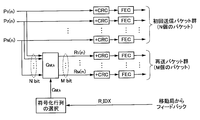
- FIG. 2 is a diagram for explaining generation of an encoded packet in the present embodiment.
- P 1 , P 2 ,..., P N are assumed as a plurality of packets (N packets) at the time of new transmission from the base station to the mobile station.
- a CRC Cyclic Redundancy Check
- FEC Forward Error Correction
- a reception index R_IDX is fed back from the mobile station, and an encoding method is selected according to this reception index.
- the encoding method is expressed by the following equation (1) by an M ⁇ N encoding matrix G M, k.
- k is a number assigned in order to identify a plurality of coding matrices G M, k having the same error number M.
- P 1 (n), P 2 (n),..., P N (n) are the n-th bits from N packets P 1 , P 2 ,. It is assumed that one bit is extracted in order. Then, N bits R 1 (n), R 2 (n),..., R N (n) are obtained by multiplying the extracted N bits by the M ⁇ N coding matrix G M, k. can get.
- M matrix retransmission packets (encoded packets) are generated by performing this matrix operation for each bit of the N packets. In the above formula (1), all calculations are performed with mod2.
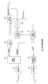
- FIG. 3 is a block diagram showing the main part of the internal configuration of the mobile station.
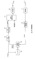
- FIG. 4 is a block diagram showing a main part of the internal configuration of the base station.
- the mobile station includes a receiver 31, a signal separation unit 32, an FEC decoding unit 33, a packet decoding unit 34, an error detection unit 35, a buffer 36, and a retransmission control unit. 37, a control signal generator 38, and a transmitter 39.
- the signal separation unit 32 separates the data signal and the control signal from the baseband signal obtained by the receiver 31.
- OFDM Orthogonal Frequency Division Multiple
- the signal separation unit 32 generates a symbol sequence of each subcarrier by FFT processing. Then, the data signal and the control signal inserted in a predetermined subcarrier are separated.
- the data signal obtained by the signal separation unit 32 is demodulated and then output to the FEC decoding unit 33.
- the control signal obtained by the signal separation unit 32 is demodulated and then output to the retransmission control unit 37.
- the FEC decoding unit 33 sequentially decodes the data signal from the signal demultiplexing unit 32 in units of packets by a decoding method corresponding to the error correction coding performed in the base station.
- the error detection unit 35 performs error detection using the CRC bits added to the packet.
- the error detection unit 35 outputs an ACK signal (successful reception) or a NACK signal (reception error) in units of packets to the retransmission control unit 37 as an error detection result.
- the successful reception packet is output to the upper layer and stored in the buffer 36.
- the packet decoding unit 34 decodes the encoded packet transmitted from the base station at the time of packet retransmission with the reception success packet in the buffer 36 under the control of the retransmission control unit 37. This decoding process will be described in detail later.
- retransmission control unit 37 determines whether the received packet is a packet received for the first time (a packet at the time of new transmission from the base station) or an encoded packet at the time of retransmission. . Then, the retransmission control unit 37 controls the packet decoding unit 34 when the received packet is an encoded packet.
- a unique reception index (identification information) is associated in advance between each mobile station and base station for each combination of reception success or reception error of a plurality of packets. Then, the retransmission control unit 37 specifies the reception index based on the error detection result of each packet in the error detection unit 35. This reception index R_IDX is multiplexed with the control signal by the control signal generator 38 and transmitted to the base station by the transmitter 39.
- a receiver 11 As shown in FIG. 4, a receiver 11, a control signal extraction unit 12, a retransmission control unit 13, a buffer 14, a CRC adding unit 15, an FEC encoding unit 16, and a signal multiplexing unit 17
- the transmitter 18 is provided.
- the receiver 11 converts the received RF signal into a digital baseband signal.
- the control signal extraction unit 12 extracts a control signal by performing predetermined signal separation processing and demodulation / decoding processing on the baseband signal.
- This control signal includes a reception index corresponding to reception results of a plurality of packets transmitted to the mobile station.
- the control signal extraction unit 12 outputs the reception index R_IDX to the retransmission control unit 13.
- a plurality of packets to be transmitted to the mobile station are stored in the buffer 14 for retransmission control prior to new transmission.
- the retransmission control unit 13 selects one of a plurality of encoding methods provided based on the reception index from the control signal extraction unit 12 at the time of packet retransmission. Furthermore, the retransmission control unit 13 generates an encoded packet from a plurality of packets in the buffer 14 according to the selected encoding method. At this time, the retransmission control unit 13 determines an encoding method that can be decoded by a successful reception packet at the time of new reception in the mobile station from among a plurality of packets to be transmitted in the buffer 14, and transmits by the determined encoding method. Encode multiple packets of interest. This encoding process will be described later in detail.
- the CRC adding unit 15 adds a CRC bit for error detection to a newly input packet or an encoded packet from the retransmission control unit 13.
- the FEC encoding unit 16 performs encoding for error correction, which is defined in advance with the mobile station, on each packet to which a CRC bit is added.
- the signal multiplexer 17 multiplexes the data signal (packet) from the FEC encoder 16 and the control signal to generate a baseband signal to be transmitted. For example, when the OFDMA communication method is adopted, the signal of each subcarrier is converted into a time domain signal by IFFT (Inverse Fast Fourier Transform) processing.
- the transmitter 18 radiates the baseband signal from the signal multiplexing unit 17 from the antenna to the space after up-converting the baseband frequency to the radio frequency.
- FIG. 5 is a diagram illustrating a relationship between a plurality of error patterns (combinations) assumed in four packets and a reception index R_IDX corresponding to each error pattern.
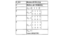
- FIG. 6 is a diagram illustrating a correspondence relationship with an encoding method (encoding matrix) applied in the base station according to the reception index R_IDX.
- the operations described below are all bit operations (MOD2 operations).
- reception states (ACK or NACK) at the mobile station (error patterns 0 to 15).
- ACK or NACK reception states
- a reception index R_IDX is associated with each of the 16 error patterns in advance as shown in FIG.
- the retransmission control unit 37 of the mobile station receives the reference based on the reception state (ACK or NACK) of each packet given from the error detection unit 35 with reference to the correspondence relationship shown in FIG.
- the index R_IDX is determined, and the reception index is fed back to the base station.
- the correspondence relationship between the reception index R_IDX and the encoding matrix shown in FIG. 6 is information known in advance in the base station.
- the retransmission controller 13 (see FIG. 4) of the base station selects an encoding method (encoding matrix) at the time of retransmission based on the reception index R_IDX fed back from the mobile station. Then, an encoded packet is generated.
- N 4, and a matrix of M ⁇ 4 (M: number of errors) is set as the encoding matrix GM , k .
- the number of encoded packets to be generated is the same as the number of reception error packets.
- the mobile station for successful reception packet (three packets) it is known, when receiving the coded packet R 1, cancels (subtracts) the three successful reception packet from the encoded packet R 1. As described above, since all operations are performed with mod 2 in the present embodiment, cancellation is the same as addition, not subtraction. As a result, the mobile station correctly reproduces (decodes) what was a reception error packet at the time of new transmission. For example, if the packet P 4 is a reception error packet, the packet P 4 is regenerated by performing the following equation (4).
- the encoded packet R 1 is the sum of all the packets P 1 , P 2 , P 3 , and P 4 , the encoded packet R 1 is used regardless of which packet is the reception error packet at the time of new transmission. The same is true in that a reception error packet is correctly reproduced by canceling three reception success packets.
- reception indexes fed back to the base station have the same value (“1”) for four error patterns with the number of errors “1”. That is, information on which of the four packets is a reception error packet is not transmitted from the mobile station to the base station. Therefore, the amount of feedback information is reduced in the system according to the present embodiment as compared with the system that feeds back the reception states (ACK / NACK) of all packets (requires 4 bits).
- reception success packets two packets P 3 and P 4
- two receptions are received from the encoded packets R 1 and R 2.
- Cancel (subtract) the success packet As a result, as shown in Expression (6), encoded packets R 1 ′ and R 2 ′ after cancellation are obtained.
- packet P 1 is obtained as encoded packet R 2 ′
- packet P 2 is obtained by subtracting packet P 1 (ie, R 2 ′) from encoded packet R 1 ′.
- P 1 and P 2 are calculated from R 1 ′ and R 2 ′.
- the packets P 1 and P 4 are reproduced (decoded) in the same manner as the error pattern “5”.
- the packets P 2 and P 3 are reproduced (decoded) in the same manner as the error pattern “5”.
- the packets P 3 and P 4 are reproduced (decoded) in the same manner as the error pattern “5”.
- the encoding matrix G 2,1 (that is, another reception index) different from the cases of the error patterns “5”, “7”, “8”, and “10”.
- the encoded packets R 1 ′ and R 2 ′ are expressed by the following equation (5). (12).
- the encoding matrix G 2,1 is selected, the packets P 1 , P 3 cannot be uniquely determined. This is because the matrix on the right side of Equation (12) does not have an inverse matrix. Therefore, in the case of the error pattern “6”, the encoding matrix G 2,1 different from G 2,0 is set so that the matrix obtained after canceling the reception success packet from the encoded packet has an inverse matrix. Is set.
- Error pattern “14” (ACK, NACK, NACK, NACK)
- the error pattern is “14”
- the canceled encoded packets R 1 ′, R 2 ′, R 3 ′ is as shown in Expression (23).
- the determinant of the matrix shown in Expression (23) is not “0” as shown in Expression (24). Therefore, the packets P 2 , P 3 , and P 4 can be reproduced (decoded) from the equation (23).
- the amount of feedback information is reduced in the system according to the present embodiment as compared with the system that feeds back the reception states (ACK / NACK) of all packets (requires 4 bits).
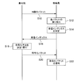
- FIG. 7 is a flowchart showing the operation of transmitting a plurality of packets from the base station to the mobile station. In the description of the operation, each part shown in FIGS. 3 and 4 is referred to as appropriate.
- N packets are transmitted from the base station to the mobile station (step S10).
- the error detector 35 detects an error of each packet (step S12), and the error detection result is output to the retransmission controller 37.
- the retransmission control unit 37 of the mobile station specifies the reception index R_IDX based on the error detection result (ACK / NACK) of each packet (step S14). Note that the error detection result (ACK / NACK) (that is, error pattern) of each packet and the reception index are associated in advance in the base station.
- the mobile station transmits the specified reception index to the base station (step S16).
- the retransmission control unit 13 defines in advance the correspondence between the reception index and the encoding method (encoding matrix). Therefore, the retransmission control unit 13 of the base station determines an encoding method based on the reception index transmitted in step S16, and executes encoding (step S18). Specifically, the retransmission control unit 13 of the base station multiplies the N transmission packets by the determined M ⁇ N (M: number of errors) encoding matrix in units of bits to obtain M encoded packets. Is generated. These M encoded packets are transmitted to the mobile station (step S20).
- the mobile station receives M encoded packets. Further, the mobile station reproduces the reception error packet in step S12 by decoding the encoded packet (step S22). Specifically, the packet decoding unit 34 of the mobile station cancels the reception success packet in step S12 from the encoded packet (bit level subtraction), thereby reproducing the reception error packet.
- Coding matrix setting method for an arbitrary number of packets In the above (4), with regard to the encoding and decoding of packets at the time of retransmission, an example in which the number of packets to be transmitted is 4 is specifically described As described above, an encoding matrix can be set appropriately for an arbitrary number of packets. Hereinafter, a method for setting an encoding matrix for an arbitrary number of packets will be described by a simple method. In this setting method, when the number of packets to be transmitted is N, the encoding matrix for each of the reception error numbers M (M: 1 to N ⁇ 1) of N packets is sequentially changed according to the following steps. Calculate.
- ⁇ Step A A component of an M ⁇ N coding matrix for a specific error number M is generated by a random number of 0 or 1, and a coding matrix is generated.
- ⁇ Step B When M reception errors occur in N packets, there are N C M error patterns. For each of the N C M error patterns, it is confirmed whether a received error packet can be reproduced (decoded) from the encoded packet (retransmission packet) based on the encoding matrix generated in step 1. Specifically, among the columns of the encoding matrix generated in step 1, a degenerate matrix (M ⁇ M square matrix) in which M columns corresponding to the coefficient sequence multiplied by the reception error packet in the encoding process are left. Is generated.
- Step C If there are P reception error packets that cannot be reproduced in step 2 among the N C M error patterns, a new encoding matrix is generated with random numbers, and the P reception error packets can be reproduced. Classify into error patterns and unreproducible error patterns. A new encoding matrix is generated with random numbers until all N C M error patterns can be reproduced. That is, the number of coding matrices is increased until all N C M error patterns can be reproduced.
- the encoding matrix for all the error numbers M can be obtained by performing the processes of steps A to C in order for each error number M.
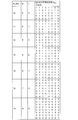
- FIG. 8 shows an encoding matrix in which the number of errors M in eight transmission packets is 1 to 4
- FIG. 9 is an encoding in which the number of errors M in eight transmission packets is 5 to 8. Indicates a matrix.
- encoding is performed such that the number of encoding matrices is minimized with respect to the number N of packets to be transmitted by trying the encoding matrix, for example, about 10,000,000 times according to the above steps while changing random numbers.
- a method (that is, an encoding method that minimizes the amount of feedback information) can be searched.
- identification information corresponds in advance to a plurality of packets transmitted from the base station for each combination of reception results of each packet in the mobile station. It is attached. This identification information is fed back to the base station. Then, paying attention to the fact that the successful reception packet at the time of new transmission is known in the mobile station, the packet retransmitted from the base station is transmitted by an encoding method that can be decoded by the successful reception packet at the time of new reception at the mobile station. A plurality of target packets are encoded (encoded packets). The mobile station decodes the encoded packet with the reception success packet at the time of new reception, and reproduces a reception error packet at the time of new reception.
- the number of identification information (that is, the number of encoding methods) can be reduced from the number of packets to be transmitted, and the amount of feedback information to the base station can be reduced.
- the reduction is as described above.
- BS base station (first communication device, transmission device), 11: receiver, 12: control signal extraction unit, 13: retransmission control unit, 14: buffer, 15 ... CRC adding unit, 16 ... FEC encoding unit, 17 ... Signal multiplexing unit, 18 ... transmitter MS ... mobile station (second communication device, receiving device), 31 ... receiver, 32 ... signal separation unit, 33 ... FEC decoding unit, 34 ... packet decoding unit, 35 ... error detection 36, buffer, 37 ... retransmission control unit, 38 ... control signal generation unit, 39 ... transmitter
Landscapes
- Engineering & Computer Science (AREA)
- Computer Networks & Wireless Communication (AREA)
- Signal Processing (AREA)
- Detection And Prevention Of Errors In Transmission (AREA)
- Mobile Radio Communication Systems (AREA)
Abstract
複数のパケットの受信の成功又は誤りについて、受信側の第2通信装置から送信側の第1通信装置へフィードバックする情報量を低下させることができる通信方法が提供される。第1通信装置は、第2通信装置から送信された識別情報に基づいて、第2通信装置における新規受信時の受信成功パケットによって復号可能な符号化方法で、複数のパケットを符号化し、符号化パケットを第2通信装置へ再送信する。第2通信装置は、符号化パケットを新規受信時の受信成功パケットによって復号し、新規受信時の受信誤りパケットを再生する。
Description
本発明は、パケットの受信側の通信装置からパケットの送信側の通信装置に対し、パケットの受信成功/受信誤りに関する情報をフィードバックする技術に関する。
送信装置から送信されたパケットが受信装置において誤って受信された場合に、受信装置からACK(受信成功)又はNACK(受信誤り)を送信装置へフィードバックし、送信装置から再度、受信誤りパケットを再送するパケット通信システムが知られている。例えば特許文献1では、送信装置が複数のパケットを送信し、受信装置が各パケットに対するACK/NACKを一括してフィードバックする技術が開示されている。
上述した従来の通信システムでは、パケットの受信装置から送信装置へフィードバックする情報は、パケットごとのACK/NACK(1ビット)の情報である。したがって、送信装置へフィードバックする情報量は、送信対象のパケット数と同ビット数である。
ところで、3GPP(3rd Generation Partnership Project)で検討が進められているLTE(Long Term Evolution)などのセルラ通信システムでは、干渉雑音やマルチパスフェージング環境などの影響により、パケットの受信誤り率が比較的高い状態で運用される場合が多く、パケット再送の発生率が高い。また、セルラ通信システムの下りリンクでは、同一のサブフレームに多数のユーザ(移動局)向けのデータが多重化され、その多数の移動局からのACK/NACKの情報が基地局へフィードバックされる。かかる通信システムでは、基地局へフィードバックする情報量が多いほど無線リソースが消費される。したがって、上述したフィードバック情報量を低減することが要請される。
よって、複数のパケットの受信の成功又は誤りについて、受信側の通信装置から送信側の通信装置へフィードバックする情報量を低下させることができる通信方法、通信システム、送信装置、受信装置を提供することが課題である。
第1の観点では、第1通信装置から第2通信装置へ複数のパケットを送信するときの通信方法が提供される。第2通信装置における各パケットの受信結果の組合せごとに予め、前記複数のパケットの数より少ない数の識別情報が対応付けられている。
この通信方法は、第1通信装置が、第2通信装置へ複数のパケットを新規送信する第1ステップと、第2通信装置が、前記複数のパケットの新規受信時の受信結果に基づいて第1識別情報を特定し、前記第1識別情報を第1通信装置へ送信する第2ステップと、第1通信装置が、前記第1識別情報に基づいて、第2通信装置における新規受信時の受信成功パケットによって復号可能な符号化方法を決定し、決定した前記符号化方法で前記複数のパケットを符号化し、符号化パケットを第2通信装置へ再送信する第3ステップと、第2通信装置が、前記符号化パケットを新規受信時の受信成功パケットによって復号し、新規受信時の受信誤りパケットを再生する第4ステップと、を備える。
この通信方法は、第1通信装置が、第2通信装置へ複数のパケットを新規送信する第1ステップと、第2通信装置が、前記複数のパケットの新規受信時の受信結果に基づいて第1識別情報を特定し、前記第1識別情報を第1通信装置へ送信する第2ステップと、第1通信装置が、前記第1識別情報に基づいて、第2通信装置における新規受信時の受信成功パケットによって復号可能な符号化方法を決定し、決定した前記符号化方法で前記複数のパケットを符号化し、符号化パケットを第2通信装置へ再送信する第3ステップと、第2通信装置が、前記符号化パケットを新規受信時の受信成功パケットによって復号し、新規受信時の受信誤りパケットを再生する第4ステップと、を備える。
第2の観点では、第1通信装置と第2通信装置を備え、第1通信装置から第2通信装置へ複数のパケットが送信される通信システムが提供される。第2通信装置における各パケットの受信結果の組合せごとに予め、前記複数のパケットの数より少ない数の識別情報が対応付けられている。
第1通信装置は、第2通信装置へ複数のパケットを新規送信する第1送信部と、第2通信装置から前記識別情報を受信する第1受信部と、第2通信装置から受信する識別情報に基づき、第2通信装置における新規受信時の受信成功パケットによって復号可能な符号化方法を決定し、決定した前記符号化方法で前記複数のパケットを符号化して符号化パケットを生成するパケット符号化部と、前記符号化パケットを第2通信装置へ再送信する第2送信部と、を有する。
第2通信装置は、第1通信装置から複数のパケットを新規受信する第2受信部と、前記複数のパケットの受信結果に基づいて第1識別情報を特定する情報特定部と、前記第1識別情報を第1通信装置へ送信する第3送信部と、第1通信装置から送信される前記符号化パケットを受信する第3受信部と、第1通信装置から送信される前記符号化パケットを新規受信時の受信成功パケットによって復号し、新規受信時の受信誤りパケットを再生するパケット復号部と、を有する。
第1通信装置は、第2通信装置へ複数のパケットを新規送信する第1送信部と、第2通信装置から前記識別情報を受信する第1受信部と、第2通信装置から受信する識別情報に基づき、第2通信装置における新規受信時の受信成功パケットによって復号可能な符号化方法を決定し、決定した前記符号化方法で前記複数のパケットを符号化して符号化パケットを生成するパケット符号化部と、前記符号化パケットを第2通信装置へ再送信する第2送信部と、を有する。
第2通信装置は、第1通信装置から複数のパケットを新規受信する第2受信部と、前記複数のパケットの受信結果に基づいて第1識別情報を特定する情報特定部と、前記第1識別情報を第1通信装置へ送信する第3送信部と、第1通信装置から送信される前記符号化パケットを受信する第3受信部と、第1通信装置から送信される前記符号化パケットを新規受信時の受信成功パケットによって復号し、新規受信時の受信誤りパケットを再生するパケット復号部と、を有する。
第3の観点では、受信装置へ複数のパケットを送信する送信装置が提供される。
この送信装置は、受信装置へ複数のパケットを新規送信する第1送信部と、受信装置から、受信装置における各パケットの受信結果の組合せに対応する識別情報を受信する第1受信部と、受信装置から受信する識別情報に基づき、受信装置における前記複数のパケットの新規受信時の受信成功パケットによって復号可能な符号化方法を決定し、決定した前記符号化方法で前記複数のパケットを符号化するパケット符号化部と、前記符号化パケットを受信装置へ再送信する第2送信部と、を備える。
この送信装置は、受信装置へ複数のパケットを新規送信する第1送信部と、受信装置から、受信装置における各パケットの受信結果の組合せに対応する識別情報を受信する第1受信部と、受信装置から受信する識別情報に基づき、受信装置における前記複数のパケットの新規受信時の受信成功パケットによって復号可能な符号化方法を決定し、決定した前記符号化方法で前記複数のパケットを符号化するパケット符号化部と、前記符号化パケットを受信装置へ再送信する第2送信部と、を備える。
第4の観点では、送信装置から複数のパケットを受信する受信装置が提供される。この受信装置では、複数のパケットの各パケットの受信結果の組合せごとに予め、前記複数のパケットの数より少ない数の識別情報が対応付けられている。
この受信装置は、送信装置から複数のパケットを新規受信する第2受信部と、前記複数のパケットの受信結果に基づいて第1識別情報を特定する情報特定部と、前記第1識別情報を送信装置へ送信する第3送信部と、前記第1識別情報に基づき、新規受信時の受信成功パケットによって復号可能な符号化方法で前記複数のパケットが符号化され、送信装置から送信される符号化パケット、を受信する第3受信部と、前記符号化パケットを新規受信時の受信成功パケットによって復号し、新規受信時の受信誤りパケットを再生するパケット復号部と、を備える。
この受信装置は、送信装置から複数のパケットを新規受信する第2受信部と、前記複数のパケットの受信結果に基づいて第1識別情報を特定する情報特定部と、前記第1識別情報を送信装置へ送信する第3送信部と、前記第1識別情報に基づき、新規受信時の受信成功パケットによって復号可能な符号化方法で前記複数のパケットが符号化され、送信装置から送信される符号化パケット、を受信する第3受信部と、前記符号化パケットを新規受信時の受信成功パケットによって復号し、新規受信時の受信誤りパケットを再生するパケット復号部と、を備える。
開示の通信方法、通信システム、送信装置、受信装置によれば、複数のパケットの受信の成功又は誤りについて、受信側の通信装置から送信側の通信装置へフィードバックする情報量を低下させることができる。
以下の実施形態では、本発明の一実施形態に係る通信システムとして、第1通信装置又は送信装置としての基地局と、第2通信装置又は受信装置としての移動局とが含まれる無線通信システムについて説明する。
(1)実施形態の無線通信システム
図1は、本実施形態の無線通信システムを示す図である。図1に示すように、本実施形態の無線通信システムには、基地局(BS:Base Station)と、無線基地局のサービスエリア内に存在する移動局(MS:Mobile Station)とが含まれる。本実施形態では、基地局から移動局に対し、複数のパケットを送信する場合を例として説明する。
図1は、本実施形態の無線通信システムを示す図である。図1に示すように、本実施形態の無線通信システムには、基地局(BS:Base Station)と、無線基地局のサービスエリア内に存在する移動局(MS:Mobile Station)とが含まれる。本実施形態では、基地局から移動局に対し、複数のパケットを送信する場合を例として説明する。
この無線通信システムでは、基地局から移動局に対して2以上の所定数のパケット(複数のパケット)単位でパケット送信が行われる。移動局は、この複数のパケットの各々に対してACK(受信成功)又はNACK(受信誤り)を判定し、基地局へフィードバックする。ここで、基地局と移動局の間では、移動局における各パケットの受信成功又は受信誤りの組合せごとに予め、識別情報が対応付けられている。この識別情報を、本実施形態の説明では「受信インデックス」と表記する。移動局は、基地局へのフィードバックを、複数のパケットの受信結果に対応する受信インデックスにより行う。
この無線通信システムでは、基地局は、移動局からフィードバックされた受信インデックスに基づいて、第2通信装置における新規受信時の受信成功パケットによって復号可能な符号化方法を決定し、決定した符号化方法で送信対象の複数のパケットを符号化する。そして、この符号化パケットが移動局へ送信される。移動局は、基地局から与えられる符号化パケットを、新規送信時の受信成功パケットによって復号することで、新規送信時の受信誤りパケットを再生する。
(2)符号化パケットの生成
次に、符号化パケットの生成について図2を参照して説明する。図2は、本実施形態における符号化パケットの生成を説明するための図である。
図2において、基地局から移動局に対する新規送信時の複数のパケット(N個のパケット)としてP1,P2,…,PNを想定する。新規送信時には、この複数のパケットに対して誤り検出のためのCRC(Cyclic Redundancy Check)コードが付加され(+CRC)、FEC(Forward Error Correction)符号化(FEC)が行われて移動局へ送信される。再送時には、移動局から受信インデックスR_IDXがフィードバックされ、この受信インデックスに応じて符号化方法が選択される。
次に、符号化パケットの生成について図2を参照して説明する。図2は、本実施形態における符号化パケットの生成を説明するための図である。
図2において、基地局から移動局に対する新規送信時の複数のパケット(N個のパケット)としてP1,P2,…,PNを想定する。新規送信時には、この複数のパケットに対して誤り検出のためのCRC(Cyclic Redundancy Check)コードが付加され(+CRC)、FEC(Forward Error Correction)符号化(FEC)が行われて移動局へ送信される。再送時には、移動局から受信インデックスR_IDXがフィードバックされ、この受信インデックスに応じて符号化方法が選択される。
ここで、N個のパケットの中の受信誤りパケットの数をM個としたときに、符号化方式は、M×Nの符号化行列GM,kにより、下記式(1)のとおり表される。なお、kは、誤り数Mが同一の複数の符号化行列GM,kを識別するために順に付される番号である。

式(1)において、P1(n),P2(n),…,PN(n)が、N個のパケットP1,P2,…,PNから、それぞれのn番目のビットを順に1ビットずつ抽出したものとする。そして、抽出した計Nビットに対してM×Nの符号化行列GM,kを掛けることにより、N個のビットR1(n),R2(n),…,RN(n)が得られる。この行列演算を、N個のパケットの各ビットについてすべて行うことによりM個の再送パケット(符号化パケット)が生成される。上記数式(1)において演算は、全てmod2で行う。
(3)基地局及び移動局の構成
次に、本実施形態の無線通信システムにおける基地局(送信装置)及び移動局(受信装置)の構成について、図3及び図4を参照して説明する。図3は、移動局の内部構成の要部を示すブロック図である。図4は、基地局の内部構成の要部を示すブロック図である。
次に、本実施形態の無線通信システムにおける基地局(送信装置)及び移動局(受信装置)の構成について、図3及び図4を参照して説明する。図3は、移動局の内部構成の要部を示すブロック図である。図4は、基地局の内部構成の要部を示すブロック図である。
・移動局(受信装置)の構成
図3に示すように、移動局は、受信機31、信号分離部32、FEC復号部33、パケット復号部34、誤り検出部35、バッファ36、再送制御部37、制御信号生成部38、送信機39を備える。
図3に示すように、移動局は、受信機31、信号分離部32、FEC復号部33、パケット復号部34、誤り検出部35、バッファ36、再送制御部37、制御信号生成部38、送信機39を備える。
信号分離部32は、受信機31により得られたベースバンド信号から、データ信号、制御信号を分離する。例えばOFDM
(Orthogonal Frequency Division Multiple)通信方式を採る場合には、この信号分離部32においてFFT処理により各サブキャリアのシンボル列が生成される。そして、所定のサブキャリアに挿入されているデータ信号、制御信号を分離することが行われる。
信号分離部32により得られたデータ信号は、復調された後、FEC復号部33へ出力される。信号分離部32により得られた制御信号は、復調された後、再送制御部37へ出力される。
(Orthogonal Frequency Division Multiple)通信方式を採る場合には、この信号分離部32においてFFT処理により各サブキャリアのシンボル列が生成される。そして、所定のサブキャリアに挿入されているデータ信号、制御信号を分離することが行われる。
信号分離部32により得られたデータ信号は、復調された後、FEC復号部33へ出力される。信号分離部32により得られた制御信号は、復調された後、再送制御部37へ出力される。
FEC復号部33は、基地局で行われる誤り訂正符号化に対応した復号化方法により、信号分離部32からのデータ信号をパケット単位で順次、復号化を施す。
誤り検出部35は、パケットに付加されているCRCビットを用いて、誤り検出を行う。誤り検出部35では、誤り検出結果として、パケット単位でのACK信号(受信成功)又はNACK信号(受信誤り)を再送制御部37へ出力する。受信成功パケットは、上位のレイヤーへ出力されるとともに、バッファ36に格納される。
誤り検出部35は、パケットに付加されているCRCビットを用いて、誤り検出を行う。誤り検出部35では、誤り検出結果として、パケット単位でのACK信号(受信成功)又はNACK信号(受信誤り)を再送制御部37へ出力する。受信成功パケットは、上位のレイヤーへ出力されるとともに、バッファ36に格納される。
パケット復号部34は、再送制御部37による制御の下、パケット再送時に基地局から送信される符号化パケットを、バッファ36内の受信成功パケットにより復号する。この復号処理については、後に詳しく説明する。
再送制御部37は、受信された制御信号に基づき、受信したパケットが、初めて受信するパケット(基地局からの新規送信時のパケット)であるのか、再送時の符号化パケットであるのかを判別する。そして、再送制御部37は、受信したパケットが符号化パケットである場合に、パケット復号部34を制御する。
また、この無線通信システムにおいて、移動局と基地局との間では、複数のパケットの各々の受信成功又は受信誤りの組合せごとに予め固有の受信インデックス(識別情報)が対応付けられている。そして、再送制御部37は、誤り検出部35における各パケットの誤り検出結果に基づいて受信インデックスを特定する。この受信インデックスR_IDXは、制御信号生成部38により制御信号に多重化され、送信機39により基地局へ送信される。
また、この無線通信システムにおいて、移動局と基地局との間では、複数のパケットの各々の受信成功又は受信誤りの組合せごとに予め固有の受信インデックス(識別情報)が対応付けられている。そして、再送制御部37は、誤り検出部35における各パケットの誤り検出結果に基づいて受信インデックスを特定する。この受信インデックスR_IDXは、制御信号生成部38により制御信号に多重化され、送信機39により基地局へ送信される。
・基地局(送信装置)の構成
図4に示すように、受信機11、制御信号抽出部12、再送制御部13、バッファ14、CRC付与部15、FEC符号化部16、信号多重化部17、送信機18を備える。
図4に示すように、受信機11、制御信号抽出部12、再送制御部13、バッファ14、CRC付与部15、FEC符号化部16、信号多重化部17、送信機18を備える。
受信機11は、受信したRF信号をデジタルベースバンド信号に変換する。制御信号抽出部12は、このベースバンド信号に対し、所定の信号分離処理及び復調・復号処理を行うことで制御信号を抽出する。この制御信号には、移動局へ送信した複数のパケットの受信結果に対応する受信インデックスが含まれている。制御信号抽出部12は、この受信インデックスR_IDXを再送制御部13へ出力する。
移動局への送信対象となる複数のパケットは、新規送信に先立って、再送制御のためにバッファ14に格納される。
再送制御部13は、パケット再送時に、制御信号抽出部12からの受信インデックスに基づいて、複数設けられる符号化方法の中のいずれかを選択する。さらに、再送制御部13は、選択した符号化方法に従い、バッファ14内の複数のパケットから符号化パケットを生成する。このとき、再送制御部13は、バッファ14内の送信対象の複数のパケットの内、移動局における新規受信時の受信成功パケットによって復号可能な符号化方法を決定し、決定した符号化方法で送信対象の複数のパケットを符号化する。この符号化処理については、後に詳しく説明する。
再送制御部13は、パケット再送時に、制御信号抽出部12からの受信インデックスに基づいて、複数設けられる符号化方法の中のいずれかを選択する。さらに、再送制御部13は、選択した符号化方法に従い、バッファ14内の複数のパケットから符号化パケットを生成する。このとき、再送制御部13は、バッファ14内の送信対象の複数のパケットの内、移動局における新規受信時の受信成功パケットによって復号可能な符号化方法を決定し、決定した符号化方法で送信対象の複数のパケットを符号化する。この符号化処理については、後に詳しく説明する。
CRC付与部15は、新規に入力するパケット、又は再送制御部13からの符号化パケットに対して誤り検出のためのCRCビットを付与する。FEC符号化部16は、CRCビットが付与された各パケットに対して、移動局との間で予め規定された、誤り訂正のための符号化を行う。
信号多重化部17は、FEC符号化部16からのデータ信号(パケット)と、制御信号とを多重化して、送信すべきベースバンド信号を生成する。例えばOFDMA通信方式を採る場合には、IFFT(Inverse Fast Fourier Transform)処理による各サブキャリアの信号の時間領域信号への変換が行われる。送信機18は、信号多重化部17からのベースバンド信号を、ベースバンド周波数から無線周波数へアップコンバート等した後に、アンテナから空間へ放射する。
(4)再送時のパケット符号化処理と復号処理の具体例
次に、再送時のパケットの符号化処理と復号処理に関し、送信対象のパケット数が4である場合を例に、図5及び図6を参照して具体的に説明する。図5は、4個のパケットで想定される複数の誤りパターン(組合せ)と、各誤りパターンに対応する受信インデックスR_IDXとの関係を示す図である。図6は、受信インデックスR_IDXに応じて基地局で適用される符号化方法(符号化行列)との対応関係を示す図である。
なお、以下で説明する演算は、すべてビット演算(MOD2演算)である。
次に、再送時のパケットの符号化処理と復号処理に関し、送信対象のパケット数が4である場合を例に、図5及び図6を参照して具体的に説明する。図5は、4個のパケットで想定される複数の誤りパターン(組合せ)と、各誤りパターンに対応する受信インデックスR_IDXとの関係を示す図である。図6は、受信インデックスR_IDXに応じて基地局で適用される符号化方法(符号化行列)との対応関係を示す図である。
なお、以下で説明する演算は、すべてビット演算(MOD2演算)である。
図5に示すように、基地局からの4個のパケットP1,P2,P3,P4に対して、移動局での受信状態(ACK又はNACK)は16通り(誤りパターン0~15)が想定される。移動局では、この16個の誤りパターンの各々に対して、図5に示すように予め受信インデックスR_IDXが対応付けられている。
ここで再度図3を参照すると、移動局の再送制御部37は、誤り検出部35から与えられる各パケットの受信状態(ACK又はNACK)に基づいて、図5に示す対応関係を参照して受信インデックスR_IDXを決定し、受信インデックスを基地局へフィードバックする。
ここで再度図3を参照すると、移動局の再送制御部37は、誤り検出部35から与えられる各パケットの受信状態(ACK又はNACK)に基づいて、図5に示す対応関係を参照して受信インデックスR_IDXを決定し、受信インデックスを基地局へフィードバックする。
図6に示す、受信インデックスR_IDXと符号化行列との対応関係は、予め基地局において既知の情報である。ここで、再度図2を参照すると、基地局の再送制御部13(図4参照)は、移動局からフィードバックされる受信インデックスR_IDXに基づいて、再送時の符号化方法(符号化行列)を選択し、符号化パケットを生成する。ここでは、N=4であり、符号化行列GM,kとしてM×4(M:誤り数)の行列が設定されている。生成される符号化パケットの数は、受信誤りパケットの数と同数である。
(4-1)誤り数が「0」の場合
この場合、移動局から基地局に対して受信インデックスR_IDXとして「0」がフィードバックされる。これにより、基地局は、すべてのパケットが受信成功であることを認識し、パケットの再送を行わない。
この場合、移動局から基地局に対して受信インデックスR_IDXとして「0」がフィードバックされる。これにより、基地局は、すべてのパケットが受信成功であることを認識し、パケットの再送を行わない。
(4-2)誤り数が「1」の場合
このとき、図5に示すように、4個のパケットの内いずれのパケットが受信誤りであった場合でも、移動局から基地局に対し、受信インデックスR_IDXとして「1」がフィードバックされる。そして、図6に示すように、基地局は、フィードバックされた受信インデックスに対応する符号化行列G1,0を選択して、符号化パケットを生成する。
具体的には、選択される符号化行列G1,0は、以下の式(2)に示すものであるため、符号化パケットをR1とすると、R1は式(3)に示すとおりとなる。この1個の符号化パケットR1が再送パケットとして移動局へ送信される。ここでR1やP1、P2、P3、P4などは、数式(1)と同様にn番目のビットを表すが、以下の説明では全てのビットで同様の処理として説明するため、因数のnを省略して記載する。
このとき、図5に示すように、4個のパケットの内いずれのパケットが受信誤りであった場合でも、移動局から基地局に対し、受信インデックスR_IDXとして「1」がフィードバックされる。そして、図6に示すように、基地局は、フィードバックされた受信インデックスに対応する符号化行列G1,0を選択して、符号化パケットを生成する。
具体的には、選択される符号化行列G1,0は、以下の式(2)に示すものであるため、符号化パケットをR1とすると、R1は式(3)に示すとおりとなる。この1個の符号化パケットR1が再送パケットとして移動局へ送信される。ここでR1やP1、P2、P3、P4などは、数式(1)と同様にn番目のビットを表すが、以下の説明では全てのビットで同様の処理として説明するため、因数のnを省略して記載する。


移動局では、受信成功パケット(3個のパケット)が既知であるため、符号化パケットR1を受信すると、符号化パケットR1から3個の受信成功パケットをキャンセル(減算)する。なお、前述したように本実施形態では全て演算をmod2で行うため、キャンセルは、減算でなく加算としても同じである。これにより、移動局では、新規送信時に受信誤りパケットであったものが正しく再生(復号)される。例えば、パケットP4が受信誤りパケットであったとしたならば、以下式(4)の演算を行うことにより、パケットP4が再生される。

符号化パケットR1は、すべてのパケットP1,P2,P3,P4の和となっているため、新規送信時の受信誤りパケットがどのパケットであったとしても、符号化パケットR1から3個の受信成功パケットをキャンセルすることで受信誤りパケットが正しく再生される点は同じである。
ここで注目すべき点は、誤り数が「1」である4個の誤りパターンに対して、基地局へフィードバックされる受信インデックスがすべて同一の値(「1」)であるという点である。すなわち、移動局から基地局に対して、4個のパケットの内、いずれのパケットが受信誤りパケットであるかについての情報は送信されない。よって、すべてのパケットの受信状態(ACK/NACK)をフィードバックするシステム(4ビットが必要)と比較して、本実施形態のシステムでは、フィードバック情報量が低減することになる。
(4-3)誤り数が「2」の場合
この場合、移動局から基地局に対し、受信インデックスR_IDXとして「2」又は「3」がフィードバックされる。そして、基地局は、フィードバックされた受信インデックスに対応する符号化行列G2,0又はG2,1を選択して、符号化パケットを生成する。
この場合、移動局から基地局に対し、受信インデックスR_IDXとして「2」又は「3」がフィードバックされる。そして、基地局は、フィードバックされた受信インデックスに対応する符号化行列G2,0又はG2,1を選択して、符号化パケットを生成する。
・誤りパターン「5」(NACK,NACK,ACK,ACK)
誤りパターンが「5」である場合、図5及び図6に示すように、基地局へフィードバックされる受信インデックスR_IDXは「2」であり、基地局では符号化行列G2,0が選択される。このとき、移動局へ再送される2個の符号化パケットR1,R2は、式(5)に示すとおりとなる。
誤りパターンが「5」である場合、図5及び図6に示すように、基地局へフィードバックされる受信インデックスR_IDXは「2」であり、基地局では符号化行列G2,0が選択される。このとき、移動局へ再送される2個の符号化パケットR1,R2は、式(5)に示すとおりとなる。

移動局では、受信成功パケット(2個のパケットP3,P4)が既知であるため、符号化パケットR1,R2を受信すると、この符号化パケットR1,R2から2個の受信成功パケットをキャンセル(減算)する。これにより、式(6)に示すように、キャンセル後の符号化パケットR1’,R2’が得られる。

式(6)から、パケットP1が符号化パケットR2’として得られ、また、パケットP2が符号化パケットR1’からパケットP1(すなわち、R2’)を減算することで得られることが分かる。換言すれば、式(6)の右辺における行列が逆行列を有するため、R1’,R2’からP1,P2が算出される。
・誤りパターン「7」(NACK,ACK,ACK,NACK)
誤りパターンが「7」である場合、図5及び図6に示すように、基地局へフィードバックされる受信インデックスR_IDXは「2」であり、基地局では符号化行列G2,0が選択される。このとき、2個の符号化パケットR1,R2(式(5))から既知の受信成功パケット(2個のパケットP2,P3)をキャンセルすると、式(7)に示すように、キャンセル後の符号化パケットR1’,R2’が得られる。
誤りパターンが「7」である場合、図5及び図6に示すように、基地局へフィードバックされる受信インデックスR_IDXは「2」であり、基地局では符号化行列G2,0が選択される。このとき、2個の符号化パケットR1,R2(式(5))から既知の受信成功パケット(2個のパケットP2,P3)をキャンセルすると、式(7)に示すように、キャンセル後の符号化パケットR1’,R2’が得られる。

・誤りパターン「8」(ACK,NACK,NACK,ACK)
誤りパターンが「8」である場合、図5及び図6に示すように、基地局へフィードバックされる受信インデックスR_IDXは「2」であり、基地局では符号化行列G2,0が選択される。このとき、2個の符号化パケットR1,R2(式(5))から既知の受信成功パケット(2個のパケットP1,P4)をキャンセルすると、式(8)に示すように、キャンセル後の符号化パケットR1’,R2’が得られる。
誤りパターンが「8」である場合、図5及び図6に示すように、基地局へフィードバックされる受信インデックスR_IDXは「2」であり、基地局では符号化行列G2,0が選択される。このとき、2個の符号化パケットR1,R2(式(5))から既知の受信成功パケット(2個のパケットP1,P4)をキャンセルすると、式(8)に示すように、キャンセル後の符号化パケットR1’,R2’が得られる。

・誤りパターン「10」(ACK,ACK,NACK,NACK)
誤りパターンが「10」である場合、図5及び図6に示すように、基地局へフィードバックされる受信インデックスR_IDXは「2」であり、基地局では符号化行列G2,0が選択される。このとき、2個の符号化パケットR1,R2(式(5))から既知の受信成功パケット(2個のパケットP1,P2)をキャンセルすると、式(9)に示すように、キャンセル後の符号化パケットR1’,R2’が得られる。
誤りパターンが「10」である場合、図5及び図6に示すように、基地局へフィードバックされる受信インデックスR_IDXは「2」であり、基地局では符号化行列G2,0が選択される。このとき、2個の符号化パケットR1,R2(式(5))から既知の受信成功パケット(2個のパケットP1,P2)をキャンセルすると、式(9)に示すように、キャンセル後の符号化パケットR1’,R2’が得られる。

・誤りパターン「6」(NACK,ACK,NACK,ACK)
誤りパターンが「6」である場合、図5及び図6に示すように、基地局へフィードバックされる受信インデックスR_IDXは「3」であり、基地局では符号化行列G2,1が選択される。このとき、移動局へ再送される2個の符号化パケットR1,R2は、式(10)のとおりとなる。
誤りパターンが「6」である場合、図5及び図6に示すように、基地局へフィードバックされる受信インデックスR_IDXは「3」であり、基地局では符号化行列G2,1が選択される。このとき、移動局へ再送される2個の符号化パケットR1,R2は、式(10)のとおりとなる。

移動局では、受信成功パケット(2個のパケットP2,P4)が既知であるため、符号化パケットR1,R2を受信すると、この符号化パケットR1,R2から2個の受信成功パケットをキャンセル(減算)する。これにより、式(11)に示すように、キャンセル後の符号化パケットR1’,R2’が得られる。式(11)から受信誤りパケットP1,P3が再生(復号)される点は、誤りパターン「5」の場合と同様である。

ここで、誤りパターン「6」の場合において、誤りパターン「5」,「7」,「8」,「10」の場合とは別の符号化行列G2,1(すなわち、別の受信インデックス)が選択される理由について説明する。
誤りパターン「6」の場合において、仮に、符号化行列をG2,1でなくG2,0を選択したとすれば、式(5)に基づき符号化パケットR1’,R2’は以下の式(12)のとおりとなる。この式(12)から明らかなように、仮に符号化行列G2,1を選択したとすれば、パケットP1,P3を一意に定めることができない。これは、式(12)の右辺における行列が逆行列を有さないためである。よって、誤りパターン「6」の場合には、符号化パケットから受信成功パケットをキャンセルした後に得られる行列が逆行列を持つように、G2,0とは別の符号化行列G2,1が設定されている。
誤りパターン「6」の場合において、仮に、符号化行列をG2,1でなくG2,0を選択したとすれば、式(5)に基づき符号化パケットR1’,R2’は以下の式(12)のとおりとなる。この式(12)から明らかなように、仮に符号化行列G2,1を選択したとすれば、パケットP1,P3を一意に定めることができない。これは、式(12)の右辺における行列が逆行列を有さないためである。よって、誤りパターン「6」の場合には、符号化パケットから受信成功パケットをキャンセルした後に得られる行列が逆行列を持つように、G2,0とは別の符号化行列G2,1が設定されている。

・誤りパターン「9」(ACK,NACK,ACK,NACK)
誤りパターンが「9」である場合、図5及び図6に示すように、基地局へフィードバックされる受信インデックスR_IDXは「3」であり、基地局では符号化行列G2,1が選択される。このとき、2個の符号化パケットR1,R2(式(10))から既知の受信成功パケット(2個のパケットP1,P3)をキャンセルすると、式(13)に示すように、キャンセル後の符号化パケットR1’,R2’が得られる。式(13)からパケットP2,P4が再生(復号)される。
誤りパターンが「9」である場合、図5及び図6に示すように、基地局へフィードバックされる受信インデックスR_IDXは「3」であり、基地局では符号化行列G2,1が選択される。このとき、2個の符号化パケットR1,R2(式(10))から既知の受信成功パケット(2個のパケットP1,P3)をキャンセルすると、式(13)に示すように、キャンセル後の符号化パケットR1’,R2’が得られる。式(13)からパケットP2,P4が再生(復号)される。

以上、誤り数が「2」の場合についての符号化処理及び復号処理について説明してきた。誤り数が「2」の場合、2×4の符号化行列(第1行列)は、符号化行列を2×2(「2」は誤り数)の正方行列(第2行列)に縮退させたときに、この正方行列が逆行列を有するようにして設定される。この正方行列は、符号化パケットから受信成功パケットをキャンセルした後に得られる行列であり、誤り数が「2」の場合には、以下の式(14)又は(15)(i,j=1~4)のいずれかになる。


本実施形態では、誤り数が「2」である6個の誤りパターンに対して、基地局へフィードバックされる受信インデックス(「2」又は「3」)が2通りに過ぎない。よって、すべてのパケットの受信状態(ACK/NACK)をフィードバックするシステム(4ビットが必要)と比較して、本実施形態のシステムでは、フィードバック情報量が低減することになる。
(4-4)誤り数が「3」の場合
この場合、図5及び図6に示すように、移動局から基地局に対し、受信インデックスR_IDXとして「4」がフィードバックされる。そして、基地局は、フィードバックされた受信インデックスに対応する符号化行列G3,0を選択して、誤り数と同数の3個の符号化パケットを生成する。この符号化パケットは、以下の式(16)のとおりである。
この場合、図5及び図6に示すように、移動局から基地局に対し、受信インデックスR_IDXとして「4」がフィードバックされる。そして、基地局は、フィードバックされた受信インデックスに対応する符号化行列G3,0を選択して、誤り数と同数の3個の符号化パケットを生成する。この符号化パケットは、以下の式(16)のとおりである。

・誤りパターン「11」(NACK,NACK,NACK,ACK)
誤りパターンが「11」である場合、基地局から送信される符号化パケットから1個の受信成功パケットP4をキャンセル(減算)すると、キャンセル後の符号化パケットR1’,R2’,R3’は、式(17)のとおりとなる。式(17)の右辺に示す行列の行列式(determinant)は、式(18)のとおり「0」ではない。よって、式(17)からパケットP1,P2,P3が再生(復号)されうる。
誤りパターンが「11」である場合、基地局から送信される符号化パケットから1個の受信成功パケットP4をキャンセル(減算)すると、キャンセル後の符号化パケットR1’,R2’,R3’は、式(17)のとおりとなる。式(17)の右辺に示す行列の行列式(determinant)は、式(18)のとおり「0」ではない。よって、式(17)からパケットP1,P2,P3が再生(復号)されうる。


・誤りパターン「12」(NACK,NACK,ACK,NACK)
誤りパターンが「12」である場合、基地局から送信される符号化パケットから1個の受信成功パケットP3をキャンセル(減算)すると、キャンセル後の符号化パケットR1’,R2’,R3’は、式(19)のとおりとなる。式(19)の右辺に示す行列の行列式(determinant)は、式(20)のとおり「0」ではない。よって、式(19)からパケットP1,P2,P4が再生(復号)されうる。
誤りパターンが「12」である場合、基地局から送信される符号化パケットから1個の受信成功パケットP3をキャンセル(減算)すると、キャンセル後の符号化パケットR1’,R2’,R3’は、式(19)のとおりとなる。式(19)の右辺に示す行列の行列式(determinant)は、式(20)のとおり「0」ではない。よって、式(19)からパケットP1,P2,P4が再生(復号)されうる。


・誤りパターン「13」(NACK,ACK,NACK,NACK)
誤りパターンが「13」である場合、基地局から送信される符号化パケットから1個の受信成功パケットP2をキャンセル(減算)すると、キャンセル後の符号化パケットR1’,R2’,R3’は、式(21)のとおりとなる。式(21)の右辺に示す行列の行列式(determinant)は、式(22)のとおり「0」ではない。よって、式(21)からパケットP1,P3,P4が再生(復号)されうる。
誤りパターンが「13」である場合、基地局から送信される符号化パケットから1個の受信成功パケットP2をキャンセル(減算)すると、キャンセル後の符号化パケットR1’,R2’,R3’は、式(21)のとおりとなる。式(21)の右辺に示す行列の行列式(determinant)は、式(22)のとおり「0」ではない。よって、式(21)からパケットP1,P3,P4が再生(復号)されうる。


・誤りパターン「14」(ACK,NACK,NACK,NACK)
誤りパターンが「14」である場合、基地局から送信される符号化パケットから1個の受信成功パケットP1をキャンセル(減算)すると、キャンセル後の符号化パケットR1’,R2’,R3’は、式(23)のとおりとなる。式(23)に示す行列の行列式(determinant)は、式(24)のとおり「0」ではない。よって、式(23)からパケットP2,P3,P4が再生(復号)されうる。
誤りパターンが「14」である場合、基地局から送信される符号化パケットから1個の受信成功パケットP1をキャンセル(減算)すると、キャンセル後の符号化パケットR1’,R2’,R3’は、式(23)のとおりとなる。式(23)に示す行列の行列式(determinant)は、式(24)のとおり「0」ではない。よって、式(23)からパケットP2,P3,P4が再生(復号)されうる。


本実施形態では、誤り数が「3」である4個の誤りパターンに対して、基地局へフィードバックされる受信インデックス(「4」)が1通りに過ぎない。よって、すべてのパケットの受信状態(ACK/NACK)をフィードバックするシステム(4ビットが必要)と比較して、本実施形態のシステムでは、フィードバック情報量が低減することになる。
(4-5)誤り数が「4」の場合
この場合、図5及び図6に示すように、移動局から基地局に対し、受信インデックスR_IDXとして「5」がフィードバックされる。そして、基地局は、フィードバックされた受信インデックスに対応する符号化行列G4,0を選択する。この符号化行列G4,0は4×4の単位行列であって、4個のパケットP1~P4をすべて再送することと等価である。
この場合、図5及び図6に示すように、移動局から基地局に対し、受信インデックスR_IDXとして「5」がフィードバックされる。そして、基地局は、フィードバックされた受信インデックスに対応する符号化行列G4,0を選択する。この符号化行列G4,0は4×4の単位行列であって、4個のパケットP1~P4をすべて再送することと等価である。
(5)基地局から移動局へ複数のパケットを送信するときの動作
次に、基地局から移動局へ複数のパケットを送信するときの動作について、図7を参照して説明する。図7は、基地局から移動局へ複数のパケットの送信動作を示すフロー図である。なお、この動作説明では、適宜、図3及び図4に示す各部位が参照される。
次に、基地局から移動局へ複数のパケットを送信するときの動作について、図7を参照して説明する。図7は、基地局から移動局へ複数のパケットの送信動作を示すフロー図である。なお、この動作説明では、適宜、図3及び図4に示す各部位が参照される。
先ず、基地局から移動局に対してN個のパケットが送信される(ステップS10)。移動局では、誤り検出部35により各パケットの誤り検出が行われ(ステップS12)、その誤り検出結果が再送制御部37へ出力される。移動局の再送制御部37は、各パケットの誤り検出結果(ACK/NACK)に基づいて、受信インデックスR_IDXを特定する(ステップS14)。なお、各パケットの誤り検出結果(ACK/NACK)(すなわち、誤りパターン)と受信インデックスとは、基地局において予め対応付けられている。
移動局は、特定した受信インデックスを基地局へ送信する(ステップS16)。基地局では、再送制御部13において、受信インデックスと符号化方法(符号化行列)との対応関係が予め定義されている。よって、基地局の再送制御部13は、ステップS16で送信されてきた受信インデックスに基づいて符号化方法を決定し、符号化を実行する(ステップS18)。具体的には、基地局の再送制御部13は、N個の送信パケットに対し、決定したM×N(M:誤り数)の符号化行列をビット単位で乗算し、M個の符号化パケットを生成する。このM個の符号化パケットが移動局へ送信される(ステップS20)。
移動局では、M個の符号化パケットを受信する。さらに、移動局は、この符号化パケットを復号することにより、ステップS12における受信誤りパケットを再生する(ステップS22)。具体的には、移動局のパケット復号部34が、符号化パケットから、ステップS12における受信成功パケットをキャンセル(ビットレベルの減算)することで受信誤りパケットが再生される。この復号処理は、N=4の場合を例として説明したとおりである。
(6)任意のパケット数に対する符号化行列の設定方法
上記(4)では、再送時のパケットの符号化処理と復号処理に関し、送信対象のパケット数が4である場合を例にして具体的に説明したが、任意のパケット数に対して適切に符号化行列を設定することができる。以下では、簡便な方法で、任意のパケット数に対する符号化行列の設定方法について説明する。
この設定方法では、送信対象のパケット数をNとしたときに、N個のパケットの内の受信誤り数M(M:1~N-1)の各々に対する符号化行列を、以下のステップに従って順に算出していく。
上記(4)では、再送時のパケットの符号化処理と復号処理に関し、送信対象のパケット数が4である場合を例にして具体的に説明したが、任意のパケット数に対して適切に符号化行列を設定することができる。以下では、簡便な方法で、任意のパケット数に対する符号化行列の設定方法について説明する。
この設定方法では、送信対象のパケット数をNとしたときに、N個のパケットの内の受信誤り数M(M:1~N-1)の各々に対する符号化行列を、以下のステップに従って順に算出していく。
・ステップA
特定の誤り数Mに対するM×Nの符号化行列の成分を0又は1の乱数により生成し、符号化行列を生成する。
・ステップB
N個のパケットのうちM個の受信誤りが生ずる場合、誤りパターンはNCM個存在する。このNCM個の誤りパターンの各々に対し、ステップ1で生成した符号化行列に基づく符号化パケット(再送パケット)から受信誤りパケットが再生(復号)可能かを確認する。
具体的には、ステップ1で生成した符号化行列の列のうち、符号化処理において受信誤りパケットに乗算される係数列に対応する列をM個残した縮退行列(M×Mの正方行列)を生成する。この縮退行列の行列式が0でない場合には、その誤りパターンに対する再送パケットから受信誤りパケットを再生(復号)することが可能である。
・ステップC
NCM個の誤りパターンの内、ステップ2で再生できない受信誤りパケットがP個存在した場合、乱数により新たな符号化行列を生成し、そのP個の受信誤りパケットに対して、再生可能な誤りパターンと再生不可能な誤りパターンとに分類する。
NCM個のすべての誤りパターンについて再生可能となるまで、乱数により新たな符号化行列を生成する。すなわち、NCM個のすべての誤りパターンについて再生可能となるまで、符号化行列の数を増加させていく。
特定の誤り数Mに対するM×Nの符号化行列の成分を0又は1の乱数により生成し、符号化行列を生成する。
・ステップB
N個のパケットのうちM個の受信誤りが生ずる場合、誤りパターンはNCM個存在する。このNCM個の誤りパターンの各々に対し、ステップ1で生成した符号化行列に基づく符号化パケット(再送パケット)から受信誤りパケットが再生(復号)可能かを確認する。
具体的には、ステップ1で生成した符号化行列の列のうち、符号化処理において受信誤りパケットに乗算される係数列に対応する列をM個残した縮退行列(M×Mの正方行列)を生成する。この縮退行列の行列式が0でない場合には、その誤りパターンに対する再送パケットから受信誤りパケットを再生(復号)することが可能である。
・ステップC
NCM個の誤りパターンの内、ステップ2で再生できない受信誤りパケットがP個存在した場合、乱数により新たな符号化行列を生成し、そのP個の受信誤りパケットに対して、再生可能な誤りパターンと再生不可能な誤りパターンとに分類する。
NCM個のすべての誤りパターンについて再生可能となるまで、乱数により新たな符号化行列を生成する。すなわち、NCM個のすべての誤りパターンについて再生可能となるまで、符号化行列の数を増加させていく。
上記ステップA~Cの処理を、各々の誤り数Mに対して順に行うことで、すべての誤り数Mに対する符号化行列が得られる。上記設定方法に従い、例えばN=8の場合に得られた符号化行列を図8及び図9に示す。図8は、8個の送信パケットの内の誤り数Mが1~4までの符号化行列を示し、図9は、8個の送信パケットの内の誤り数Mが5~8までの符号化行列を示す。
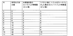
また、乱数を変更しながら符号化行列を上記のステップに従って、例えば10,000,000回程度試行していくことで、送信対象のパケット数Nに対して、符号化行列の数が最小となるような符号化方法(すなわち、フィードバック情報量が最小となる符号化方法)を探索することができる。図10は、パケット数N=1~11を送信する場合に、上記設定方法に従って、フィードバック情報量が最小となる符号化方法の数を探索した結果を示している。
図10において、例えばN=11の場合、本実施形態の通信方法で必要とする符号化行列は45個であり、各符号化行列に対して受信インデックスが対応付けられるため、フィードバック情報量(受信インデックスを表現可能なビット数)は6ビットとなる。一方、図10には、複数のパケットの各々の受信状態(ACK/NACK)(1ビット)をフィードバックする従来の方法でのフィードバック情報量についても比較のために記載してある。この従来の方法では、N=11の場合には11ビットが必要であったため、本実施形態の通信方法では大幅にフィードバック情報量が低減できていることが分かる。
以上説明したように、本実施形態の通信システム、通信方法では、基地局から送信される複数のパケットに対し、移動局における各パケットの受信結果の組合せごとに予め識別情報(受信インデックス)が対応付けられている。この識別情報が基地局へフィードバックされる。そして、移動局において新規送信時の受信成功パケットが既知であることに着目し、基地局から再送されるパケットを、移動局における新規受信時の受信成功パケットによって復号可能な符号化方法で、送信対象の複数のパケットを符号化したもの(符号化パケット)とした。移動局は、符号化パケットを新規受信時の受信成功パケットによって復号し、新規受信時の受信誤りパケットを再生する。
ここで、符号化方法を適切に設定すれば、送信対象のパケット数よりも上記識別情報(受信インデックス)の数(すなわち、符号化方法の数)を少なくでき、基地局へのフィードバック情報量が低減されることは既に述べたとおりである。
ここで、符号化方法を適切に設定すれば、送信対象のパケット数よりも上記識別情報(受信インデックス)の数(すなわち、符号化方法の数)を少なくでき、基地局へのフィードバック情報量が低減されることは既に述べたとおりである。
以上、本発明の実施形態について詳述してきたが、本発明は上記実施形態に限定されず、本発明の主旨を逸脱しない範囲において、種々の改良や変更をしてもよいのは勿論である。
BS…基地局(第1通信装置、送信装置)、11…受信機、12…制御信号抽出部、13…再送制御部、14…バッファ、15…CRC付与部、16…FEC符号化部、17…信号多重部、18…送信機
MS…移動局(第2通信装置、受信装置)、31…受信機、32…信号分離部、33…FEC復号部、34…パケット復号部、35…誤り検出部、36…バッファ、37…再送制御部、38…制御信号生成部、39…送信機
MS…移動局(第2通信装置、受信装置)、31…受信機、32…信号分離部、33…FEC復号部、34…パケット復号部、35…誤り検出部、36…バッファ、37…再送制御部、38…制御信号生成部、39…送信機
Claims (9)
- 第1通信装置から第2通信装置へ複数のパケットを送信するときの通信方法であって、
第2通信装置における各パケットの受信結果の組合せごとに予め、前記複数のパケットの数より少ない数の識別情報が対応付けられており、
前記通信方法は、
第1通信装置が、第2通信装置へ複数のパケットを新規送信する第1ステップと、
第2通信装置が、前記複数のパケットの新規受信時の受信結果に基づいて第1識別情報を特定し、前記第1識別情報を第1通信装置へ送信する第2ステップと、
第1通信装置が、前記第1識別情報に基づいて、第2通信装置における新規受信時の受信成功パケットによって復号可能な符号化方法を決定し、決定した前記符号化方法で前記複数のパケットを符号化し、符号化パケットを第2通信装置へ再送信する第3ステップと、
第2通信装置が、前記符号化パケットを新規受信時の受信成功パケットによって復号し、新規受信時の受信誤りパケットを再生する第4ステップと、
を備えた通信方法。 - 前記符号化パケットの数は、第2通信装置における新規受信時の受信誤りパケットの数と同一であって、
前記第3ステップは、
第1通信装置が、前記複数のパケットの内の単一のパケットにより、又は2以上のパケットをビット単位で加算して1個の符号化パケットを生成するとともに、前記複数のパケットの各々がいずれかの符号化パケットとなる、又はいずれかの符号化パケットを生成するときの加算対象となるようにすべての符号化パケットを生成する、
請求項1に記載された通信方法。 - 前記第4ステップは、
第2通信装置が、前記符号化パケットから新規受信時の受信成功パケットをビット単位で減算することにより、前記符号化パケットを復号するステップを含む、
請求項2に記載された通信方法。 - 第1通信装置と第2通信装置を備え、第1通信装置から第2通信装置へ複数のパケットが送信される通信システムであって、
第2通信装置における各パケットの受信結果の組合せごとに予め、前記複数のパケットの数より少ない数の識別情報が対応付けられており、
第1通信装置は、
第2通信装置へ複数のパケットを新規送信する第1送信部と、
第2通信装置から前記識別情報を受信する第1受信部と、
第2通信装置から受信する識別情報に基づき、第2通信装置における新規受信時の受信成功パケットによって復号可能な符号化方法を決定し、決定した前記符号化方法で前記複数のパケットを符号化して符号化パケットを生成するパケット符号化部と、
前記符号化パケットを第2通信装置へ再送信する第2送信部と、を有し、
第2通信装置は、
第1通信装置から複数のパケットを新規受信する第2受信部と、
前記複数のパケットの受信結果に基づいて第1識別情報を特定する情報特定部と、
前記第1識別情報を第1通信装置へ送信する第3送信部と、
第1通信装置から送信される前記符号化パケットを受信する第3受信部と、
第1通信装置から送信される前記符号化パケットを新規受信時の受信成功パケットによって復号し、新規受信時の受信誤りパケットを再生するパケット復号部と、を有する、
通信システム。 - 前記符号化パケットの数は、第2通信装置における新規受信時の受信誤りパケットの数と同一であって、
前記パケット符号化部は、前記複数のパケットの内の単一のパケットにより、又は2以上のパケットをビット単位で加算して1個の符号化パケットを生成するとともに、前記複数のパケットの各々がいずれかの符号化パケットとなる、又はいずれかの符号化パケットを生成するときの加算対象となるようにすべての符号化パケットを生成する、
請求項4に記載された通信システム。 - 前記パケット復号部は、前記符号化パケットから新規受信時の受信成功パケットをビット単位で減算することにより、前記符号化パケットを復号する
請求項5に記載された通信システム。 - 前記複数のパケットの数をN個(N:2以上の整数)、前記複数のパケットの第2通信装置における新規受信時の受信誤りパケットの数をM個(M:2以上の整数)とし、M個の符号化パケットのビット列を、N個の複数のパケットのビット列に対するM×Nの第1行列(成分が0又は1である。)で表したときに、
前記第1行列は、第1行列をM×Mの第2行列に縮退させたときに前記第2行列が逆行列を有するようにして、設定される、
請求項5又は6に記載された通信システム。 - 受信装置へ複数のパケットを送信する送信装置であって、
受信装置へ複数のパケットを新規送信する第1送信部と、
受信装置から、受信装置における各パケットの受信結果の組合せに対応する識別情報を受信する第1受信部と、
受信装置から受信する識別情報に基づき、受信装置における前記複数のパケットの新規受信時の受信成功パケットによって復号可能な符号化方法を決定し、決定した前記符号化方法で前記複数のパケットを符号化するパケット符号化部と、
前記符号化パケットを受信装置へ再送信する第2送信部と、
を備えた、送信装置。 - 送信装置から複数のパケットを受信する受信装置であって、前記複数のパケットの各パケットの受信結果の組合せごとに予め、前記複数のパケットの数より少ない数の識別情報が対応付けられており、
送信装置から複数のパケットを新規受信する第2受信部と、
前記複数のパケットの受信結果に基づいて第1識別情報を特定する情報特定部と、
前記第1識別情報を送信装置へ送信する第3送信部と、
前記第1識別情報に基づき、新規受信時の受信成功パケットによって復号可能な符号化方法で前記複数のパケットが符号化され、送信装置から送信される符号化パケット、を受信する第3受信部と、
前記符号化パケットを新規受信時の受信成功パケットによって復号し、新規受信時の受信誤りパケットを再生するパケット復号部と、
を備えた、受信装置。
Priority Applications (4)
| Application Number | Priority Date | Filing Date | Title |
|---|---|---|---|
| JP2011531642A JP5482795B2 (ja) | 2009-09-17 | 2009-09-17 | 通信方法、通信システム、送信装置、受信装置 |
| EP09849428.9A EP2479916A4 (en) | 2009-09-17 | 2009-09-17 | COMMUNICATION PROCEDURE, COMMUNICATION SYSTEM, TRANSMITTER AND RECEIVER |
| PCT/JP2009/004691 WO2011033568A1 (ja) | 2009-09-17 | 2009-09-17 | 通信方法、通信システム、送信装置、受信装置 |
| US13/412,235 US8542756B2 (en) | 2009-09-17 | 2012-03-05 | Communication method, communication system, transmission device, and receiving device |
Applications Claiming Priority (1)
| Application Number | Priority Date | Filing Date | Title |
|---|---|---|---|
| PCT/JP2009/004691 WO2011033568A1 (ja) | 2009-09-17 | 2009-09-17 | 通信方法、通信システム、送信装置、受信装置 |
Related Child Applications (1)
| Application Number | Title | Priority Date | Filing Date |
|---|---|---|---|
| US13/412,235 Continuation US8542756B2 (en) | 2009-09-17 | 2012-03-05 | Communication method, communication system, transmission device, and receiving device |
Publications (1)
| Publication Number | Publication Date |
|---|---|
| WO2011033568A1 true WO2011033568A1 (ja) | 2011-03-24 |
Family
ID=43758196
Family Applications (1)
| Application Number | Title | Priority Date | Filing Date |
|---|---|---|---|
| PCT/JP2009/004691 Ceased WO2011033568A1 (ja) | 2009-09-17 | 2009-09-17 | 通信方法、通信システム、送信装置、受信装置 |
Country Status (4)
| Country | Link |
|---|---|
| US (1) | US8542756B2 (ja) |
| EP (1) | EP2479916A4 (ja) |
| JP (1) | JP5482795B2 (ja) |
| WO (1) | WO2011033568A1 (ja) |
Families Citing this family (2)
| Publication number | Priority date | Publication date | Assignee | Title |
|---|---|---|---|---|
| JP6724583B2 (ja) * | 2016-06-15 | 2020-07-15 | 富士通株式会社 | 情報処理装置、情報処理方法、プログラム及び情報処理システム |
| KR101934638B1 (ko) * | 2017-05-12 | 2019-01-02 | 이화여자대학교 산학협력단 | 행렬 분해를 이용한 저복잡 네트워크 코딩에 기초하는 네트워크 인코딩 장치 및 방법 |
Citations (5)
| Publication number | Priority date | Publication date | Assignee | Title |
|---|---|---|---|---|
| JPH09116559A (ja) * | 1995-10-23 | 1997-05-02 | Nippon Telegr & Teleph Corp <Ntt> | 誤り回復装置 |
| JPH11136220A (ja) * | 1997-06-04 | 1999-05-21 | Toshiba Corp | 符号伝送方法、送信装置、受信装置および通信システム |
| WO2003028314A1 (fr) | 2001-09-19 | 2003-04-03 | Sharp Kabushiki Kaisha | Procede de communication, appareil de communication, apparei de reception, programme de communication, programme de communication contenant un support d'enregistrement lisible par ordinateur, et systeme de reseau |
| JP2004349891A (ja) * | 2003-05-20 | 2004-12-09 | Ntt Docomo Inc | パケット送信装置、パケット受信装置、方法及びプログラム |
| WO2006061902A1 (ja) * | 2004-12-09 | 2006-06-15 | Mitsubishi Denki Kabushiki Kaisha | データ送信装置、データ受信装置、およびデータ配信システム |
Family Cites Families (7)
| Publication number | Priority date | Publication date | Assignee | Title |
|---|---|---|---|---|
| US6516435B1 (en) | 1997-06-04 | 2003-02-04 | Kabushiki Kaisha Toshiba | Code transmission scheme for communication system using error correcting codes |
| US7986633B2 (en) * | 2004-12-27 | 2011-07-26 | Lg Electronics Inc. | Method of controlling data transmission for multimedia and broadcasting services in a broadband wireless access system |
| US20060268886A1 (en) * | 2005-05-04 | 2006-11-30 | Interdigital Technology Corporation | Wireless communication method and system for enhancing the capability of WLAN control frames |
| CN1801687B (zh) * | 2005-09-08 | 2013-08-07 | 华为技术有限公司 | 一种基于非应答机制的数据帧重传方法和系统 |
| US20090059958A1 (en) * | 2006-01-23 | 2009-03-05 | Nec Corporation | Communication method, communication system, nodes and program |
| US8300563B2 (en) * | 2006-09-29 | 2012-10-30 | Intel Corporation | Aggregated transmission in WLAN systems with FEC MPDUs |
| AU2008265134C1 (en) * | 2007-06-19 | 2014-09-25 | Beijing Xiaomi Mobile Software Co.,Ltd. | Adaptive transport format uplink signaling for data-non-associated feedback control signals |
-
2009
- 2009-09-17 WO PCT/JP2009/004691 patent/WO2011033568A1/ja not_active Ceased
- 2009-09-17 JP JP2011531642A patent/JP5482795B2/ja not_active Expired - Fee Related
- 2009-09-17 EP EP09849428.9A patent/EP2479916A4/en not_active Withdrawn
-
2012
- 2012-03-05 US US13/412,235 patent/US8542756B2/en not_active Expired - Fee Related
Patent Citations (5)
| Publication number | Priority date | Publication date | Assignee | Title |
|---|---|---|---|---|
| JPH09116559A (ja) * | 1995-10-23 | 1997-05-02 | Nippon Telegr & Teleph Corp <Ntt> | 誤り回復装置 |
| JPH11136220A (ja) * | 1997-06-04 | 1999-05-21 | Toshiba Corp | 符号伝送方法、送信装置、受信装置および通信システム |
| WO2003028314A1 (fr) | 2001-09-19 | 2003-04-03 | Sharp Kabushiki Kaisha | Procede de communication, appareil de communication, apparei de reception, programme de communication, programme de communication contenant un support d'enregistrement lisible par ordinateur, et systeme de reseau |
| JP2004349891A (ja) * | 2003-05-20 | 2004-12-09 | Ntt Docomo Inc | パケット送信装置、パケット受信装置、方法及びプログラム |
| WO2006061902A1 (ja) * | 2004-12-09 | 2006-06-15 | Mitsubishi Denki Kabushiki Kaisha | データ送信装置、データ受信装置、およびデータ配信システム |
Non-Patent Citations (1)
| Title |
|---|
| See also references of EP2479916A4 * |
Also Published As
| Publication number | Publication date |
|---|---|
| US20120163482A1 (en) | 2012-06-28 |
| JPWO2011033568A1 (ja) | 2013-02-07 |
| EP2479916A1 (en) | 2012-07-25 |
| US8542756B2 (en) | 2013-09-24 |
| EP2479916A4 (en) | 2014-12-17 |
| JP5482795B2 (ja) | 2014-05-07 |
Similar Documents
| Publication | Publication Date | Title |
|---|---|---|
| KR102534044B1 (ko) | 이동 통신 시스템에서 데이터 디코딩 방법 및 장치 | |
| CN109314611B (zh) | 用于在移动通信系统中提供不同服务的方法和设备 | |
| JP5444230B2 (ja) | Mimo無線通信システムにおける非同期式ハイブリッドarqプロセス表示 | |
| US10972228B2 (en) | Base station device, user equipment, wireless communication system, and communication method | |
| US20090313516A1 (en) | Enhanced hybrid automatic repeat request for long term evolution | |
| KR101681148B1 (ko) | 무선통신 시스템 및 그의 harq 운용 방법 | |
| US20210184797A1 (en) | Configuring puncture bundles of data for a first service in a transmission of a second service | |
| CN102754384B (zh) | 具有用于dtx和ack/nack的不对等差错保护的用两个分开的码字将harq反馈信息编码的技术 | |
| CN105934905A (zh) | 叠加编码的软数据包结合 | |
| TW200917727A (en) | Retransmission method for HARQ in MIMO systems | |
| KR20090119857A (ko) | Harq를 구현한 시스템에서 계층으로의 코드워드 매핑 | |
| WO2011019008A1 (en) | Methods, transmission point, serving base station and apparatus for coordinated multipoint transmission of information | |
| WO2011116668A1 (en) | System and method for transmitting and receiving acknowledgement information | |
| CN109964521B (zh) | 无线电信装置与方法 | |
| JP2011061671A5 (ja) | ||
| JP2011527137A (ja) | 無線通信システムにおける方法及び構成 | |
| US9960941B2 (en) | Controlling cyclic shift for demodulation reference symbols | |
| WO2014005474A1 (zh) | 一种mu-mimo导频和数据发射方法、装置及系统 | |
| CN108075862A (zh) | 一种物理上行共享信道上ack/nack检测的方法和装置 | |
| US11146365B2 (en) | Method and apparatus for controlling data retransmission in multiuser MIMO system | |
| WO2023206068A1 (en) | Method and apparatus for network coding-based harq in multiple mimo layers | |
| JP5482795B2 (ja) | 通信方法、通信システム、送信装置、受信装置 | |
| JP5995203B2 (ja) | 無線受信装置および無線受信方法 | |
| CN106301701B (zh) | 在must系统中用于完善harq进程的方法和装置 | |
| KR20170138339A (ko) | 이동 통신 시스템에서 이종 서비스 제공 방법 및 장치 |
Legal Events
| Date | Code | Title | Description |
|---|---|---|---|
| 121 | Ep: the epo has been informed by wipo that ep was designated in this application |
Ref document number: 09849428 Country of ref document: EP Kind code of ref document: A1 |
|
| WWE | Wipo information: entry into national phase |
Ref document number: 2011531642 Country of ref document: JP |
|
| WWE | Wipo information: entry into national phase |
Ref document number: 2009849428 Country of ref document: EP |
|
| NENP | Non-entry into the national phase |
Ref country code: DE |