WO2011033732A1 - 建設機械 - Google Patents
建設機械 Download PDFInfo
- Publication number
- WO2011033732A1 WO2011033732A1 PCT/JP2010/005389 JP2010005389W WO2011033732A1 WO 2011033732 A1 WO2011033732 A1 WO 2011033732A1 JP 2010005389 W JP2010005389 W JP 2010005389W WO 2011033732 A1 WO2011033732 A1 WO 2011033732A1
- Authority
- WO
- WIPO (PCT)
- Prior art keywords
- tank
- reducing agent
- liquid reducing
- construction machine
- cover
- Prior art date
- Legal status (The legal status is an assumption and is not a legal conclusion. Google has not performed a legal analysis and makes no representation as to the accuracy of the status listed.)
- Ceased
Links
Images




Classifications
-
- E—FIXED CONSTRUCTIONS
- E02—HYDRAULIC ENGINEERING; FOUNDATIONS; SOIL SHIFTING
- E02F—DREDGING; SOIL-SHIFTING
- E02F9/00—Component parts of dredgers or soil-shifting machines, not restricted to one of the kinds covered by groups E02F3/00 - E02F7/00
- E02F9/08—Superstructures; Supports for superstructures
- E02F9/0858—Arrangement of component parts installed on superstructures not otherwise provided for, e.g. electric components, fenders, air-conditioning units
- E02F9/0883—Tanks, e.g. oil tank, urea tank, fuel tank
-
- B—PERFORMING OPERATIONS; TRANSPORTING
- B60—VEHICLES IN GENERAL
- B60K—ARRANGEMENT OR MOUNTING OF PROPULSION UNITS OR OF TRANSMISSIONS IN VEHICLES; ARRANGEMENT OR MOUNTING OF PLURAL DIVERSE PRIME-MOVERS IN VEHICLES; AUXILIARY DRIVES FOR VEHICLES; INSTRUMENTATION OR DASHBOARDS FOR VEHICLES; ARRANGEMENTS IN CONNECTION WITH COOLING, AIR INTAKE, GAS EXHAUST OR FUEL SUPPLY OF PROPULSION UNITS IN VEHICLES
- B60K13/00—Arrangement in connection with combustion air intake or gas exhaust of propulsion units
- B60K13/04—Arrangement in connection with combustion air intake or gas exhaust of propulsion units concerning exhaust
-
- E—FIXED CONSTRUCTIONS
- E02—HYDRAULIC ENGINEERING; FOUNDATIONS; SOIL SHIFTING
- E02F—DREDGING; SOIL-SHIFTING
- E02F9/00—Component parts of dredgers or soil-shifting machines, not restricted to one of the kinds covered by groups E02F3/00 - E02F7/00
- E02F9/08—Superstructures; Supports for superstructures
- E02F9/0833—Improving access, e.g. for maintenance, steps for improving driver's access, handrails
-
- B—PERFORMING OPERATIONS; TRANSPORTING
- B01—PHYSICAL OR CHEMICAL PROCESSES OR APPARATUS IN GENERAL
- B01D—SEPARATION
- B01D53/00—Separation of gases or vapours; Recovering vapours of volatile solvents from gases; Chemical or biological purification of waste gases, e.g. engine exhaust gases, smoke, fumes, flue gases, aerosols
- B01D53/34—Chemical or biological purification of waste gases
- B01D53/92—Chemical or biological purification of waste gases of engine exhaust gases
- B01D53/94—Chemical or biological purification of waste gases of engine exhaust gases by catalytic processes
- B01D53/9404—Removing only nitrogen compounds
- B01D53/9409—Nitrogen oxides
- B01D53/9413—Processes characterised by a specific catalyst
- B01D53/9418—Processes characterised by a specific catalyst for removing nitrogen oxides by selective catalytic reduction [SCR] using a reducing agent in a lean exhaust gas
-
- B—PERFORMING OPERATIONS; TRANSPORTING
- B60—VEHICLES IN GENERAL
- B60K—ARRANGEMENT OR MOUNTING OF PROPULSION UNITS OR OF TRANSMISSIONS IN VEHICLES; ARRANGEMENT OR MOUNTING OF PLURAL DIVERSE PRIME-MOVERS IN VEHICLES; AUXILIARY DRIVES FOR VEHICLES; INSTRUMENTATION OR DASHBOARDS FOR VEHICLES; ARRANGEMENTS IN CONNECTION WITH COOLING, AIR INTAKE, GAS EXHAUST OR FUEL SUPPLY OF PROPULSION UNITS IN VEHICLES
- B60K15/00—Arrangement in connection with fuel supply of combustion engines or other fuel consuming energy converters, e.g. fuel cells; Mounting or construction of fuel tanks
- B60K15/03—Fuel tanks
- B60K15/063—Arrangement of tanks
-
- B—PERFORMING OPERATIONS; TRANSPORTING
- B60—VEHICLES IN GENERAL
- B60Y—INDEXING SCHEME RELATING TO ASPECTS CROSS-CUTTING VEHICLE TECHNOLOGY
- B60Y2200/00—Type of vehicle
- B60Y2200/40—Special vehicles
- B60Y2200/41—Construction vehicles, e.g. graders, excavators
- B60Y2200/412—Excavators
-
- F—MECHANICAL ENGINEERING; LIGHTING; HEATING; WEAPONS; BLASTING
- F01—MACHINES OR ENGINES IN GENERAL; ENGINE PLANTS IN GENERAL; STEAM ENGINES
- F01N—GAS-FLOW SILENCERS OR EXHAUST APPARATUS FOR MACHINES OR ENGINES IN GENERAL; GAS-FLOW SILENCERS OR EXHAUST APPARATUS FOR INTERNAL-COMBUSTION ENGINES
- F01N2610/00—Adding substances to exhaust gases
- F01N2610/14—Arrangements for the supply of substances, e.g. conduits
- F01N2610/1406—Storage means for substances, e.g. tanks or reservoirs
-
- F—MECHANICAL ENGINEERING; LIGHTING; HEATING; WEAPONS; BLASTING
- F01—MACHINES OR ENGINES IN GENERAL; ENGINE PLANTS IN GENERAL; STEAM ENGINES
- F01N—GAS-FLOW SILENCERS OR EXHAUST APPARATUS FOR MACHINES OR ENGINES IN GENERAL; GAS-FLOW SILENCERS OR EXHAUST APPARATUS FOR INTERNAL-COMBUSTION ENGINES
- F01N2610/00—Adding substances to exhaust gases
- F01N2610/14—Arrangements for the supply of substances, e.g. conduits
- F01N2610/1406—Storage means for substances, e.g. tanks or reservoirs
- F01N2610/1413—Inlet and filling arrangements therefore
-
- Y—GENERAL TAGGING OF NEW TECHNOLOGICAL DEVELOPMENTS; GENERAL TAGGING OF CROSS-SECTIONAL TECHNOLOGIES SPANNING OVER SEVERAL SECTIONS OF THE IPC; TECHNICAL SUBJECTS COVERED BY FORMER USPC CROSS-REFERENCE ART COLLECTIONS [XRACs] AND DIGESTS
- Y02—TECHNOLOGIES OR APPLICATIONS FOR MITIGATION OR ADAPTATION AGAINST CLIMATE CHANGE
- Y02A—TECHNOLOGIES FOR ADAPTATION TO CLIMATE CHANGE
- Y02A50/00—TECHNOLOGIES FOR ADAPTATION TO CLIMATE CHANGE in human health protection, e.g. against extreme weather
- Y02A50/20—Air quality improvement or preservation, e.g. vehicle emission control or emission reduction by using catalytic converters
-
- Y—GENERAL TAGGING OF NEW TECHNOLOGICAL DEVELOPMENTS; GENERAL TAGGING OF CROSS-SECTIONAL TECHNOLOGIES SPANNING OVER SEVERAL SECTIONS OF THE IPC; TECHNICAL SUBJECTS COVERED BY FORMER USPC CROSS-REFERENCE ART COLLECTIONS [XRACs] AND DIGESTS
- Y02—TECHNOLOGIES OR APPLICATIONS FOR MITIGATION OR ADAPTATION AGAINST CLIMATE CHANGE
- Y02T—CLIMATE CHANGE MITIGATION TECHNOLOGIES RELATED TO TRANSPORTATION
- Y02T10/00—Road transport of goods or passengers
- Y02T10/10—Internal combustion engine [ICE] based vehicles
- Y02T10/12—Improving ICE efficiencies
Definitions
- the present invention relates to a construction machine provided with a system for reducing and purifying nitrogen oxide (NOx) in exhaust gas using a liquid reducing agent.
- NOx nitrogen oxide
- a muffler provided with a reduction catalyst, and a liquid reducing agent tank for storing a liquid reducing agent such as urea water that promotes a reduction reaction by being supplied upstream of the reduction catalyst What is provided with these is well-known.
- the liquid reducing agent is consumed at a rate (for example, several percent of the fuel) according to the consumption of fuel, and therefore is normally replenished at the same timing as refueling. Therefore, in order to increase the replenishment efficiency of the fuel and the liquid reducing agent, the liquid reducing agent tank is preferably installed near the fuel tank.
- the liquid reductant tank is installed in an environment that is not easily affected by external heat such as solar heat, engine heat, and heat of the outside air, that is, a concealed environment. Is desirable.
- An object of the present invention includes a fuel tank that stores fuel supplied to an engine, and a liquid reducing agent tank that stores a liquid reducing agent for reducing and purifying nitrogen oxides in exhaust gas from the engine, It is an object of the present invention to provide a construction machine capable of providing a liquid reductant tank at a suitable position without significantly increasing the cost and required space while suppressing a decrease in the capacity of the fuel tank.
- the construction machine according to the present invention further includes a tank cover for covering the liquid reducing agent tank, and the upper surface of the fuel tank has a high surface and a lower surface than the high surface.
- the tank cover is provided at a position substantially the same as the high level surface above the low level surface, so that the liquid reducing agent tank installation space is provided between the low level surface and the low level surface.
- the liquid reductant tank has a replenishment port for replenishing the liquid reductant from the outside to the tank, and the liquid reductant tank installation space is in a state where the replenishment port approaches the lower surface of the tank cover. Installed.
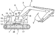
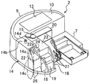
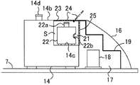
- FIG. 5 is a sectional view taken along line VV in FIG. 2. It is a perspective view of a fuel tank and a liquid reducing agent tank concerning a 2nd embodiment of the present invention. It is a perspective view of a fuel tank and a liquid reducing agent tank concerning a 3rd embodiment of the present invention.
- the construction machine according to this embodiment is an excavator.
- the present invention is not limited to the excavator, but other construction machines, for example, a dismantling machine or a crushing machine configured by adding an appropriate attachment to the main body of the excavator as a base, and a liquid reducing agent. It can be applied to various construction machines equipped with a system for reducing and purifying nitrogen oxides in exhaust gas.
- the excavator according to this embodiment turns around a crawler-type lower traveling body 1 and a vertical axis that is perpendicular to the ground.
- An upper swing body 2 that is freely mounted and a work attachment 6 attached to the front portion of the upper swing body 2 are provided.
- the work attachment 6 includes a boom 3, an arm 4, and a bucket 5.
- the upper swing body 2 includes an upper frame 7 serving as a base, a cabin 8 provided at a left front portion of the upper frame 7, and a counterweight 9 provided at a rear end portion of the upper frame 7.
- An engine room 10 located in front of the counterweight 9 is formed at the rear of the body 2.
- an engine 11 as a power source and engine peripheral devices including a hydraulic pump 12 and a heat exchanger (not shown) are installed, and the engine 11 faces in the left-right direction (in this specification, “Front / Right” and “Left / Right” indicate directions viewed from the operator seated in the cabin 8).
- a bonnet 13 is provided above the engine room 10 so as to be rotatable, that is, openable and closable with the rear end as a central axis. Maintenance of the engine 11 and the like from the upper surface side of the engine room is performed in a state where the bonnet 13 is opened.
- the fuel tank 14 and the hydraulic oil tank 15 are provided on the right side of the upper swing body 2 so as to be lined up on the left and right at a position close to the engine room 10.
- a front cover 16 (see FIGS. 1 and 5) that covers the equipment chamber 17 from above is provided in front of the tanks 14 and 15, and a control valve 18 that controls the operation of the hydraulic actuator is provided in the equipment chamber 17. . That is, in this shovel, the equipment room 17 is provided at a position away from the engine room 10, and the fuel tank 14 is disposed between the equipment room 17 and the engine room 10.
- an elevating staircase 19 that rises toward the hood 13 is formed integrally with the cover 16.
- the elevating stairs 19 allows an operator to climb up the elevating stairs 19 from the front of the machine and access the upper portion of the engine room 10 to perform opening / closing and maintenance work of the hood 13.
- an exhaust duct 20 (see FIGS. 2 and 3) is provided in front of the substantially central portion of the engine room 10. The exhaust duct 20 projects forward, discharges high-temperature air in the engine room 10 to the outside, and the upper surface of the exhaust duct 20 also serves as a scaffold during maintenance work.
- This construction machine further includes a boom foot pin 21 (see FIGS. 2 and 5).
- the boom foot pin 21 connects the base end portion of the boom 3 constituting the work attachment 6 to the upper swing body 2 in front of the exhaust duct 20, and the boom 3 is centered on the boom foot pin 21 in the connected state.
- the upper swing body 2 is provided with a boom support portion, and this boom support portion is constituted by a pair of boom support plates 27 erected so as to sandwich the base end portion of the boom 3 from both left and right sides,
- the boom foot pin 21 is connected to the boom support plate 27 and the base end portion of the boom 3 along the boom foot pin insertion / removal line corresponding to the axis O (see FIG. 2). It is inserted and removed in the axial direction, so that the boom 3 can be attached and detached.
- the upper surface of the fuel tank 14 has a high surface 14b and a low surface 14c lower than the high surface 14b, and both surfaces 14a and 14b are mutually connected via a step 14a. Adjacent.
- the high level surface 14b constitutes the top surface of the rear half of the fuel tank 14 facing the engine room 10, and the low level surface 14c is the top surface of the front half that is the front side of the rear half.
- the upper surface of the fuel tank 14 has an L-shape in which the high-order surface 14b and the low-order surface 14c are continuous stepwise in the front-rear direction via the step 14a.
- the high surface 14b is provided with a fuel filler opening 14d for refueling the fuel tank 14 from the outside.
- the construction machine further includes a tank cover 23 attached to the fuel tank 14.
- the tank cover 23 is provided above the low level surface 14c at substantially the same height position as the high level surface 14b (exactly the same height position or a position slightly shifted above or below the height position), A liquid reducing agent tank installation space S is formed between the lower surface 14c.
- the liquid reducing agent tank 22 has a replenishing port 22a (a reference numeral is attached only to FIGS. 3 to 5) for replenishing the liquid reducing agent tank 22 from outside.
- the supply port 22 a is provided on the upper surface of the liquid reducing agent tank 22.
- the liquid reductant tank 22 is located in a state where the replenishing port 22a is close to the lower surface of the tank cover 23, that is, the replenishing port 22a is lower than the refueling port 14d of the fuel tank 14 but close thereto. In the state, it is installed in the liquid reducing agent tank installation space S.
- the tank cover 23 is formed integrally with the front cover 16 to constitute a single cover member. Specifically, the tank cover 23 is connected to the top of the ascending / descending stairs 19 formed on the cover 16.
- the tank cover 23 is provided with an opening / closing lid 24. Specifically, a portion of the cover 23 located immediately above the liquid reducing agent tank 22 constitutes the opening / closing lid 24.
- the opening / closing lid 24 is attached to the other part of the tank cover 23 so as to be openable / closable, specifically, rotatable about the front end of the opening / closing lid 24, and the liquid lid with the opening / closing lid 24 open.
- a liquid reducing agent can be replenished in the reducing agent tank 22.
- this construction machine includes a heat shield plate 25 which is a heat shield member.
- the heat shield plate 25 is interposed between the liquid reducing agent tank 22 and the control valve 18 and blocks heat generated by the control valve 18 from being transmitted to the liquid reducing agent tank 22.
- the heat shield plate 25 according to this embodiment hangs down from the lower surface of the top portion of the front cover 16 and covers the liquid reducing agent tank 22 from the front side.
- the liquid reductant tank installation space S has a boom foot pin insertion / removal line corresponding to the axis O of the boom foot pin 21 extending in the width direction of the upper swing body 2. That is, a line along which the boom foot pin 21 is inserted and removed with respect to the base end portion of the boom 3 and the boom support portion (the pair of boom support members 27) passes through the liquid reducing agent tank installation space S. It is in such a position.
- a notch 22b is provided at a front portion of the liquid reducing agent tank 22 provided in the space S. The notch 22b is inserted into and removed from the liquid reducing agent tank 22 along the boom foot pin insertion / removal line O. It has a shape that prevents interference with the foot pin 21.
- An openable and closable side cover 26 (see FIGS. 1 and 3) is provided on the right side of the equipment chamber 17.
- the side cover 28 includes a front half portion of the fuel tank 14, a right side surface of the liquid reducing agent tank 22, and a control valve 18. Cover the right side of from the side.
- the upper surface of the fuel tank 14 includes the high level surface 14b and the low level surface 14c that are adjacent to each other via the step 14a, and is located above the low level surface 14c and at substantially the same height as the high level surface 14b.
- a tank cover 23 is provided to form a liquid reducing agent tank installation space S between the lower surface 14 c and the liquid reducing agent tank 22 is installed in the space S. Accordingly, the liquid reducing agent tank 22 is installed in a shielded environment that is covered from above by the tank cover 23 and is not easily affected by external heat.
- the liquid reductant tank 22 is placed directly on the lower surface 14c without using a dedicated tank stand, so that the height position of the replenishing port 22a of the liquid reductant tank 22 is the same as that of the fuel tank 14. It can be brought close to the height position of the fuel filler opening 14d. Further, since the fuel tank 14 can be left in a region below the lower surface 14c where the liquid reducing agent tank 22 is installed, for example, the fuel tank 14 is installed from the top to the bottom at the place where the liquid reducing agent 22 is installed. When cut, in other words, the volume of the fuel tank 14 can be secured more than when the fuel tank 14 is not installed at the installation location.
- the liquid reducing agent tank 22 is shielded from being not affected by external heat without requiring a dedicated tank stand for raising the volume and suppressing the reduction in the volume of the fuel tank 14. It can be installed in an environment that is easy to replenish.
- the liquid reductant tank 22 Since the upper surface of the fuel tank 14 has a shape (for example, an L shape) in which the high-order surface 14b and the low-order surface 14c are continuous in a step shape when viewed from the side, the liquid reductant tank 22 has a liquid reductant tank installation space S. Can be taken in and out in multiple directions. This facilitates taking in and out for cleaning or the like in the liquid reducing agent tank 22.
- the liquid reductant tank 22 installed on the low level surface 14c is a portion having the high level surface 14d of the fuel tank 14 as an upper surface (rear) It is located on the opposite side of the engine room 10 across the side half). Therefore, the portion having the upper surface 14d as the upper surface can suppress heat transfer from the engine room 10 to the liquid reductant tank 22, thereby suppressing the temperature increase of the liquid reductant due to heat in the engine room 10. Can contribute.
- the opening / closing lid 24 provided on the tank cover 23 is required to detach the entire tank cover 23 (in this embodiment, the entire front cover 16 integrally formed with the cover 23) in order to replenish the liquid reducing agent. Thereby facilitating replenishment of the liquid reducing agent.
- the heat shield plate 25 blocks heat transfer from the control valve 18 that controls the operation of the hydraulic actuator to the liquid reducing agent tank 22, and thereby closes the control valve 18 and the liquid reducing agent tank 22. Regardless, the temperature increase of the liquid reducing agent due to the heat generated by the control valve 18 can be suppressed.
- the tank cover 23 Since the tank cover 23 is formed integrally with the front cover 16 that covers the upper surface side of the equipment chamber 17 and constitutes a single cover member, the tank cover 23 is a dedicated member different from the front cover 16. Compared with the case where is constructed, the structure is simple, the assembly is easy, and the cost is low. In particular, since the tank cover 23 according to this embodiment is connected to the top of the elevating staircase 19 formed on the front cover 16, the tank cover 23 becomes an obstacle to elevating or the tank cover 23 and the top of the elevating staircase 19. There is no negative effect of creating a gap between them.
- a boom foot pin insertion / removal corresponding to the axis O of the boom foot pin 21, that is, a line along which the boom foot pin 21 is inserted / removed in the axial direction passes through the liquid reducing agent tank installation space S. Since there is the liquid reducing agent installation space S at a certain position, the boom foot pin 21 can be inserted and removed by a route passing through the liquid reducing agent tank installation space S. That is, since the liquid reductant tank installation space S also serves as a pin insertion / removal space for enabling the boom foot pin 21 to be inserted / removed, it is not necessary to separately secure an independent pin insertion / removal space.
- the notch 22b formed on the front surface of the liquid reducing agent tank 22 interferes with the tank 22 and the boom foot pin 21 without substantially reducing the volume of the tank 22 and without requiring movement of the tank 22. It is possible to insert and remove the foot pin 21 without any need. Since the liquid reductant tank 22 is smaller and lighter than the fuel tank 14 and can be moved relatively easily, the liquid reductant tank 22 is used as the boom foot pin 21 when the notch 22b is not provided. It is also possible to move to a position where it does not interfere with insertion and removal.
- the specific shape of the liquid reducing agent tank according to the present invention is not limited to the above.
- the shape of the liquid reducing agent tank 22 is opposite to that of the liquid reducing agent 22 according to the first embodiment.
- the shape may be such that the high level surface 14b is positioned on the front side and the low level surface 14c is positioned on the rear side. In other words, it may be L-shaped when viewed from the left side.
- the central portion in the front-rear direction of the upper surface of the liquid reducing agent tank 22 is recessed, that is, the high-order surfaces 14b, 14b are located on the front and rear sides, respectively.
- the low level surface 14c may be positioned at the center between the high level surfaces 14b and 14b, and the steps 14a and 14a may be interposed between the low level surface 14c and the high level surfaces 14b and 14b.
- the tank cover 23 is formed as an independent member separate from the front cover 16, and the liquid reducing agent tank 22 is viewed from above, or from above and from the right side as shown. What is necessary is just to provide in the state covered.
- the present invention provides an engine, a fuel tank that stores fuel supplied to the engine, and a liquid reduction that stores a liquid reducing agent for reducing and purifying nitrogen oxides in exhaust gas from the engine.
- a construction machine that can be provided with a liquid reductant tank at a suitable position without significant increase in cost and required space while including a reduction agent tank and suppressing a decrease in the capacity of the fuel tank.
- the construction machine according to the present invention further includes a tank cover for covering the liquid reducing agent tank, and the upper surface of the fuel tank is lower than the high surface and the high surface through a step.
- the tank cover is provided at substantially the same height as the high surface above the low surface, thereby forming a liquid reducing agent tank installation space between the low surface and the low surface.
- the liquid reductant tank has a replenishment port for replenishing the liquid reductant from the outside to the tank, and the liquid reductant tank installation space is in a state where the replenishment port approaches the lower surface of the tank cover. Installed.
- the liquid reductant tank can be installed in an environment that is covered with a tank cover and shielded from the outside and hardly affected by external heat. Moreover, if a liquid reductant tank is installed on the lower surface of the fuel tank, the height of the replenishing port of the liquid reductant tank is set to the height of the fuel tank refueling port without using a dedicated tank stand. You can get closer. Further, since the fuel tank can be left in the region below the lower surface, for example, when no fuel tank is provided in the installation region of the liquid reducing agent tank, that is, in the installation region, the fuel tank is placed from above. Compared with the case of cutting to the bottom, it is possible to suppress the reduction in the capacity of the fuel tank accompanying the installation of the liquid reducing agent tank.
- the liquid reductant tank is replenished in a shielded environment that is not easily affected by external heat, without using a dedicated tank stand for raising the volume and suppressing the decrease in the capacity of the fuel tank. Can be installed in an easy state.
- the specific shape of the upper surface of the fuel tank is preferably such that the high-order surface and the low-order surface are continuous in steps through a step. This shape enables the liquid reducing agent tank to be taken in and out in a plurality of directions with respect to the liquid reducing agent tank installation space on the lower surface of the fuel tank. Makes loading and unloading work easier.
- the tank cover is provided with an opening / closing lid that can be opened and closed so that the liquid reducing agent tank can be replenished from the outside of the tank cover.
- This open / close lid eliminates the need to detach the entire tank cover when replenishing the liquid reducing agent, thereby facilitating replenishment of the liquid reducing agent.
- the construction machine according to the present invention may further include a control valve that controls the operation of the hydraulic actuator.
- the control valve is provided close to the liquid reducing agent tank, so that the size of the entire construction machine can be reduced. Further, by providing a heat shield member for blocking heat transfer from the control valve to the liquid reducing agent tank between the liquid reducing agent tank and the control valve, the control valve can be used regardless of the proximity arrangement. The rise in temperature of the liquid reducing agent due to the heat generated by the can be suppressed.
- the present invention includes a lower traveling body and an upper revolving body that is rotatably mounted on the lower traveling body, and the engine, the fuel tank, and the liquid reducing agent tank are mounted on the upper revolving body. It is suitably used for construction machinery.
- an engine room for storing the engine is provided at the rear of the upper swing body, and the fuel tank is provided on either the left or right side in front of the engine room. It is preferable that the surface is located in front of the high-order surface.
- the upper part of the upper surface of the fuel tank is interposed between the liquid reductant tank and the engine room, thereby blocking heat transfer from the engine room to the liquid reductant tank. can do.
- the apparatus further includes a front cover that covers the equipment room at a position away from the engine room, and the fuel tank is provided near the engine room between the equipment room and the engine room. It is also preferable that the liquid reducing agent tank is provided between the apparatus chamber and the tank cover that covers the liquid reducing agent tank is integrated with the front cover to form a single cover member. As described above, the tank cover that covers the liquid reducing agent and the front cover that covers the equipment chamber are integrally formed, thereby reducing the number of parts of the entire construction machine, facilitating assembly work, and reducing costs.
- a bonnet that can be opened and closed above the engine room is further provided, and on the upper surface of the front cover, an elevating staircase that rises from the front end portion of the upper swing body toward the bonnet is formed, and the tank More preferably, the cover is connected to the top of the ascending / descending staircase.
- the elevating staircase and the tank cover are adjacent to each other, the tank cover hinders the operator from moving up and down the elevating staircase, or a gap is created between the tank cover and the elevating staircase. Inconvenience can be prevented.
- a work attachment including a boom mounted on the upper swing body so as to be able to undulate, and a base end portion of the boom and a boom support portion provided on the upper swing body can be rotated in the direction of the undulation.
- a boom foot pin insertion is further provided that further includes a boom foot pin that is inserted into and removed from the base end portion of the boom and the boom support portion in the axial direction so as to be connected, and that serves as a pivot for the boom in the connected state. It is preferable that the liquid reducing agent tank installation space is formed at a position where a line that is derailed and along which the boom foot pin is inserted and removed passes through the liquid reducing agent tank installation space.
- the boom foot pin is inserted and removed by a route passing through the liquid reducing agent tank installation space, that is, the liquid reducing agent tank installation space also serves as a pin insertion / removal space for inserting and removing the boom foot pin.
- the liquid reducing agent tank installation space also serves as a pin insertion / removal space for inserting and removing the boom foot pin.
- a pin insertion / removal space independent of the liquid reducing agent tank installation space is provided, more space required for the arrangement of various devices can be secured.
- the liquid reducing agent tank is small and lightweight, the tank can be easily moved when the tank interferes with pin insertion and removal.
- a notch for preventing interference between the boom foot pin to be inserted and removed and the liquid reducing agent tank may be provided in the liquid reducing agent tank.
Landscapes
- Engineering & Computer Science (AREA)
- Mining & Mineral Resources (AREA)
- Civil Engineering (AREA)
- General Engineering & Computer Science (AREA)
- Structural Engineering (AREA)
- Chemical & Material Sciences (AREA)
- Combustion & Propulsion (AREA)
- Transportation (AREA)
- Mechanical Engineering (AREA)
- Exhaust Gas After Treatment (AREA)
- Component Parts Of Construction Machinery (AREA)
- Cooling, Air Intake And Gas Exhaust, And Fuel Tank Arrangements In Propulsion Units (AREA)
- Exhaust Gas Treatment By Means Of Catalyst (AREA)
Abstract
この発明の目的は、エンジン11と、燃料タンク14と、エンジン11からの排ガスの浄化のための液体還元剤を貯留する液体還元剤タンク25とを備えるとともに、燃料タンク14の容量減少を抑えながら、コスト及び所要スペースの大幅な増加を伴うことなく液体還元剤タンク25を好適な位置に設けることが可能な建設機械を提供することにある。この建設機械は、タンクカバー23をさらに備え、前記燃料タンク14の上面は、高位面14bとこの高位面14bよりも低く当該高位面14bに段差14aを介して隣接する低位面14cとを含み、前記タンクカバー23は前記低位面14cの上方で前記高位面14bとほぼ同じ高さ位置に設けられることにより当該低位面14cとの間に液体還元剤タンク設置空間Sを形成する。前記液体還元剤タンク22は、補給口22aを有し、この補給口22aが前記タンクカバー23の下面に接近する状態で前記液体還元剤タンク設置空間Sに設置される。
Description
本発明は、液体還元剤を用いて排ガス中の窒素酸化物(NOx)を還元浄化するシステムを備えた建設機械に関するものである。
排ガス浄化システムを備えた建設機械として、還元触媒が設けられたマフラーと、前記還元触媒の上流側に供給されることにより還元反応を促進する尿素水等の液体還元剤を貯留する液体還元剤タンクとを備えたものが公知である。この建設機械において、前記液体還元剤は、燃料の消費に応じた比率(たとえば燃料の数%)で消費されるため、通常、燃料補給と同じタイミングで補給される。従って、燃料と液体還元剤の補給能率を上げるために、液体還元剤タンクは燃料タンクの近くに設置されるのが望ましい。また、液体還元剤の品質、性能は温度によって変化するため、前記液体還元剤タンクは、太陽熱やエンジン熱、外気のもつ熱といった外部熱の影響を受けにくい環境、すなわち隠蔽された環境で設置されるのが望ましい。
従来、油圧ショベル等の建設機械において、前記条件を満足する環境に液体還元剤タンクを設置するために、当該建設機械における上部旋回体のアッパーフレームに設けられる燃料タンクの近くに開閉自在な工具類収納箱を設け、この工具類収納箱内に液体還元剤タンクを配置する技術が公知である。しかし、この公知技術は次の欠点A及びBを有する。
(A)前記液体還元剤タンクの補給口が燃料タンクの給油口よりもかなり低位に位置するから、液体還元剤をポリタンク等の補給タンクから液体還元剤タンクに補給する作業が面倒となる。具体的に、前記液体還元剤タンクは、求められる容量が小さいから、燃料タンクよりも著しく小さく、高さ寸法も小さい。その一方、前記公知技術では、燃料タンクと同じ面に設置された工具類収納箱内に液体還元剤タンクが設置されるから、必然的に液体還元剤タンクの補給口は燃料タンクの給油口よりもかなり低位になる。その対策として当該液体還元剤タンクの給油口を嵩上げするために専用のタンク台を用いることはコスト及び所要スペースの著しい増加を招く。
(B)燃料タンクの容量の大幅な減少を招く。前記公知技術は、液体還元剤タンクの収容のために工具類収納箱の平面サイズの拡張を要するから、その拡張のために、限られたスペース内で同収納箱と並置される燃料タンクの平面サイズが必然的に縮減されなければならない。従って、燃料タンクの容量が大幅に減少し、これにより、連続作業が可能な時間が短くなる。
本発明の目的は、エンジンに供給される燃料を貯留する燃料タンクと、前記エンジンからの排ガス中の窒素酸化物を還元浄化するための液体還元剤を貯留する液体還元剤タンクとを備えるとともに、燃料タンクの容量減少を抑えながら、コスト及び所要スペースの大幅な増加を伴うことなく液体還元剤タンクを好適な位置に設けることが可能な建設機械を提供することにある。この目的を達成するために、本発明に係る建設機械は、前記液体還元剤タンクを覆うためのタンクカバーをさらに備え、前記燃料タンクの上面は、高位面とこの高位面よりも低く当該高位面に段差を介して隣接する低位面とを含み、前記タンクカバーは前記低位面の上方で前記高位面とほぼ同じ高さ位置に設けられることにより当該低位面との間に液体還元剤タンク設置空間を形成する。前記液体還元剤タンクは、同タンクに外部から前記液体還元剤を補給するための補給口を有し、かつ、この補給口が前記タンクカバーの下面に接近する状態で前記液体還元剤タンク設置空間に設置される。
本発明の第1の実施の形態を図1~図5に基いて以下に説明する。この実施の形態に係る建設機械はショベルである。しかし、本発明はショベルに限られず、他の建設機械、例えば、ショベルの本体部分を母体としてこれに適当なアタッチメントが付加されることにより構成される解体機や破砕機、その他、液体還元剤を用いて排ガス中の窒素酸化物を還元浄化するシステムを備えた種々の建設機械に適用されることができる。
(1)ショベルの基本構成
この実施の形態に係るショベルは、図1~図3に示すように、クローラ式の下部走行体1と、その上に地面に対して鉛直となる縦軸まわりに旋回自在に搭載される上部旋回体2と、この上部旋回体2の前部に取付けられる作業アタッチメント6とを備え、この作業アタッチメント6はブーム3、アーム4及びバケット5を備える。
この実施の形態に係るショベルは、図1~図3に示すように、クローラ式の下部走行体1と、その上に地面に対して鉛直となる縦軸まわりに旋回自在に搭載される上部旋回体2と、この上部旋回体2の前部に取付けられる作業アタッチメント6とを備え、この作業アタッチメント6はブーム3、アーム4及びバケット5を備える。
前記上部旋回体2は、ベースとなるアッパーフレーム7と、このアッパーフレーム7の左前部に設けられるキャビン8と、同アッパーフレーム7の後端部に設けられるカウンタウェイト9とを備え、当該上部旋回体2の後部には前記カウンタウェイト9の前方に位置するエンジンルーム10が形成されている。このエンジンルーム10には、動力源としてのエンジン11と、油圧ポンプ12や図示しない熱交換器等を含むエンジン周辺機器とが設置され、エンジン11が左右方向を向いている(この明細書での「前後」「左右」はキャビン8内に着座したオペレータから見た方向を示す。)。エンジンルーム10の上方にはボンネット13がその後端を中心軸として回動可能すなわち開閉自在に設けられる。このボンネット13が開いた状態でエンジンルーム上面側からのエンジン11その他に対するメンテナンスが行われる。
前記上部旋回体2の右側には、エンジンルーム10に近い位置で燃料タンク14及び作動油タンク15が左右に並ぶように設けられる。この両タンク14,15の前方に、機器室17を上から覆うフロントカバー16(図1,5参照)が設けられ、前記機器室17に、油圧アクチュエータの作動を制御するコントロールバルブ18が設けられる。すなわち、このショベルでは、前記エンジンルーム10から前方に離れた位置に機器室17が設けられ、この機器室17と前記エンジンルーム10との間に前記燃料タンク14が配置される。
前記フロントカバー16の上面には、ボンネット13に向かって先上がりとなる昇降階段19が同カバー16と一体に形成される。この昇降階段19は、作業者が機械前方からこの昇降階段19を上ってエンジンルーム10の上方にアクセスし、ボンネット13の開閉及びメンテナンス作業を行うことを可能にする。また、エンジンルーム10のほぼ中央部の前方には、排気ダクト20(図2,3参照)が設けられる。この排気ダクト20は、前向きに突出し、エンジンルーム10内の高温空気を外部に放出するとともに、その排気ダクト20の上面がメンテナンス作業時の足場を兼ねる。
この建設機械は、ブームフットピン21(図2,5参照)をさらに備える。このブームフットピン21は、前記作業アタッチメント6を構成するブーム3の基端部を排気ダクト20の前方で上部旋回体2に連結し、その連結状態で、ブーム3は当該ブームフットピン21を中心として回動するように起伏する。詳しくは、前記上部旋回体2にブーム支持部が設けられ、このブーム支持部は、前記ブーム3の基端部を左右両側から挟むように立設される一対のブーム支持板27により構成され、これらのブーム支持板27及び前記ブーム3の基端部に対して前記ブームフットピン21が、その軸心O(図2参照)に相当するブームフットピン挿脱線に沿って当該ブームフットピン21の軸方向に抜き差しされ、これによりブーム3の脱着を可能にする。
(2)液体還元剤タンク22及びその設置
前記燃料タンク14の上面は、高位面14bと、この高位面14bよりも低い低位面14cとを有し、両面14a,14bは段差14aを介して互いに隣接する。高位面14bは、燃料タンク14のうちエンジンルーム10に面する側の後側半部の上面を構成し、低位面14cは前記後側半部の前側に位置する部分である前側半部の上面を構成する。すなわち、この燃料タンク14の上面は、前記高位面14bと前記低位面14cとが段差14aを介して前後方向に階段状に連続するL字状をなす。また、前記高位面14bには、外部から燃料タンク14に給油するための給油口14dが設けられている。
前記燃料タンク14の上面は、高位面14bと、この高位面14bよりも低い低位面14cとを有し、両面14a,14bは段差14aを介して互いに隣接する。高位面14bは、燃料タンク14のうちエンジンルーム10に面する側の後側半部の上面を構成し、低位面14cは前記後側半部の前側に位置する部分である前側半部の上面を構成する。すなわち、この燃料タンク14の上面は、前記高位面14bと前記低位面14cとが段差14aを介して前後方向に階段状に連続するL字状をなす。また、前記高位面14bには、外部から燃料タンク14に給油するための給油口14dが設けられている。
さらに、この建設機械は、前記燃料タンク14に取付けられるタンクカバー23を備える。このタンクカバー23は、前記低位面14cの上方で前記高位面14bとほぼ同じ高さ位置(全く同じ高さ位置または当該高さ位置よりも僅かに上または下にずれた位置)に設けられ、当該低位面14cとの間に液体還元剤タンク設置空間Sを形成する。
前記液体還元剤タンク22は、この液体還元剤タンク22内に外部から液体還元剤を補給するための補給口22a(図3~図5のみに参照符が付されている。)を有し、この補給口22aは当該液体還元剤タンク22の上面に設けられる。当該液体還元剤タンク22は、前記補給口22aが前記タンクカバー23の下面に近接する状態、すなわち、当該補給口22aが燃料タンク14の給油口14dよりは低いがこれに近い高さに位置する状態で、前記液体還元剤タンク設置空間Sに設置される。
前記タンクカバー23は、この実施の形態では、前記フロントカバー16と一体に形成されて単一のカバー部材を構成する。詳しくは、同カバー16に形成された前記昇降階段19の頂部に前記タンクカバー23がつながる。このタンクカバー23には開閉蓋24が設けられる。詳しくは、同カバー23のうち前記液体還元剤タンク22の直上方に位置する部分が開閉蓋24を構成する。この開閉蓋24は、開閉可能、詳しくは当該開閉蓋24の前端を中心として回動可能となるように前記タンクカバー23の他の部分に取付けられ、この開閉蓋24が開いた状態で前記液体還元剤タンク22内に液体還元剤が補給されることが可能である。
さらに、この建設機械は、遮熱部材である遮熱板25を備える。この遮熱板25は、前記液体還元剤タンク22と前記コントロールバルブ18との間に介在して当該コントロールバルブ18が発する熱が液体還元剤タンク22に伝わるのを遮断する。この実施の形態に係る遮熱板25は、前記フロントカバー16の頂部の下面から垂下して前記液体還元剤タンク22をその前面側から覆う。
この実施の形態に係る液体還元剤タンク設置空間Sは、図2,5に示すように、上部旋回体2の幅方向に延びる前記ブームフットピン21の軸心Oに相当するブームフットピン挿脱線、すなわち、その線に沿って当該ブームフットピン21がブーム3の基端部及びブーム支持部(一対のブーム支持部材27)に対して抜き差しされる線が前記液体還元剤タンク設置空間Sを通るような位置にある。同空間Sに設けられる前記液体還元剤タンク22の前部には切欠22bが設けられ、この切欠22bは、当該液体還元剤タンク22と前記ブームフットピン挿脱線Oに沿って挿脱されるブームフットピン21との干渉を防ぐ形状を有する。
前記機器室17の右側には開閉自在なサイドカバー26(図1,3参照)が設けられ、このサイドカバー28は、燃料タンク14の前半部分、液体還元剤タンク22の右側面及びコントロールバルブ18の右側面を側方から覆う。
前記のように、この実施の形態では、燃料タンク14の上面が段差14aを介して互いに隣接する高位面14b及び低位面14cを含み、低位面14cの上方で高位面14bとほぼ同じ高さ位置にタンクカバー23が設けられて前記低位面14cとの間に液体還元剤タンク設置空間Sを形成し、同空間Sに液体還元剤タンク22が設置される。従って、当該液体還元剤タンク22は、前記タンクカバー23により上方から覆われて外部熱の影響を受けにくい遮蔽された環境で設置される。しかも、専用のタンク台を用いることなく、当該液体還元剤タンク22を前記低位面14c上に直接載置することで、当該液体還元剤タンク22の補給口22aの高さ位置は燃料タンク14の給油口14dの高さ位置に近づけられる。また、当該液体還元剤タンク22が設置される低位面14cよりも下側の領域には燃料タンク14を残すことができるので、例えば液体還元剤22の設置箇所で燃料タンク14が上から下までカットされる場合、換言すれば、当該設置箇所に燃料タンク14が設置されない場合に比べ、燃料タンク14の容積をより多く確保することができる。
従って、この実施の形態に係るショベルでは、嵩上げ用の専用のタンク台を要することなく、また燃料タンク14の容積の削減を抑えながら、液体還元剤タンク22が、外部熱の影響を受けない遮蔽された環境で、しかも補給が容易な状態で設置されることができる。
加えて、この実施形態では次の効果が得られる。
(i)燃料タンク14の上面が、側面からみて高位面14bと低位面14cが階段状に連続する形状(例えばL字状)をなすので、液体還元剤タンク22は液体還元剤タンク設置空間Sに対して複数の方向に出し入れされることができる。このことは、液体還元剤タンク22内の清掃等のための出し入れを容易にする。
(ii)燃料タンク14の低位面14cが高位面14bよりも前側にあるので、当該低位面14c上に設置される液体還元剤タンク22は燃料タンク14の高位面14dを上面とする部分(後側半部)を挟んでエンジンルーム10と反対の側に位置する。従って、当該高位面14dを上面とする部分はエンジンルーム10から液体還元剤タンク22への伝熱を抑止することができ、これにより、エンジンルーム10内の熱による液体還元剤の温度上昇の抑制に寄与することができる。
(iii)タンクカバー23に設けられた開閉蓋24は、液体還元剤の補給のためにタンクカバー23全体(この実施形態では同カバー23が一体に形成されたフロントカバー16全体)を脱着する必要をなくし、これにより、液体還元剤の補給を容易にする。
(iv)遮熱板25は、油圧アクチュエータの作動を制御するコントロールバルブ18から液体還元剤タンク22への伝熱を遮断し、これにより、当該コントロールバルブ18と液体還元剤タンク22との近接にかかわらず、コントロールバルブ18の発する熱による液体還元剤の温度上昇を抑えることができる。
(v)タンクカバー23は、機器室17の上面側を覆うフロントカバー16と一体に形成されて単一のカバー部材を構成するから、当該フロントカバー16とは別の専用の部材でタンクカバー23が構成される場合に比べ、構造が簡素で組立が簡単であり、コストが低い。特に、この実施の形態に係るタンクカバー23は、フロントカバー16に形成される昇降階段19の頂部につながるから、タンクカバー23が昇降の障害となったり、タンクカバー23と昇降階段19の頂部との間に隙間が生じたりする弊害がない。
(vi)ブームフットピン21の軸心Oに相当するブームフットピン挿脱線、すなわちその線に沿ってブームフットピン21が軸方向に抜き差しされる線、が液体還元剤タンク設置空間Sを通るような位置に当該液体還元剤設置空間Sがあるので、ブームフットピン21は液体還元剤タンク設置空間Sを通るルートで抜き差しされることができる。すなわち、液体還元剤タンク設置空間Sがブームフットピン21の挿脱を可能にするためのピン挿脱空間を兼ねるため、独立したピン挿脱空間を別途確保する必要がなく、その分、各機器の配置のための空間をより多く確保できる。さらに、液体還元剤タンク22の前面に形成された切欠22bは、同タンク22の容積をほとんど減らすことなく、また同タンク22の移動を要することなく、同タンク22とブームフットピン21との干渉なしに当該フットピン21を抜き差しすることを可能にする。なお、液体還元剤タンク22は燃料タンク14に比べると小型軽量で比較的簡単に移動させることができるため、前記切欠22bがない場合、液体還元剤タンク22を同タンク22がブームフットピン21の抜き差しの邪魔にならない位置まで移動させることも可能である。
本発明に係る液体還元剤タンクの具体的な形状は前記のものに限られない。例えば、本発明の第2の実施の形態として図6に示すように、液体還元剤タンク22の形状は、前記第1の実施の形態に係る液体還元剤22とは前後逆向きの形状、すなわち、前側に高位面14bが位置し、後ろ側に低位面14cが位置するような形状であってもよい。換言すれば、左側面から見てL字形となる形状であってもよい。あるいは、第3の実施の形態として図7に示すように、液体還元剤タンク22の上面のうちその前後方向の中央部が凹んだ形状、すなわち、前後両側にそれぞれ高位面14b,14bが位置し、これらの高位面14b,14bの間の中央部に低位面14cが位置し、この低位面14cと前記両高位面14b,14bとの間にそれぞれ段差14a,14aが介在する形状でもよい。これら第2及び第3の実施の形態では、タンクカバー23がフロントカバー16とは別の独立した部材として形成され、液体還元剤タンク22を上方から、または図示のように上方と右側面とから覆う状態で設けられればよい。
以上のように、本発明は、エンジンと、このエンジンに供給される燃料を貯留する燃料タンクと、前記エンジンからの排ガス中の窒素酸化物を還元浄化するための液体還元剤を貯留する液体還元剤タンクとを備えるとともに、燃料タンクの容量減少を抑えながら、コスト及び所要スペースの大幅な増加を伴うことなく液体還元剤タンクを好適な位置に設けることが可能な建設機械を提供する。具体的に、本発明に係る建設機械は、前記液体還元剤タンクを覆うためのタンクカバーをさらに備え、前記燃料タンクの上面が、高位面とこの高位面よりも低く当該高位面に段差を介して隣接する低位面とを含み、前記タンクカバーが前記低位面の上方で前記高位面とほぼ同じ高さ位置に設けられることにより当該低位面との間に液体還元剤タンク設置空間を形成する。前記液体還元剤タンクは、同タンクに外部から前記液体還元剤を補給するための補給口を有し、かつ、この補給口が前記タンクカバーの下面に接近する状態で前記液体還元剤タンク設置空間に設置される。
この建設機械において、前記液体還元剤タンクは、タンクカバーで覆われて外部から遮蔽された、外部熱の影響を受けにくい環境で設置されることができる。しかも、燃料タンクの低位面に液体還元剤タンクを設置すれば、専用のタンク台を用いなくても、当該液体還元剤タンクの補給口の高さ位置を燃料タンクの給油口の高さ位置に近づけることができる。また、前記低位面よりも下側の領域では前記燃料タンクを残すことができるので、例えば液体還元剤タンクの設置領域に全く燃料タンクを設けない場合、すなわち、当該設置領域において燃料タンクを上から下までカットする場合に比べ、前記液体還元剤タンクの設置に伴う燃料タンクの容量の削減を抑えることができる。すなわち、この建設機械では、嵩上げ用の専用のタンク台を用いることなく、また、燃料タンクの容量減少を抑えながら、液体還元剤タンクを外部熱の影響を受けにくい遮蔽された環境で、しかも補給が容易な状態で設置することができる。
前記燃料タンクの上面の具体的な形状としては、前記高位面と前記低位面とが段差を介して階段状に連続するものが、好適である。この形状は、燃料タンクの低位面上の液体還元剤タンク設置空間に対して液体還元剤タンクを複数の方向に出し入れすることを可能にし、これにより、タンク内清掃等のための液体還元剤タンクの出し入れ作業を容易にする。
前記タンクカバーには、当該タンクカバーの外側から前記液体還元剤タンクに対する液体還元剤の補給を可能にするように開閉可能な開閉蓋が設けられることが、好ましい。この開閉蓋は、液体還元剤の補給時にタンクカバー全体を脱着する必要をなくし、これにより、液体還元剤の補給を容易にする。
本発明に係る建設機械は、油圧アクチュエータの作動を制御するコントロールバルブをさらに備えてもよい。この場合、このコントロールバルブが液体還元剤タンクに近接して設けられることにより、建設機械全体の小型化を図ることができる。さらに、このコントロールバルブから液体還元剤タンクへの伝熱を遮断する遮熱部材が当該液体還元剤タンクと当該コントロールバルブとの間に設けられることにより、前記の近接配置にかかわらず、前記コントロールバルブの発する熱に起因する液体還元剤の温度上昇を抑えることができる。
本発明は、下部走行体と、この下部走行体上に旋回可能に搭載される上部旋回体とを備え、この上部旋回体に、前記エンジン、前記燃料タンク、及び前記液体還元剤タンクが搭載される建設機械に好適に使用される。このような建設機械では、前記上部旋回体の後部に前記エンジンを格納するエンジンルームが設けられ、このエンジンルームの前方の左右いずれか一方の側に前記燃料タンクが設けられ、この燃料タンクの低位面が前記高位面よりも前側に位置することが、好ましい。この建設機械では、燃料タンクのうちその上面が前記高位面である部分が、液体還元剤タンクとエンジンルームとの間に介在し、これにより、エンジンルームから液体還元剤タンクへの伝熱を遮断することができる。
また、前記エンジンルームから前方に離れた位置で機器室を覆うフロントカバーをさらに備え、当該機器室と前記エンジンルームとの間で前記エンジンルーム寄りに前記燃料タンクが設けられ、この燃料タンクと前記機器室との間に前記液体還元剤タンクが設けられ、この液体還元剤タンクを覆う前記タンクカバーが前記フロントカバーと一体となって単一のカバー部材を構成するものも、好適である。このように液体還元剤を覆うタンクカバーと機器室を覆うフロントカバーとが一体に形成されることにより、建設機械全体の部品点数が削減され、組立作業が容易になり、コストが低減する。
この場合、前記エンジンルームの上方で開閉可能に設けられるボンネットをさらに備え、前記フロントカバーの上面に、上部旋回体の前端部から前記ボンネットに向かって先上がりとなる昇降階段が形成され、前記タンクカバーがこの昇降階段の頂部につながるものが、さらに好適である。この建設機械では、昇降階段とタンクカバーとが隣接するにもかかわらず、タンクカバーが昇降階段での作業者の昇降の障害となったり当該タンクカバーと当該昇降階段との間に隙間が生じたりする不都合を防止することができる。
また、ブームを含んで前記上部旋回体に起伏可能に搭載される作業アタッチメントと、そのブームの基端部と前記上部旋回体に設けられたブーム支持部とを前記起伏の方向に回動可能に連結するように当該ブームの基端部及び当該ブーム支持部に対して軸方向に抜き差しされかつその連結状態で前記ブームの回動支点となるブームフットピンとをさらに備えたものでは、ブームフットピン挿脱線であってこれに沿って当該ブームフットピンの抜き差しが行われる線が前記液体還元剤タンク設置空間を通るような位置に当該液体還元剤タンク設置空間が形成されることが、好ましい。この建設機械では、前記ブームフットピンが液体還元剤タンク設置空間を通るルートで抜き差しされる、すなわち、液体還元剤タンク設置空間がブームフットピンの挿脱のためのピン挿脱空間を兼ねるため、前記液体還元剤タンク設置空間とは独立したピン挿脱空間を設ける場合に比べ、各種機器の配置のために必要なスペースをより多く確保することができる。この場合、液体還元剤タンクは小型軽量であるため、同タンクがピン抜き差しの邪魔になるときは同タンクを簡単に移動させることもできる。あるいは、抜き差しされる前記ブームフットピンと前記液体還元剤タンクとの干渉を防ぐための切欠が当該液体還元剤タンクに設けられてもよい。
Claims (9)
- 排ガス浄化機能を有する建設機械であって、
エンジンと、
このエンジンに供給される燃料を貯留する燃料タンクと、
前記エンジンからの排ガス中の窒素酸化物を還元浄化するための液体還元剤を貯留する液体還元剤タンクと、
前記液体還元剤タンクを覆うためのタンクカバーとを備え、
前記燃料タンクの上面は、高位面とこの高位面よりも低く当該高位面に段差を介して隣接する低位面とを含み、前記タンクカバーは前記低位面の上方で前記高位面とほぼ同じ高さ位置に設けられることにより当該低位面との間に液体還元剤タンク設置空間を形成し、前記液体還元剤タンクは、同タンクに外部から前記液体還元剤を補給するための補給口を有し、かつ、この補給口が前記タンクカバーの下面に接近する状態で前記液体還元剤タンク設置空間に設置される、建設機械。 - 請求項1記載の建設機械において、前記高位面と前記低位面とが前記段差を介して階段状に連続する、建設機械。
- 請求項1または2記載の建設機械において、前記タンクカバーに、当該タンクカバーの外側から前記液体還元剤タンクに対する液体還元剤の補給を可能にするように開閉可能な開閉蓋が設けられる、建設機械。
- 請求項1~3のいずれか1項に記載の建設機械において、前記液体還元剤タンクに近接する位置に設けられ、油圧アクチュエータの作動を制御するコントロールバルブと、このコントロールバルブと前記液体還元剤タンクとの間に設けられて当該コントロールバルブから液体還元剤タンクへの伝熱を遮断する遮熱部材とをさらに備える、建設機械。
- 請求項1~4のいずれか1項に記載の建設機械において、
下部走行体と、この下部走行体上に旋回可能に搭載される上部旋回体とを備え、この上部旋回体に、前記エンジン、前記燃料タンク、及び前記液体還元剤タンクが搭載される、建設機械。 - 請求項5記載の建設機械において、前記上部旋回体の後部に前記エンジンを格納するエンジンルームが設けられ、このエンジンルーム前方の左右いずれか一方の側に前記燃料タンクが設けられ、この燃料タンクの低位面が前記高位面よりも前側に位置する、建設機械。
- 請求項5または6記載の建設機械において、前記エンジンルームから前方に離れた位置で機器室を覆うフロントカバーをさらに備え、当該機器室と前記エンジンルームとの間で前記エンジンルーム寄りに前記燃料タンクが設けられ、この燃料タンクと前記機器室との間に前記液体還元剤タンクが設けられ、この液体還元剤タンクを覆う前記タンクカバーが前記フロントカバーと一体となって単一のカバー部材を構成する、建設機械。
- 請求項7記載の建設機械において、前記フロントカバーの上面に、上部旋回体の前端部から前記ボンネットに向かって先上がりとなる昇降階段が形成され、前記タンクカバーが前記昇降階段の頂部とつながる、建設機械。
- 請求項5~8のいずれか1項に記載の建設機械において、ブームを含んで前記上部旋回体に起伏可能に搭載される作業アタッチメントと、そのブームの基端部と前記上部旋回体に設けられたブーム支持部とを前記起伏の方向に回動可能に連結するように当該ブームの基端部及び当該ブーム支持部に対して軸方向に抜き差しされかつその連結状態で前記ブームの回動支点となるブームフットピンとをさらに備え、ブームフットピン挿脱線であってこれに沿って当該ブームフットピンの抜き差しが行われる線が前記液体還元剤タンク設置空間を通るような位置に当該液体還元剤タンク設置空間が形成される、建設機械。
Priority Applications (2)
| Application Number | Priority Date | Filing Date | Title |
|---|---|---|---|
| US13/496,709 US8661793B2 (en) | 2009-09-17 | 2010-09-01 | Construction machine |
| EP10816847.7A EP2479393B1 (en) | 2009-09-17 | 2010-09-01 | Construction machine |
Applications Claiming Priority (2)
| Application Number | Priority Date | Filing Date | Title |
|---|---|---|---|
| JP2009-215275 | 2009-09-17 | ||
| JP2009215275A JP5402451B2 (ja) | 2009-09-17 | 2009-09-17 | 建設機械 |
Publications (1)
| Publication Number | Publication Date |
|---|---|
| WO2011033732A1 true WO2011033732A1 (ja) | 2011-03-24 |
Family
ID=43758347
Family Applications (1)
| Application Number | Title | Priority Date | Filing Date |
|---|---|---|---|
| PCT/JP2010/005389 Ceased WO2011033732A1 (ja) | 2009-09-17 | 2010-09-01 | 建設機械 |
Country Status (4)
| Country | Link |
|---|---|
| US (1) | US8661793B2 (ja) |
| EP (1) | EP2479393B1 (ja) |
| JP (1) | JP5402451B2 (ja) |
| WO (1) | WO2011033732A1 (ja) |
Cited By (10)
| Publication number | Priority date | Publication date | Assignee | Title |
|---|---|---|---|---|
| WO2012172903A1 (ja) * | 2011-06-14 | 2012-12-20 | 日立建機株式会社 | 建設機械 |
| JP2015117598A (ja) * | 2013-12-17 | 2015-06-25 | ヤンマー株式会社 | 作業車両 |
| JPWO2013137169A1 (ja) * | 2012-03-16 | 2015-08-03 | 日立建機株式会社 | 建設機械 |
| JP5764725B1 (ja) * | 2014-08-08 | 2015-08-19 | 株式会社小松製作所 | 油圧ショベル |
| EP2886725A3 (en) * | 2013-12-20 | 2015-08-26 | Kobelco Construction Machinery Co., Ltd. | Construction machine |
| CN105735384A (zh) * | 2014-12-26 | 2016-07-06 | 住友建机株式会社 | 挖土机 |
| CN106978827A (zh) * | 2016-01-19 | 2017-07-25 | 住友建机株式会社 | 挖土机 |
| JP2018141360A (ja) * | 2013-10-08 | 2018-09-13 | 住友建機株式会社 | ショベル |
| JP2022046941A (ja) * | 2020-09-11 | 2022-03-24 | 株式会社小松製作所 | 装軌式搬送車両 |
| US11525241B2 (en) * | 2017-08-24 | 2022-12-13 | Caterpillar Sarl | Hydraulic shovel |
Families Citing this family (42)
| Publication number | Priority date | Publication date | Assignee | Title |
|---|---|---|---|---|
| GB0913581D0 (en) * | 2009-08-05 | 2009-09-16 | Agco Gmbh | Tractors |
| CN102781705B (zh) * | 2011-03-02 | 2014-03-12 | 株式会社小松制作所 | 储油罐以及建设车辆 |
| JP5891111B2 (ja) * | 2012-05-31 | 2016-03-22 | ヤンマー株式会社 | 作業車両 |
| US20150139768A1 (en) * | 2012-06-04 | 2015-05-21 | Hitachi Construction Machinery Co., Ltd. | Construction machine |
| ITTO20120655A1 (it) * | 2012-07-26 | 2014-01-27 | Rototech S R L | Gruppo di serbatoi, particolarmente per autoveicoli con motore diesel |
| JP5859933B2 (ja) * | 2012-08-31 | 2016-02-16 | 日立建機株式会社 | 建設機械 |
| FR2995831B1 (fr) * | 2012-09-25 | 2014-08-29 | Renault Sa | Implantation de pipe de reservoir d'uree dans un vehicule utilitaire a moteur diesel et vehicule correspondant |
| WO2014069026A1 (ja) * | 2012-10-30 | 2014-05-08 | 株式会社小松製作所 | 排気ガス後処理装置を搭載した建設車両 |
| DE202012012136U1 (de) | 2012-12-19 | 2013-01-25 | Elkamet Kunststofftechnik Gmbh | Abdeckung mit Einfüllstutzen |
| DE102012112666B3 (de) * | 2012-12-19 | 2014-03-27 | Elkamet Kunststofftechnik Gmbh | Abdeckung mit Einfüllstutzen |
| JP5336646B1 (ja) * | 2012-12-20 | 2013-11-06 | 株式会社小松製作所 | 作業車両 |
| JP5336648B1 (ja) * | 2012-12-20 | 2013-11-06 | 株式会社小松製作所 | モータグレーダ |
| CN104185725B (zh) * | 2013-03-26 | 2016-12-21 | 株式会社小松制作所 | 轮式装载机 |
| CN104185724B (zh) * | 2013-03-26 | 2017-04-05 | 株式会社小松制作所 | 轮式装载机 |
| JP5956373B2 (ja) * | 2013-03-28 | 2016-07-27 | ヤンマー株式会社 | 作業車両のエンジン装置 |
| WO2015005516A1 (ko) * | 2013-07-12 | 2015-01-15 | 볼보 컨스트럭션 이큅먼트 에이비 | 건설기계용 메인컨트롤 밸브 보호 구조 |
| JP5636511B1 (ja) * | 2013-09-25 | 2014-12-03 | 株式会社小松製作所 | 作業車両 |
| WO2015045113A1 (ja) * | 2013-09-27 | 2015-04-02 | 株式会社小松製作所 | 還元剤タンク、及び作業車両 |
| JP5867485B2 (ja) * | 2013-11-20 | 2016-02-24 | コベルコ建機株式会社 | 建設機械 |
| DE102013019448A1 (de) | 2013-11-21 | 2015-06-03 | Wirtgen Gmbh | Selbstfahrende Baumaschine |
| JP6093983B2 (ja) * | 2013-11-25 | 2017-03-15 | 日立建機株式会社 | 建設機械 |
| JP6071855B2 (ja) * | 2013-11-29 | 2017-02-01 | 日立建機株式会社 | 建設機械 |
| JP5949793B2 (ja) * | 2014-01-17 | 2016-07-13 | コベルコ建機株式会社 | 建設機械 |
| JP5949794B2 (ja) * | 2014-01-17 | 2016-07-13 | コベルコ建機株式会社 | 建設機械のツールボックス |
| JP6303717B2 (ja) | 2014-03-28 | 2018-04-04 | コベルコ建機株式会社 | 建設機械 |
| JP6218674B2 (ja) * | 2014-05-28 | 2017-10-25 | 株式会社クボタ | 作業車 |
| KR101621674B1 (ko) * | 2014-08-08 | 2016-05-16 | 가부시키가이샤 고마쓰 세이사쿠쇼 | 유압 셔블 |
| WO2015059982A1 (ja) * | 2014-08-08 | 2015-04-30 | 株式会社小松製作所 | 油圧ショベル |
| CN104428470B (zh) | 2014-08-25 | 2018-08-24 | 株式会社小松制作所 | 推土机 |
| DE202014010518U1 (de) | 2014-12-18 | 2015-11-09 | Hamm Ag | Bodenbearbeitungsmaschine, insbesondere Bodenverdichter |
| JP6005192B2 (ja) * | 2015-02-18 | 2016-10-12 | 株式会社小松製作所 | ブルドーザ |
| JP6588239B2 (ja) * | 2015-06-03 | 2019-10-09 | 日立建機株式会社 | 建設機械 |
| JP2017019470A (ja) * | 2015-07-15 | 2017-01-26 | キャタピラー エス エー アール エル | 合成樹脂製タンク |
| JP2017025743A (ja) * | 2015-07-17 | 2017-02-02 | ヤンマー株式会社 | エンジン装置 |
| US20150375616A1 (en) * | 2015-09-13 | 2015-12-31 | Caterpillar Inc. | Tank assembly for machines |
| JP6483232B2 (ja) * | 2017-12-19 | 2019-03-13 | 株式会社クボタ | 作業機 |
| JP7083278B2 (ja) * | 2018-05-29 | 2022-06-10 | 三菱マヒンドラ農機株式会社 | コンバイン |
| JP6938440B2 (ja) * | 2018-06-29 | 2021-09-22 | 株式会社クボタ | 作業機 |
| JP7166202B2 (ja) * | 2019-02-28 | 2022-11-07 | 日立建機株式会社 | 建設機械 |
| WO2022065351A1 (ja) * | 2020-09-28 | 2022-03-31 | 日立建機株式会社 | 建設機械 |
| EP4137642B1 (de) * | 2021-08-19 | 2024-03-27 | Liebherr-Werk Bischofshofen GmbH | Arbeitsmaschine |
| JP2024095469A (ja) * | 2022-12-28 | 2024-07-10 | ヤンマーホールディングス株式会社 | 建設機械 |
Citations (5)
| Publication number | Priority date | Publication date | Assignee | Title |
|---|---|---|---|---|
| JP2003020936A (ja) * | 2001-07-03 | 2003-01-24 | Komatsu Ltd | NOx還元触媒用液体還元剤タンクの配置構造 |
| JP2008240676A (ja) * | 2007-03-28 | 2008-10-09 | Komatsu Ltd | 建設車両 |
| WO2009001587A1 (ja) * | 2007-06-26 | 2008-12-31 | Hitachi Construction Machinery Co., Ltd. | 自走式建設機械 |
| JP2009062841A (ja) * | 2007-09-05 | 2009-03-26 | Toyota Motor Corp | 車両用貯液構造及び排気ガス浄化装置 |
| JP2010236208A (ja) * | 2009-03-30 | 2010-10-21 | Sumitomo (Shi) Construction Machinery Co Ltd | 建設機械 |
Family Cites Families (3)
| Publication number | Priority date | Publication date | Assignee | Title |
|---|---|---|---|---|
| JPH11131527A (ja) * | 1997-10-28 | 1999-05-18 | Hitachi Constr Mach Co Ltd | 建設機械のタンク類の設置構造 |
| JP2008240677A (ja) * | 2007-03-28 | 2008-10-09 | Komatsu Ltd | 建設車両 |
| JP2009138526A (ja) * | 2007-12-03 | 2009-06-25 | Hitachi Constr Mach Co Ltd | 建設機械 |
-
2009
- 2009-09-17 JP JP2009215275A patent/JP5402451B2/ja not_active Expired - Fee Related
-
2010
- 2010-09-01 EP EP10816847.7A patent/EP2479393B1/en not_active Not-in-force
- 2010-09-01 WO PCT/JP2010/005389 patent/WO2011033732A1/ja not_active Ceased
- 2010-09-01 US US13/496,709 patent/US8661793B2/en not_active Expired - Fee Related
Patent Citations (5)
| Publication number | Priority date | Publication date | Assignee | Title |
|---|---|---|---|---|
| JP2003020936A (ja) * | 2001-07-03 | 2003-01-24 | Komatsu Ltd | NOx還元触媒用液体還元剤タンクの配置構造 |
| JP2008240676A (ja) * | 2007-03-28 | 2008-10-09 | Komatsu Ltd | 建設車両 |
| WO2009001587A1 (ja) * | 2007-06-26 | 2008-12-31 | Hitachi Construction Machinery Co., Ltd. | 自走式建設機械 |
| JP2009062841A (ja) * | 2007-09-05 | 2009-03-26 | Toyota Motor Corp | 車両用貯液構造及び排気ガス浄化装置 |
| JP2010236208A (ja) * | 2009-03-30 | 2010-10-21 | Sumitomo (Shi) Construction Machinery Co Ltd | 建設機械 |
Cited By (20)
| Publication number | Priority date | Publication date | Assignee | Title |
|---|---|---|---|---|
| JP2013002082A (ja) * | 2011-06-14 | 2013-01-07 | Hitachi Constr Mach Co Ltd | 建設機械 |
| EP2722446A4 (en) * | 2011-06-14 | 2015-02-25 | Hitachi Construction Machinery | CONSTRUCTION MACHINE |
| US9027697B2 (en) | 2011-06-14 | 2015-05-12 | Hitachi Construction Machinery Co., Ltd. | Construction machine |
| WO2012172903A1 (ja) * | 2011-06-14 | 2012-12-20 | 日立建機株式会社 | 建設機械 |
| EP2826921A4 (en) * | 2012-03-16 | 2015-11-18 | Hitachi Construction Machinery | CONSTRUCTION MACHINE |
| JPWO2013137169A1 (ja) * | 2012-03-16 | 2015-08-03 | 日立建機株式会社 | 建設機械 |
| JP2018141360A (ja) * | 2013-10-08 | 2018-09-13 | 住友建機株式会社 | ショベル |
| JP2015117598A (ja) * | 2013-12-17 | 2015-06-25 | ヤンマー株式会社 | 作業車両 |
| EP2886725A3 (en) * | 2013-12-20 | 2015-08-26 | Kobelco Construction Machinery Co., Ltd. | Construction machine |
| US9428882B2 (en) | 2013-12-20 | 2016-08-30 | Kobelco Construction Machinery Co., Ltd. | Construction machine |
| DE112014000109B3 (de) * | 2014-08-08 | 2016-06-09 | Komatsu Ltd. | Hydraulikbagger |
| US9410306B2 (en) | 2014-08-08 | 2016-08-09 | Komatsu Ltd. | Hydraulic excavator |
| WO2016021046A1 (ja) * | 2014-08-08 | 2016-02-11 | 株式会社小松製作所 | 油圧ショベル |
| JP5764725B1 (ja) * | 2014-08-08 | 2015-08-19 | 株式会社小松製作所 | 油圧ショベル |
| CN105735384A (zh) * | 2014-12-26 | 2016-07-06 | 住友建机株式会社 | 挖土机 |
| CN106978827A (zh) * | 2016-01-19 | 2017-07-25 | 住友建机株式会社 | 挖土机 |
| CN106978827B (zh) * | 2016-01-19 | 2021-09-14 | 住友建机株式会社 | 挖土机 |
| US11525241B2 (en) * | 2017-08-24 | 2022-12-13 | Caterpillar Sarl | Hydraulic shovel |
| JP2022046941A (ja) * | 2020-09-11 | 2022-03-24 | 株式会社小松製作所 | 装軌式搬送車両 |
| JP7503977B2 (ja) | 2020-09-11 | 2024-06-21 | 株式会社小松製作所 | 装軌式搬送車両 |
Also Published As
| Publication number | Publication date |
|---|---|
| EP2479393A4 (en) | 2017-04-19 |
| JP5402451B2 (ja) | 2014-01-29 |
| US20120174566A1 (en) | 2012-07-12 |
| US8661793B2 (en) | 2014-03-04 |
| JP2011064132A (ja) | 2011-03-31 |
| EP2479393B1 (en) | 2018-06-06 |
| EP2479393A1 (en) | 2012-07-25 |
Similar Documents
| Publication | Publication Date | Title |
|---|---|---|
| WO2011033732A1 (ja) | 建設機械 | |
| JP5867485B2 (ja) | 建設機械 | |
| CN101688383B (zh) | 工程机械 | |
| EP2248695B1 (en) | Construction machine | |
| US8006991B2 (en) | Construction machine | |
| EP2256256B1 (en) | Cooling of components of a hybrid working machine | |
| US9255382B2 (en) | Construction machine | |
| CN104631539A (zh) | 工程机械 | |
| JP2011063988A (ja) | 建設機械 | |
| JP5654856B2 (ja) | 油圧ショベル | |
| JP5515551B2 (ja) | 建設機械 | |
| JP2016176291A (ja) | 小旋回型ショベル | |
| JP2011064133A (ja) | 建設機械 | |
| JP5867486B2 (ja) | 建設機械 | |
| JP6286344B2 (ja) | 建設機械 | |
| JP2004257000A (ja) | 建設機械のバッテリ取付装置及び建設機械 | |
| JP6873630B2 (ja) | 小旋回型ショベル | |
| JP4679386B2 (ja) | 旋回作業機 | |
| JP3300635B2 (ja) | 旋回式建設機械 | |
| JP2001003386A (ja) | 土木・建設機械のカバー構造 | |
| JP6156130B2 (ja) | 建設機械 | |
| JP2001323500A (ja) | 旋回作業機 |
Legal Events
| Date | Code | Title | Description |
|---|---|---|---|
| 121 | Ep: the epo has been informed by wipo that ep was designated in this application |
Ref document number: 10816847 Country of ref document: EP Kind code of ref document: A1 |
|
| WWE | Wipo information: entry into national phase |
Ref document number: 13496709 Country of ref document: US |
|
| NENP | Non-entry into the national phase |
Ref country code: DE |
|
| WWE | Wipo information: entry into national phase |
Ref document number: 2010816847 Country of ref document: EP |