WO2011034061A1 - ハイブリッド型建設機械 - Google Patents
ハイブリッド型建設機械 Download PDFInfo
- Publication number
- WO2011034061A1 WO2011034061A1 PCT/JP2010/065854 JP2010065854W WO2011034061A1 WO 2011034061 A1 WO2011034061 A1 WO 2011034061A1 JP 2010065854 W JP2010065854 W JP 2010065854W WO 2011034061 A1 WO2011034061 A1 WO 2011034061A1
- Authority
- WO
- WIPO (PCT)
- Prior art keywords
- hydraulic pump
- hydraulic
- motor
- pump
- construction machine
- Prior art date
- Legal status (The legal status is an assumption and is not a legal conclusion. Google has not performed a legal analysis and makes no representation as to the accuracy of the status listed.)
- Ceased
Links
Images


Classifications
-
- E—FIXED CONSTRUCTIONS
- E02—HYDRAULIC ENGINEERING; FOUNDATIONS; SOIL SHIFTING
- E02F—DREDGING; SOIL-SHIFTING
- E02F9/00—Component parts of dredgers or soil-shifting machines, not restricted to one of the kinds covered by groups E02F3/00 - E02F7/00
- E02F9/20—Drives; Control devices
- E02F9/22—Hydraulic or pneumatic drives
- E02F9/2278—Hydraulic circuits
- E02F9/2296—Systems with a variable displacement pump
-
- E—FIXED CONSTRUCTIONS
- E02—HYDRAULIC ENGINEERING; FOUNDATIONS; SOIL SHIFTING
- E02F—DREDGING; SOIL-SHIFTING
- E02F3/00—Dredgers; Soil-shifting machines
- E02F3/04—Dredgers; Soil-shifting machines mechanically-driven
- E02F3/28—Dredgers; Soil-shifting machines mechanically-driven with digging tools mounted on a dipper- or bucket-arm, i.e. there is either one arm or a pair of arms, e.g. dippers, buckets
- E02F3/36—Component parts
- E02F3/42—Drives for dippers, buckets, dipper-arms or bucket-arms
- E02F3/43—Control of dipper or bucket position; Control of sequence of drive operations
-
- B—PERFORMING OPERATIONS; TRANSPORTING
- B60—VEHICLES IN GENERAL
- B60K—ARRANGEMENT OR MOUNTING OF PROPULSION UNITS OR OF TRANSMISSIONS IN VEHICLES; ARRANGEMENT OR MOUNTING OF PLURAL DIVERSE PRIME-MOVERS IN VEHICLES; AUXILIARY DRIVES FOR VEHICLES; INSTRUMENTATION OR DASHBOARDS FOR VEHICLES; ARRANGEMENTS IN CONNECTION WITH COOLING, AIR INTAKE, GAS EXHAUST OR FUEL SUPPLY OF PROPULSION UNITS IN VEHICLES
- B60K6/00—Arrangement or mounting of plural diverse prime-movers for mutual or common propulsion, e.g. hybrid propulsion systems comprising electric motors and internal combustion engines
- B60K6/20—Arrangement or mounting of plural diverse prime-movers for mutual or common propulsion, e.g. hybrid propulsion systems comprising electric motors and internal combustion engines the prime-movers consisting of electric motors and internal combustion engines, e.g. HEVs
- B60K6/42—Arrangement or mounting of plural diverse prime-movers for mutual or common propulsion, e.g. hybrid propulsion systems comprising electric motors and internal combustion engines the prime-movers consisting of electric motors and internal combustion engines, e.g. HEVs characterised by the architecture of the hybrid electric vehicle
- B60K6/46—Series type
-
- E—FIXED CONSTRUCTIONS
- E02—HYDRAULIC ENGINEERING; FOUNDATIONS; SOIL SHIFTING
- E02F—DREDGING; SOIL-SHIFTING
- E02F9/00—Component parts of dredgers or soil-shifting machines, not restricted to one of the kinds covered by groups E02F3/00 - E02F7/00
- E02F9/20—Drives; Control devices
-
- E—FIXED CONSTRUCTIONS
- E02—HYDRAULIC ENGINEERING; FOUNDATIONS; SOIL SHIFTING
- E02F—DREDGING; SOIL-SHIFTING
- E02F9/00—Component parts of dredgers or soil-shifting machines, not restricted to one of the kinds covered by groups E02F3/00 - E02F7/00
- E02F9/20—Drives; Control devices
- E02F9/2058—Electric or electro-mechanical or mechanical control devices of vehicle sub-units
- E02F9/2062—Control of propulsion units
- E02F9/2075—Control of propulsion units of the hybrid type
-
- E—FIXED CONSTRUCTIONS
- E02—HYDRAULIC ENGINEERING; FOUNDATIONS; SOIL SHIFTING
- E02F—DREDGING; SOIL-SHIFTING
- E02F9/00—Component parts of dredgers or soil-shifting machines, not restricted to one of the kinds covered by groups E02F3/00 - E02F7/00
- E02F9/20—Drives; Control devices
- E02F9/22—Hydraulic or pneumatic drives
- E02F9/2221—Control of flow rate; Load sensing arrangements
- E02F9/2232—Control of flow rate; Load sensing arrangements using one or more variable displacement pumps
- E02F9/2235—Control of flow rate; Load sensing arrangements using one or more variable displacement pumps including an electronic controller
-
- E—FIXED CONSTRUCTIONS
- E02—HYDRAULIC ENGINEERING; FOUNDATIONS; SOIL SHIFTING
- E02F—DREDGING; SOIL-SHIFTING
- E02F9/00—Component parts of dredgers or soil-shifting machines, not restricted to one of the kinds covered by groups E02F3/00 - E02F7/00
- E02F9/20—Drives; Control devices
- E02F9/22—Hydraulic or pneumatic drives
- E02F9/2221—Control of flow rate; Load sensing arrangements
- E02F9/2239—Control of flow rate; Load sensing arrangements using two or more pumps with cross-assistance
- E02F9/2242—Control of flow rate; Load sensing arrangements using two or more pumps with cross-assistance including an electronic controller
-
- E—FIXED CONSTRUCTIONS
- E02—HYDRAULIC ENGINEERING; FOUNDATIONS; SOIL SHIFTING
- E02F—DREDGING; SOIL-SHIFTING
- E02F9/00—Component parts of dredgers or soil-shifting machines, not restricted to one of the kinds covered by groups E02F3/00 - E02F7/00
- E02F9/20—Drives; Control devices
- E02F9/22—Hydraulic or pneumatic drives
- E02F9/2278—Hydraulic circuits
- E02F9/2282—Systems using center bypass type changeover valves
-
- E—FIXED CONSTRUCTIONS
- E02—HYDRAULIC ENGINEERING; FOUNDATIONS; SOIL SHIFTING
- E02F—DREDGING; SOIL-SHIFTING
- E02F9/00—Component parts of dredgers or soil-shifting machines, not restricted to one of the kinds covered by groups E02F3/00 - E02F7/00
- E02F9/20—Drives; Control devices
- E02F9/22—Hydraulic or pneumatic drives
- E02F9/2278—Hydraulic circuits
- E02F9/2292—Systems with two or more pumps
-
- Y—GENERAL TAGGING OF NEW TECHNOLOGICAL DEVELOPMENTS; GENERAL TAGGING OF CROSS-SECTIONAL TECHNOLOGIES SPANNING OVER SEVERAL SECTIONS OF THE IPC; TECHNICAL SUBJECTS COVERED BY FORMER USPC CROSS-REFERENCE ART COLLECTIONS [XRACs] AND DIGESTS
- Y02—TECHNOLOGIES OR APPLICATIONS FOR MITIGATION OR ADAPTATION AGAINST CLIMATE CHANGE
- Y02T—CLIMATE CHANGE MITIGATION TECHNOLOGIES RELATED TO TRANSPORTATION
- Y02T10/00—Road transport of goods or passengers
- Y02T10/60—Other road transportation technologies with climate change mitigation effect
- Y02T10/62—Hybrid vehicles
Definitions
- the present invention relates to a hybrid construction machine in which a part of a drive mechanism is motorized.
- the first pump mainly supplies the fluid in the tank to the boom cylinder circuit that controls the boom cylinder
- the second pump mainly supplies the fluid in the tank to the arm cylinder circuit that controls the arm cylinder
- the third pump The pump has a fluid pressure motor function to supply the fluid in the tank to a swing motor circuit that controls the swing motor.
- a pressure fluid supply circuit for supplying pressure fluid to the boom cylinder circuit and the arm cylinder circuit is connected to the discharge port of the third pump.
- the present invention aims to provide a hybrid construction machine in which two pumps are arranged in an efficient manner.
- an engine a power storage device, first and second pumps, a motor for driving the first pump, and a plurality of actuators driven by the first and second pumps are provided.
- a hybrid type construction machine having The first and second pumps are arranged to control at least one each of the plurality of actuators independently of each other, The first pump is electrically driven by the motor using electric power from the power storage device, A hybrid type construction machine is provided, wherein the second pump is directly connected to the engine.
- a hybrid construction machine is obtained in which two pumps are arranged in an efficient manner.
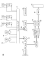
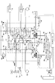
- FIG. 1 is a block diagram showing an essential part of a hydraulic system configuration according to a first embodiment.
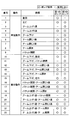
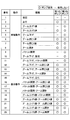
- FIG. 6 is a table showing the relationship between various operations of the hybrid construction machine 100 and the hydraulic pump used in the construction in the first embodiment.
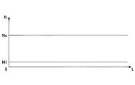
- 5 is a graph showing an example of a time series of the relationship between the engine rotation speed of the engine 11 and the rotation speed of the first hydraulic pump 28.
- FIG. FIG. 7 is a block diagram showing an essential part of a hydraulic system configuration according to a second embodiment.
- FIG. 13 is a table showing the relationship between various operations of the hybrid type construction machine 100 and a hydraulic pump used in that case in the second embodiment.
- FIG. 13 is a block diagram showing the main parts of a hydraulic system configuration according to a third embodiment.
- FIG. 14 is a table showing the relationship between various operations of the hybrid type construction machine 100 in Example 3 and hydraulic pumps used at that time.
- FIG. 1 is a main part configuration diagram showing a characteristic configuration of a hybrid type construction machine 100 according to the present invention.
- the hybrid-type construction machine 100 may be any type including a hydraulic shovel, a lifting magnet (ref mug) and the like.
- the mechanical power system is indicated by a double line
- the hydraulic line is indicated by a solid line
- the electric drive system is indicated by a thick line.
- the hybrid type construction machine 100 includes an engine 11 formed of an internal combustion engine.
- a motor generator (M / G) 12 is mechanically connected directly to the engine 11.
- a variable displacement hydraulic pump 14 (hereinafter, referred to as a second hydraulic pump 14) is mechanically connected to the rotation shaft of the motor generator 12.
- the second hydraulic pump 14 is, for example, a variable swash plate type hydraulic pump, and the pump output can be changed by changing the angle of the swash plate. That is, the angle of the swash plate can be adjusted by changing the control current supplied to the second hydraulic pump 14, whereby the output of the second hydraulic pump 14 can be changed.
- the second hydraulic pump 14 is driven by the output of the engine 11 and / or the motor generator 12 to discharge high-pressure hydraulic oil.
- the engine 11 and the motor generator 12 may be connected to a splitter (power distribution mechanism) to transmit power to the second hydraulic pump 14 via the splitter.
- the motor generator 12 is electrically connected to the battery unit 19 via an inverter 18.
- Battery unit 19 includes a converter 19A and a battery 19B.
- the battery 19B may be any battery as long as it is a secondary battery, and may be, for example, a lead battery, a nickel hydrogen battery, a lithium ion battery, or an electric double layer capacitor.
- the inverter 18 is controlled by the controller 30.
- the swing motor 21 is electrically connected to the battery unit 19 via the inverter 20.
- a swing mechanism 24 for swinging the upper swing body of the hybrid type construction machine 100 is connected to the output shaft of the swing motor 21.
- the turning mechanism 24 is driven by the power from the battery unit 19.
- the inverter 20 is controlled by the controller 30 based on the operation mode of the turning operation lever.
- a first hydraulic pump 28 instead of the swing motor 21 (see FIG. 1) electrically driven by the battery unit 19 and the inverter 20, a first hydraulic pump 28 (or The swing motor 21 driven by the hydraulic pressure generated by the hydraulic pump 14) may be used.
- a motor generator (M / G) 27 is electrically connected to the battery unit 19 via an inverter 25.
- a variable displacement hydraulic pump 28 (hereinafter, referred to as a first hydraulic pump 28) is mechanically connected to the output shaft of the motor generator 27.
- the inverter 25 is controlled by the controller 30.
- the first hydraulic pump 28 is, for example, a variable swash plate type hydraulic pump, and the pump output can be changed by changing the angle of the swash plate. That is, it is possible to adjust the angle of the swash plate by changing the control current to the first hydraulic pump 28, thereby changing the output of the first hydraulic pump 28.
- the first hydraulic pump 28 is driven by the power from the battery unit 19. That is, the first hydraulic pump 28 is driven by the output of the motor generator 27 and discharges high-pressure hydraulic oil.
- the first hydraulic pump 28 and the second hydraulic pump 14 are connected in a hydraulic circuit to various actuators associated with each other via the control valve 17.
- the various actuators include a traveling right motor 1A for driving the right wheel of the hybrid construction machine 100, a traveling left motor 1B for driving the left wheel, and a boom for driving the boom up and down.
- the first hydraulic pump 28 and the second hydraulic pump 14 have at least one of the various hydraulic actuators 1A, 1B, 7, 8 and 9 independent of each other. Are arranged to control. That is, at least one dedicated hydraulic actuator to be driven is assigned to each of the first hydraulic pump 28 and the second hydraulic pump 14.
- the kind of hydraulic actuator for exclusive use of which each is allocated to the 1st hydraulic pump 28 and the 2nd hydraulic pump 14 is arbitrary, for example, the 1st hydraulic pump 28 runs the traveling left motor 1B.
- the second hydraulic pump 14 are configured to control the traveling right motor 1A independently of the first hydraulic pump 28.
- the traveling right motor 1A can be communicated with the first hydraulic pump 28 via the switching valve
- the traveling left motor 1B can be communicated with the second hydraulic pump 14 via the switching valve. It is also good.
- the hydraulic pump for driving the actuator connected to the engine 11 and the motor generator 12 is only the second hydraulic pump 14. That is, only one second hydraulic pump 14 is connected to the engine 11 and the motor generator 12 for driving the actuator. In other words, generally, two hydraulic pumps are directly connected to the engine 11 and the motor generator 12 for driving an actuator, but one of the two hydraulic pumps is a second hydraulic pump. While remaining as the hydraulic pump 14, the other hydraulic pump is eliminated, and instead, it is driven by the motor generator 27 (a motor generator different from the motor generator 12) using the electric power from the battery unit 19.
- An actuator driving hydraulic pump (first hydraulic pump 28) is set. Note that another hydraulic pump that is not for driving the actuator, for example, a pilot pump that generates a pilot pressure necessary for a hydraulic control system may be connected to the engine 11 and the motor generator 12.
- the actuator connected to the engine 11 and the motor generator 12 only one hydraulic pump for driving the actuator connected to the engine 11 and the motor generator 12 is provided. Therefore, the actuator connected to the engine 11 and the motor generator 12 The idling pump loss can be reduced to half or less as compared with a general configuration in which there are two or more driving hydraulic pumps. Further, instead of using only one hydraulic pump for driving the actuator connected to the engine 11 and the motor generator 12, the motor generator 27 (separate from the motor generator 12) using electric power from the battery unit 19 is used. Since the actuator drive hydraulic pump (first hydraulic pump 28) driven by the motor generator is set, it is possible to supply necessary hydraulic pressure and flow rate to various actuators 1A, 1B, 7, 8 and 9. At the same time, waste of output can be eliminated.
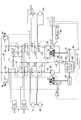
- FIG. 2 is a block diagram showing the main part of the hydraulic system configuration according to the first embodiment.
- the same reference numerals as in FIG. 1 denote the same parts in FIG.
- the mechanical power system is indicated by a double line
- the hydraulic line is indicated by a solid line
- the electric system is indicated by a thick line
- the control system is indicated by a broken line.
- the control valve 17 includes a plurality of switching valves 171-178.
- the plurality of switching valves 171-178 are a collection of switching valves 171-174 provided in the first oil passage 42 connecting the discharge side of the first hydraulic pump 28 and the reservoir tank 40, and the discharge side of the second hydraulic pump 14. And a set of switching valves 175-178 provided in the second oil passage 44 connecting the reservoir tank 40.
- the switching valves 171-174 switch the supply state of hydraulic oil for realizing the traveling operation by the traveling left motor 1B, and switch the supply state of hydraulic oil for realizing the turning operation by the turning motor 21.
- Switching valves 175-178 respectively switch the supply state of the hydraulic oil for realizing the traveling operation by the traveling right motor 1A, and the supply state of the hydraulic oil for realizing the bucket opening / closing operation by the bucket cylinder 9
- a switching valve 176 for switching, a switching valve 177 for switching the supply state of hydraulic oil to realize boom raising / lowering operation (first gear) by the boom cylinder 7, and an arm opening / closing operation (second gear) by the arm cylinder 8 are realized.
- Switching valve 178 for switching the supply state of the operating oil.
- a negative control throttle 46 throttle for negative feedback
- a negative control pressure negative control throttle
- the pressure on the upstream side of 46) Pn1 is negatively fed back to the regulator 54.
- a variable relief valve 50 that adjusts the relief pressure of the first oil passage 42 is connected to the first oil passage 42.
- the controller 30 and the regulator 54 control the first hydraulic pump 28 in a manner to reduce the loss of the discharge flow rate of the first hydraulic pump 28 returning to the reservoir tank 40 based on the negative control pressure Pn1 (so-called negative control). Do).
- a negative control throttle 48 throttle for negative feedback
- Pn2 pressure on the upstream side of the negative control throttle 48
- a variable relief valve 52 that adjusts the relief pressure of the second oil passage 44 is connected to the second oil passage 44.
- the controller 30 and the regulator 56 control the second hydraulic pump 14 in a manner to reduce the loss of the discharge flow rate of the second hydraulic pump 14 returning to the reservoir tank 40 based on the negative control pressure Pn2 (so-called negative control). Do).
- the first hydraulic pump 28 and the second hydraulic pump 14 are mechanically separated.
- a relief valve 60 for limiting the maximum pressure of the hydraulic circuit is connected to the first oil passage 42 and the second oil passage 44.
- the relief valve 60 is actuated when the pressure in the hydraulic circuit exceeds a predetermined set pressure, and brings the hydraulic circuit into communication with the reservoir tank 62.
- FIG. 3 is a table showing the relationship between various operations of the hybrid construction machine 100 and the hydraulic pump used at that time in the first embodiment.
- the first hydraulic pump 28 and the second hydraulic pump 14 include at least one of various hydraulic actuators 1A, 1B, 7, 8, 9 and 21. , Are arranged to control independently of each other.
- the first hydraulic pump 28 is configured to control the traveling left motor 1B and the swing motor 21 independently from the second hydraulic pump 14, and the second hydraulic pump 14 is controlled to travel right
- the motor 1A and the bucket cylinder 9 are configured to be controlled independently of the first hydraulic pump 28.
- the traveling right motor 1A can be communicated with the first hydraulic pump 28 via the switching valve (not shown), and the second hydraulic pump 14 via the switching valve (not shown)
- the traveling left motor 1B may be in communication.
- the hydraulic pump for driving the actuator connected to the engine 11 and the motor generator 12 is only the second hydraulic pump 14. That is, only one second hydraulic pump 14 is connected to the engine 11 and the motor generator 12 for driving the actuator.
- only one hydraulic pump for driving the actuator connected to the engine 11 and the motor generator 12 is connected to the engine 11 and the motor generator 12.
- the pump loss at idling can be reduced to half or less.
- the motor generator 27 (separate from the motor generator 12) using electric power from the battery unit 19 is used. Since the actuator drive hydraulic pump (first hydraulic pump 28) driven by the motor generator is set, the necessary hydraulic pressure and flow rate are supplied to the various actuators 1A, 1B, 7, 8, 9 and 21. While making it possible, waste of output can be saved. Specifically, as shown in FIG.
- both the first hydraulic pump 28 and the second hydraulic pump 14 are operated, and the boom cylinder 7 is operated. It can supply necessary and sufficient hydraulic pressure and flow rate.
- the second hydraulic pump 14 operates to supply the hydraulic cylinder 12 with the necessary and sufficient hydraulic pressure and flow rate. By stopping it, energy loss can be reduced. For example, as shown conceptually in FIG.
- the case where the rotational motion of the first hydraulic pump 28 continues is described, but since the first hydraulic pump 28 is not coupled to the engine 11, the rotational motion of the motor generator 27 is It can also be stopped. In this case, the rotational movement of the first hydraulic pump 28 can also be stopped, so energy loss can be further reduced.
- the motor generator 27 does not necessarily have to have a power generation function, and may be realized by an electric motor.
- FIG. 5 is a block diagram showing an essential part of a hydraulic system configuration according to a second embodiment.
- the same reference numerals as in FIG. 1 denote the same parts in FIG.
- the mechanical power system is indicated by a double line, the hydraulic line by a solid line, the electric system by a thick line, and the control system by a broken line.
- a swing motor 21 electrically driven by the battery unit 19 and the inverter 20 is used as in the configuration described with reference to FIG. 1.
- the swing motor 21 is electrically connected to the battery unit 19 via the inverter 20.
- a swing mechanism 24 for swinging the upper swing body of the hybrid type construction machine 100 is connected to the output shaft of the swing motor 21.
- the turning mechanism 24 is driven by the power from the battery unit 19.
- the inverter 20 is controlled by the controller 30 based on the operation mode of the turning operation lever.
- the swing motor 21 is a motor capable of both powering operation and regenerative operation, and is PWM (Pulse Width Modulation) driven by the above-described inverter 20.
- the swing motor 21 is preferably an IPM motor with magnets embedded inside the rotor.
- the rotational force of the rotational drive force of the rotational motor 21 is amplified by the rotational mechanism 24, and the upper structure of the hybrid construction machine 100 is controlled to accelerate and decelerate to perform rotational movement. Further, due to the inertial rotation of the upper structure of the hybrid type construction machine 100, the rotation speed is increased by the rotation mechanism 24, transmitted to the rotation motor 21, and the regenerative electric power can be generated.
- the control valve 17 includes a plurality of switching valves 171-178. However, along with the motorization of the swing motor 21, the switching valve 172 for the swing motor 21 used in the above-described first embodiment is omitted.
- the plurality of switching valves 171-178 are a collection of switching valves 171-174 provided in the first oil passage 42 connecting the discharge side of the first hydraulic pump 28 and the reservoir tank 40, and the discharge side of the second hydraulic pump 14. And a set of switching valves 175-178 provided in the second oil passage 44 connecting the reservoir tank 40.
- the switching valves 171-174 respectively switch the supply state of the hydraulic oil for realizing the traveling operation by the traveling left motor 1B, and supply of the hydraulic oil for realizing the boom raising second speed operation by the boom cylinder 7
- the switching valve 173 switches the state, and the switching valve 174 switches the supply state of the hydraulic oil for realizing the arm opening / closing operation (first gear) by the arm cylinder 8.
- Switching valves 175-178 respectively switch the supply state of the hydraulic oil for realizing the traveling operation by the traveling right motor 1A, and the supply state of the hydraulic oil for realizing the bucket opening / closing operation by the bucket cylinder 9
- a switching valve 176 for switching, a switching valve 177 for switching the supply state of hydraulic oil to realize boom raising / lowering operation (first gear) by the boom cylinder 7, and an arm opening / closing operation (second gear) by the arm cylinder 8 are realized.
- Switching valve 178 for switching the supply state of the operating oil.
- a negative control throttle 46 throttle for negative feedback
- a negative control pressure negative control throttle
- the pressure on the upstream side of 46) Pn1 is negatively fed back to the regulator 54.
- a variable relief valve 50 that adjusts the relief pressure of the first oil passage 42 is connected to the first oil passage 42.
- the controller 30 and the regulator 54 control the first hydraulic pump 28 in a manner to reduce the loss of the discharge flow rate of the first hydraulic pump 28 returning to the reservoir tank 40 based on the negative control pressure Pn1 (so-called negative control). Do).
- a negative control throttle 48 throttle for negative feedback
- Pn2 pressure on the upstream side of the negative control throttle 48
- a variable relief valve 52 that adjusts the relief pressure of the second oil passage 44 is connected to the second oil passage 44.
- the controller 30 and the regulator 56 control the second hydraulic pump 14 in a manner to reduce the loss of the discharge flow rate of the second hydraulic pump 14 returning to the reservoir tank 40 based on the negative control pressure Pn2 (so-called negative control). Do).
- the first hydraulic pump 28 and the second hydraulic pump 14 are mechanically separated.
- a relief valve 60 for limiting the maximum pressure of the hydraulic circuit is connected to the first oil passage 42 and the second oil passage 44.
- the relief valve 60 is actuated when the pressure in the hydraulic circuit exceeds a predetermined set pressure, and brings the hydraulic circuit into communication with the reservoir tank 62.
- FIG. 6 is a table showing the relationship between various operations of the hybrid construction machine 100 in the second embodiment and the hydraulic pump used at that time.
- the first hydraulic pump 28 and the second hydraulic pump 14 are made inoperable along with the motorization of the swing motor 21.
- the swing operation is realized by the swing motor 21 driven by the electric power from the battery unit 19.
- the boom raising operation (first gear) alone only the second hydraulic pump 14 is used, and the first hydraulic pump 28 is inactivated.
- the boom lowering operation alone only the second hydraulic pump 14 is used, and the first hydraulic pump 28 is inactivated.
- the first hydraulic pump 28 is inactivated.
- the first hydraulic pump 28 and the second hydraulic pump 14 are configured to transmit at least one of the various hydraulic actuators 1A, 1B, 7, 8 and 9 to each other. It is arranged to control independently.
- the first hydraulic pump 28 is configured to control the traveling left motor 1B independently from the second hydraulic pump 14, and the second hydraulic pump 14 is configured to control the traveling right motor 1A and the bucket
- the cylinder 9 is configured to be controlled independently of the first hydraulic pump 28.
- the traveling right motor 1A can be communicated with the first hydraulic pump 28 via the switching valve (not shown), and the second hydraulic pump 14 via the switching valve (not shown)
- the traveling left motor 1B may be in communication.
- the hydraulic pump for driving the actuator connected to the engine 11 and the motor generator 12 is only the second hydraulic pump 14. That is, only one second hydraulic pump 14 is connected to the engine 11 and the motor generator 12 for driving the actuator.
- the pump loss at idling can be reduced to half or less.
- the motor generator 27 (separate from the motor generator 12) using electric power from the battery unit 19 is used. Since the actuator drive hydraulic pump (first hydraulic pump 28) driven by the motor generator is set, it is possible to supply necessary hydraulic pressure and flow rate to various actuators 1A, 1B, 7, 8 and 9. At the same time, waste of output can be eliminated. Specifically, as shown in FIG.
- both the first hydraulic pump 28 and the second hydraulic pump 14 are operated, and the boom cylinder 7 is operated. It can supply necessary and sufficient hydraulic pressure and flow rate.
- the second hydraulic pump 14 operates to supply the hydraulic cylinder 12 with the necessary and sufficient hydraulic pressure and flow rate. By stopping it, energy loss can be reduced.
- the turning operation is frequently performed depending on the work content. For this reason, when performing only the turning operation, the first hydraulic pump 28 can be inactivated. Furthermore, the rotational operation itself of the first hydraulic pump 28 can also be stopped. Therefore, energy loss can be reduced because it is not necessary to flow the hydraulic oil in vain.
- the motor generator 27 does not necessarily have to have a power generation function, and may be realized by an electric motor.
- FIG. 7 is a block diagram showing an essential part of a hydraulic system configuration according to a third embodiment.
- the same reference numerals as in FIG. 1 denote the same parts in FIG.
- the mechanical power system is indicated by a double line
- the hydraulic line is indicated by a solid line
- the electric system is indicated by a thick line
- the control system is indicated by a broken line.
- a swing motor 21 electrically driven by the battery unit 19 and the inverter 20 is used as in the configuration described with reference to FIG. 1.
- the control valve 17 includes a plurality of switching valves 171-178. However, along with the motorization of the swing motor 21, the switching valve 172 for the swing motor 21 used in the above-described first embodiment is omitted.
- the plurality of switching valves 171-178 are a collection of switching valves 171-174 provided in the first oil passage 42 connecting the discharge side of the first hydraulic pump 28 and the reservoir tank 40, and the discharge side of the second hydraulic pump 14. And a set of switching valves 175-178 provided in the second oil passage 44 connecting the reservoir tank 40.
- the switching valves 171-174 respectively switch the supply state of the hydraulic oil for realizing the traveling operation by the traveling left motor 1B, and supply of the hydraulic oil for realizing the boom raising second speed operation by the boom cylinder 7
- the switching valve 173 switches the state, and the switching valve 174 switches the supply state of the hydraulic oil for realizing the arm opening / closing operation (second speed) by the arm cylinder 8.
- Switching valves 175-178 respectively switch the supply state of the hydraulic oil for realizing the traveling operation by the traveling right motor 1A, and the supply state of the hydraulic oil for realizing the bucket opening / closing operation by the bucket cylinder 9
- a switching valve 176 for switching, a switching valve 177 for switching a hydraulic oil supply state for realizing boom raising / lowering operation (first gear) by the boom cylinder 7, and an arm opening / closing operation (first gear) by the arm cylinder 8 are realized.
- Switching valve 178 for switching the supply state of the operating oil.
- a negative control throttle 46 throttle for negative feedback
- a negative control pressure negative control throttle
- the pressure on the upstream side of 46) Pn1 is negatively fed back to the regulator 54.
- a variable relief valve 50 that adjusts the relief pressure of the first oil passage 42 is connected to the first oil passage 42.
- the controller 30 and the regulator 54 control the first hydraulic pump 28 in a manner to reduce the loss of the discharge flow rate of the first hydraulic pump 28 returning to the reservoir tank 40 based on the negative control pressure Pn1 (so-called negative control). Do).
- a negative control throttle 48 throttle for negative feedback
- Pn2 pressure on the upstream side of the negative control throttle 48
- a variable relief valve 52 that adjusts the relief pressure of the second oil passage 44 is connected to the second oil passage 44.
- the controller 30 and the regulator 56 control the second hydraulic pump 14 in a manner to reduce the loss of the discharge flow rate of the second hydraulic pump 14 returning to the reservoir tank 40 based on the negative control pressure Pn2 (so-called negative control). Do).
- the first hydraulic pump 28 and the second hydraulic pump 14 are mechanically separated.
- a relief valve 60 for limiting the maximum pressure of the hydraulic circuit is connected to the first oil passage 42 and the second oil passage 44.
- the relief valve 60 is actuated when the pressure in the hydraulic circuit exceeds a predetermined set pressure, and brings the hydraulic circuit into communication with the reservoir tank 62.
- the first hydraulic pump 28 has a pump motor specification, and can cooperate with the motor generator 27 to regenerate energy. Specifically, when functioning as a motor, return oil from the head chamber 7a of the boom cylinder 7 flows in, and when discharging to the tank 62, the first hydraulic pump 28 is rotated by the return oil. By this rotation, the motor generator 27 is rotated to perform regenerative operation.
- a regeneration circuit 64 is provided between the first hydraulic operation switching valve 177 of the boom cylinder 7 and the first hydraulic pump 28. The regeneration circuit 64 brings the head chamber 7 a of the boom cylinder 7 into communication with the first hydraulic pump 28 in accordance with the position of the switching valve 177.
- the regeneration circuit 64 is provided with a flow control valve 66 controlled by the controller 30 and a check valve 68.
- the port 28a of the first hydraulic pump 28 is a discharge inflow port. Even when the first hydraulic pump 28 sucks in hydraulic oil from the tank 62 as a pump and discharges it to the respective drive units, it flows in the return oil from the head chamber 7 a of the boom cylinder 7 as a motor and discharges it to the tank 62. Even if it is, the same rotation direction is maintained. Therefore, even if the discharge direction is switched, the functions of the pump and the motor can be switched smoothly.
- the flow of the hydraulic fluid in the hydraulic circuit including the regeneration circuit 64 at the time of the boom lowering operation is indicated by arrows r1 to r12.
- the hydraulic oil discharged from the first hydraulic pump 28 is supplied to the rod chamber 7b of the boom cylinder 7 via the switching valve 177, as shown by arrows r1 to r6.
- the hydraulic fluid discharged from the head chamber 7a of the boom cylinder 7 is supplied to the first hydraulic pump 28 through the regeneration circuit 64 via the switching valve 177 as shown by arrows r7 to r12. .
- the first hydraulic pump 28 causes the motor generator 27 to perform a regenerative operation, whereby a regenerative operation is realized.
- the regenerative energy (electrical energy) obtained at this time is used to charge the battery 19 B of the battery unit 19 via the inverter 25. Then, it can be supplied to the swing motor 21 through the inverter 20 or to the motor generator 12 through the inverter 18.
- FIG. 8 is a table showing the relationship between various operations of the hybrid construction machine 100 in the third embodiment and the hydraulic pump used at that time.
- the first hydraulic pump 28 and the second hydraulic pump 14 are inactivated as the swing motor 21 is motorized.
- the swing operation is realized by the swing motor 21 driven by the electric power from the battery unit 19.
- the boom raising operation (first gear) alone only the second hydraulic pump 14 is used, and the first hydraulic pump 28 is inactivated.
- the boom lowering operation alone only the second hydraulic pump 14 is used, and the first hydraulic pump 28 realizes the above-described regenerative operation.
- the second hydraulic pump 14 is used, and the first hydraulic pump 28 is inactivated.
- the first hydraulic pump 28 and the second hydraulic pump 14 are configured to be different from each other in at least one of the various hydraulic actuators 1A, 1B, 7, 8 and 9 It is arranged to control independently.
- the first hydraulic pump 28 is configured to control the traveling left motor 1B independently from the second hydraulic pump 14
- the second hydraulic pump 14 is configured to control the traveling right motor 1A and the bucket
- the cylinder 9 is configured to be controlled independently of the first hydraulic pump 28.
- the traveling right motor 1A can be communicated with the first hydraulic pump 28 via the switching valve (not shown), and the second hydraulic pump 14 via the switching valve (not shown)
- the traveling left motor 1B may be in communication.
- the hydraulic pump for driving the actuator connected to the engine 11 and the motor generator 12 is only the second hydraulic pump 14. That is, only one second hydraulic pump 14 is connected to the engine 11 and the motor generator 12 for driving the actuator.
- the pump loss at idling can be reduced to half or less.
- the motor generator 27 (separate from the motor generator 12) using electric power from the battery unit 19 is used. Since the actuator drive hydraulic pump (first hydraulic pump 28) driven by the motor generator is set, it is possible to supply necessary hydraulic pressure and flow rate to various actuators 1A, 1B, 7, 8 and 9. At the same time, waste of output can be eliminated. Specifically, as shown in FIG.
- both of the first hydraulic pump 28 and the second hydraulic pump 14 operate to set the boom cylinder 7. It can supply necessary and sufficient hydraulic pressure and flow rate.
- only the second hydraulic pump 14 operates to supply the hydraulic pressure and the flow rate necessary and sufficient to the bucket cylinder 9 while stopping the first hydraulic pump 28 Loss can be reduced.
- the boom lowering operation is involved. The regenerative energy can be obtained by the first hydraulic pump 28 and the motor generator 27 (see the numbers 5, 10, 11, 12, 14 and 15 in FIG. 8). As a result, regeneration associated with the boom lowering operation can be realized to further save energy.
- the switching valve 178 for the arm opening / closing operation (first gear) by the arm cylinder 8 is on the second hydraulic pump 14 side.
- the switching valve 174 for arm opening / closing operation (2-speed) by the arm cylinder 8 is provided in the first oil passage 42 on the first hydraulic pump 28 side.
- the switching valve 178 for the arm opening / closing operation (first gear) by the arm cylinder 8 is the first on the first hydraulic pump 28 side.
- the switching valve 174 for arm opening / closing operation (second speed) by the arm cylinder 8 may be provided in the second oil passage 44 on the second hydraulic pump 14 side. Also in this case, the effects of the above-described second embodiment can be obtained, and energy saving can be achieved by regeneration.
Landscapes
- Engineering & Computer Science (AREA)
- Mining & Mineral Resources (AREA)
- Civil Engineering (AREA)
- General Engineering & Computer Science (AREA)
- Structural Engineering (AREA)
- Physics & Mathematics (AREA)
- Fluid Mechanics (AREA)
- Mechanical Engineering (AREA)
- Chemical & Material Sciences (AREA)
- Combustion & Propulsion (AREA)
- Transportation (AREA)
- Fluid-Pressure Circuits (AREA)
- Operation Control Of Excavators (AREA)
Abstract
Description
前記第1及び第2ポンプは、前記複数のアクチュエータのうちの少なくとも各1つを、互いに独立して制御するように配置され、
前記第1ポンプは、前記蓄電装置からの電力を用いて前記電動機により電気的に駆動され、
前記第2ポンプは、前記エンジンに直結されていることを特徴とする、ハイブリッド型建設機械が提供される。
1B 走行左モータ
7 ブームシリンダ
8 アームシリンダ
9 バケットシリンダ
11 エンジン
12 電動発電機
14 第2の油圧ポンプ
17 コントロールバルブ
18 インバータ
19 バッテリユニット
19B バッテリ
20 インバータ
21 旋回モータ
24 旋回機構
25 インバータ
27 電動発電機
28 第1の油圧ポンプ
30 コントローラ
40 リザーバタンク
42 第1油路
44 第2油路
46,48 ネガコン絞り
50,52 可変リリーフ弁
54,56 レギュレータ
60 リリーフ弁
62 リザーバタンク
64 回生回路
66 流量制御バルブ
68 逆止弁
100 ハイブリッド型建設機械
171-178 コントロールバルブの各種切換バルブ
Claims (4)
- エンジンと、蓄電装置と、第1及び第2ポンプと、前記第1ポンプを駆動させる電動機と、前記第1及び第2ポンプにより駆動される複数のアクチュエータとを備えるハイブリッド型建設機械であって、
前記第1及び第2ポンプは、前記複数のアクチュエータのうちの少なくとも各1つを、互いに独立して制御するように配置され、
前記第1ポンプは、前記蓄電装置からの電力を用いて前記電動機により電気的に駆動され、
前記第2ポンプは、前記エンジンに直結されていることを特徴とする、ハイブリッド型建設機械。 - 前記複数のアクチュエータは、前記第1ポンプに接続されるブームアクチュエータを含み、
前記第1ポンプと前記ブームアクチュエータの間に回生回路を備える、請求項1に記載のハイブリッド型建設機械。 - 当該建設機械の旋回動作を実現する旋回モータを備え、該旋回モータは、前記蓄電装置からの電力により、若しくは、前記電動機によって発電された回生エネルギにより駆動される電動モータである、請求項1に記載のハイブリッド型建設機械。
- 前記エンジンに直結された電動発電機を更に備え、該電動発電機に前記電動機によって発電された回生エネルギを供給する、請求項2又は3に記載のハイブリッド型建設機械。
Priority Applications (5)
| Application Number | Priority Date | Filing Date | Title |
|---|---|---|---|
| KR1020127006024A KR101378249B1 (ko) | 2009-09-15 | 2010-09-14 | 하이브리드형 건설기계 |
| JP2011531932A JP5657548B2 (ja) | 2009-09-15 | 2010-09-14 | ハイブリッド型建設機械 |
| US13/395,690 US9151019B2 (en) | 2009-09-15 | 2010-09-14 | Hybrid type construction machine |
| EP10817174.5A EP2479351A4 (en) | 2009-09-15 | 2010-09-14 | Hybrid construction machine |
| CN201080038829.0A CN102549219B (zh) | 2009-09-15 | 2010-09-14 | 混合式施工机械 |
Applications Claiming Priority (2)
| Application Number | Priority Date | Filing Date | Title |
|---|---|---|---|
| JP2009-213642 | 2009-09-15 | ||
| JP2009213642 | 2009-09-15 |
Publications (1)
| Publication Number | Publication Date |
|---|---|
| WO2011034061A1 true WO2011034061A1 (ja) | 2011-03-24 |
Family
ID=43758664
Family Applications (1)
| Application Number | Title | Priority Date | Filing Date |
|---|---|---|---|
| PCT/JP2010/065854 Ceased WO2011034061A1 (ja) | 2009-09-15 | 2010-09-14 | ハイブリッド型建設機械 |
Country Status (6)
| Country | Link |
|---|---|
| US (1) | US9151019B2 (ja) |
| EP (1) | EP2479351A4 (ja) |
| JP (1) | JP5657548B2 (ja) |
| KR (1) | KR101378249B1 (ja) |
| CN (1) | CN102549219B (ja) |
| WO (1) | WO2011034061A1 (ja) |
Cited By (3)
| Publication number | Priority date | Publication date | Assignee | Title |
|---|---|---|---|---|
| WO2013118308A1 (en) * | 2012-02-06 | 2013-08-15 | Mitsui Engineering & Shipbuilding Co.,Ltd. | Turbocharger excess power recovery device for internal combustion engine |
| CN103781972A (zh) * | 2011-09-09 | 2014-05-07 | 住友重机械工业株式会社 | 挖土机以及挖土机的控制方法 |
| JP2017180045A (ja) * | 2016-03-31 | 2017-10-05 | 住友重機械工業株式会社 | ショベルのシリーズ、ショベルの油圧回路、及びショベル |
Families Citing this family (28)
| Publication number | Priority date | Publication date | Assignee | Title |
|---|---|---|---|---|
| CN102483433B (zh) * | 2009-09-15 | 2014-09-24 | 住友重机械工业株式会社 | 混合式施工机械中的控制方法及控制装置 |
| CN104024659B (zh) * | 2011-12-28 | 2016-04-27 | 日立建机株式会社 | 作业机械的动力再生装置以及作业机械 |
| JP5934543B2 (ja) * | 2012-03-29 | 2016-06-15 | Kyb株式会社 | 流体圧駆動ユニット |
| JP5767996B2 (ja) * | 2012-03-29 | 2015-08-26 | カヤバ工業株式会社 | 流体圧駆動ユニット |
| CA2872608C (en) * | 2012-06-08 | 2017-05-02 | Volvo Construction Equipment Ab | Apparatus for controlling a cascaded hybrid construction machine system and a method therefor |
| EP2711469B1 (de) * | 2012-09-25 | 2015-12-09 | Wacker Neuson AG | Baumaschine mit Hybridantrieb |
| WO2014054983A1 (en) * | 2012-10-03 | 2014-04-10 | Volvo Construction Equipment Ab | Lift arrangement for a working machine |
| DE102012111296A1 (de) * | 2012-11-22 | 2014-05-22 | Linde Hydraulics Gmbh & Co. Kg | Antriebsstrang eines Fahrzeugs, insbesondere einer mobilen Arbeitsmaschine |
| US9441347B2 (en) | 2013-08-05 | 2016-09-13 | Deere & Company | Methods and apparatus to control a dual function work machine |
| CN108350914A (zh) * | 2015-09-28 | 2018-07-31 | 博世力士乐株式会社 | 液压缸驱动装置 |
| US10017917B2 (en) | 2015-10-28 | 2018-07-10 | Komatsu Ltd. | Drive device of construction machine |
| KR101819929B1 (ko) * | 2016-04-28 | 2018-01-19 | 재단법인 건설기계부품연구원 | 건설장비 주행모터의 사판 제어장치 |
| CN106013312B (zh) * | 2016-06-12 | 2018-06-29 | 上海理工大学 | 全电驱动的液压挖掘机动力系统 |
| WO2018037567A1 (ja) * | 2016-08-26 | 2018-03-01 | 株式会社小松製作所 | 制御システム、作業機械、及び制御方法 |
| CN106438525B (zh) * | 2016-10-20 | 2018-05-01 | 燕山大学 | 一种功率回收型液压恒压装置 |
| DE102016220964A1 (de) * | 2016-10-25 | 2018-04-26 | Schaeffler Technologies AG & Co. KG | Hydraulikkreislauf für einen Hybridantriebsstrang |
| JP6710150B2 (ja) * | 2016-11-24 | 2020-06-17 | 日立建機株式会社 | 建設機械 |
| FI3754121T3 (fi) * | 2018-09-10 | 2023-01-13 | Hydraulipiirin käsittävä laitteisto | |
| US11454003B2 (en) | 2018-09-10 | 2022-09-27 | Artemis Intelligent Power Limited | Apparatus with hydraulic machine controller |
| EP4123094A1 (en) | 2018-09-10 | 2023-01-25 | Artemis Intelligent Power Limited | Industrial machine with hydraulic pump/motor controller |
| EP3620582B1 (en) | 2018-09-10 | 2022-03-09 | Artemis Intelligent Power Limited | Apparatus comprising a hydraulic circuit |
| DE102019123993A1 (de) * | 2019-09-06 | 2021-03-11 | Ffg Flensburger Fahrzeugbau Gesellschaft Mbh | Hydraulikanlage |
| US11946225B2 (en) * | 2021-05-28 | 2024-04-02 | Caterpillar Inc. | Method and systems for controlling electrically-powered hydraulic circuits |
| EP4215675A1 (de) * | 2022-01-21 | 2023-07-26 | BAUER Maschinen GmbH | Hybrid-baumaschine und verfahren zum betreiben einer hybridbaumaschine |
| DE102022206509A1 (de) | 2022-06-28 | 2023-12-28 | Robert Bosch Gesellschaft mit beschränkter Haftung | Hydraulischer Antrieb und Verfahren zum regenerativen Absenken eines Elements einer Arbeitsmaschine |
| AU2024328645A1 (en) * | 2023-08-18 | 2026-02-26 | Sandvik Mining And Construction Oy | Redundant dual pump hydraulic system and method of weighted operation thereof |
| WO2026049527A1 (ko) * | 2024-09-01 | 2026-03-05 | 주식회사 엘렉트 | 굴착기 전동화 모듈 및 이를 구비하는 굴착기 |
| KR102777872B1 (ko) * | 2024-09-01 | 2025-03-12 | 주식회사 엘렉트 | 굴착기 전동화 모듈 및 이를 구비하는 굴착기 |
Citations (5)
| Publication number | Priority date | Publication date | Assignee | Title |
|---|---|---|---|---|
| JP2002242234A (ja) * | 2001-02-19 | 2002-08-28 | Sumitomo (Shi) Construction Machinery Manufacturing Co Ltd | ハイブリッドショベル |
| JP2003155760A (ja) * | 2001-11-21 | 2003-05-30 | Kobelco Contstruction Machinery Ltd | 作業機械のアクチュエータ駆動装置 |
| JP2007010006A (ja) | 2005-06-29 | 2007-01-18 | Shin Caterpillar Mitsubishi Ltd | 作業機械のハイブリッドシステム |
| JP2007177437A (ja) * | 2005-12-27 | 2007-07-12 | Shin Caterpillar Mitsubishi Ltd | オープンループ式制御機械の力行・回生判別装置 |
| JP2009213642A (ja) | 2008-03-10 | 2009-09-24 | Aruze Corp | 遊技機 |
Family Cites Families (5)
| Publication number | Priority date | Publication date | Assignee | Title |
|---|---|---|---|---|
| DE60141137D1 (de) * | 2000-05-23 | 2010-03-11 | Kobelco Constr Machinery Ltd | Baumaschine |
| JP2003214212A (ja) * | 2002-01-18 | 2003-07-30 | Sumitomo (Shi) Construction Machinery Manufacturing Co Ltd | 舗装機械のエンジン制御装置 |
| JP2004011168A (ja) * | 2002-06-04 | 2004-01-15 | Komatsu Ltd | 建設機械 |
| WO2007104539A1 (de) * | 2006-03-13 | 2007-09-20 | Bosch Rexroth Ag | Mechanisch-hydraulischer antrieb mit einem leistungsverzweigungsgetriebe |
| JP4524679B2 (ja) * | 2006-03-15 | 2010-08-18 | コベルコ建機株式会社 | ハイブリッド建設機械 |
-
2010
- 2010-09-14 US US13/395,690 patent/US9151019B2/en not_active Expired - Fee Related
- 2010-09-14 EP EP10817174.5A patent/EP2479351A4/en not_active Withdrawn
- 2010-09-14 JP JP2011531932A patent/JP5657548B2/ja not_active Expired - Fee Related
- 2010-09-14 KR KR1020127006024A patent/KR101378249B1/ko not_active Expired - Fee Related
- 2010-09-14 WO PCT/JP2010/065854 patent/WO2011034061A1/ja not_active Ceased
- 2010-09-14 CN CN201080038829.0A patent/CN102549219B/zh active Active
Patent Citations (5)
| Publication number | Priority date | Publication date | Assignee | Title |
|---|---|---|---|---|
| JP2002242234A (ja) * | 2001-02-19 | 2002-08-28 | Sumitomo (Shi) Construction Machinery Manufacturing Co Ltd | ハイブリッドショベル |
| JP2003155760A (ja) * | 2001-11-21 | 2003-05-30 | Kobelco Contstruction Machinery Ltd | 作業機械のアクチュエータ駆動装置 |
| JP2007010006A (ja) | 2005-06-29 | 2007-01-18 | Shin Caterpillar Mitsubishi Ltd | 作業機械のハイブリッドシステム |
| JP2007177437A (ja) * | 2005-12-27 | 2007-07-12 | Shin Caterpillar Mitsubishi Ltd | オープンループ式制御機械の力行・回生判別装置 |
| JP2009213642A (ja) | 2008-03-10 | 2009-09-24 | Aruze Corp | 遊技機 |
Non-Patent Citations (1)
| Title |
|---|
| See also references of EP2479351A4 * |
Cited By (5)
| Publication number | Priority date | Publication date | Assignee | Title |
|---|---|---|---|---|
| CN103781972A (zh) * | 2011-09-09 | 2014-05-07 | 住友重机械工业株式会社 | 挖土机以及挖土机的控制方法 |
| CN103781972B (zh) * | 2011-09-09 | 2016-08-24 | 住友重机械工业株式会社 | 挖土机以及挖土机的控制方法 |
| WO2013118308A1 (en) * | 2012-02-06 | 2013-08-15 | Mitsui Engineering & Shipbuilding Co.,Ltd. | Turbocharger excess power recovery device for internal combustion engine |
| JP2014525530A (ja) * | 2012-02-06 | 2014-09-29 | 三井造船株式会社 | 内燃機関の過給機余剰動力回収装置 |
| JP2017180045A (ja) * | 2016-03-31 | 2017-10-05 | 住友重機械工業株式会社 | ショベルのシリーズ、ショベルの油圧回路、及びショベル |
Also Published As
| Publication number | Publication date |
|---|---|
| US20120167561A1 (en) | 2012-07-05 |
| KR101378249B1 (ko) | 2014-03-25 |
| JPWO2011034061A1 (ja) | 2013-02-14 |
| JP5657548B2 (ja) | 2015-01-21 |
| KR20120053031A (ko) | 2012-05-24 |
| CN102549219A (zh) | 2012-07-04 |
| EP2479351A1 (en) | 2012-07-25 |
| EP2479351A4 (en) | 2017-07-05 |
| US9151019B2 (en) | 2015-10-06 |
| CN102549219B (zh) | 2015-02-25 |
Similar Documents
| Publication | Publication Date | Title |
|---|---|---|
| JP5657548B2 (ja) | ハイブリッド型建設機械 | |
| JP3969068B2 (ja) | ハイブリッド作業機械のアクチュエータ駆動装置 | |
| EP2524995B1 (en) | Drive controller of operating machine | |
| CN103080551B (zh) | 作业机械的驱动控制方法 | |
| JP4732284B2 (ja) | 慣性体の有する運動エネルギを電気エネルギに変換するハイブリッド型建設機械 | |
| CN101663486B (zh) | 液压机构以及包括该液压机构的施工设备 | |
| CN103080430B (zh) | 混合建筑机械 | |
| CN1993524A (zh) | 作业机械 | |
| WO2000058569A1 (fr) | Excavatrice | |
| CN103703258A (zh) | 工程机械 | |
| KR20120123095A (ko) | 하이브리드 건설 기계의 제어 시스템 | |
| WO2012050028A1 (ja) | 旋回体を有する建設機械 | |
| WO2007023584A1 (ja) | 旋回駆動装置および作業機械 | |
| WO2012046788A1 (ja) | ハイブリッド型作業機械 | |
| JP2009052339A (ja) | ハイブリッド型作業機械の運転制御方法および同方法を用いた作業機械 | |
| JP2005194978A (ja) | 作業機械 | |
| JP2001329573A (ja) | 建設機械 | |
| JP2008280796A (ja) | パラレルハイブリッド駆動装置及びそれを備えた建設機械 | |
| JP2007263160A (ja) | エネルギー変換装置 | |
| JP2008275100A (ja) | 建設車両 | |
| JP3875900B2 (ja) | 建設機械の動力装置 | |
| JP2006125566A (ja) | 建設機械の油圧シリンダ電動装置 | |
| JP5442383B2 (ja) | ハイブリッド型建設機械 | |
| JP5318329B2 (ja) | ハイブリッド型建設機械の駆動装置 | |
| JP4798149B2 (ja) | ハイブリッド型油圧装置 |
Legal Events
| Date | Code | Title | Description |
|---|---|---|---|
| WWE | Wipo information: entry into national phase |
Ref document number: 201080038829.0 Country of ref document: CN |
|
| 121 | Ep: the epo has been informed by wipo that ep was designated in this application |
Ref document number: 10817174 Country of ref document: EP Kind code of ref document: A1 |
|
| ENP | Entry into the national phase |
Ref document number: 20127006024 Country of ref document: KR Kind code of ref document: A |
|
| WWE | Wipo information: entry into national phase |
Ref document number: 13395690 Country of ref document: US Ref document number: 2011531932 Country of ref document: JP |
|
| NENP | Non-entry into the national phase |
Ref country code: DE |
|
| WWE | Wipo information: entry into national phase |
Ref document number: 2010817174 Country of ref document: EP |