WO2011043230A1 - 無線通信システム、無線中継局装置、無線端末局装置、及び無線通信方法 - Google Patents
無線通信システム、無線中継局装置、無線端末局装置、及び無線通信方法 Download PDFInfo
- Publication number
- WO2011043230A1 WO2011043230A1 PCT/JP2010/066899 JP2010066899W WO2011043230A1 WO 2011043230 A1 WO2011043230 A1 WO 2011043230A1 JP 2010066899 W JP2010066899 W JP 2010066899W WO 2011043230 A1 WO2011043230 A1 WO 2011043230A1
- Authority
- WO
- WIPO (PCT)
- Prior art keywords
- packet
- error correction
- bit
- circuit
- encoded
- Prior art date
- Legal status (The legal status is an assumption and is not a legal conclusion. Google has not performed a legal analysis and makes no representation as to the accuracy of the status listed.)
- Ceased
Links
Images


Classifications
-
- H—ELECTRICITY
- H04—ELECTRIC COMMUNICATION TECHNIQUE
- H04L—TRANSMISSION OF DIGITAL INFORMATION, e.g. TELEGRAPHIC COMMUNICATION
- H04L1/00—Arrangements for detecting or preventing errors in the information received
-
- H—ELECTRICITY
- H04—ELECTRIC COMMUNICATION TECHNIQUE
- H04B—TRANSMISSION
- H04B7/00—Radio transmission systems, i.e. using radiation field
- H04B7/14—Relay systems
- H04B7/15—Active relay systems
- H04B7/155—Ground-based stations
- H04B7/15521—Ground-based stations combining by calculations packets received from different stations before transmitting the combined packets as part of network coding
-
- H—ELECTRICITY
- H04—ELECTRIC COMMUNICATION TECHNIQUE
- H04B—TRANSMISSION
- H04B7/00—Radio transmission systems, i.e. using radiation field
- H04B7/14—Relay systems
-
- H—ELECTRICITY
- H04—ELECTRIC COMMUNICATION TECHNIQUE
- H04L—TRANSMISSION OF DIGITAL INFORMATION, e.g. TELEGRAPHIC COMMUNICATION
- H04L1/00—Arrangements for detecting or preventing errors in the information received
- H04L1/0001—Systems modifying transmission characteristics according to link quality, e.g. power backoff
- H04L1/0009—Systems modifying transmission characteristics according to link quality, e.g. power backoff by adapting the channel coding
-
- H—ELECTRICITY
- H04—ELECTRIC COMMUNICATION TECHNIQUE
- H04L—TRANSMISSION OF DIGITAL INFORMATION, e.g. TELEGRAPHIC COMMUNICATION
- H04L1/00—Arrangements for detecting or preventing errors in the information received
- H04L1/004—Arrangements for detecting or preventing errors in the information received by using forward error control
- H04L1/0076—Distributed coding, e.g. network coding, involving channel coding
-
- H—ELECTRICITY
- H04—ELECTRIC COMMUNICATION TECHNIQUE
- H04L—TRANSMISSION OF DIGITAL INFORMATION, e.g. TELEGRAPHIC COMMUNICATION
- H04L1/00—Arrangements for detecting or preventing errors in the information received
- H04L2001/0092—Error control systems characterised by the topology of the transmission link
- H04L2001/0097—Relays
Definitions
- the present invention relates to a radio communication system, a radio relay station apparatus, a radio terminal station apparatus, and a radio communication method to which network coding is applied.
- This application claims priority based on Japanese Patent Application No. 2009-233740 for which it applied to Japan on October 7, 2009, and uses the content here.
- Non-Patent Documents 1 and 2 Network coding is encoding in which packets of each communication flow are overlapped by performing linear encoding based on a predetermined generation formula.
- the wireless communication device of the destination station acquires a desired packet by linearly decoding the packet of the relay signal received from the wireless relay station device based on the generation formula.
- the radio relay station apparatus can reduce the number of transmissions of the radio relay station apparatus by transmitting the relayed packets in a lump by overlapping and superimposing packets of a plurality of communication flows. The time until communication is completed can be shortened. As a result, it is possible to improve the throughput of the wireless communication system.
- performing network coding on a certain packet is referred to as NC encoding
- NC decoding an NC encoded packet
- NC technology is applied to the Alice & Bob topology, which is the simplest multi-hop communication topology, and bitwise exclusive OR (XOR) is used as an example for linear encoding.
- XOR bitwise exclusive OR
- a network-coded packet is referred to as an NC packet, and a packet before network coding and a packet that is not network-coded are defined as native packets.
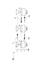
- FIG. 9A is a diagram showing a configuration of a wireless communication system 900.
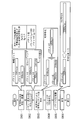
- FIG. 9B is a flowchart illustrating processing of the radio relay station device 93 included in the radio communication system 900.
- “A” is a signal transmitted from the wireless terminal station device 91 (Node 1) at time T1
- “B” is a signal transmitted from the wireless terminal station device 92 (Node 3) at time T2
- “A + B” "Is a signal transmitted from the radio relay station device 93 (Node 2) at time T3. More specifically, FIG.
- FIG. 9A is a diagram showing an outline of communication in the wireless communication system 900 of Alice & Bob topology.
- the wireless terminal station devices 91 and 92 (Node 1 and 3) at both ends perform bidirectional communication with each other via the wireless relay station device 93 (Node 2).
- FIG. 9B is a flowchart showing the relay process of the radio relay station device 93.
- the size of the packet A transmitted from the wireless terminal station device 91 is 1000 bytes
- the size of the packet B transmitted from the wireless terminal station device 92 is 700 bytes.
- a packet is information to be transmitted, and a modulation symbol is a signal obtained by modulating (mapping) a bit signal included in a packet or the like in a baseband, and an RF (Radio Frequency) signal. Is a signal obtained by up-converting modulation symbols to the RF band.
- the wireless terminal station device 91 transmits the RF signal A of the packet A to the wireless relay station device 93 and stores the packet A.
- the wireless relay station device 93 receives the RF signal A transmitted from the wireless terminal station device 91, and stores the packet A obtained by decoding the received RF signal A.
- the wireless terminal station device 92 transmits the RF signal B of the packet B to the wireless relay station device 93 and stores the packet B.
- the wireless relay station device 93 receives the RF signal B transmitted from the wireless terminal station device 92, and stores the packet B obtained by decoding the received RF signal B (step S901).
- the radio relay station device 93 compares the packet lengths L A (1000 bytes) and L B (700 bytes), and the data length is at the end of the information bit sequence of the packet B having a shorter packet length.
- (300 bytes) is added to align the packet lengths of packet A and packet B (step S902).
- the wireless relay station device 93 generates one NC packet C by NC encoding the packet A and the packet B by exclusive OR (step S903), and the encoding rate for the generated NC packet C is high. 1/2 error correction coding is performed (step S904).
- the radio relay station device 93 broadcasts the RF signal C obtained by modulating and up-converting the NC packet C subjected to error coding to the radio terminal station devices 91 and 92 (steps S905 and S906). ).
- This broadcast transmission is to simultaneously transmit the same information to a plurality of destination stations by using the broadcast property of wireless communication by designating a plurality of wireless terminal station devices as the destination station of the header information.
- the packet length of each of packet A and packet B is included in the header information together with information indicating the destination station.
- the wireless terminal station devices 91 and 92 acquire the packet length from the header information of the received RF signal C.
- the wireless terminal station device 91 Upon receiving the RF signal C transmitted from the wireless relay station device 93, the wireless terminal station device 91 adjusts the output level by AGC (Auto Gain Control) using the received RF signal C, and The received RF signal C is down-converted and demodulated to obtain an NC packet C.
- AGC Automatic Gain Control
- the wireless terminal station device 91 is zero-padded by performing zero padding of the difference between the two packet lengths on the packet A
- the packet length of the packet A is made the same as the packet length of the NC packet C, and NC decoding is performed by exclusive OR operation between the zero-padded packet A and the NC packet C to obtain a packet B.
- the wireless terminal station device 91 performs an exclusive OR operation between the NC packet C and the packet A to perform the NC operation. Decrypt. And the radio
- the wireless terminal station device 92 also demodulates the NC packet C from the RF signal C.
- the wireless terminal station device 92 is zero-padded by performing zero-padding of the difference between the two packet lengths on the packet B.
- Packet A is acquired by aligning the packet length of packet B with the packet length of NC packet C and performing NC decoding by exclusive OR operation.
- the wireless terminal station device 92 performs NC decoding by exclusive OR operation between the NC packet C and the packet B. .
- the wireless terminal station device 92 acquires the packet A by deleting the portion added by zero padding from the packet obtained by NC decoding.
- the wireless relay station device 93 performs broadcast transmission of the packets received from the wireless terminal station devices 91 and 92 at the same time, thereby reducing the number of time slots by one time slot as compared with the case where the packets are individually relayed.
- the packet B can be transmitted to the wireless terminal station device 91 and the packet A can be transmitted to the wireless terminal station device 92 by the time slot.
- NC encoding is performed in units of bits
- bit length (information amount) of NC packets to be NC-encoded needs to be the same. Therefore, in network coding, processing is performed to make the packet lengths of the respective native packets the same by performing zero padding on the information bit sequences of the respective native packets. Specifically, with respect to other native packets having a relatively short packet length so as to be the same length as the packet having the longest packet length (hereinafter referred to as max_L) among the NC-encoded native packets.
- the bits are made the same by adding bits by zero padding.
- NC coding is performed on an information bit sequence which is a native packet having the same packet length, and error correction (FEC) coding is performed on the information bit sequence of the NC packet. Therefore, zero padding for aligning the packet length is performed on the information bit sequence before NC encoding.
- FEC error correction
- the coding rate for satisfying the required transmission quality may differ depending on the propagation path environment at the second hop of each packet.
- the second hop refers to transmitting (relaying) a packet received from a wireless terminal station device having a wireless relay station device to another wireless terminal station device.
- the NC packet C is subjected to error correction coding at the lowest coding rate among the required coding rates.
- the data length Lc of the NC packet C is the longest data length max_L among the packet lengths of the received packets, and the lowest coding rate (hereinafter referred to as min_R) among the required coding rates.
- the present invention has been made to solve the above problems, and its object is to provide a wireless communication system, a wireless relay station device, and a wireless terminal station using network coding that can set transmission quality for each destination of a packet and improve throughput.
- An apparatus and a wireless communication method are provided.
- the present invention provides a radio relay station apparatus that transmits different first and second packets to a plurality of radio terminal station apparatuses, wherein the first packet and the second packet A coding rate used for each of the first packet and the second packet is selected according to communication quality required for each packet, and each of the first packet and the second packet is selected using the selected coding rate.
- An error correction encoding unit for generating an error correction encoded packet having the same data length from the network, and performing network encoding on the error correction encoded first packet and the second packet to generate a network encoded packet A network encoding circuit for generating a network encoding packet, and a transmission circuit for transmitting the network encoded packet to the plurality of wireless terminal stations. That is a radio relay station device.
- the error correction encoding unit performs packet correction when error correction encoding is performed at an encoding rate required for each of the first packet and the second packet.
- the coding rate corresponding to a packet with a short calculated packet length is reduced, and the first packet that has been subjected to error correction coding and the second packet that has been subjected to error correction coding have the same packet length.
- Such error correction coding may be performed.
- the error correction encoding unit performs error correction encoding on each of the first packet and the second packet
- the data length is short.
- a concatenated bit obtained by copying a bit included in the error correction encoded packet is generated, and the concatenated bit is added to the error correction encoded packet having a short data length to add the first packet and the second packet.
- the lengths of error-corrected encoded data may be the same.
- the error correction encoding unit when orthogonal multilevel modulation is used for radio transmission from the radio relay station apparatus to the plurality of radio terminal station apparatuses, the error correction encoding unit The least significant bit among the bits constituting the modulation symbol generated by modulation may be preferentially selected as the copy source bit of the concatenated bit.
- the error correction encoding unit may arrange the concatenated bits collectively at a predetermined position in an error correction encoded packet having a short data length. May be.
- the error correction encoding unit configures the concatenated bit copied from the copy source bit at a position adjacent to the copy source bit of each bit configuring the concatenated bit. Each bit may be arranged.
- the error correction encoding unit may configure each bit constituting the concatenated bit at a position spaced apart from a copy source bit of each bit constituting the concatenated bit by a certain bit interval. May be arranged.
- the present invention is a wireless communication system including a wireless relay station device that transmits different first packets and second packets to a plurality of wireless terminal station devices, wherein the wireless relay station device A coding rate to be used for each of the first packet and the second packet is selected according to communication quality required for each of the first packet and the second packet, and the first coding is performed using the selected coding rate.
- An error correction encoding unit for generating an error correction encoded packet having the same data length from each of the packet and the second packet, and network encoding for the error correction encoded first packet and the second packet
- a network encoding circuit for generating a network encoded packet by performing the network encoded packet and the plurality of wireless terminal stations
- a wireless terminal station device that stores a third packet identical to the first packet in a storage circuit, and the plurality of wireless terminal stations.
- each wireless terminal station device storing a third packet identical to the second packet in a storage circuit includes an error correction coding circuit for performing error correction coding on the third packet, and a reception A network decoding circuit for network-decoding the network-encoded packet using the third packet that has been error-correction-encoded to generate a decoded packet; and an error-correction decoding unit that performs error-correction decoding on the decoded packet;
- a wireless communication system A wireless communication system.
- the error correction coding unit may calculate a packet length when error correction coding is performed at a coding rate required for each of the first packet and the second packet.
- the coding rate corresponding to a packet with a short calculated packet length is calculated, and the first packet subjected to error correction coding and the second packet subjected to error correction coding have the same packet length. Error correction coding may be performed.
- an error with a short data length is generated.
- An error of the first packet and the second packet is generated by generating a concatenated bit by copying a bit included in the correction-encoded packet and adding the concatenated bit to the error-correction-encoded packet having a short data length.
- the correction-encoded data length is the same, and the error correction decoding unit cuts out the error-correction encoded packet and the concatenated bit having a shorter data length than the decoded packet, and performs error correction encoding with the short data length.
- the error correction decoding may be performed by combining the packet and the concatenated bit with a soft decision value.
- the error correction encoding unit when orthogonal multilevel modulation is used for radio transmission from the radio relay station apparatus to the plurality of radio terminal station apparatuses, the error correction encoding unit includes the orthogonal multilevel modulation.
- the least significant bit of the bits constituting the modulation symbol generated by the above may be preferentially selected as the copy source bit of the concatenated bit.
- the error correction encoding unit may arrange the concatenated bits collectively at a predetermined position in an error correction encoded packet having a short data length. Also good.
- the error correction encoding unit may configure each of the concatenated bits copied from the copy source bits at positions adjacent to the copy source bits of the bits composing the concatenated bits. Bits may be arranged.
- the error correction encoding unit may set each bit constituting the concatenated bit at a position spaced apart from a copy source bit of each bit constituting the concatenated bit by a certain bit interval. It may be arranged.
- the present invention is a wireless terminal station apparatus in a wireless communication system including a wireless relay station apparatus that transmits different first packets and second packets to a plurality of wireless terminal station apparatuses, wherein the wireless relay station The station apparatus selects a coding rate used for each of the first packet and the second packet according to communication quality required for each of the first packet and the second packet, and selects the selected coding rate. Using the first packet and the second packet to generate an error correction encoded packet having the same data length, and performing network encoding on the error correction encoded first packet and the second packet.
- a receiving circuit that receives the generated network-encoded packet and the same as either the first packet or the second packet
- a storage circuit that stores a third packet; an error correction encoding circuit that performs error correction encoding on the third packet; and the received network encoded packet that has been error-corrected encoded
- a wireless terminal station apparatus includes a network decoding circuit that performs network decoding using a packet and generates a decoded packet, and an error correction decoding unit that performs error correction decoding on the decoded packet.
- the present invention is a radio communication method in a radio communication system including a radio relay station apparatus that transmits different first packets and second packets to a plurality of radio terminal station apparatuses, wherein the radio relay station
- the error correction coding unit of the device selects and selects a coding rate to be used for each of the first packet and the second packet according to communication quality required for each of the first packet and the second packet.
- a process of generating an error correction encoded packet having the same data length from each of the first packet and the second packet using the encoded rate, and a network encoding circuit of the radio relay station apparatus includes an error correction code Performing network coding on the converted first packet and second packet to generate a network coded packet
- a transmission circuit of the radio relay station apparatus transmitting the network-encoded packet to the plurality of radio terminal station apparatuses; and a third packet identical to the first packet among the plurality of radio terminal station apparatuses
- the error correction encoding circuit of the wireless terminal station apparatus storing the data in the storage circuit performs error correction encoding on the stored third packet, and among the plurality of wireless terminal station apparatuses,
- a network decoding circuit of the plurality of wireless terminal station devices performs network decoding on the received network encoded packet with the third packet
- transmission quality can be set for each destination of a packet, and throughput of the wireless communication system can be improved.
- FIG. 10 is a flowchart showing processing of the radio relay station device 93 included in the radio communication system 900.
- FIG. 1 is a schematic diagram illustrating a configuration of a wireless communication system 100 according to the first embodiment.
- the radio communication system 100 includes radio terminal station devices 10a and 10b arranged at both ends, and a radio relay station device 20 arranged between the radio terminal station devices 10a and 10b.
- the wireless terminal station devices 10a and 10b have the same configuration, and when one or both of them are indicated, the wireless terminal station devices 10a and 10b are referred to as wireless terminal station devices 10.
- A is a signal transmitted from the wireless terminal station device 10a (wireless terminal station device 30a in the second embodiment to be described later) (Node 1) at time T1
- B is a wireless terminal at time T2.
- a + B” is the wireless relay station device 20 (wireless relay station device 40 in the second embodiment) (Node2) at time T3. ).
- FIG. 2 is a schematic block diagram showing the configuration of the wireless terminal station device 10 in the same embodiment.
- the wireless terminal station device 10 includes an error correction coding circuit 11, a transmission packet storage circuit 12, a modulation circuit 13, a wireless unit 14, a demodulation circuit 15, a bit soft decision circuit 16, a replica.
- a packet generation unit 17, an NC (network coding) decoding circuit 18, and an error correction decoding unit 19 are provided.
- the error correction decoding unit 19 has an error correction decoding circuit 191.
- a packet to be transmitted is input to the error correction encoding circuit 11 and the transmission packet storage circuit 12.
- the error correction encoding circuit 11 performs error correction encoding on the input packet, and outputs the error correction encoded packet to the modulation circuit 13.
- the transmission packet storage circuit 12 stores the input packet.
- the modulation circuit 13 modulates (maps) each bit information included in the error-correction encoded packet with baseband to generate a modulation symbol, and outputs the generated modulation symbol to the radio unit 14.
- the radio unit 14 up-converts the modulation symbol output from the modulation circuit 13 and converts it into an RF signal, and transmits the converted RF signal via an antenna. Further, the radio unit 14 adjusts the output level by AGC (Auto Gain Control) using the RF signal received via the antenna, and down-converts the received RF signal to convert it into a modulation symbol.
- the converted modulation symbol is output to the demodulation circuit 15.
- the demodulation circuit 15 outputs a signal obtained by demodulating (demapping) the modulation symbol output from the radio unit 14 in the baseband to the bit soft decision circuit 16, and also receives the header information received together with the packet as the replica packet generation unit 17 and the error. It outputs to the correction decoding part 19.
- the bit soft decision circuit 16 performs a soft decision on the signal input from the demodulation circuit 15 and outputs a soft decision signal including a soft decision value for each information bit of the packet to the NC decoding circuit 18.
- the replica packet generation unit 17 reads the packet stored in the transmission packet storage circuit 12, performs error correction coding of the read packet based on the coding rate included in the header information input from the demodulation circuit 15, and generates an error.
- a replica packet which is a correction-encoded packet, is generated and output to the NC decoding circuit 18.
- the NC decoding circuit 18 outputs a packet obtained by NC decoding the soft decision signal of the packet input from the bit soft decision circuit 16 using the replica packet input from the replica packet generation unit 17 to the error correction decoding circuit 191. .
- the error correction decoding circuit 191 decodes the packet by performing error correction decoding on the packet decoded by the NC decoding circuit 18 and outputs the decoded packet.
- FIG. 3 is a schematic block diagram showing the configuration of the radio relay station device 20 in the same embodiment.
- the radio relay station device 20 includes a radio unit 21, a demodulation circuit 22, a bit soft decision circuit 23, an error correction decoding circuit 24, a packet storage circuit 25, an error correction encoding unit 26, An NC encoding circuit 27 and a modulation circuit 28 are provided.
- the error correction coding unit 26 includes a coding rate setting circuit 261 and error correction coding circuits 262 and 263.
- the radio unit 21 adjusts an output level by AGC (Auto Gain Control) using an RF signal received via an antenna, down-converts the received RF signal to convert it into a modulation symbol, The converted modulation symbol is output to the demodulation circuit 22.
- AGC Automatic Gain Control
- the demodulation circuit 22 outputs a signal obtained by demodulating (demapping) the modulation symbol output from the radio unit 21 in the baseband to the bit soft decision circuit 23. Further, the demodulation circuit 22 outputs the packet header information to the error correction decoding circuit 24 and the error correction encoding unit 26.
- the bit soft decision circuit 23 performs a soft decision on the signal input from the demodulation circuit 22 and outputs a soft decision signal including a soft decision value for each information bit of the packet to the error correction decoding circuit 24.
- the error correction decoding circuit 24 performs error correction on the soft decision signal of the packet input from the bit soft decision circuit 23 based on the coding rate of the packet to be decoded included in the header information input from the demodulation circuit 22.
- the packet is decoded by performing decoding, and the decoded packet is output to the packet storage circuit 25.
- the packet storage circuit 25 stores the packet input from the error correction decoding circuit 24.
- the data length D A> D B after error correction coding coding rate setting circuit 261
- a code rate for the packet B R B from R B ' L B / ( L A / R A)
- the coding rate R A is output to the error correction coding circuit 262, and the coding rate R B ′ is output to the error correction coding circuit 263.
- the coding rates R A and R B used in the coding rate setting circuit 261 are determined based on the transmission path characteristics estimated when communicating with the wireless terminal station device 10 and the required communication quality. Alternatively, the value is determined in advance by, for example, notifying the coding rate for each packet from the wireless terminal station device 10 in advance.
- the error correction coding circuits 262 and 263 read the packet from the packet storage circuit 25, perform error correction coding on the packet read at the coding rate input from the coding rate setting circuit 261, and perform error correction coding.
- the packet is output to the NC encoding circuit 27.
- the error correction encoding circuits 262 and 263 include an encoder for realizing the encoding rate input from the encoding rate setting circuit 261 and a code book in which a bit puncture pattern is finely defined. Processing is performed according to the codebook index stored in advance and input from the coding rate setting circuit 261.
- the codebook index is included in the header information together with the NC-encoded packet and transmitted to the wireless terminal station device 10.
- the NC encoding circuit 27 performs NC encoding with a linear code on the error correction encoded packets input from the error correction encoding circuits 262 and 263, and sends the NC encoded packets to the modulation circuit 28. Output.
- a function having linearity such as an XOR (exclusive OR) operation is used.
- the modulation circuit 28 outputs a modulation symbol obtained by modulating and converting the packet encoded by the NC encoding circuit 27 in the baseband to the radio unit 21.
- FIG. 4 is a flowchart showing the operation of the radio relay station device 20 in the embodiment.
- a packet length L A and L B, the coding rate R A and R B and is the case in the following will be described.
- the coding rate R A required to satisfy the above condition is 2/3.
- the packet A to be transmitted is input to the error correction encoding circuit 11 and the transmission packet storage circuit 12.
- the error correction encoding circuit 11 performs error correction encoding on the input packet A, and outputs the error correction encoded packet A to the modulation circuit 13.
- the transmission packet storage circuit 12 stores the input packet A.
- the modulation circuit 13 modulates the error correction encoded packet A and converts it into a modulation symbol A, and outputs the converted modulation symbol A to the radio unit 14.
- the radio unit 14 up-converts the input modulation symbol A to generate an RF signal A, and transmits the generated RF signal A to the radio relay station device 20 via an antenna.
- radio section 21 receives RF signal A via an antenna, down-converts received RF signal A and converts it into modulation symbol A, and the converted modulation symbol A is output to the demodulation circuit 22.
- the demodulation circuit 22 outputs a signal of the packet A obtained by demodulating (demapping) the input modulation symbol A to the bit soft decision circuit 23.
- the bit soft decision circuit 23 performs soft decision on the input packet A signal and outputs the soft decision signal of packet A to the error correction decoding circuit 24.
- the error correction decoding circuit 24 causes the packet storage circuit 25 to store the packet A obtained by performing error correction decoding on the soft decision signal of the input packet A.
- the packet B to be transmitted is input to the error correction coding circuit 11 and the transmission packet storage circuit 12, and the wireless terminal station device 10b is connected to the wireless terminal station device 10a.
- the packet B is converted into the RF signal B by the same procedure as described above and transmitted to the radio relay station apparatus 20.
- the radio unit 21 receives the RF signal B via the antenna, and stores the packet B obtained by demodulation and error correction decoding in the packet storage circuit 25, as with the RF signal A.
- the radio relay station apparatus 20 receives and demodulates the packet A and the packet B, and stores them in the packet storage circuit 25 (step S101).
- the coding rate setting circuit 261 reads the packets A and B from the packet storage circuit 25, and reads the read packet A with the coding rate R A required for the packet A.
- the NC encoding circuit 27 performs NC encoding on the error correction encoded packets A and B input from the error correction encoding circuits 262 and 263 to generate an NC packet C (step S104).
- the modulation circuit 28 modulates the NC packet C generated by the NC encoding circuit 27 and converts it into a modulation packet C.
- the radio unit 21 up-converts the modulation packet C converted by the modulation circuit 28 to convert it into an RF signal C, and transmits the converted RF signal C to the radio terminal station apparatuses 10a and 10b via the antenna (step). S105, S106).
- the wireless unit 14 down-converts the received RF signal C and converts it into a modulated packet C.
- the bit soft decision circuit 16 performs a soft decision on the signal of the NC packet C demodulated by the demodulation circuit 15, generates a soft decision signal of the NC packet C, and outputs it to the NC decoding circuit 18.
- the replica packet generation unit 17 reads the packet A from the transmission packet storage circuit 12, performs error correction coding on the read packet A with the coding rate R A input from the demodulation circuit 15, and performs error correction coding.
- the packet A is output to the NC decoding circuit 18.
- the NC decoding circuit 18 performs an XOR operation on the NC packet C input from the bit soft decision circuit 16 and the error correction encoded packet A input from the replica packet generation unit 17 to perform NC decoding, thereby obtaining an error.
- a correction-encoded packet B is calculated.
- the wireless terminal station device 10b Similarly to the wireless terminal station device 10a, the wireless terminal station device 10b generates a replica packet from the packet B stored in the transmission packet storage circuit 12, and performs NC decoding by using the generated replica packet to perform wireless decoding.
- the packet A is calculated and acquired from the RF signal C received by the unit 14.
- the wireless communication system 100 transmits the packet A and the packet B.
- the error correction encoding unit 26 performs error correction encoding on the packets A and B, respectively. I made it. Thereby, different coding rates can be applied to the packet A and the packet B, and the increase in the data length of the packet to be transmitted as shown in FIG. 9B can be suppressed, and the inefficiency can be eliminated.
- the coding rate setting circuit 261 calculates the data length when the error correction coding is performed at the coding rate required for each of the packet A and the packet B, and reduces the coding rate of the packet with a short data length.
- the data lengths after error correction coding of both are made the same, so that the coding rate applied to each of packet A and packet B can satisfy the coding rate required for the required communication quality.
- the zero padding adds redundant data that does not contribute to error correction, the data length after error correction coding is made uniform by changing the coding rate for packet A and packet B. , Transmission quality can be improved.
- the radio communication system 200 includes two radio terminal station devices 30a and 30b and a radio relay station device 40, similarly to the radio communication system 100 according to the first embodiment illustrated in FIG. .
- the radio terminal station devices 30a and 30b have the same configuration, and when one or both of them are referred to, the radio terminal station devices 30a and 30b are referred to as radio terminal station devices 30.
- FIG. 5 is a schematic block diagram showing the configuration of the radio relay station device 40 in the second embodiment.
- the radio relay station device 40 includes a radio unit 21, a demodulation circuit 22, a bit soft decision circuit 23, an error correction decoding circuit 24, a packet storage circuit 25, an error correction encoding unit 46, An NC encoding circuit 27 and a modulation circuit 28 are provided.
- the error correction encoding unit 46 includes a data length comparison circuit 461, error correction encoding circuits 462 and 463, and bit connection circuits 464 and 465.
- the same components as those of the radio relay station device 20 of the first embodiment are denoted by the same reference numerals (21 to 25, 27 to 28), and the description thereof is omitted.
- This packet length adjustment information is information including an instruction to add a concatenated bit having a data length of
- the concatenated bit is a bit obtained by copying a bit included in an error correction encoded packet to be added. Further, the data length comparison circuit 461 outputs to the modulation circuit 28 the packet to which the concatenated bit is added and the concatenated bit information indicating the data length of the added concatenated bit.
- the concatenated bit information is included in the header information of the packet together with the coding rates of the packet A and the packet B, and is transmitted to the wireless terminal station device 30.
- the error correction encoding circuits 462 and 463 read packets from the packet storage circuit 25 and perform encoding according to the communication quality required for each packet. Error correction encoding is performed at a rate, and the error correction encoded packet is output to bit concatenation circuits 464 and 465.
- the coding rate corresponding to the required communication quality is calculated based on the propagation path condition between the local station and the packet destination wireless terminal station device 30, or the packet destination wireless terminal station device. This value is determined in advance before the error correction encoding circuits 462 and 463 perform error correction encoding, for example, by specifying 30.
- the bit concatenation circuit 464 When the packet length adjustment information is input from the data length comparison circuit 461, the bit concatenation circuit 464 generates a concatenated bit having a data length of
- Bit concatenation circuit 465 has the same configuration as bit concatenation circuit 464, and is input from error correction encoding circuit 463 depending on whether or not packet length adjustment information is input from data length comparison circuit 461. The concatenated bit is added to the error correction encoded packet and output to the NC encoding circuit 27.
- the copy source of the concatenated bits is selected as follows.
- D 1 ⁇ D C the copy source bit is selected according to the bit number bn expressed by the following equation (1).
- the copy source bits are selected and copied so that the distances between the copy source bits are the largest and at equal intervals.
- a can be arbitrarily set within the above range.
- FIG. 6A to 6C are diagrams showing examples of concatenated bit arrangement positions (bit sequences after adjustment of packet length) in the embodiment.
- FIG. 6A shows an example in which copy bit sequences are collectively arranged at an arbitrary position in the original bit sequence.
- FIG. 6B shows an example in which copy bits are arranged so that the positions of the copy source bit and the copy bit are as close as possible.
- FIG. 6C shows an example in which copy bits are arranged so that the positions of the copy source bit and the copy bit are as far as possible.
- D 1 3200 bits
- D 2 4000 bits
- D C 800 bits
- a 1, the first bit, the fifth bit, the ninth bit,.
- the 3197th bit is selected as the copy source.
- D 1 ⁇ D C when D C is an integer multiple of D 1 , the entire error correction coded packet is selected as a copy source bit, and the selected bit is (D C / D 1 ). Copy once. Further, when D C is not an integer multiple of D 1, select the entire packet error-correction-coded as a copy source bits, the selected bit to floor (D C / D 1) partial copy, missing parts for D 1 ⁇ D C and select the copy source bits similarly for (fractional part), copies the selected bits.
- floor (X) is a floor function, and represents a maximum integer equal to or smaller than X with respect to the real number X.
- the position where the copy source bit is selected and the copied bit is arranged is the end of the error-corrected encoded packet, and all concatenated bits (concatenated copy bits) are placed at the end of the packet. Append to the tail.
- a copy bit is added to the tail of an error correction encoded packet, but the position where the copy bit is added may be any position of the error correction encoded packet, for example, A copy bit may be added to the head.
- the bit concatenation circuits 464 and 465 select a copy source bit from a packet having a short data length after error correction coding, and copy bit (concatenated bit) obtained by copying the information of the copy source bit in the packet. Are arranged at predetermined positions. As a result, the data lengths of the two error-correction-encoded packets are made uniform, and the coding rate is substantially reduced for packets having a short data length after error-correction encoding.
- the above-described copy source bit selection method and the position where the copy bit is added are determined in advance, and are shared in advance between the radio relay station device 40 and the radio terminal station device 30.
- the copy bit arrangement position may be a position adjacent to the copy source bit as shown in FIG. 6B.
- the copy bit arrangement position may be a position where a certain bit interval is provided between the copy source bit and the copy bit. That is, the copy bits may be arranged at equal intervals one bit at a time.
- the constant bit interval is calculated from the relationship between the data length D 1 of the error correction encoded packet having a short data length and the data length D C of the concatenated bits, for example, floor (D 1 / D C ). .
- the correlation between the copy source bit and the copy bit can be lowered, and the diversity effect by the soft decision value synthesis can be improved in the wireless terminal station device 30.
- FIG. 6A in FIG.
- D 1 3200 bits
- D 2 4000 bits
- D C 800 bits
- a 1.
- D 1 > D 2 it can be dealt with by replacing D 1 and D 2 in the above description.
- a bit sequence obtained by performing interleaving on copy bits may be arranged using an interleaver dedicated to copy bit sequences.
- FIG. 7 is a schematic block diagram showing the configuration of the wireless terminal station device 30 in the same embodiment.
- the wireless terminal station device 30 includes an error correction coding circuit 11, a transmission packet storage circuit 12, a modulation circuit 13, a wireless unit 14, a demodulation circuit 15, a bit soft decision circuit 16, a replica, A packet generation unit 37, an NC decoding circuit 18, and an error correction decoding unit 39 are provided.
- the error correction decoding unit 39 includes a packet extraction circuit 391, a concatenated bit extraction circuit 392, a soft decision value synthesis circuit 393, and an error correction decoding circuit 394.
- the same components as those of the wireless terminal station device 10 (FIG. 2) of the first embodiment are denoted by the same reference numerals (11 to 16, 18), and description thereof is omitted.
- the replica packet generation unit 37 reads the packet stored in the transmission packet storage circuit 12 and performs error correction coding on the read packet based on the coding rate included in the header information input from the demodulation circuit 15 I do. Further, the replica packet generation unit 37 generates a concatenated bit based on the concatenated bit information included in the header information, generates a replica packet in which the generated concatenated bit is added to a packet obtained by error correction coding, and is generated. The replica packet is output to the NC decoding circuit 18.
- the packet cutout circuit 391 deletes the concatenated bit from the NC-decoded packet by the NC decoding circuit 18, and performs soft decision on the packet from which the concatenated bit has been deleted.
- the value is output to the value synthesis circuit 393.
- the concatenated bit cut-out circuit 392 extracts concatenated bits from the packet NC-decoded by the NC decoding circuit 18 based on the concatenated bit information included in the header information input from the demodulating circuit 15, and the extracted concatenated bits are soft-decision values. The result is output to the synthesis circuit 393.
- the soft decision value synthesis circuit 393 performs soft decision value synthesis (Soft Combining) on the packet input from the packet cutout circuit 391 and the concatenated bit input from the concatenated bit cutout circuit 392, and error correction is performed on the soft decision value combination result.
- the data is output to the decoding circuit 394.
- the soft decision value synthesis is to add a concatenated bit represented by using a soft decision value and a bit that is a copy source of the concatenated bit.
- the error correction decoding circuit 394 performs error correction decoding on the packet input from the soft decision value synthesis circuit 393 based on the coding rate included in the header information input from the demodulation circuit 15, and the decoded packet Is output.
- FIG. 8 is a flowchart showing the operation of the radio relay station device 40 in the same embodiment.
- a packet length L A and L B, the coding rate R A and R B and is the case in the following will be described.
- the coding rate R A required to satisfy the quality is set to 2/3.
- the packet A to be transmitted is input to the error correction encoding circuit 11 and the transmission packet storage circuit 12.
- the error correction encoding circuit 11 performs error correction encoding on the input packet A, and outputs the error correction encoded packet A to the modulation circuit 13.
- the transmission packet storage circuit 12 stores the input packet A.
- the modulation circuit 13 modulates the error correction encoded packet A and converts it into a modulation symbol A.
- the radio unit 14 up-converts the modulation symbol A converted by the modulation circuit 13 to generate an RF signal A, and transmits the generated RF signal A to the radio relay station device 40 via an antenna.
- the radio unit 21 receives the RF signal A via the antenna, down-converts the received RF signal A and converts it into a modulation symbol A.
- the demodulation circuit 22 outputs a signal obtained by demodulating the modulation symbol A converted by the radio unit 21 to the bit soft decision circuit 23.
- the bit soft decision circuit 23 performs a soft decision on the input packet A signal to generate a packet A soft decision signal.
- the error correction decoding circuit 24 causes the packet storage circuit 25 to store the packet A obtained by performing error correction decoding on the soft decision signal of the packet A generated by the bit soft decision circuit 23.
- the wireless terminal station device 30b receives the packet B to be transmitted to the error correction coding circuit 11 and the transmission packet storage circuit 12, and the wireless terminal station device 30b is connected to the wireless terminal station device 30a.
- the packet B is converted into the RF signal B by the same procedure, and the converted RF signal B is transmitted to the radio relay station device 40.
- the radio unit 21 receives the RF signal B via the antenna, and stores the packet B obtained by demodulation and error correction decoding in the packet storage circuit 25 in the same manner as the RF signal A ( Step S201).
- the data length comparison circuit 461 calculates the difference between the calculated data length D A and the data length D B and outputs packet length adjustment information to the bit connection circuit 465.
- the packet length adjustment information includes information indicating the difference (100 bytes) between the data lengths of the packet A and the packet B after error correction encoding, and a packet B obtained by error correction encoding the concatenated bits of the data length of the difference. And an instruction to be added.
- the error correction coding circuit 462 performs error correction coding on the packet A read from the packet storage circuit 25 at a coding rate R A required for the packet A, and the error correction coded packet A is bit-coupled circuit 464. Output to. Error correction encoding circuit 463, the packet B read from the packet storage circuit 25, and error correction encoding by the encoding rate R B required for packet B, an error correction encoded packet B the bit coupling circuit 465 Output to.
- the bit concatenation circuit 464 outputs the error correction encoded packet A input from the error correction encoding circuit 462 to the NC encoding circuit 27.
- the NC encoding circuit 27 performs NC encoding on the error correction encoded packet A and packet B ′ to generate an NC packet C (step S204).
- the modulation circuit 28 modulates the NC packet C generated by the NC encoding circuit 27 and converts it into the modulation packet C (step S205).
- the radio unit 21 up-converts the modulation packet C converted by the modulation circuit 28 to convert it into an RF signal C, and transmits the converted RF signal C to the radio terminal station devices 30a and 30b via the antenna (step). S206).
- the wireless unit 14 down-converts the received RF signal C and converts it into a modulated packet C.
- the demodulating circuit 15 demodulates the modulated packet C converted by the radio unit 14 to generate a signal of the NC packet C and output the signal to the bit soft decision circuit 16, as well as header information of the modulated packet C and the data length of the NC packet C Is output to the replica packet generation unit 37, and the header information is also output to the error correction decoding unit 39.
- the bit soft decision circuit 16 performs a soft decision on the input NC packet C signal and outputs the NC packet C soft decision signal to the NC decoding circuit 18.
- the NC decoding circuit 18 performs NC decoding on the soft decision signal of the NC packet C input from the bit soft decision circuit 16 using the error correction encoded packet A input from the replica packet generation unit 37. Then, the error correction encoded packet B ′ is calculated, and the error correction encoded packet B ′ is output to the packet cutout circuit 391 and the concatenated bit cutout circuit 392.
- the packet cut-out circuit 391 deletes the concatenated bits included in the error correction encoded packet B ′ and outputs the error correction encoded packet B to the soft decision value synthesis circuit 393.
- the concatenated bit cutout circuit 392 cuts out the concatenated bits included in the error-correction-encoded packet B ′ and outputs the cut out concatenated bits to the soft decision value synthesis circuit 393.
- the error correction decoding circuit 394 performs error correction decoding on the error correction encoded packet B input from the soft decision value synthesis circuit 393 to calculate the packet B, and outputs the calculated packet B to an upper layer or the like.
- the wireless unit 14 down-converts the received RF signal C and converts it into a modulation symbol C.
- the NC decoding circuit 18 performs NC decoding on the input NC packet C using the input error correction encoded packet B ′ to calculate an error correction encoded packet A, and calculates the calculated error correction encoded packet A is output to the packet cutout circuit 391 and the concatenated bit cutout circuit 392.
- the packet cutout circuit 391 outputs the input error correction encoded packet A to the soft decision value combining circuit 393 according to the concatenated bit length (zero) input from the demodulation circuit 15.
- the concatenated bit cut-out circuit 392 generates information indicating that there is no concatenated bit added according to the concatenated bit length (zero) of the packet A included in the header information input from the demodulation circuit 15, and the soft decision value synthesis circuit 393. Output to.
- the soft decision value combining circuit 393 does not combine anything with the input error correction encoded packet A and outputs it to the error correction decoding circuit 394. That is, the soft decision value combining circuit 393 outputs the input error correction.
- the encoded packet A is output to the error correction decoding circuit 394.
- the error correction decoding circuit 394 calculates the packet A by performing error correction decoding on the error correction encoded packet A input from the soft decision value synthesis circuit 393, and outputs the calculated packet A to an upper layer or the like.
- the wireless communication system 200 transmits the packet A and the packet B.
- the error correction encoding unit 46 performs error correction encoding on the packets A and B, respectively. I made it.
- different coding rates can be applied to the packet A and the packet B, and the increase in the data length of the packet to be transmitted as shown in FIG. 9B can be suppressed, and the inefficiency can be eliminated.
- the bit concatenation circuits 464 and 465 generate error correction codes when there is a difference in data length when error correction coding is performed on the packets A and B at the required coding rates.
- the concatenated bits obtained by copying the bits included in the converted packet are added to the error correction encoded packet so that the data length is the same. Then, in the wireless terminal station devices 30a and 30b, the error correction decoding unit 39 performs error correction by adding the concatenated bits by performing a soft decision value combining using the added concatenated bits to obtain a diversity effect. The reliability of the encoded packet can be improved.
- the radio communication system 200 adds a concatenated bit after error correction coding when the coding rate that can be selected by the radio terminal station device 30 and the radio relay station device 40 is limited.
- the data lengths of packets to be NC-encoded can be made uniform by simple processing. Therefore, it is effective even when the coding rate cannot be freely selected as in the wireless communication system 100 of the first embodiment.
- the bit connection circuits 464 and 465 may use a selection method other than the copy source bit selection method described above.
- the modulation scheme used in the radio transmission from the radio relay station apparatus 20 (40) to the radio terminal station apparatus 10 (30) is an orthogonal of 16QAM (Quadrature Amplitude Modulation) or more using gray arrangement.
- 16QAM Quadrature Amplitude Modulation
- the least significant bit of each modulation symbol is preferentially selected as a copy source bit.
- 16QAM the error resilience of the 2 least significant bits indicating the modulation symbol is low, so the copy source bits are selected for every 2 bits to generate concatenated bits.
- D C > D 1/2 not only the least significant bit but also the most significant bit may be selected as the copy source bit, or the least significant bit may be copied a plurality of times.
- 64QAM since the error resistance of the 3 least significant bits indicating the modulation symbol is low, a copy source bit is selected every 3 bits to generate a concatenated bit.
- the D C> D 1/3 not only the least significant bits, may be selected as a copy source bits most significant bit and intermediate bit, so as to copy a plurality of times the least significant bit Also good.
- the Alice & Bob topology is used as the network configuration.
- the present invention is not limited to this, and the network configuration such as an X topology or a chain topology may be used.
- the wireless terminal station device 10 (30) decodes the network-encoded NC packet using the received native packet (packet that is not NC-encoded) instead of the transmitted packet.
- the first embodiment and the second embodiment described above may be used in combination.
- the coding rate setting circuit 261 changes the coding rate according to the packet length after error correction coding, but can be selected when the coding rate that can be selected is limited.
- a coding rate close to a desired coding rate is selected from the coding rates, and the difference in data length generated after error correction coding is made uniform by the concatenated bits. Thereby, a circuit required for error correction coding and error correction decoding can be reduced.
- a plurality of packets may be concatenated in each of the packet A and the packet B, so that the final data length after concatenation may be the same. Since packets of various data lengths flow on the network, the data length of the concatenated packets approaches the same data length statistically by connecting a plurality of packets. As a result, more packets can be transmitted at one time, and the data length of the packets to be network-encoded can be brought close to the same, so that the system throughput can be improved.
- the method of concatenating a plurality of the packets described above and the adjustment of the data length according to the first embodiment and the second embodiment may be combined so that the data lengths resulting from error correction coding of the concatenated packets are made uniform. .
- the radio relay station apparatus may control the packet storage circuit so that network coding is performed between packets having the same QoS class. As a result, the data lengths of packets that are network-encoded can be made uniform, and the system throughput is improved.
- QoS Quality of Service
- packet data storage circuit control method based on the QoS described above may be combined with the adjustment of the data length according to the first and second embodiments to make the final data length uniform.
- the present invention is used, for example, in a wireless communication system to which network coding is applied. According to the present invention, transmission quality can be set for each destination of a packet, and the throughput of the wireless communication system can be improved.
- Packet extraction circuit 392 Concatenated bit extraction circuit 393 ... Soft decision value Forming circuit 394 ... error correction decoding circuit 461 ... data length comparator circuit 462, 463 ... error correction encoding circuit 464 and 465 ... bit connecting circuit
Landscapes
- Engineering & Computer Science (AREA)
- Computer Networks & Wireless Communication (AREA)
- Signal Processing (AREA)
- Quality & Reliability (AREA)
- Mobile Radio Communication Systems (AREA)
- Detection And Prevention Of Errors In Transmission (AREA)
- Radio Relay Systems (AREA)
Abstract
Description
本願は、2009年10月7日に日本へ出願された特願2009-233740号に基づき優先権を主張し、その内容をここに援用する。
この問題を解決する手段として、無線中継局装置が各通信フローのパケットを一旦、ビット信号に復調し、復調したビット信号の系列に対してネットワークコーディング(Network Coding;NC)を施して、ネットワークコーディングされたビット信号の系列を宛先局の無線通信装置に一括送信する技術が提案されている(非特許文献1及び2)。ネットワークコーディングとは、予め定めておいた生成式に基づいて線形符号化することで各通信フローのパケットを重ね合わせる符号化のことである。
以下、あるパケットに対して、ネットワークコーディングを施すことをNC符号化といい、NC符号化されたパケットを復号することをNC復号という。
なお、図9Aにおいて、「A」は時刻T1に無線端末局装置91(Node1)から送信される信号、「B」は時刻T2に無線端末局装置92(Node3)から送信される信号、「A+B」は時刻T3に無線中継局装置93(Node2)から送信される信号である。
より具体的には、図9Aは、Alice&Bobトポロジの無線通信システム900における通信の概要を示す図である。このトポロジにおいて、両端の無線端末局装置91、92(Node1及び3)は、互いに無線中継局装置93(Node2)を介して双方向通信を行う。各ノードの送信は、予め定められたタイムスロットにおいて行われ、各ノードが送信した信号が互いに干渉しないことを前提とした場合について説明する。図9Bは、無線中継局装置93の中継処理を示したフローチャートである。無線端末局装置91から送信されるパケットAのサイズは1000byteであり、無線端末局装置92から送信されるパケットBのサイズは700byteである。また、所定の通信品質を満たすために要求されるパケットAの符号化率RAは2/3であり、パケットBの符号化率RBは1/2である場合について説明する。
なお、パケットとは、送信すべき情報のことであり、変調シンボルとは、パケットなどに含まれるビット信号をベースバンドで変調(マッピング)した信号であり、RF(Radio Frequency;無線周波数)信号とは、変調シンボルをRF帯にアップコンバートした信号である。
次に、時刻T2において、無線端末局装置92は、パケットBのRF信号Bを無線中継局装置93に送信すると共に、パケットBを記憶する。無線中継局装置93は、無線端末局装置92が送信したRF信号Bを受信し、受信したRF信号Bを復号して得られたパケットBを記憶する(ステップS901)。
この同報送信とは、ヘッダ情報の宛先局に複数の無線端末局装置を指定することにより、無線通信の同報性を利用して同時に同じ情報を複数の宛先局に送信することである。また、パケットA及びパケットBそれぞれのパケット長は、宛先局を示す情報と共にヘッダ情報に含まれている。無線端末局装置91、92は、受信したRF信号Cのヘッダ情報からパケット長を取得する。
一方、無線端末局装置91は、NCパケットCのパケット長が記憶しているパケットAのパケット長と同じ長さの場合、NCパケットCとパケットAとの排他的論理和演算を行うことによりNC復号をする。そして、無線端末局装置91は、ヘッダ情報に含まれるパケットBのパケット長に基づいて、NC復号により得られたパケットからパケットBを取得する。
具体的には、NC符号化されるネイティブパケットのうち最も長いパケット長(以下max_Lと記す)を有するパケットと同じ長さになるように、他の相対的に短いパケット長を有するネイティブパケットに対してゼロパディングによりビットを付加してパケット長を同じにしている。上述のようにパケット長を同じ長さに揃えたネイティブパケットである情報ビット系列に対してNC符号化を施し、NCパケットの情報ビット系列に対して誤り訂正(FEC)符号化していた。そのため、パケット長を揃えるためのゼロパディングは、NC符号化前の情報ビット系列に対して行われていた。
このとき、無線中継局装置において、要求される符号化率のうち最も低い符号化率によりNCパケットCを誤り訂正符号化することになる。具体的には、NCパケットCのデータ長Lcは、受信したパケットのパケット長のうち最も長いデータ長max_Lと、要求される符号化率のうち最も低い符号化率(以下min_Rと表記する)とを用いて、データ長Lc=max_L/min_Rと表される。NCパケットCの誤り訂正符号化後のデータ長Lcは、最も長いパケット長と、最も低い符号化率とにより決まってしまうので、伝送するデータ長が長くなりシステムスループットを劣化させる問題があった。
(4)また、上記無線中継局装置において、前記無線中継局装置から前記複数の無線端末局装置への無線伝送に直交多値変調を用いる場合、前記誤り訂正符号化部は、前記直交多値変調により生成される変調シンボルを構成するビットのうちの最下位ビットを前記連結ビットのコピー元のビットとして優先して選択するようにしても良い。
(6)また、上記無線中継局装置において、前記誤り訂正符号化部は、前記連結ビットを構成する各ビットのコピー元ビットの隣接した位置に該コピー元ビットからコピーした前記連結ビットを構成する各ビットを配置するようにしても良い。
(7)また、上記無線中継局装置において、前記誤り訂正符号化部は、前記連結ビットを構成する各ビットのコピー元ビットから一定のビット間隔を隔てた位置に前記連結ビットを構成する各ビットを配置するようにしても良い。
(12)また、上記無線通信システムにおいて、前記誤り訂正符号化部は、前記データ長が短い誤り訂正符号化されたパケット中の予め決められた位置にまとめて前記連結ビットを配置するようにしても良い。
(14)また、上記無線通信システムにおいて、前記誤り訂正符号化部は、前記連結ビットを構成する各ビットのコピー元ビットから一定のビット間隔を隔てた位置に前記連結ビットを構成する各ビットを配置するようにしても良い。
図1は、第1実施形態における無線通信システム100の構成を示す概略図である。ここでは、ネットワーク構成の一例として、Alice&Bobトポロジを用いて説明する。図示するように、本実施形態における無線通信システム100は、両端に配置された無線端末局装置10a、10bと、無線端末局装置10a、10bの間に配置された無線中継局装置20とにより構成されている。また、無線端末局装置10a、10bは、同じ構成を有しており、いずれか一方、或いは、両方を示す場合、無線端末局装置10という。
なお、図1において、「A」は時刻T1に無線端末局装置10a(後述する第2実施形態における無線端末局装置30a)(Node1)から送信される信号、「B」は時刻T2に無線端末局装置10b(第2実施形態における無線端末局装置30b)(Node3)から送信される信号、「A+B」は時刻T3に無線中継局装置20(第2実施形態における無線中継局装置40)(Node2)から送信される信号である。
誤り訂正符号化回路11と送信パケット記憶回路12とには、送信すべきパケットが入力される。誤り訂正符号化回路11は、入力されたパケットに対して誤り訂正符号化を行い、誤り訂正符号化されたパケットを変調回路13に出力する。送信パケット記憶回路12は、入力されたパケットを記憶する。
無線部14は、変調回路13が出力する変調シンボルをアップコンバートしてRF信号に変換して、変換されたRF信号をアンテナを介して送信する。また、無線部14は、アンテナを介して受信したRF信号を用いてAGC(Auto Gain Control;自動利得調整)により出力レベルの調整を行うと共に、受信したRF信号をダウンコンバートして変調シンボルに変換し、変換した変調シンボルを復調回路15に出力する。復調回路15は、無線部14が出力した変調シンボルをベースバンドで復調(デマッピング)した信号をビット軟判定回路16に出力すると共に、パケットと共に受信されたヘッダ情報をレプリカパケット生成部17及び誤り訂正復号部19に出力する。
NC復号回路18は、ビット軟判定回路16から入力されるパケットの軟判定信号をレプリカパケット生成部17から入力されるレプリカパケットによりNC復号して得られたパケットを誤り訂正復号回路191に出力する。誤り訂正復号回路191は、NC復号回路18がNC復号したパケットに対して誤り訂正復号を行うことによりパケットを復号し、復号したパケットを出力する。
無線部21は、アンテナを介して受信したRF信号を用いてAGC(Auto Gain Control;自動利得調整)により出力レベルの調整を行うと共に、受信したRF信号をダウンコンバートして変調シンボルに変換し、変換した変調シンボルを復調回路22に出力する。復調回路22は、無線部21が出力した変調シンボルをベースバンドで復調(デマッピング)した信号をビット軟判定回路23に出力する。また、復調回路22は、パケットのヘッダ情報を誤り訂正復号回路24及び誤り訂正符号化部26に出力する。
ここで、符号化率設定回路261において用いられる符号化率RA及びRBは、無線端末局装置10と通信を行う際に推定する伝送路特性と、要求される通信品質とに基づいて定めるか、無線端末局装置10からそれぞれのパケットに対する符号化率が予め通知されるなどして、予め定められた値である。
NC符号化回路27は、誤り訂正符号化回路262、263より入力される誤り訂正符号化されたパケットに対して、線形符号によりNC符号化を行い、NC符号化されたパケットを変調回路28に出力する。このNC符号化には、例えば、XOR(排他的論理和)演算などの線形性を有する関数が用いられる。
変調回路28は、NC符号化回路27によりNC符号化されたパケットをベースバンドで変調して変換した変調シンボルを無線部21に出力する。
変調回路13は、誤り訂正符号化されたパケットAを変調して変調シンボルAに変換し、変換した変調シンボルAを無線部14に出力する。無線部14は、入力された変調シンボルAをアップコンバートしてRF信号Aを生成し、生成したRF信号Aをアンテナを介して無線中継局装置20に送信する。
無線中継局装置20において、無線部21は、アンテナを介してRF信号Bを受信し、RF信号Aと同様に、復調及び誤り訂正復号により得られたパケットBをパケット記憶回路25に記憶させる。時刻T1及びT2の動作により、無線中継局装置20は、パケットA及びパケットBを受信、復調し、それぞれをパケット記憶回路25に記憶している状態となる(ステップS101)。
NC符号化回路27は、誤り訂正符号化回路262、263から入力された誤り訂正符号化されたパケットA及びパケットBに対してNC符号化して、NCパケットCを生成する(ステップS104)。変調回路28は、NC符号化回路27により生成されたNCパケットCを変調して変調パケットCに変換する。無線部21は、変調回路28の変換した変調パケットCをアップコンバートしてRF信号Cに変換して、変換されたRF信号Cをアンテナを介して無線端末局装置10a、10bに送信する(ステップS105、S106)。
このとき、符号化率設定回路261が、パケットA及びパケットBそれぞれに要求される符号化率により誤り訂正符号化した場合のデータ長を算出し、データ長の短いパケットの符号化率を低減させて両者の誤り訂正符号化後のデータ長を同じに揃えるようにしたので、パケットA及びパケットBそれぞれに適用する符号化率は、求められる通信品質に要求される符号化率を満たすことができる。また、ゼロパディングが誤り訂正に寄与しない冗長なデータを付加するのに対して、パケットA及びパケットBに対する符号化率を変更することにより、誤り訂正符号化後のデータ長を揃えるようにしたので、伝送品質を改善することができる。
第2実施形態における無線通信システム200は、図1に示した第1実施形態の無線通信システム100と同様に、2つの無線端末局装置30a、30bと、無線中継局装置40とを備えている。また、無線端末局装置30a、30bは、同じ構成を有しており、いずれか一方、或いは、両方をさす場合、無線端末局装置30という。
なお、無線中継局装置40において、第1実施形態の無線中継局装置20と同じ構成については、該当する箇所の同じ符号(21~25、27~28)を付してその説明を省略する。
また、データ長比較回路461は、連結ビットを付加したパケット、及び付加した連結ビットのデータ長を示す連結ビット情報を変調回路28に出力する。連結ビット情報は、パケットA及びパケットBの符号化率と共に、当該パケットのヘッダ情報に含められ、無線端末局装置30に送信される。
ビット連結回路465は、ビット連結回路464と同様の構成を有しており、データ長比較回路461からパケット長調整情報が入力されるか否かに応じて、誤り訂正符号化回路463から入力された誤り訂正符号化パケットに連結ビットを付加して、NC符号化回路27に出力する。
D1≧DCの場合、次式(1)で表されるビット番号bnに従いコピー元のビットを選択する。すなわち、データ長が短い誤り訂正符号化されたパケットにおいて、コピー元ビットの互いの距離が最も大きく、かつ均等間隔になるようにコピー元ビットを選択してコピーする。
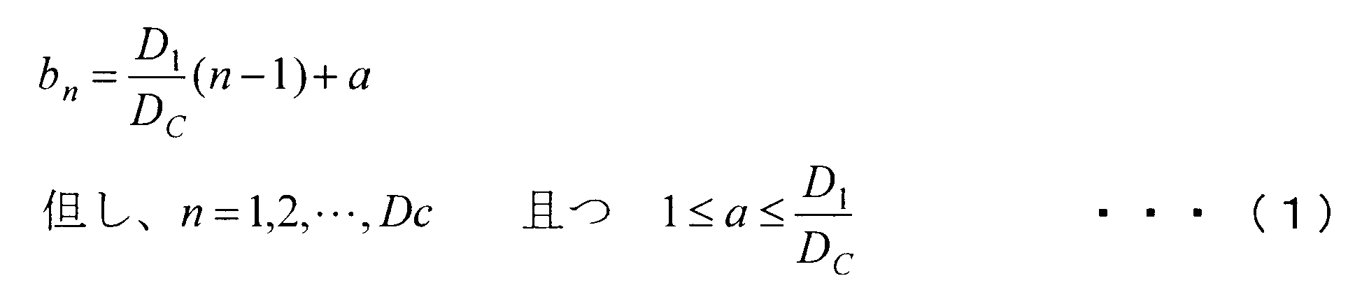
図6Aは、コピービット系列をまとめて元のビット系列中の任意の位置に配置した場合の例である。図6Bは、コピー元ビットとコピービットの位置が極力近くなるようにコピービットを配置した場合の例である。図6Cは、コピー元ビットとコピービットの位置が極力離れるようにコピービットを配置した場合の例である。
例えば、図6Aに示すように、D1=3200ビット、D2=4000ビット、及びDC=800ビットの場合、a=1とすると、1ビット目、5ビット目、9ビット目、…、3197ビット目をコピー元として選択する。
一方、D1<DCの場合、DCがD1の整数倍のとき、誤り訂正符号化されたパケット全体をコピー元ビットとして選択して、選択されたビットを(DC/D1)回コピーする。また、DCがD1の整数倍でないとき、誤り訂正符号化されたパケット全体をコピー元ビットとして選択し、選択されたビットをfloor(DC/D1)分コピーして、足りない部分(端数部分)に対してD1≧DCの場合と同様にコピー元ビットを選択して、選択されたビットをコピーする。ここで、floor(X)とは、床関数であり、実数Xに対してX以下の最大の整数を示す。
上述のように、ビット連結回路464、465が、誤り訂正符号化後のデータ長が短いパケットからコピー元ビットを選択し、コピー元ビットの情報をコピーしたコピービット(連結ビット)を当該パケット中の予め決められた位置に配置する。これにより、2つの誤り訂正符号化されたパケットのデータ長が揃えられると共に、誤り訂正符号化後のデータ長が短いパケットに対して実質的に符号化率を下げることになる。
また、コピービットの配置位置を、図6Bに示すように、コピー元ビットに隣接する位置にしてもよい。これにより、無線端末局装置30の後述する軟判定値合成回路393において、コピービットが入力されるタイミングが図6Aに比べ早くなる。その結果、軟判定値合成を開始するまでの待ち時間を短くすることができ、誤り訂正復号に係る処理遅延を短くすることが可能となる。なお、図6Aと同様に、図6BではD1=3200ビット、D2=4000ビット、DC=800ビット、a=1としている。
また、コピービットの配置位置を、図6Cに示すように、コピー元ビットとコピービットとの間に一定のビット間隔を設けた位置にしてもよい。すなわち、コピービットを1ビットずつ等間隔に配置するようにしても良い。例えば、一定のビット間隔は、データ長が短い誤り訂正符号化されたパケットのデータ長D1と、連結ビットのデータ長DCとの関係、例えば、floor(D1/DC)から算出する。これにより、図6Bに示した配置に比べると、コピー元ビットとコピービットとの相関を下げることができ、無線端末局装置30において軟判定値合成によるダイバーシチ効果を向上させることができる。なお、図6Aと同様に、図6Cでは、D1=3200ビット、D2=4000ビット、DC=800ビット、a=1としている。また、D1>D2の場合は、上記の記述のD1とD2を置き換えて考えることで対応可能である。
また、コピービット系列専用のインターリーバを用いて、コピービットにインターリーブを行って得られたビット系列を配置するようにしても良い。
なお、無線端末局装置30において、第1実施形態の無線端末局装置10(図2)と同じ構成については、同じ符号(11~16、18)を付してその説明を省略する。
パケット切出し回路391は、復調回路15より入力されたヘッダ情報に含まれる連結ビット情報に基づいて、NC復号回路18がNC復号したパケットから連結ビットを削除し、連結ビットを削除したパケットを軟判定値合成回路393に出力する。
連結ビット切出し回路392は、復調回路15より入力されたヘッダ情報に含まれる連結ビット情報に基づいて、NC復号回路18がNC復号したパケットから連結ビットを抽出し、抽出した連結ビットを軟判定値合成回路393に出力する。
誤り訂正復号回路394は、軟判定値合成回路393から入力されたパケットに対して、復調回路15から入力されたヘッダ情報に含まれる符号化率に基づいて誤り訂正復号を行い、復号されたパケットを出力する。
変調回路13は、誤り訂正符号化されたパケットAを変調して変調シンボルAに変換する。無線部14は、変調回路13が変換した変調シンボルAをアップコンバートしてRF信号Aを生成して、生成されたRF信号Aをアンテナを介して無線中継局装置40に送信する。
時刻T2において、無線端末局装置30b(ノード3)では、誤り訂正符号化回路11及び送信パケット記憶回路12に送信すべきパケットBが入力され、無線端末局装置30bは、無線端末局装置30aと同様の手順でパケットBをRF信号Bに変換して、変換されたRF信号Bを無線中継局装置40に送信する。
無線中継局装置40において、無線部21は、アンテナを介してRF信号Bを受信し、RF信号Aと同様に、復調及び誤り訂正復号により得られたパケットBをパケット記憶回路25に記憶させる(ステップS201)。
そして、データ長比較回路461は、算出したデータ長DA及びデータ長DBの差を算出し、ビット連結回路465にパケット長調整情報を出力する。このとき、パケット長調整情報には、誤り訂正符号化後のパケットA及びパケットBのデータ長の差分(100byte)を示す情報と、当該差分のデータ長の連結ビットを誤り訂正符号化したパケットBに付加する指示とが含まれている。
ビット連結回路464は、誤り訂正符号化回路462から入力された誤り訂正符号化されたパケットAをNC符号化回路27に出力する。ビット連結回路465は、データ長比較回路461から入力されたビット連結指示信号に従い、誤り訂正符号化されたパケットB(データ長DB=1400byte)から100byte長の連結ビットを生成する。更にビット連結回路465は、生成した連結ビットを誤り訂正符号化したパケットBに付加した誤り訂正符号化されたパケットB’(データ長DB’=1500byte)を生成して、生成されたパケットB’をNC符号化回路27に出力する(ステップS203)。
ビット軟判定回路16は、入力されたNCパケットCの信号に対して軟判定を行いNCパケットCの軟判定信号をNC復号回路18に出力する。
そして、レプリカパケット生成部37は、誤り訂正符号化したパケットAのデータ長DAと、入力されたNCパケットCのデータ長DC(=1500byte)とを比較して、データ長DAとデータ長DCとが等しいと判定し、誤り訂正符号化したパケットAをNC復号回路18に出力する。
パケット切出し回路391は、誤り訂正符号化されたパケットB’に含まれた連結ビットを削除して誤り訂正符号化されたパケットBを軟判定値合成回路393に出力する。連結ビット切出し回路392は、誤り訂正符号化されたパケットB’に含まれた連結ビットを切出して、切出した連結ビットを軟判定値合成回路393に出力する。
軟判定値合成回路393は、連結ビット選択ルールに従い、入力された連結ビットそれぞれを、誤り訂正符号化されたパケットBに含まれるコピー元のビットに合成して得られた誤り訂正符号化パケットBを誤り訂正復号回路394に出力する。誤り訂正復号回路394は、軟判定値合成回路393から入力された誤り訂正符号化パケットBに対して誤り訂正復号をしてパケットBを算出し、算出したパケットBを上位層などに出力する。
軟判定値合成回路393は、入力された誤り訂正符号化パケットAに対して何も合成せずに誤り訂正復号回路394に出力する、すなわち、軟判定値合成回路393は、入力された誤り訂正符号化パケットAを誤り訂正復号回路394に出力する。誤り訂正復号回路394は、軟判定値合成回路393から入力された誤り訂正符号化パケットAに対して誤り訂正復号をしてパケットAを算出し、算出したパケットAを上位層などに出力する。
また、無線中継局装置40において、ビット連結回路464、465は、パケットA及びパケットBをそれぞれに要求される符号化率で誤り訂正符号化した際にデータ長の差が生じる場合、誤り訂正符号化したパケットに含まれるビットをコピーした連結ビットを当該誤り訂正符号化したパケットに付加してデータ長を同一にするようにした。そして、無線端末局装置30a、30bにおいて、誤り訂正復号部39は、付加された連結ビットを用いて軟判定値合成を行うようにしてダイバーシチ効果を得ることにより、連結ビットを付加された誤り訂正符号化パケットの信頼性を向上させることができる。
また、64QAMを用いた場合、変調シンボルを示す3ビットの最下位ビットの誤り耐性が低いので、3ビットごとにコピー元ビットを選択して連結ビットを生成する。更に、DC>D1/3のときは、最下位ビットだけでなく、最上位ビット及び中位ビットもコピー元ビットとして選択してもよいし、最下位ビットを複数回コピーするようにしてもよい。
これにより、誤り耐性の低いビットに対して優先的に冗長性をもたせて、ダイバーシチ効果により信頼性を高めることにより、誤り訂正復号回路394における誤り訂正能力を向上させることができる。
11…誤り訂正符号化回路
12…送信パケット記憶回路
13…変調回路
14…無線部
15…復調回路
16…ビット軟判定回路
17、37…レプリカパケット生成部
18…NC復号回路
19、39…誤り訂正復号部
20、40…無線中継局装置
21…無線部
22…復調回路
23…ビット軟判定回路
24…誤り訂正復号回路
25…パケット記憶回路
26、46…誤り訂正符号化部
27…NC符号化回路
28…変調回路
91、92…無線端末局装置
93…無線中継局装置
100、200、900…無線通信システム
191…誤り訂正復号回路
261…符号化率設定回路
262、263…誤り訂正符号化回路
391…パケット切出し回路
392…連結ビット切出し回路
393…軟判定値合成回路
394…誤り訂正復号回路
461…データ長比較回路
462、463…誤り訂正符号化回路
464、465…ビット連結回路
Claims (16)
- それぞれ異なる第1パケット及び第2パケットを複数の無線端末局装置に送信する無線中継局装置であって、
前記第1パケット及び前記第2パケットそれぞれに対して要求される通信品質に応じて前記第1パケット及び前記第2パケットそれぞれに用いる符号化率を選択し、選択した符号化率を用いて前記第1パケット及び前記第2パケットそれぞれから同じデータ長の誤り訂正符号化されたパケットを生成する誤り訂正符号化部と、
誤り訂正符号化された前記第1パケット及び前記第2パケットに対してネットワーク符号化を行ってネットワーク符号化パケットを生成するネットワーク符号化回路と、
前記ネットワーク符号化パケットを前記複数の無線端末局装置に送信する送信回路と
を備える無線中継局装置。 - 前記誤り訂正符号化部は、前記第1パケット及び前記第2パケットそれぞれに対して要求される符号化率により誤り訂正符号化をした場合のパケット長を算出し、算出したパケット長が短いパケットに対応する符号化率を低くして、誤り訂正符号化された前記第1パケットと、誤り訂正符号化された前記第2パケットとが同じパケット長となる誤り訂正符号化を行う
請求項1に記載の無線中継局装置。 - 前記誤り訂正符号化部は、前記第1パケット及び前記第2パケットそれぞれを誤り訂正符号化した際にデータ長に差が生じる場合、データ長が短い誤り訂正符号化されたパケットに含まれるビットをコピーした連結ビットを生成し、該連結ビットを前記データ長が短い誤り訂正符号化されたパケットに付加して前記第1パケット及び前記第2パケットの誤り訂正符号化したデータ長を同一にする
請求項1又は請求項2に記載の無線中継局装置。 - 前記無線中継局装置から前記複数の無線端末局装置への無線伝送に直交多値変調を用いる場合、前記誤り訂正符号化部は、前記直交多値変調により生成される変調シンボルを構成するビットのうちの最下位ビットを前記連結ビットのコピー元のビットとして優先して選択する
請求項3に記載の無線中継局装置。 - 前記誤り訂正符号化部は、前記データ長が短い誤り訂正符号化されたパケット中の予め決められた位置にまとめて前記連結ビットを配置する
請求項3または請求項4に記載の無線中継局装置。 - 前記誤り訂正符号化部は、前記連結ビットを構成する各ビットのコピー元ビットの隣接した位置に該コピー元ビットからコピーした前記連結ビットを構成する各ビットを配置する
請求項3または請求項4に記載の無線中継局装置。 - 前記誤り訂正符号化部は、前記連結ビットを構成する各ビットのコピー元ビットから一定のビット間隔を隔てた位置に前記連結ビットを構成する各ビットを配置する
請求項3または請求項4に記載の無線中継局装置。 - それぞれ異なる第1パケット及び第2パケットを複数の無線端末局装置に送信する無線中継局装置を具備する無線通信システムであって、
前記無線中継局装置は、
前記第1パケット及び前記第2パケットそれぞれに対して要求される通信品質に応じて前記第1パケット及び前記第2パケットそれぞれに用いる符号化率を選択し、選択した符号化率を用いて前記第1パケット及び前記第2パケットそれぞれから同じデータ長の誤り訂正符号化されたパケットを生成する誤り訂正符号化部と、
誤り訂正符号化された前記第1パケット及び前記第2パケットに対してネットワーク符号化を行ってネットワーク符号化パケットを生成するネットワーク符号化回路と、
前記ネットワーク符号化パケットを前記複数の無線端末局装置に送信する送信回路と
を備え、
前記複数の無線端末局装置のうち、前記第1パケットと同一の第3パケットを記憶回路に記憶している無線端末局装置と、
前記複数の無線端末局装置のうち、前記第2パケットと同一の第3パケットを記憶回路に記憶している無線端末局装置それぞれは、
前記第3パケットに対して誤り訂正符号化を行う誤り訂正符号化回路と、
受信した前記ネットワーク符号化パケットを、誤り訂正符号化された前記第3パケットによりネットワーク復号して、復号パケットを生成するネットワーク復号回路と、
前記復号パケットに対して誤り訂正復号を行う誤り訂正復号部と
を備える無線通信システム。 - 前記誤り訂正符号化部は、前記第1パケット及び前記第2パケットそれぞれに対して要求される符号化率により誤り訂正符号化をした場合のパケット長を算出し、算出したパケット長が短いパケットに対応する符号化率を低くして、誤り訂正符号化された前記第1パケットと、誤り訂正符号化された前記第2パケットとが同じパケット長となる誤り訂正符号化を行う
請求項8に記載の無線通信システム。 - 前記誤り訂正符号化部は、前記第1パケット及び前記第2パケットそれぞれを誤り訂正符号化した際にデータ長に差が生じる場合、データ長が短い誤り訂正符号化されたパケットに含まれるビットをコピーした連結ビットを生成し、該連結ビットを前記データ長が短い誤り訂正符号化されたパケットに付加して前記第1パケット及び前記第2パケットの誤り訂正符号化したデータ長を同一にし、
前記誤り訂正復号部は、前記復号パケットより前記データ長が短い誤り訂正符号化されたパケット及び前記連結ビットを切出し、前記データ長が短い誤り訂正符号化されたパケットと前記連結ビットとを軟判定値合成して誤り訂正復号する
請求項8又は請求項9に記載の無線通信システム。 - 前記無線中継局装置から前記複数の無線端末局装置への無線伝送に直交多値変調を用いる場合、前記誤り訂正符号化部は、前記直交多値変調により生成される変調シンボルを構成するビットのうちの最下位ビットを前記連結ビットのコピー元のビットとして優先して選択する
請求項10に記載の無線通信システム。 - 前記誤り訂正符号化部は、前記データ長が短い誤り訂正符号化されたパケット中の予め決められた位置にまとめて前記連結ビットを配置する
請求項10または請求項11に記載の無線通信システム。 - 前記誤り訂正符号化部は、前記連結ビットを構成する各ビットのコピー元ビットの隣接した位置に該コピー元ビットからコピーした前記連結ビットを構成する各ビットを配置する
請求項10または請求項11に記載の無線通信システム。 - 前記誤り訂正符号化部は、前記連結ビットを構成する各ビットのコピー元ビットから一定のビット間隔を隔てた位置に前記連結ビットを構成する各ビットを配置する
請求項10または請求項11に記載の無線通信システム。 - それぞれ異なる第1パケット及び第2パケットを複数の無線端末局装置に送信する無線中継局装置を具備する無線通信システムにおける無線端末局装置であって、
前記無線中継局装置が、前記第1パケット及び前記第2パケットそれぞれに対して要求される通信品質に応じて前記第1パケット及び前記第2パケットそれぞれに用いる符号化率を選択し、選択した符号化率を用いて前記第1パケット及び前記第2パケットそれぞれから同じデータ長の誤り訂正符号化されたパケットを生成し、誤り訂正符号化された前記第1パケット及び前記第2パケットに対してネットワーク符号化を行い生成したネットワーク符号化パケットを受信する受信回路と、
前記第1パケット又は前記第2パケットのいずれか一方と同一の第3パケットを記憶している記憶回路と、
前記第3パケットに対して誤り訂正符号化を行う誤り訂正符号化回路と、
受信した前記ネットワーク符号化パケットを、誤り訂正符号化された前記第3パケットによりネットワーク復号して、復号パケットを生成するネットワーク復号回路と、
前記復号パケットに対して誤り訂正復号を行う誤り訂正復号部と
を備える無線端末局装置。 - それぞれ異なる第1パケット及び第2パケットを複数の無線端末局装置に送信する無線中継局装置を具備する無線通信システムにおける無線通信方法であって、
前記無線中継局装置の誤り訂正符号化部が、前記第1パケット及び前記第2パケットそれぞれに対して要求される通信品質に応じて前記第1パケット及び前記第2パケットそれぞれに用いる符号化率を選択し、選択した符号化率を用いて前記第1パケット及び前記第2パケットそれぞれから同じデータ長の誤り訂正符号化されたパケットを生成する過程と、
前記無線中継局装置のネットワーク符号化回路が、誤り訂正符号化された前記第1パケット及び前記第2パケットに対してネットワーク符号化を行ってネットワーク符号化パケットを生成する過程と、
前記無線中継局装置の送信回路が、前記ネットワーク符号化パケットを前記複数の無線端末局装置に送信する過程と、
前記複数の無線端末局装置のうち、前記第1パケットと同一の第3パケットを記憶回路に記憶している無線端末局装置の誤り訂正符号化回路が、記憶されている前記第3パケットに対して誤り訂正符号化を行う過程と、
前記複数の無線端末局装置のうち、前記第2パケットと同一の第3パケットを記憶回路に記憶している無線端末局装置の誤り訂正符号化回路が、記憶されている前記第3パケットに対して誤り訂正符号化を行う過程と、
前記複数の無線端末局装置のネットワーク復号回路が、受信した前記ネットワーク符号化パケットを、誤り訂正符号化された前記第3パケットによりネットワーク復号して、復号パケットを生成する過程と、
前記複数の無線端末局装置の誤り訂正復号部が、前記復号パケットに対して誤り訂正復号を行う過程と
を備える無線通信方法。
Priority Applications (6)
| Application Number | Priority Date | Filing Date | Title |
|---|---|---|---|
| JP2011535356A JPWO2011043230A1 (ja) | 2009-10-07 | 2010-09-29 | 無線通信システム、無線中継局装置、無線端末局装置、及び無線通信方法 |
| KR1020147004309A KR20140032013A (ko) | 2009-10-07 | 2010-09-29 | 무선 통신 시스템, 무선 중계국 장치, 무선 단말국 장치 및 무선 통신 방법 |
| US13/498,968 US8914714B2 (en) | 2009-10-07 | 2010-09-29 | Wireless communication system, wireless relay station apparatus, wireless terminal station apparatus, and wireless communication method |
| EP10821901.5A EP2487808B1 (en) | 2009-10-07 | 2010-09-29 | Wireless communication system, radio relay station apparatus, radio terminal station apparatus, and wireless communication method |
| KR1020127008400A KR101404724B1 (ko) | 2009-10-07 | 2010-09-29 | 무선 통신 시스템, 무선 중계국 장치, 무선 단말국 장치 및 무선 통신 방법 |
| CN201080043992.6A CN102577167B (zh) | 2009-10-07 | 2010-09-29 | 无线通信系统、无线中继站装置、无线终端站装置以及无线通信方法 |
Applications Claiming Priority (2)
| Application Number | Priority Date | Filing Date | Title |
|---|---|---|---|
| JP2009-233740 | 2009-10-07 | ||
| JP2009233740 | 2009-10-07 |
Publications (1)
| Publication Number | Publication Date |
|---|---|
| WO2011043230A1 true WO2011043230A1 (ja) | 2011-04-14 |
Family
ID=43856688
Family Applications (1)
| Application Number | Title | Priority Date | Filing Date |
|---|---|---|---|
| PCT/JP2010/066899 Ceased WO2011043230A1 (ja) | 2009-10-07 | 2010-09-29 | 無線通信システム、無線中継局装置、無線端末局装置、及び無線通信方法 |
Country Status (6)
| Country | Link |
|---|---|
| US (1) | US8914714B2 (ja) |
| EP (1) | EP2487808B1 (ja) |
| JP (1) | JPWO2011043230A1 (ja) |
| KR (2) | KR101404724B1 (ja) |
| CN (1) | CN102577167B (ja) |
| WO (1) | WO2011043230A1 (ja) |
Cited By (4)
| Publication number | Priority date | Publication date | Assignee | Title |
|---|---|---|---|---|
| CN102237967A (zh) * | 2011-07-29 | 2011-11-09 | 中兴通讯股份有限公司 | 一种网络编码的数据块处理方法及其装置 |
| JP2013141061A (ja) * | 2011-12-28 | 2013-07-18 | Mitsubishi Electric Corp | 衛星中継装置および衛星通信システム |
| JP2014192607A (ja) * | 2013-03-26 | 2014-10-06 | Nippon Telegr & Teleph Corp <Ntt> | 無線通信方法及び無線通信装置 |
| WO2023238205A1 (ja) * | 2022-06-06 | 2023-12-14 | 日本電信電話株式会社 | 通信装置、通信方法、及びプログラム |
Families Citing this family (8)
| Publication number | Priority date | Publication date | Assignee | Title |
|---|---|---|---|---|
| US8503346B2 (en) * | 2008-09-25 | 2013-08-06 | Samsung Electronics Co., Ltd. | Wireless network using network coding scheme based on overhearing channel |
| WO2014077533A1 (en) * | 2012-11-14 | 2014-05-22 | Samsung Electronics Co., Ltd. | Base station and a plurality of member nodes for transmitting and receiving network coding based multicast traffic |
| KR102095493B1 (ko) * | 2014-01-16 | 2020-04-16 | 삼성전자주식회사 | 무선 멀티홉 통신을 위한 신호 전달 방법 및 장치 |
| CN105471545B (zh) * | 2014-09-10 | 2020-07-21 | 中兴通讯股份有限公司 | 一种数据包处理方法及装置 |
| CN106332287B (zh) * | 2015-07-01 | 2022-03-18 | 西安中兴新软件有限责任公司 | 一种数据传输方法及通信节点 |
| US10517092B1 (en) | 2018-06-04 | 2019-12-24 | SparkMeter, Inc. | Wireless mesh data network with increased transmission capacity |
| US12438957B1 (en) * | 2021-09-21 | 2025-10-07 | Graphiant, Inc. | Method and system for IP header compression |
| CN115835311B (zh) * | 2022-11-14 | 2025-12-23 | 中国联合网络通信集团有限公司 | 码率配置方法、装置、及存储介质 |
Citations (7)
| Publication number | Priority date | Publication date | Assignee | Title |
|---|---|---|---|---|
| WO2007020996A1 (ja) * | 2005-08-19 | 2007-02-22 | Matsushita Electric Industrial Co., Ltd. | 無線通信装置および無線通信方法 |
| US20070184826A1 (en) * | 2006-01-09 | 2007-08-09 | Samsung Electronics Co., Ltd. | Method for relaying in a cellular network and cellular mobile communication system supporting the same |
| WO2009066451A1 (ja) * | 2007-11-21 | 2009-05-28 | Panasonic Corporation | 無線通信装置、無線通信方法および無線通信システム |
| WO2009069262A1 (ja) * | 2007-11-29 | 2009-06-04 | Panasonic Corporation | 無線送信装置および無線送信方法 |
| JP2009135928A (ja) * | 2007-11-30 | 2009-06-18 | Ntt Docomo Inc | マルチホップリレーシステムの双方向データ伝送処理方法及び中間装置 |
| JP2009225063A (ja) * | 2008-03-14 | 2009-10-01 | Fujitsu Ltd | データ中継装置、通信装置およびデータ中継方法 |
| JP2009233740A (ja) | 2008-03-28 | 2009-10-15 | Nippon Carbide Ind Co Inc | 可締め冶具 |
Family Cites Families (9)
| Publication number | Priority date | Publication date | Assignee | Title |
|---|---|---|---|---|
| US7570645B2 (en) * | 2000-01-18 | 2009-08-04 | Viasat, Inc. | Frame format and frame assembling/disassembling method for the frame format |
| SE0403218D0 (sv) * | 2004-12-30 | 2004-12-30 | Ericsson Telefon Ab L M | Method and apparatus relating to communication- |
| US7177804B2 (en) * | 2005-05-31 | 2007-02-13 | Microsoft Corporation | Sub-band voice codec with multi-stage codebooks and redundant coding |
| CN101248604A (zh) * | 2005-08-19 | 2008-08-20 | 松下电器产业株式会社 | 无线通信装置以及无线通信方法 |
| US20090305690A1 (en) * | 2006-03-01 | 2009-12-10 | Matsushita Electric Industrial Co., Ltd | Radio transmission device and radio transmission method |
| JP2008028656A (ja) * | 2006-07-20 | 2008-02-07 | Shinshu Univ | 適応制御型ダイバーシチ通信システム |
| WO2009057183A1 (ja) * | 2007-11-02 | 2009-05-07 | Fujitsu Limited | ネットワーク符号化方法およびネットワーク符号化装置 |
| US8255753B2 (en) * | 2007-12-04 | 2012-08-28 | Intel Corporation | Encoding/decoding technique for rebroadcasting lost packets |
| US8306095B2 (en) * | 2008-04-29 | 2012-11-06 | Samsung Electronics Co., Ltd. | Methods and apparatus for network coding in a communication system |
-
2010
- 2010-09-29 JP JP2011535356A patent/JPWO2011043230A1/ja active Pending
- 2010-09-29 WO PCT/JP2010/066899 patent/WO2011043230A1/ja not_active Ceased
- 2010-09-29 EP EP10821901.5A patent/EP2487808B1/en active Active
- 2010-09-29 KR KR1020127008400A patent/KR101404724B1/ko active Active
- 2010-09-29 US US13/498,968 patent/US8914714B2/en active Active
- 2010-09-29 CN CN201080043992.6A patent/CN102577167B/zh active Active
- 2010-09-29 KR KR1020147004309A patent/KR20140032013A/ko not_active Ceased
Patent Citations (7)
| Publication number | Priority date | Publication date | Assignee | Title |
|---|---|---|---|---|
| WO2007020996A1 (ja) * | 2005-08-19 | 2007-02-22 | Matsushita Electric Industrial Co., Ltd. | 無線通信装置および無線通信方法 |
| US20070184826A1 (en) * | 2006-01-09 | 2007-08-09 | Samsung Electronics Co., Ltd. | Method for relaying in a cellular network and cellular mobile communication system supporting the same |
| WO2009066451A1 (ja) * | 2007-11-21 | 2009-05-28 | Panasonic Corporation | 無線通信装置、無線通信方法および無線通信システム |
| WO2009069262A1 (ja) * | 2007-11-29 | 2009-06-04 | Panasonic Corporation | 無線送信装置および無線送信方法 |
| JP2009135928A (ja) * | 2007-11-30 | 2009-06-18 | Ntt Docomo Inc | マルチホップリレーシステムの双方向データ伝送処理方法及び中間装置 |
| JP2009225063A (ja) * | 2008-03-14 | 2009-10-01 | Fujitsu Ltd | データ中継装置、通信装置およびデータ中継方法 |
| JP2009233740A (ja) | 2008-03-28 | 2009-10-15 | Nippon Carbide Ind Co Inc | 可締め冶具 |
Non-Patent Citations (2)
| Title |
|---|
| R. AHLSWEDE; N. CAI; S. LI; R. YEUNG: "Network information flow", IEEE TRANS. INF. THEORY, vol. 46, no. 4, July 2000 (2000-07-01), pages 1204 - 1216, XP011027651 |
| SACHIN KATTI; HARIHARAN RAHUL ET AL.: "XORs in The Air: Practical Wireless Network Coding", PROC. ACM SIGCOMM, September 2006 (2006-09-01), pages 243 - 254 |
Cited By (5)
| Publication number | Priority date | Publication date | Assignee | Title |
|---|---|---|---|---|
| CN102237967A (zh) * | 2011-07-29 | 2011-11-09 | 中兴通讯股份有限公司 | 一种网络编码的数据块处理方法及其装置 |
| JP2013141061A (ja) * | 2011-12-28 | 2013-07-18 | Mitsubishi Electric Corp | 衛星中継装置および衛星通信システム |
| JP2014192607A (ja) * | 2013-03-26 | 2014-10-06 | Nippon Telegr & Teleph Corp <Ntt> | 無線通信方法及び無線通信装置 |
| WO2023238205A1 (ja) * | 2022-06-06 | 2023-12-14 | 日本電信電話株式会社 | 通信装置、通信方法、及びプログラム |
| JPWO2023238205A1 (ja) * | 2022-06-06 | 2023-12-14 |
Also Published As
| Publication number | Publication date |
|---|---|
| EP2487808A4 (en) | 2017-08-09 |
| CN102577167A (zh) | 2012-07-11 |
| US20120239997A1 (en) | 2012-09-20 |
| EP2487808A1 (en) | 2012-08-15 |
| JPWO2011043230A1 (ja) | 2013-03-04 |
| US8914714B2 (en) | 2014-12-16 |
| CN102577167B (zh) | 2014-12-10 |
| KR20120063502A (ko) | 2012-06-15 |
| EP2487808B1 (en) | 2018-11-14 |
| KR20140032013A (ko) | 2014-03-13 |
| KR101404724B1 (ko) | 2014-06-09 |
Similar Documents
| Publication | Publication Date | Title |
|---|---|---|
| KR101404724B1 (ko) | 무선 통신 시스템, 무선 중계국 장치, 무선 단말국 장치 및 무선 통신 방법 | |
| US11121761B2 (en) | System and method for multiuser packets transmissions for relays | |
| JP3910770B2 (ja) | 誤り制御方法及びその方法を使用する受信機 | |
| TWI404363B (zh) | 無線通信系統中用於雙向中繼之方法及配置 | |
| KR101281252B1 (ko) | 멀티 홉 무선 통신 시스템들 내에서 협력 중계를 위한 방법 | |
| US9001776B2 (en) | Method and apparatus for transmitting/receiving control information in a wireless communication system | |
| KR101050923B1 (ko) | 데이터 중계 장치, 통신 장치 및 데이터 중계 방법 | |
| CN106464340B (zh) | 用于为不同用户正交地中继用户数据的方法 | |
| JPWO2009057183A1 (ja) | ネットワーク符号化方法およびネットワーク符号化装置 | |
| CN101971672A (zh) | 网络登录与恢复 | |
| JPWO2009066451A1 (ja) | 無線通信装置、無線通信方法および無線通信システム | |
| WO2020166230A1 (ja) | 通信装置及び通信方法 | |
| WO2020166229A1 (ja) | 通信装置及び通信方法 | |
| JP5158213B2 (ja) | 無線通信システム、基地局、移動局、無線通信方法 | |
| JP5415227B2 (ja) | ブロックフェージングチャネルの分散ターボ符号器 | |
| Lin | Design of network coding schemes in wireless networks | |
| JP2008193240A (ja) | 無線通信装置および無線通信方法 | |
| US9455798B2 (en) | Forward error correction (FEC) to support successive interference cancellation (SIC) | |
| JP5084690B2 (ja) | 無線中継システム、無線中継方法、中継局、及び送受信局 | |
| JP4943389B2 (ja) | 無線通信システム、受信端末、無線通信方法及び受信方法 | |
| JP6737951B2 (ja) | 無線通信システム | |
| JP5025705B2 (ja) | 無線中継システム、中継局装置、端末局装置、及び、無線中継方法 | |
| KR101088687B1 (ko) | 릴레이 네트워크에서 데이터 중계장치 및 방법 | |
| CN121666713A (zh) | 对可自解码有效载荷和组合有效载荷进行联合纠错编解码的方法、系统和装置 | |
| HK1229553B (zh) | 用於为不同用户正交地中继用户数据的方法 |
Legal Events
| Date | Code | Title | Description |
|---|---|---|---|
| WWE | Wipo information: entry into national phase |
Ref document number: 201080043992.6 Country of ref document: CN |
|
| 121 | Ep: the epo has been informed by wipo that ep was designated in this application |
Ref document number: 10821901 Country of ref document: EP Kind code of ref document: A1 |
|
| WWE | Wipo information: entry into national phase |
Ref document number: 2011535356 Country of ref document: JP |
|
| ENP | Entry into the national phase |
Ref document number: 20127008400 Country of ref document: KR Kind code of ref document: A |
|
| WWE | Wipo information: entry into national phase |
Ref document number: 2010821901 Country of ref document: EP |
|
| NENP | Non-entry into the national phase |
Ref country code: DE |
|
| WWE | Wipo information: entry into national phase |
Ref document number: 13498968 Country of ref document: US |