WO2011043433A1 - フレームレート変換装置及び方法 - Google Patents
フレームレート変換装置及び方法 Download PDFInfo
- Publication number
- WO2011043433A1 WO2011043433A1 PCT/JP2010/067674 JP2010067674W WO2011043433A1 WO 2011043433 A1 WO2011043433 A1 WO 2011043433A1 JP 2010067674 W JP2010067674 W JP 2010067674W WO 2011043433 A1 WO2011043433 A1 WO 2011043433A1
- Authority
- WO
- WIPO (PCT)
- Prior art keywords
- pixel data
- interpolation
- frame
- correlation
- motion vector
- Prior art date
- Legal status (The legal status is an assumption and is not a legal conclusion. Google has not performed a legal analysis and makes no representation as to the accuracy of the status listed.)
- Ceased
Links
Images



Classifications
-
- H—ELECTRICITY
- H04—ELECTRIC COMMUNICATION TECHNIQUE
- H04N—PICTORIAL COMMUNICATION, e.g. TELEVISION
- H04N7/00—Television systems
- H04N7/01—Conversion of standards, e.g. involving analogue television standards or digital television standards processed at pixel level
-
- H—ELECTRICITY
- H04—ELECTRIC COMMUNICATION TECHNIQUE
- H04N—PICTORIAL COMMUNICATION, e.g. TELEVISION
- H04N7/00—Television systems
- H04N7/01—Conversion of standards, e.g. involving analogue television standards or digital television standards processed at pixel level
- H04N7/0127—Conversion of standards, e.g. involving analogue television standards or digital television standards processed at pixel level by changing the field or frame frequency of the incoming video signal, e.g. frame rate converter
- H04N7/0132—Conversion of standards, e.g. involving analogue television standards or digital television standards processed at pixel level by changing the field or frame frequency of the incoming video signal, e.g. frame rate converter the field or frame frequency of the incoming video signal being multiplied by a positive integer, e.g. for flicker reduction
-
- G—PHYSICS
- G06—COMPUTING OR CALCULATING; COUNTING
- G06T—IMAGE DATA PROCESSING OR GENERATION, IN GENERAL
- G06T3/00—Geometric image transformations in the plane of the image
- G06T3/40—Scaling of whole images or parts thereof, e.g. expanding or contracting
- G06T3/4007—Scaling of whole images or parts thereof, e.g. expanding or contracting based on interpolation, e.g. bilinear interpolation
-
- G—PHYSICS
- G06—COMPUTING OR CALCULATING; COUNTING
- G06T—IMAGE DATA PROCESSING OR GENERATION, IN GENERAL
- G06T7/00—Image analysis
- G06T7/20—Analysis of motion
-
- H—ELECTRICITY
- H04—ELECTRIC COMMUNICATION TECHNIQUE
- H04N—PICTORIAL COMMUNICATION, e.g. TELEVISION
- H04N19/00—Methods or arrangements for coding, decoding, compressing or decompressing digital video signals
- H04N19/10—Methods or arrangements for coding, decoding, compressing or decompressing digital video signals using adaptive coding
- H04N19/102—Methods or arrangements for coding, decoding, compressing or decompressing digital video signals using adaptive coding characterised by the element, parameter or selection affected or controlled by the adaptive coding
- H04N19/132—Sampling, masking or truncation of coding units, e.g. adaptive resampling, frame skipping, frame interpolation or high-frequency transform coefficient masking
-
- H—ELECTRICITY
- H04—ELECTRIC COMMUNICATION TECHNIQUE
- H04N—PICTORIAL COMMUNICATION, e.g. TELEVISION
- H04N19/00—Methods or arrangements for coding, decoding, compressing or decompressing digital video signals
- H04N19/10—Methods or arrangements for coding, decoding, compressing or decompressing digital video signals using adaptive coding
- H04N19/134—Methods or arrangements for coding, decoding, compressing or decompressing digital video signals using adaptive coding characterised by the element, parameter or criterion affecting or controlling the adaptive coding
- H04N19/136—Incoming video signal characteristics or properties
- H04N19/137—Motion inside a coding unit, e.g. average field, frame or block difference
- H04N19/139—Analysis of motion vectors, e.g. their magnitude, direction, variance or reliability
-
- H—ELECTRICITY
- H04—ELECTRIC COMMUNICATION TECHNIQUE
- H04N—PICTORIAL COMMUNICATION, e.g. TELEVISION
- H04N19/00—Methods or arrangements for coding, decoding, compressing or decompressing digital video signals
- H04N19/10—Methods or arrangements for coding, decoding, compressing or decompressing digital video signals using adaptive coding
- H04N19/169—Methods or arrangements for coding, decoding, compressing or decompressing digital video signals using adaptive coding characterised by the coding unit, i.e. the structural portion or semantic portion of the video signal being the object or the subject of the adaptive coding
- H04N19/17—Methods or arrangements for coding, decoding, compressing or decompressing digital video signals using adaptive coding characterised by the coding unit, i.e. the structural portion or semantic portion of the video signal being the object or the subject of the adaptive coding the unit being an image region, e.g. an object
- H04N19/172—Methods or arrangements for coding, decoding, compressing or decompressing digital video signals using adaptive coding characterised by the coding unit, i.e. the structural portion or semantic portion of the video signal being the object or the subject of the adaptive coding the unit being an image region, e.g. an object the region being a picture, frame or field
-
- H—ELECTRICITY
- H04—ELECTRIC COMMUNICATION TECHNIQUE
- H04N—PICTORIAL COMMUNICATION, e.g. TELEVISION
- H04N19/00—Methods or arrangements for coding, decoding, compressing or decompressing digital video signals
- H04N19/10—Methods or arrangements for coding, decoding, compressing or decompressing digital video signals using adaptive coding
- H04N19/169—Methods or arrangements for coding, decoding, compressing or decompressing digital video signals using adaptive coding characterised by the coding unit, i.e. the structural portion or semantic portion of the video signal being the object or the subject of the adaptive coding
- H04N19/17—Methods or arrangements for coding, decoding, compressing or decompressing digital video signals using adaptive coding characterised by the coding unit, i.e. the structural portion or semantic portion of the video signal being the object or the subject of the adaptive coding the unit being an image region, e.g. an object
- H04N19/176—Methods or arrangements for coding, decoding, compressing or decompressing digital video signals using adaptive coding characterised by the coding unit, i.e. the structural portion or semantic portion of the video signal being the object or the subject of the adaptive coding the unit being an image region, e.g. an object the region being a block, e.g. a macroblock
-
- H—ELECTRICITY
- H04—ELECTRIC COMMUNICATION TECHNIQUE
- H04N—PICTORIAL COMMUNICATION, e.g. TELEVISION
- H04N19/00—Methods or arrangements for coding, decoding, compressing or decompressing digital video signals
- H04N19/50—Methods or arrangements for coding, decoding, compressing or decompressing digital video signals using predictive coding
- H04N19/587—Methods or arrangements for coding, decoding, compressing or decompressing digital video signals using predictive coding involving temporal sub-sampling or interpolation, e.g. decimation or subsequent interpolation of pictures in a video sequence
-
- H—ELECTRICITY
- H04—ELECTRIC COMMUNICATION TECHNIQUE
- H04N—PICTORIAL COMMUNICATION, e.g. TELEVISION
- H04N7/00—Television systems
- H04N7/01—Conversion of standards, e.g. involving analogue television standards or digital television standards processed at pixel level
- H04N7/0135—Conversion of standards, e.g. involving analogue television standards or digital television standards processed at pixel level involving interpolation processes
- H04N7/014—Conversion of standards, e.g. involving analogue television standards or digital television standards processed at pixel level involving interpolation processes involving the use of motion vectors
Definitions
- the present invention relates to a frame rate conversion apparatus and method for generating an interpolation pixel using a motion vector of a moving image and interpolating the interpolation frame between actual frames to convert a frame rate.
- an interpolation frame is interpolated between real frames of the video signal to increase the number of frames, for example, a frame rate of 60 Hz of vertical frequency is converted to a vertical frequency of 120 Hz or more which is doubled. It is done to display.
- a motion vector of an image is detected, each interpolation pixel is generated using the motion vector, and an interpolation frame to be interpolated between real frames is generated.
- Patent Document 1 An example of a motion compensated frame rate conversion apparatus that generates an interpolation pixel using a motion vector and interpolates an interpolation frame between actual frames to convert the frame rate is described in Patent Document 1 as an example.
- erroneous interpolation may occur to generate an erroneous image.
- erroneous interpolation is likely to occur.
- false detection of a motion vector easily occurs near the boundary between the foreground and the background, and an interpolation image having an unnatural and strange feeling is generated due to the false interpolation.
- the present invention has been made in view of such problems, and it is an object of the present invention to provide a frame rate conversion apparatus and method capable of reducing erroneous interpolation caused by erroneous detection of a motion vector.
- the present invention is pixel data on a first frame in order to solve the problems of the prior art described above, and is provided between the first frame and a second frame past the first frame.
- a second pixel data at the same position as the interpolation pixel data, and a plurality of pixel data on the first frame.
- the second maximum correlation value having the largest correlation and the direction indicating the second maximum correlation value are Among the first motion vector and the second motion vector
- the second correlation comparison unit (24) that outputs the motion vector as the motion vector, among the first maximum correlation value and the second maximum correlation value
- a third correlation comparing unit (25) that outputs the motion vector having the larger correlation as a final third motion vector, and a plurality of the first motion vector based on the third motion vector.
- a first pixel data selection unit (31) which selects and outputs third pixel data necessary for generating the interpolation pixel data among pixel data, and the third motion vector based on the third motion vector.
- a frame rate conversion unit (4) that generates the interpolation frame using the interpolation pixel data and interpolates between the first frame and the second frame to convert the frame rate.
- the present invention provides a frame rate conversion apparatus characterized by
- the third correlation comparison unit when the difference between the first motion vector and the second motion vector satisfies a first condition in which a difference between the first motion vector and the second motion vector satisfies a first condition, the third correlation comparison unit generates the interpolation pixel data generation unit Outputting a determination signal for making the interpolation at both sides interpolation, and the interpolation pixel data generation unit, when the determination signal is input, averages the third and fourth pixel data and outputs the interpolation pixel data It is preferred to generate.
- the third correlation comparison unit may be configured such that the difference between the first motion vector and the second motion vector is within a predetermined range, and the first maximum correlation value and the second maximum correlation value Outputting a determination signal for making the interpolation in the interpolation pixel data generation unit be a two-sided interpolation, when the absolute value of the difference between Preferably, the interpolation pixel data generation unit generates the interpolation pixel data by averaging the third and fourth pixel data when the determination signal is input.
- the third correlation comparison unit is a value in which an absolute value of a difference between the first maximum correlation value and the second maximum correlation value is smaller than the first threshold. It is preferable to output a determination signal for making the interpolation in the interpolation pixel data generation unit be a two-sided interpolation also when the third condition smaller than the second threshold which is the second condition is satisfied.
- the present invention is pixel data on a first frame, and is between the first frame and a second frame past the first frame.
- the second maximum correlation value having the largest correlation and the direction indicating the second maximum correlation value are
- a second pixel data selection step of selecting and outputting the fourth pixel data necessary to generate the interpolation pixel data, one-side interpolation using only the third pixel data, and the fourth pixel An interpolated pixel data generation step of generating and outputting the interpolated pixel data by selecting one of single-sided interpolation using only data and double-sided interpolation using the third and fourth pixel data;
- a frame rate conversion step of generating the interpolation frame using interpolation pixel data and converting the frame rate by interpolation between the first frame and the second frame. Provide a conversion method.
- the interpolated pixel data generation step is performed when the difference between the first motion vector and the second motion vector satisfies a first condition that is within a predetermined range.
- Outputting a determination signal for making the interpolation at both sides interpolation, and the interpolation pixel data generation step averages the third and fourth pixel data to input the interpolation pixel data when the determination signal is input. It is preferred to generate.
- the difference between the first motion vector and the second motion vector is within a predetermined range
- the first maximum correlation value and the second maximum correlation value Outputting a determination signal for making the interpolation in the interpolation pixel data generation step be a two-sided interpolation when the absolute value of the difference between the two and the first condition is smaller than the first threshold value, and the interpolation pixel data generation step
- the third and fourth pixel data are averaged to generate the interpolated pixel data.
- the absolute value of the difference between the first maximum correlation value and the second maximum correlation value is a value smaller than the first threshold. Also when the third condition smaller than the second threshold value is satisfied, it is preferable to output a determination signal for making the interpolation in the interpolation pixel data generation step be a two-sided interpolation.
- the frame rate conversion apparatus and method of the present invention it is possible to reduce erroneous interpolation caused by erroneous detection of a motion vector, so it is possible to obtain a frame rate converted image that is natural and less uncomfortable.
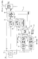
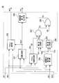
- FIG. 1 is a block diagram showing an embodiment of a frame rate conversion apparatus of the present invention.
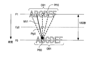
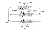
- FIG. 2 is a diagram for explaining a first correlation detection method used in one embodiment.
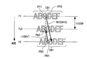
- FIG. 3 is a diagram for explaining a second correlation detection method used in one embodiment.
- FIG. 4 is a diagram for explaining an interpolation vector based on a motion vector.
- FIG. 5 is a block diagram showing an example of a specific configuration of the correlation comparing unit 25 in FIG.
- FIG. 6 is a diagram for explaining the operation of the correlation comparing unit 25 shown in FIG.
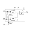
- FIG. 7 is a block diagram showing a specific configuration example of the selection and averaging unit 34 in FIG.
- FIG. 8 is a diagram for explaining the interpolation operation in one embodiment.
- FIG. 9 is a diagram for explaining the interpolation operation in one embodiment.
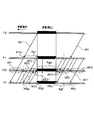
- FIG. 10 is a diagram for explaining the effect of the embodiment.
- each pixel data of a video signal Sin having a frame frequency of 60 Hz is sequentially input to a frame memory 1, a motion vector detection unit 2, an interpolation unit 3, and a time series conversion memory 4.
- the frame memory 1 delays the input pixel data by one frame and outputs it.
- a current frame of the input video signal Sin is F0, and a frame one frame before the current frame output from the frame memory 1 is F1.
- the pixel data of the frame F1 is sequentially input to the motion vector detection unit 2 and the interpolation unit 3.
- the motion vector detection unit 2 includes correlation detection units 21 and 22 and correlation comparison units 23 to 25.
- the correlation detection unit 21 detects the correlation in a plurality of directions by the first correlation detection method shown in FIG.
- the first correlation detection method performed by the correlation detection unit 21 will be described with reference to FIG.
- FIG. 2 shows a state in which an object OB1 formed of a character image "ABCDEF" is horizontally moved in the adjacent frames F1 and F0.
- the frame Fp0 is an interpolation frame to be interpolated between the frames F1 and F0.
- difference values in a plurality of directions are generated as shown in FIG. Strictly speaking, the difference value is the difference absolute value of the luminance value of the pixel data, and hereinafter, it will be simply referred to as the difference value.
- pixel data Pf00 on frame F0 located at the same horizontal and vertical position as interpolated pixel data Pfp0 is fixed as pixel data after movement, and a plurality of pixel data on frame F1 is made with pixel data before movement.
- the pixel data before movement on the frame F1 is pixel data within a predetermined range centered on the pixel data Pf10 at the same horizontal and vertical positions as the interpolated pixel data Pfp0. Note that, for simplification, only the pixel data Pf10 on the frame F1 is indicated by a circle, and the circles of other pixel data are omitted.
- the correlation detection unit 21 obtains difference values Df11 to Df1M between the pixel data Pf00 and the plurality of pixel data in the frame F1. As shown in FIG. 1, the difference values Df11 to Df1M are input to the correlation comparison unit 23.
- the difference values Df11 to Df1M can also be referred to as correlation values. The smaller the difference value, the larger the correlation, and the larger the difference value, the smaller the correlation.
- the correlation comparison unit 23 compares the difference values Df11 to Df1M and outputs the direction indicating the smallest value as the motion vector MV1 and outputs the smallest difference value, that is, the difference value of the motion vector MV1 as the DF1. .
- the direction having the smallest difference value DF1 has the largest correlation.
- the smallest difference value DF1 is the maximum correlation value.
- broken lines connecting the pixel data Pf00 and each of a plurality of pixel data on the frame F1 indicate candidate vectors not selected as the motion vector MV1.
- the motion vector MV1 and the difference value DF1 output from the correlation comparison unit 23 are supplied to the correlation comparison unit 25.
- the correlation detection unit 22 detects the correlation in a plurality of directions by the second correlation detection method shown in FIG.
- the second correlation detection method performed by the correlation detection unit 22 will be described with reference to FIG. Similar to FIG. 2, FIG. 3 shows a state in which the object OB1 formed of a character image of “ABCDEF” is horizontally moved in the adjacent frames F1 and F0.
- FIG. 3 shows a state in which the object OB1 formed of a character image of “ABCDEF” is horizontally moved in the adjacent frames F1 and F0.
- differential values in a plurality of directions are generated as shown in FIG.
- pixel data Pf10 on frame F1 at the same horizontal and vertical position as interpolated pixel data Pfp0 is fixed as pixel data before movement, and a plurality of pixel data on frame F0 is after pixel data after movement.
- the pixel data after movement on the frame F0 is pixel data within a predetermined range centered on the pixel data Pf00 located at the same horizontal and vertical positions as the interpolated pixel data Pfp0. Note that, for simplification, only the pixel data Pf00 on the frame F0 is indicated by a circle, and the circle of the other pixel data is omitted.
- the correlation detection unit 22 obtains difference values Df21 to Df2M between the pixel data Pf10 and a plurality of pixel data on the frame F0. As shown in FIG. 1, the difference values Df21 to Df2M are input to the correlation comparison unit 24. Similarly, the difference values Df21 to Df2M can also be referred to as correlation values.
- the correlation comparison unit 24 compares the difference values Df21 to Df2M and outputs the direction indicating the smallest value as the motion vector MV2, and the smallest difference value (maximum correlation value), that is, the difference value of the motion vector MV2 Is output as DF2.
- broken lines connecting the pixel data Pf10 and a plurality of pixel data on the frame F0 indicate candidate vectors not selected as the motion vector MV2.
- the motion vector MV2 and the difference value DF2 output from the correlation comparison unit 24 are supplied to the correlation comparison unit 25.
- the correlation value is detected by obtaining the difference value between a pair of pixel data, but based on the sum of absolute differences obtained by calculating and integrating the difference value for each block including a plurality of pixel data.
- a correlation may be determined.
- the detection method of correlation is arbitrary.
- the correlation comparison unit 25 generates and outputs a final motion vector MV3 and an interpolation control signal FS1 for determining an interpolation method in the interpolation unit 3 based on the difference values DF1 and DF2 and the motion vectors MV1 and MV2. Do.
- motion vector MV3 is the vector shown in FIG. 4
- a pair of interpolation vectors for generating interpolation pixel data Pfp0 is a vector (1/2) ⁇ directed from pixel data Pf11 on frame F1 to interpolation pixel data Pfp0.
- MV3 (hereinafter referred to as 1 / 2MV3) and a vector (-1/2) ⁇ MV3 (hereinafter referred to as -1 / 2MV3) directed from pixel data Pf01 on frame F0 to interpolated pixel data Pfp0 .
- the interpolation unit 3 when the interpolation unit 3 generates the interpolated pixel data Pfp0 according to the interpolation control signal FS1, pixel data on the frame F1 (pixel data in the example of FIG. 4)
- One-side interpolation using only Pf11 one-side interpolation using only pixel data on frame F0 (pixel data Pf01 in the example of FIG. 4), pixel data on frame F1 and pixels on frame F0
- the difference values DF1 and DF2 are input to the correlation comparison unit 251, and the correlation comparison unit 251 inputs 1 as the comparison signal Scp0 when the difference value DF2 is smaller than the difference value DF1, and otherwise the comparison signal Scp0.
- the vector selection unit 252 outputs the motion vector MV1 as the motion vector MV3 when the comparison signal Scp0 is 0, and outputs the motion vector MV2 as the motion vector MV3 when the comparison signal Scp0 is 1.
- Motion vectors MV1 and MV2 are input to the vector equivalence determination unit 253.
- the vector equivalence determination unit 253 outputs 1 as the determination signal Sj0 when the difference between the motion vectors MV1 and MV2 is within a relatively small predetermined range, and outputs 0 as the determination signal Sj0 otherwise.
- the difference between the motion vectors MV1 and MV2 may be obtained as follows, as an example.
- the horizontal and vertical components of the motion vector MV1 are (x1, y1)
- the horizontal and vertical components of the motion vector MV2 are (x2, y2).
- x1, y1, x2, y2 are positive or negative values.
- the correlation difference absolute value calculation unit 254 receives the difference values DF1 and DF2, and the correlation difference absolute value calculation unit 254 calculates and outputs the absolute value Sda of the difference between the difference values DF1 and DF2.
- the threshold comparison unit 255 compares the first threshold TH1 with the difference absolute value Sda, and sets 1 as the comparison signal Scp1 when the difference absolute value Sda is smaller than the first threshold TH1, and as the comparison signal Scp1 otherwise. Output 0.
- the threshold comparison unit 256 compares the second threshold TH2 with the difference absolute value Sda, and sets 1 as the determination signal Sj2 when the difference absolute value Sda is smaller than the second threshold TH2, and as the determination signal Sj2 otherwise. Output 0.
- the second threshold TH2 is smaller than the first threshold TH1.
- the determination signal Sj 0 from the vector equivalence determination unit 253 and the comparison signal Scp 1 from the threshold comparison unit 255 are input to the AND circuit 257.
- the AND circuit 257 outputs 1 as the determination signal Sj1 when the two input signals are 1, and otherwise outputs 0 as the determination signal Sj1.
- 1 is outputted from the AND circuit 257 because the difference between the motion vectors MV1 and MV2 is small, the difference absolute value Sda is relatively small, and the motion vectors MV1 and MV2 are practically the same.
- determination signal Sj1 output from AND circuit 257 uses vectors 1 ⁇ 2 MV3 and ⁇ 1 ⁇ 2 MV3 shown in FIG. 4 in the background region. It is a signal for making both sides interpolation.
- the determination signal Sj1 from the AND circuit 257 and the determination signal Sj2 from the threshold value comparing unit 256 are input to the OR circuit 258.
- the determination signal Sj2 output from the threshold value comparing unit 256 is a signal for performing both-side interpolation when there is almost no difference between the difference values DF1 and DF2 in the region near the boundary between the background and the foreground. This is to avoid erroneous interpolation and to avoid erroneous interpolation if one-sided interpolation is performed when there is almost no difference between the difference values DF1 and DF2 in the region near the boundary between the background and the foreground.
- the OR circuit 258 outputs 1 as the determination signal Sj3 when at least one of the determination signals Sj1 and Sj2 is 1, and outputs 0 as the determination signal Sj3 when both are 0.
- the determination signal Sj3 can be set to 1 in the background area where it is preferable to perform both-side interpolation.
- the determination signal Sj3 can be set to 1 also when it is not preferable to perform one-sided interpolation in the boundary vicinity region.
- the interpolation control signal generation unit 259 receives the comparison signal Scp 0 from the correlation comparison unit 251 and the determination signal Sj 3 from the OR circuit 258.
- the interpolation control signal generation unit 259 generates a 2-bit interpolation control signal FS1 as shown in FIG. 6 based on the determination signal Sj3 and the comparison signal Scp0. As shown in FIG. 6, when both the determination signal Sj3 and the comparison signal Scp0 are 0, the interpolation control signal FS1 is 10, and when the determination signal Sj3 is 0 and the comparison signal Scp0 is 1, the interpolation control signal FS1 is It becomes 01. If the determination signal Sj3 is 1, it becomes 11 regardless of the comparison signal Scp0.
- the motion vector MV3 output from the correlation comparison unit 25 is input to the vector delay amount conversion unit 33 in the interpolation unit 3, and the interpolation control signal FS1 is input to the selection and averaging unit 34 in the interpolation unit 3. It is input.
- the interpolation unit 3 includes data holding and selection units (pixel data selection units) 31 and 32 in addition to the vector delay amount conversion unit 33 and the selection and averaging unit 34.
- the data holding and selecting unit 31 holds a plurality of pixel data on the frame F0 which is necessary when generating the interpolation pixel data Pfp0.
- the data holding and selecting unit 32 holds a plurality of pixel data on the frame F1 which is required when generating the interpolated pixel data Pfp0.
- the vector delay amount conversion unit 33 converts the input motion vector MV3 into a pair of interpolation vectors as described in FIG. 4, and converts the pair of interpolation vectors into delay amounts DL0 and DL1 for generating interpolation pixel data Pfp0. Convert and output.
- the vector delay amount converter 33 converts the vector 1 / 2MV3 into a delay amount DL1 and converts the vector -1 / 2MV3 into a delay amount DL0.
- the delay amounts DL0 and DL1 are values indicating how many pixels are to be delayed (shifted) in the positive direction or the negative direction with reference to the position of the interpolation pixel data Pfp0.
- the delay amount DL 0 is input to the data holding and selecting unit 31, and the delay amount DL 1 is input to the data holding and selecting unit 32.
- the data holding and selecting unit 31 selects any pixel data from the plurality of pixel data on the frame F0 held in advance based on the delay amount DL0, and the data holding and selecting unit 32 holds the pixel data in advance.
- One of the plurality of pixel data on the frame F1 is selected based on the delay amount DL1.
- the data holding and selecting unit 31 selects the pixel data Pf11, and the data holding and selecting unit 32 selects the pixel data Pf01.
- the pixel data selected by the data storage / selection unit 31 is Ps0, and the pixel data selected by the data storage / selection unit 32 is Ps1.
- the pixel data Ps0 and Ps1 are input to the selection and averaging unit.
- the selection and averaging unit 34 generates interpolation pixel data Pfp0 using one or both of the pixel data Ps0 and Ps1 according to the interpolation control signal FS1, and outputs the interpolation pixel data Pfp0.
- the selection and averaging unit 34 is an interpolation pixel data generation unit. Strictly speaking, the interpolation unit 3 generates interpolation pixel data of luminance and color (including color difference).
- the selection and averaging unit 34 includes selecting units 341 and 342, and an averaging unit 343 for averaging and outputting the outputs of the selecting units 341 and 342.
- the pixel data Ps0 and Ps1 are input to the selection units 341 and 342, respectively.
- the selection unit 341 receives the lower bits of the interpolation control signal FS1 and the selection unit 342 receives the upper bits of the interpolation control signal FS1.
- the selection unit 341 selects the pixel data Ps0 when the lower bit of the interpolation control signal FS1 is 1, and selects the pixel data Ps1 when the lower bit is 0.
- the selection unit 342 selects the pixel data Ps1 when the upper bit of the interpolation control signal FS1 is 1, and selects the pixel data Ps0 when the lower bit is 0.
- the selection units 341 and 342 both select and output the pixel data Ps1, so the averaging unit 343 outputs the pixel data Ps1 as the interpolation pixel data Pfp0.
- the selection units 341 and 342 both select and output the pixel data Ps0. Therefore, the averaging unit 343 outputs the pixel data Ps0 as the interpolation pixel data Pfp0. That is, when the interpolation control signal FS1 is 10, as shown in FIG. 8, one-side interpolation using pixel data on the frame F1 (pixel data Pf11 in the example of FIG. 8) is performed.
- the interpolation control signal FS1 is 01, as shown in FIG. 9, one-side interpolation is performed using pixel data on the frame F0 (pixel data Pf01 in the example of FIG. 9).
- the selection unit 341 selects the pixel data Ps0, and the selection unit 342 selects and outputs the pixel data Ps1, so the averaging unit 343 outputs the pixel data Ps0 and the pixel data Ps1.
- the data obtained by averaging the values are output as interpolated pixel data Pfp0. That is, when the interpolation control signal FS1 is 11, as shown in FIG. 4, both-side interpolation using pixel data in the frames F0 and F1 (pixel data Pf01 and Pf11 in the example of FIG. 4) is performed.
- the time series conversion memory 4 is an image of an interpolation frame Fp0 which is an interpolation frame based on image data of a frame F0 which is a real frame based on pixel data of the frame F0 which is sequentially input and interpolation pixel data Pfp0 which is sequentially input. Generate data. Then, both are alternately output at 120 Hz, and a video signal Sout having a frame frequency of 120 Hz is output.
- FIG. 10 shows that the foreground is stationary and the background is moving in the horizontal direction.
- frame F2 is a frame one frame before frame F1
- MV is a motion vector of the background.
- Regions AR1 and AR4 shown in FIG. 10 are background regions, and the interpolation pixel data in the regions AR1 and AR4 use pixel data Ps0 and Ps1 of both frames F0 and F1 by the operation described with reference to FIGS. It is generated by two-sided interpolation.
- the area AR2 is an area adjacent to the boundary between the foreground and the background, and the motion vector used when generating the interpolated pixel data in the area AR2 is the frame F1 by the operation described with reference to FIGS.
- the motion vector MV2 detected using the pixel data Pf1a to Pf1b of the above as a base point is selected.
- the interpolation pixel data in the area AR2 is generated by one-side interpolation in which interpolation is performed only from the pixel data on the frame F0 with the vector -1/2 MV2, as indicated by the broken arrow. Therefore, the interpolated pixel data in the area AR2 is an image in which the background image is correctly shifted from the pixel data on the frame F0.
- the range Rg1 of the pixel data Pf1a to Pf1b on the frame F1 is a range in which the motion vector MV2 is selected.
- the area AR3 is an area adjacent to the boundary between the foreground and the background, and the motion vector used when generating the interpolated pixel data in the area AR3 is the frame F0 by the operation described with reference to FIGS.
- a motion vector MV1 detected using the upper pixel data Pf0c to Pf0d as a base point is selected.
- the interpolation pixel data in the area AR3 is generated by one-side interpolation which interpolates only from the pixel data on the frame F1 with the vector 1/2 MV1 as indicated by the broken arrow. Therefore, the interpolated pixel data in the area AR3 is an image in which the background image is correctly shifted from the pixel data on the frame F1.
- a range Rg0 of pixel data Pf0c to Pf0d on the frame F0 is a range in which the motion vector MV1 is selected.
- the region Rgsv is interpolated by double-sided interpolation.
- the regions AR21 and AR31 are regions near the boundary in the regions AR2 and AR3, and in this boundary near region AR21 and AR31, under the specific condition described in FIGS. Do.
- the difference values DF1 and DF2 become close values, and the comparison signal Scp0 output from the correlation comparison unit 251 in FIG. It is not fixed to 0, and 0 and 1 will change frequently.
- the areas AR21 and AR31 become images in which the foreground is blurred twice.
- the threshold comparison unit 256 and the OR circuit 258 are provided in FIG. 5 in order to reduce the sense of incongruity in the regions AR21 and AR31 in FIG. 10, but the threshold comparison unit 256 and the OR circuit are simplified for simplification. You may delete 258. However, it is preferable to provide the threshold value comparing unit 256 and the OR circuit 258. In addition, it is possible to delete the threshold comparison unit 255 and the AND circuit 257 and to determine that the background is the only one by the vector equivalence determination unit 253. However, it is preferable to provide the threshold comparison unit 255 and the AND circuit 257.
- the configuration may be such that both sides interpolation is performed when the first condition and the third condition are satisfied.
- FIG. 1 shows a frame rate conversion apparatus and method for converting a frame rate to 2 times, even a frame rate conversion apparatus and method for converting to a triple or more vertical frequency may be used. Good.
- the present embodiment may be used for a film judder removal apparatus.
- the present invention is not limited to the embodiments described above, and various modifications can be made without departing from the scope of the present invention.
Landscapes
- Engineering & Computer Science (AREA)
- Multimedia (AREA)
- Signal Processing (AREA)
- Physics & Mathematics (AREA)
- General Physics & Mathematics (AREA)
- Theoretical Computer Science (AREA)
- Computer Vision & Pattern Recognition (AREA)
- Television Systems (AREA)
Abstract
Description
前記補間画素データ生成部は、前記判定信号が入力されたら、前記第3及び第4の画素データを平均値化して前記補間画素データを生成することが好ましい。
2 動きベクトル検出部
3 補間部
4 時系列変換メモリ
21,22 相関検出部
23~25 相関比較部
31,32 データ保持・選択部(画素データ選択部)
33 ベクトル遅延量変換部
34 選択・平均値化部(補間画素データ生成部)
Claims (8)
- 第1のフレーム上の画素データであり、前記第1のフレームと前記第1のフレームより過去の第2のフレームとの間に内挿する補間フレーム上の補間画素データと同一位置にある第1の画素データと、前記第2のフレーム上の複数の画素データそれぞれとの相関値を検出する第1の相関検出部と、
前記第1の相関検出部より出力された相関値の内、相関が最も大きい第1の最大相関値と、この第1の最大相関値を示す方向を第1の動きベクトルとして出力する第1の相関比較部と、
前記第2のフレーム上の画素データであり、前記補間画素データと同一位置にある第2の画素データと、前記第1のフレーム上の複数の画素データそれぞれとの相関値を検出する第2の相関検出部と、
前記第2の相関検出部より出力された相関値の内、相関が最も大きい第2の最大相関値と、この第2の最大相関値を示す方向を第2の動きベクトルとして出力する第2の相関比較部と、
前記第1の動きベクトルと前記第2の動きベクトルの内、前記第1の最大相関値と前記第2の最大相関値との内で相関が大きい方の動きベクトルを最終的な第3の動きベクトルとして出力する第3の相関比較部と、
前記第3の動きベクトルに基づいて、前記第1のフレーム上の複数の画素データの内、前記補間画素データを生成するために必要な第3の画素データを選択して出力する第1の画素データ選択部と、
前記第3の動きベクトルに基づいて、前記第2のフレーム上の複数の画素データの内、前記補間画素データを生成するために必要な第4の画素データを選択して出力する第2の画素データ選択部と、
前記第3の画素データのみを用いた片側補間と、前記第4の画素データをのみを用いた片側補間と、前記第3及び第4の画素データを用いた両側補間とのいずれかを選択して前記補間画素データを生成して出力する補間画素データ生成部と、
前記補間画素データを用いて前記補間フレームを生成し、前記第1のフレームと前記第2のフレームとの間に内挿してフレームレートを変換するフレームレート変換部と
を備えることを特徴とするフレームレート変換装置。 - 前記第3の相関比較部は、前記第1の動きベクトルと前記第2の動きベクトルとの差分が所定の範囲内にある第1の条件を満たすときに、前記補間画素データ生成部における補間を両側補間とするための判定信号を出力し、
前記補間画素データ生成部は、前記判定信号が入力されたら、前記第3及び第4の画素データを平均値化して前記補間画素データを生成する
ことを特徴とする請求項1記載のフレームレート変換装置。 - 前記第3の相関比較部は、前記第1の動きベクトルと前記第2の動きベクトルとの差分が所定の範囲内にあり、前記第1の最大相関値と前記第2の最大相関値との差分の絶対値が第1の閾値より小さい第2の条件を満たすときに、前記補間画素データ生成部における補間を両側補間とするための判定信号を出力し、
前記補間画素データ生成部は、前記判定信号が入力されたら、前記第3及び第4の画素データを平均値化して前記補間画素データを生成する
ことを特徴とする請求項1記載のフレームレート変換装置。 - 前記第3の相関比較部は、前記第2の条件に加えて、前記第1の最大相関値と前記第2の最大相関値との差分の絶対値が前記第1の閾値より小さい値である第2の閾値より小さい第3の条件を満たすときにも、前記補間画素データ生成部における補間を両側補間とするための判定信号を出力する
ことを特徴とする請求項2または3に記載のフレームレート変換装置。 - 第1のフレーム上の画素データであり、前記第1のフレームと前記第1のフレームより過去の第2のフレームとの間に内挿する補間フレーム上の補間画素データと同一位置にある第1の画素データと、前記第2のフレーム上の複数の画素データそれぞれとの相関値を検出する第1の相関検出ステップと、
前記第1の相関検出ステップにて検出された相関値の内、相関が最も大きい第1の最大相関値と、この第1の最大相関値を示す方向を第1の動きベクトルとして出力する第1の相関比較ステップと、
前記第2のフレーム上の画素データであり、前記補間画素データと同一位置にある第2の画素データと、前記第1のフレーム上の複数の画素データそれぞれとの相関値を検出する第2の相関検出ステップと、
前記第2の相関検出ステップにて検出された相関値の内、相関が最も大きい第2の最大相関値と、この第2の最大相関値を示す方向を第2の動きベクトルとして出力する第2の相関比較ステップと、
前記第1の動きベクトルと前記第2の動きベクトルの内、前記第1の最大相関値と前記第2の最大相関値との内で相関が大きい方の動きベクトルを最終的な第3の動きベクトルとして出力する第3の相関比較ステップと、
前記第3の動きベクトルに基づいて、前記第1のフレーム上の複数の画素データの内、前記補間画素データを生成するために必要な第3の画素データを選択して出力する第1の画素データ選択ステップと、
前記第3の動きベクトルに基づいて、前記第2のフレーム上の複数の画素データの内、前記補間画素データを生成するために必要な第4の画素データを選択して出力する第2の画素データ選択ステップと、
前記第3の画素データのみを用いた片側補間と、前記第4の画素データをのみを用いた片側補間と、前記第3及び第4の画素データを用いた両側補間とのいずれかを選択して前記補間画素データを生成して出力する補間画素データ生成ステップと、
前記補間画素データを用いて前記補間フレームを生成し、前記第1のフレームと前記第2のフレームとの間に内挿してフレームレートを変換するフレームレート変換ステップと
を含むことを特徴とするフレームレート変換方法。 - 前記第3の相関比較ステップは、前記第1の動きベクトルと前記第2の動きベクトルとの差分が所定の範囲内にある第1の条件を満たすときに、前記補間画素データ生成ステップにおける補間を両側補間とするための判定信号を出力し、
前記補間画素データ生成ステップは、前記判定信号が入力されたら、前記第3及び第4の画素データを平均値化して前記補間画素データを生成する
ことを特徴とする請求項5記載のフレームレート変換方法。 - 前記第3の相関比較ステップは、前記第1の動きベクトルと前記第2の動きベクトルとの差分が所定の範囲内にあり、前記第1の最大相関値と前記第2の最大相関値との差分の絶対値が第1の閾値より小さい第2の条件を満たすときに、前記補間画素データ生成ステップにおける補間を両側補間とするための判定信号を出力し、
前記補間画素データ生成ステップは、前記判定信号が入力されたら、前記第3及び第4の画素データを平均値化して前記補間画素データを生成する
ことを特徴とする請求項5記載のフレームレート変換方法。 - 前記第3の相関比較ステップは、前記第2の条件に加えて、前記第1の最大相関値と前記第2の最大相関値との差分の絶対値が前記第1の閾値より小さい値である第2の閾値より小さい第3の条件を満たすときにも、前記補間画素データ生成ステップにおける補間を両側補間とするための判定信号を出力する
ことを特徴とする請求項6または7に記載のフレームレート変換方法。
Priority Applications (4)
| Application Number | Priority Date | Filing Date | Title |
|---|---|---|---|
| US13/142,735 US8319889B2 (en) | 2009-10-08 | 2010-10-07 | Frame rate conversion apparatus and method |
| EP20100822103 EP2375737B1 (en) | 2009-10-08 | 2010-10-07 | Device and method for frame rate conversion |
| KR1020117016839A KR101186143B1 (ko) | 2009-10-08 | 2010-10-07 | 프레임 레이트 변환 장치 및 방법 |
| CN2010800038511A CN102292981B (zh) | 2009-10-08 | 2010-10-07 | 帧率变换装置及方法 |
Applications Claiming Priority (2)
| Application Number | Priority Date | Filing Date | Title |
|---|---|---|---|
| JP2009-234125 | 2009-10-08 | ||
| JP2009234125A JP4692913B2 (ja) | 2009-10-08 | 2009-10-08 | フレームレート変換装置及び方法 |
Publications (1)
| Publication Number | Publication Date |
|---|---|
| WO2011043433A1 true WO2011043433A1 (ja) | 2011-04-14 |
Family
ID=43856883
Family Applications (1)
| Application Number | Title | Priority Date | Filing Date |
|---|---|---|---|
| PCT/JP2010/067674 Ceased WO2011043433A1 (ja) | 2009-10-08 | 2010-10-07 | フレームレート変換装置及び方法 |
Country Status (6)
| Country | Link |
|---|---|
| US (1) | US8319889B2 (ja) |
| EP (1) | EP2375737B1 (ja) |
| JP (1) | JP4692913B2 (ja) |
| KR (1) | KR101186143B1 (ja) |
| CN (1) | CN102292981B (ja) |
| WO (1) | WO2011043433A1 (ja) |
Families Citing this family (11)
| Publication number | Priority date | Publication date | Assignee | Title |
|---|---|---|---|---|
| CN102811332B (zh) * | 2011-05-31 | 2015-04-15 | Jvc建伍株式会社 | 影像信号处理装置以及方法 |
| JP5803500B2 (ja) | 2011-09-27 | 2015-11-04 | 株式会社Jvcケンウッド | 動きベクトル検出装置及び方法 |
| JP2013165487A (ja) * | 2012-01-11 | 2013-08-22 | Panasonic Corp | 画像処理装置、撮像装置、およびプログラム |
| US9479788B2 (en) * | 2014-03-17 | 2016-10-25 | Qualcomm Incorporated | Systems and methods for low complexity encoding and background detection |
| KR101574301B1 (ko) | 2014-05-22 | 2015-12-04 | 주식회사 칩스앤미디어 | 프레임 율 변환 장치 및 그 방법 |
| KR101574205B1 (ko) | 2014-05-22 | 2015-12-04 | 주식회사 칩스앤미디어 | 프레임 율 변환을 위한 움직임 정보 추정 방법 및 그 장치 |
| CN108040217B (zh) * | 2017-12-20 | 2020-01-24 | 深圳岚锋创视网络科技有限公司 | 一种视频解码的方法、装置及相机 |
| JP7139858B2 (ja) * | 2018-10-12 | 2022-09-21 | 株式会社Jvcケンウッド | 補間フレーム生成装置及び方法 |
| CN110267098B (zh) * | 2019-06-28 | 2022-05-20 | 连尚(新昌)网络科技有限公司 | 一种视频处理方法及终端 |
| TWI748459B (zh) | 2020-05-18 | 2021-12-01 | 瑞昱半導體股份有限公司 | 影像處理方法 |
| CN113726980B (zh) * | 2020-05-25 | 2024-06-25 | 瑞昱半导体股份有限公司 | 图像处理方法 |
Citations (11)
| Publication number | Priority date | Publication date | Assignee | Title |
|---|---|---|---|---|
| JPH07336650A (ja) * | 1994-06-06 | 1995-12-22 | Nippon Hoso Kyokai <Nhk> | フィールド内挿方法 |
| JPH08191448A (ja) * | 1995-01-09 | 1996-07-23 | Oki Electric Ind Co Ltd | 動きベクトルによる画面内挿装置および方法 |
| JP2000134585A (ja) * | 1998-10-23 | 2000-05-12 | Hitachi Ltd | 動きベクトル決定方法、画像信号のフレーム数変換方法および回路 |
| JP2003047011A (ja) * | 2001-07-30 | 2003-02-14 | Shibasoku:Kk | 動きベクトルを用いる動き補正方法 |
| JP2003274414A (ja) * | 2002-03-15 | 2003-09-26 | Toshiba Corp | 動きベクトル検出方法、補間画像作成方法及び画像表示システム |
| JP2004320279A (ja) * | 2003-04-15 | 2004-11-11 | Victor Co Of Japan Ltd | 動画像時間軸補間方法及び動画像時間軸補間装置 |
| JP2006270823A (ja) * | 2005-03-25 | 2006-10-05 | Tama Tlo Kk | 画像レート変換方法及び画像レート変換装置 |
| JP2006331136A (ja) | 2005-05-27 | 2006-12-07 | Victor Co Of Japan Ltd | 動きベクトル検出装置 |
| JP2007504700A (ja) * | 2003-09-02 | 2007-03-01 | コーニンクレッカ フィリップス エレクトロニクス エヌ ヴィ | 閉塞検出に基づく画素の時間的補間 |
| JP2007506333A (ja) * | 2003-09-17 | 2007-03-15 | コニンクリユケ フィリップス エレクトロニクス エヌ.ブイ. | 動きベクトルフィールド再タイミング |
| JP2009118456A (ja) * | 2007-10-18 | 2009-05-28 | Sharp Corp | 画像補間装置および方法 |
Family Cites Families (6)
| Publication number | Priority date | Publication date | Assignee | Title |
|---|---|---|---|---|
| US6192079B1 (en) * | 1998-05-07 | 2001-02-20 | Intel Corporation | Method and apparatus for increasing video frame rate |
| EP1774794A1 (en) | 2004-07-20 | 2007-04-18 | Qualcomm Incorporated | Method and apparatus for frame rate up conversion with multiple reference frames and variable block sizes |
| JP4359223B2 (ja) | 2004-10-29 | 2009-11-04 | 株式会社 日立ディスプレイズ | 映像補間装置とこれを用いたフレームレート変換装置,映像表示装置 |
| JP4389866B2 (ja) * | 2005-12-12 | 2009-12-24 | セイコーエプソン株式会社 | 画像処理方法、画像処理装置、表示装置およびプログラム |
| US8514939B2 (en) * | 2007-10-31 | 2013-08-20 | Broadcom Corporation | Method and system for motion compensated picture rate up-conversion of digital video using picture boundary processing |
| US8953685B2 (en) | 2007-12-10 | 2015-02-10 | Qualcomm Incorporated | Resource-adaptive video interpolation or extrapolation with motion level analysis |
-
2009
- 2009-10-08 JP JP2009234125A patent/JP4692913B2/ja not_active Expired - Fee Related
-
2010
- 2010-10-07 KR KR1020117016839A patent/KR101186143B1/ko not_active Expired - Fee Related
- 2010-10-07 US US13/142,735 patent/US8319889B2/en not_active Expired - Fee Related
- 2010-10-07 EP EP20100822103 patent/EP2375737B1/en not_active Not-in-force
- 2010-10-07 CN CN2010800038511A patent/CN102292981B/zh not_active Expired - Fee Related
- 2010-10-07 WO PCT/JP2010/067674 patent/WO2011043433A1/ja not_active Ceased
Patent Citations (11)
| Publication number | Priority date | Publication date | Assignee | Title |
|---|---|---|---|---|
| JPH07336650A (ja) * | 1994-06-06 | 1995-12-22 | Nippon Hoso Kyokai <Nhk> | フィールド内挿方法 |
| JPH08191448A (ja) * | 1995-01-09 | 1996-07-23 | Oki Electric Ind Co Ltd | 動きベクトルによる画面内挿装置および方法 |
| JP2000134585A (ja) * | 1998-10-23 | 2000-05-12 | Hitachi Ltd | 動きベクトル決定方法、画像信号のフレーム数変換方法および回路 |
| JP2003047011A (ja) * | 2001-07-30 | 2003-02-14 | Shibasoku:Kk | 動きベクトルを用いる動き補正方法 |
| JP2003274414A (ja) * | 2002-03-15 | 2003-09-26 | Toshiba Corp | 動きベクトル検出方法、補間画像作成方法及び画像表示システム |
| JP2004320279A (ja) * | 2003-04-15 | 2004-11-11 | Victor Co Of Japan Ltd | 動画像時間軸補間方法及び動画像時間軸補間装置 |
| JP2007504700A (ja) * | 2003-09-02 | 2007-03-01 | コーニンクレッカ フィリップス エレクトロニクス エヌ ヴィ | 閉塞検出に基づく画素の時間的補間 |
| JP2007506333A (ja) * | 2003-09-17 | 2007-03-15 | コニンクリユケ フィリップス エレクトロニクス エヌ.ブイ. | 動きベクトルフィールド再タイミング |
| JP2006270823A (ja) * | 2005-03-25 | 2006-10-05 | Tama Tlo Kk | 画像レート変換方法及び画像レート変換装置 |
| JP2006331136A (ja) | 2005-05-27 | 2006-12-07 | Victor Co Of Japan Ltd | 動きベクトル検出装置 |
| JP2009118456A (ja) * | 2007-10-18 | 2009-05-28 | Sharp Corp | 画像補間装置および方法 |
Non-Patent Citations (1)
| Title |
|---|
| See also references of EP2375737A4 |
Also Published As
| Publication number | Publication date |
|---|---|
| US8319889B2 (en) | 2012-11-27 |
| EP2375737B1 (en) | 2014-04-30 |
| CN102292981A (zh) | 2011-12-21 |
| EP2375737A1 (en) | 2011-10-12 |
| CN102292981B (zh) | 2013-12-11 |
| KR20110106390A (ko) | 2011-09-28 |
| JP2011082846A (ja) | 2011-04-21 |
| KR101186143B1 (ko) | 2012-09-27 |
| JP4692913B2 (ja) | 2011-06-01 |
| EP2375737A4 (en) | 2012-05-23 |
| US20110267536A1 (en) | 2011-11-03 |
Similar Documents
| Publication | Publication Date | Title |
|---|---|---|
| JP4692913B2 (ja) | フレームレート変換装置及び方法 | |
| JP4586052B2 (ja) | 画像処理装置及びその制御方法 | |
| KR101536794B1 (ko) | 후광현상이 줄어든 영상보간 장치 및 방법 | |
| US20120093231A1 (en) | Image processing apparatus and image processing method | |
| JP2008244811A (ja) | フレームレート変換装置および映像表示装置 | |
| JP2007295469A (ja) | 映像信号の変換装置及び方法 | |
| US20120274845A1 (en) | Image processing device and method, and program | |
| JP4506882B2 (ja) | 画像処理装置および方法、並びにプログラム | |
| CN107124617B (zh) | 运动估计运动补偿中随机矢量的生成方法及系统 | |
| JP4031390B2 (ja) | 画像変換装置および画像変換方法 | |
| CN103096009A (zh) | 图像处理装置和方法以及图像显示装置和方法 | |
| JP4735779B2 (ja) | 補間画素データ生成装置及び方法 | |
| KR100510670B1 (ko) | 디인터레이싱 장치 | |
| JP5526918B2 (ja) | 映像信号処理装置及び方法 | |
| JP5891913B2 (ja) | 映像信号処理装置及び方法 | |
| WO2014129528A1 (ja) | 映像信号処理装置及び方法 | |
| KR101361649B1 (ko) | 영상 신호 처리 장치 | |
| JP2007195062A (ja) | 画像静止領域判定装置、およびインタレース−プログレッシブ画像変換装置 | |
| JP4032785B2 (ja) | 画像処理装置および方法、記録媒体、並びにプログラム | |
| JP4910579B2 (ja) | 画像信号処理装置、画像信号処理方法、およびプログラム | |
| CN101252684A (zh) | 将空间域的交错图场转换为循序帧的方法及系统 | |
| KR100728914B1 (ko) | 영상의 속성을 이용한 디인터레이싱 장치 및 그 방법 | |
| JP5325671B2 (ja) | 画像処理装置、表示装置および画像処理方法 | |
| JP2007288483A (ja) | 画像変換装置 | |
| KR20080023604A (ko) | 프레임 레이트 변환장치 및 프레임 레이트 변환방법 |
Legal Events
| Date | Code | Title | Description |
|---|---|---|---|
| WWE | Wipo information: entry into national phase |
Ref document number: 201080003851.1 Country of ref document: CN |
|
| 121 | Ep: the epo has been informed by wipo that ep was designated in this application |
Ref document number: 10822103 Country of ref document: EP Kind code of ref document: A1 |
|
| WWE | Wipo information: entry into national phase |
Ref document number: 2010822103 Country of ref document: EP |
|
| WWE | Wipo information: entry into national phase |
Ref document number: 13142735 Country of ref document: US |
|
| ENP | Entry into the national phase |
Ref document number: 20117016839 Country of ref document: KR Kind code of ref document: A |
|
| NENP | Non-entry into the national phase |
Ref country code: DE |