WO2011045895A1 - 複合成形品 - Google Patents
複合成形品 Download PDFInfo
- Publication number
- WO2011045895A1 WO2011045895A1 PCT/JP2010/005659 JP2010005659W WO2011045895A1 WO 2011045895 A1 WO2011045895 A1 WO 2011045895A1 JP 2010005659 W JP2010005659 W JP 2010005659W WO 2011045895 A1 WO2011045895 A1 WO 2011045895A1
- Authority
- WO
- WIPO (PCT)
- Prior art keywords
- metal member
- micrometers
- polymer material
- fiber
- metal
- Prior art date
- Legal status (The legal status is an assumption and is not a legal conclusion. Google has not performed a legal analysis and makes no representation as to the accuracy of the status listed.)
- Ceased
Links
Images










Classifications
-
- B—PERFORMING OPERATIONS; TRANSPORTING
- B32—LAYERED PRODUCTS
- B32B—LAYERED PRODUCTS, i.e. PRODUCTS BUILT-UP OF STRATA OF FLAT OR NON-FLAT, e.g. CELLULAR OR HONEYCOMB, FORM
- B32B3/00—Layered products comprising a layer with external or internal discontinuities or unevennesses, or a layer of non-planar shape; Layered products comprising a layer having particular features of form
- B32B3/26—Layered products comprising a layer with external or internal discontinuities or unevennesses, or a layer of non-planar shape; Layered products comprising a layer having particular features of form characterised by a particular shape of the outline of the cross-section of a continuous layer; characterised by a layer with cavities or internal voids ; characterised by an apertured layer
- B32B3/30—Layered products comprising a layer with external or internal discontinuities or unevennesses, or a layer of non-planar shape; Layered products comprising a layer having particular features of form characterised by a particular shape of the outline of the cross-section of a continuous layer; characterised by a layer with cavities or internal voids ; characterised by an apertured layer characterised by a layer formed with recesses or projections, e.g. hollows, grooves, protuberances, ribs
-
- B—PERFORMING OPERATIONS; TRANSPORTING
- B29—WORKING OF PLASTICS; WORKING OF SUBSTANCES IN A PLASTIC STATE IN GENERAL
- B29C—SHAPING OR JOINING OF PLASTICS; SHAPING OF MATERIAL IN A PLASTIC STATE, NOT OTHERWISE PROVIDED FOR; AFTER-TREATMENT OF THE SHAPED PRODUCTS, e.g. REPAIRING
- B29C45/00—Injection moulding, i.e. forcing the required volume of moulding material through a nozzle into a closed mould; Apparatus therefor
- B29C45/0005—Injection moulding, i.e. forcing the required volume of moulding material through a nozzle into a closed mould; Apparatus therefor using fibre reinforcements
-
- B—PERFORMING OPERATIONS; TRANSPORTING
- B29—WORKING OF PLASTICS; WORKING OF SUBSTANCES IN A PLASTIC STATE IN GENERAL
- B29C—SHAPING OR JOINING OF PLASTICS; SHAPING OF MATERIAL IN A PLASTIC STATE, NOT OTHERWISE PROVIDED FOR; AFTER-TREATMENT OF THE SHAPED PRODUCTS, e.g. REPAIRING
- B29C45/00—Injection moulding, i.e. forcing the required volume of moulding material through a nozzle into a closed mould; Apparatus therefor
- B29C45/14—Injection moulding, i.e. forcing the required volume of moulding material through a nozzle into a closed mould; Apparatus therefor incorporating preformed parts or layers, e.g. injection moulding around inserts or for coating articles
- B29C45/14311—Injection moulding, i.e. forcing the required volume of moulding material through a nozzle into a closed mould; Apparatus therefor incorporating preformed parts or layers, e.g. injection moulding around inserts or for coating articles using means for bonding the coating to the articles
-
- B—PERFORMING OPERATIONS; TRANSPORTING
- B32—LAYERED PRODUCTS
- B32B—LAYERED PRODUCTS, i.e. PRODUCTS BUILT-UP OF STRATA OF FLAT OR NON-FLAT, e.g. CELLULAR OR HONEYCOMB, FORM
- B32B15/00—Layered products comprising a layer of metal
- B32B15/04—Layered products comprising a layer of metal comprising metal as the main or only constituent of a layer, which is next to another layer of the same or of a different material
- B32B15/08—Layered products comprising a layer of metal comprising metal as the main or only constituent of a layer, which is next to another layer of the same or of a different material of synthetic resin
-
- B—PERFORMING OPERATIONS; TRANSPORTING
- B32—LAYERED PRODUCTS
- B32B—LAYERED PRODUCTS, i.e. PRODUCTS BUILT-UP OF STRATA OF FLAT OR NON-FLAT, e.g. CELLULAR OR HONEYCOMB, FORM
- B32B15/00—Layered products comprising a layer of metal
- B32B15/04—Layered products comprising a layer of metal comprising metal as the main or only constituent of a layer, which is next to another layer of the same or of a different material
- B32B15/08—Layered products comprising a layer of metal comprising metal as the main or only constituent of a layer, which is next to another layer of the same or of a different material of synthetic resin
- B32B15/088—Layered products comprising a layer of metal comprising metal as the main or only constituent of a layer, which is next to another layer of the same or of a different material of synthetic resin comprising polyamides
-
- B—PERFORMING OPERATIONS; TRANSPORTING
- B32—LAYERED PRODUCTS
- B32B—LAYERED PRODUCTS, i.e. PRODUCTS BUILT-UP OF STRATA OF FLAT OR NON-FLAT, e.g. CELLULAR OR HONEYCOMB, FORM
- B32B15/00—Layered products comprising a layer of metal
- B32B15/20—Layered products comprising a layer of metal comprising aluminium or copper
-
- B—PERFORMING OPERATIONS; TRANSPORTING
- B32—LAYERED PRODUCTS
- B32B—LAYERED PRODUCTS, i.e. PRODUCTS BUILT-UP OF STRATA OF FLAT OR NON-FLAT, e.g. CELLULAR OR HONEYCOMB, FORM
- B32B27/00—Layered products comprising a layer of synthetic resin
- B32B27/18—Layered products comprising a layer of synthetic resin characterised by the use of special additives
- B32B27/20—Layered products comprising a layer of synthetic resin characterised by the use of special additives using fillers, pigments, thixotroping agents
-
- B—PERFORMING OPERATIONS; TRANSPORTING
- B32—LAYERED PRODUCTS
- B32B—LAYERED PRODUCTS, i.e. PRODUCTS BUILT-UP OF STRATA OF FLAT OR NON-FLAT, e.g. CELLULAR OR HONEYCOMB, FORM
- B32B27/00—Layered products comprising a layer of synthetic resin
- B32B27/28—Layered products comprising a layer of synthetic resin comprising synthetic resins not wholly covered by any one of the sub-groups B32B27/30 - B32B27/42
- B32B27/286—Layered products comprising a layer of synthetic resin comprising synthetic resins not wholly covered by any one of the sub-groups B32B27/30 - B32B27/42 comprising polysulphones; polysulfides
-
- B—PERFORMING OPERATIONS; TRANSPORTING
- B32—LAYERED PRODUCTS
- B32B—LAYERED PRODUCTS, i.e. PRODUCTS BUILT-UP OF STRATA OF FLAT OR NON-FLAT, e.g. CELLULAR OR HONEYCOMB, FORM
- B32B27/00—Layered products comprising a layer of synthetic resin
- B32B27/34—Layered products comprising a layer of synthetic resin comprising polyamides
-
- B—PERFORMING OPERATIONS; TRANSPORTING
- B29—WORKING OF PLASTICS; WORKING OF SUBSTANCES IN A PLASTIC STATE IN GENERAL
- B29K—INDEXING SCHEME ASSOCIATED WITH SUBCLASSES B29B, B29C OR B29D, RELATING TO MOULDING MATERIALS OR TO MATERIALS FOR MOULDS, REINFORCEMENTS, FILLERS OR PREFORMED PARTS, e.g. INSERTS
- B29K2705/00—Use of metals, their alloys or their compounds, for preformed parts, e.g. for inserts
-
- B—PERFORMING OPERATIONS; TRANSPORTING
- B29—WORKING OF PLASTICS; WORKING OF SUBSTANCES IN A PLASTIC STATE IN GENERAL
- B29K—INDEXING SCHEME ASSOCIATED WITH SUBCLASSES B29B, B29C OR B29D, RELATING TO MOULDING MATERIALS OR TO MATERIALS FOR MOULDS, REINFORCEMENTS, FILLERS OR PREFORMED PARTS, e.g. INSERTS
- B29K2705/00—Use of metals, their alloys or their compounds, for preformed parts, e.g. for inserts
- B29K2705/02—Aluminium
-
- B—PERFORMING OPERATIONS; TRANSPORTING
- B32—LAYERED PRODUCTS
- B32B—LAYERED PRODUCTS, i.e. PRODUCTS BUILT-UP OF STRATA OF FLAT OR NON-FLAT, e.g. CELLULAR OR HONEYCOMB, FORM
- B32B2262/00—Composition or structural features of fibres which form a fibrous or filamentary layer or are present as additives
- B32B2262/10—Inorganic fibres
- B32B2262/101—Glass fibres
-
- B—PERFORMING OPERATIONS; TRANSPORTING
- B32—LAYERED PRODUCTS
- B32B—LAYERED PRODUCTS, i.e. PRODUCTS BUILT-UP OF STRATA OF FLAT OR NON-FLAT, e.g. CELLULAR OR HONEYCOMB, FORM
- B32B2305/00—Condition, form or state of the layers or laminate
- B32B2305/08—Reinforcements
-
- B—PERFORMING OPERATIONS; TRANSPORTING
- B32—LAYERED PRODUCTS
- B32B—LAYERED PRODUCTS, i.e. PRODUCTS BUILT-UP OF STRATA OF FLAT OR NON-FLAT, e.g. CELLULAR OR HONEYCOMB, FORM
- B32B2305/00—Condition, form or state of the layers or laminate
- B32B2305/22—Fibres of short length
- B32B2305/24—Whiskers
-
- B—PERFORMING OPERATIONS; TRANSPORTING
- B32—LAYERED PRODUCTS
- B32B—LAYERED PRODUCTS, i.e. PRODUCTS BUILT-UP OF STRATA OF FLAT OR NON-FLAT, e.g. CELLULAR OR HONEYCOMB, FORM
- B32B2307/00—Properties of the layers or laminate
- B32B2307/50—Properties of the layers or laminate having particular mechanical properties
- B32B2307/538—Roughness
-
- Y—GENERAL TAGGING OF NEW TECHNOLOGICAL DEVELOPMENTS; GENERAL TAGGING OF CROSS-SECTIONAL TECHNOLOGIES SPANNING OVER SEVERAL SECTIONS OF THE IPC; TECHNICAL SUBJECTS COVERED BY FORMER USPC CROSS-REFERENCE ART COLLECTIONS [XRACs] AND DIGESTS
- Y10—TECHNICAL SUBJECTS COVERED BY FORMER USPC
- Y10T—TECHNICAL SUBJECTS COVERED BY FORMER US CLASSIFICATION
- Y10T428/00—Stock material or miscellaneous articles
- Y10T428/12—All metal or with adjacent metals
-
- Y—GENERAL TAGGING OF NEW TECHNOLOGICAL DEVELOPMENTS; GENERAL TAGGING OF CROSS-SECTIONAL TECHNOLOGIES SPANNING OVER SEVERAL SECTIONS OF THE IPC; TECHNICAL SUBJECTS COVERED BY FORMER USPC CROSS-REFERENCE ART COLLECTIONS [XRACs] AND DIGESTS
- Y10—TECHNICAL SUBJECTS COVERED BY FORMER USPC
- Y10T—TECHNICAL SUBJECTS COVERED BY FORMER US CLASSIFICATION
- Y10T428/00—Stock material or miscellaneous articles
- Y10T428/12—All metal or with adjacent metals
- Y10T428/12472—Microscopic interfacial wave or roughness
-
- Y—GENERAL TAGGING OF NEW TECHNOLOGICAL DEVELOPMENTS; GENERAL TAGGING OF CROSS-SECTIONAL TECHNOLOGIES SPANNING OVER SEVERAL SECTIONS OF THE IPC; TECHNICAL SUBJECTS COVERED BY FORMER USPC CROSS-REFERENCE ART COLLECTIONS [XRACs] AND DIGESTS
- Y10—TECHNICAL SUBJECTS COVERED BY FORMER USPC
- Y10T—TECHNICAL SUBJECTS COVERED BY FORMER US CLASSIFICATION
- Y10T428/00—Stock material or miscellaneous articles
- Y10T428/24—Structurally defined web or sheet [e.g., overall dimension, etc.]
-
- Y—GENERAL TAGGING OF NEW TECHNOLOGICAL DEVELOPMENTS; GENERAL TAGGING OF CROSS-SECTIONAL TECHNOLOGIES SPANNING OVER SEVERAL SECTIONS OF THE IPC; TECHNICAL SUBJECTS COVERED BY FORMER USPC CROSS-REFERENCE ART COLLECTIONS [XRACs] AND DIGESTS
- Y10—TECHNICAL SUBJECTS COVERED BY FORMER USPC
- Y10T—TECHNICAL SUBJECTS COVERED BY FORMER US CLASSIFICATION
- Y10T428/00—Stock material or miscellaneous articles
- Y10T428/24—Structurally defined web or sheet [e.g., overall dimension, etc.]
- Y10T428/24355—Continuous and nonuniform or irregular surface on layer or component [e.g., roofing, etc.]
-
- Y—GENERAL TAGGING OF NEW TECHNOLOGICAL DEVELOPMENTS; GENERAL TAGGING OF CROSS-SECTIONAL TECHNOLOGIES SPANNING OVER SEVERAL SECTIONS OF THE IPC; TECHNICAL SUBJECTS COVERED BY FORMER USPC CROSS-REFERENCE ART COLLECTIONS [XRACs] AND DIGESTS
- Y10—TECHNICAL SUBJECTS COVERED BY FORMER USPC
- Y10T—TECHNICAL SUBJECTS COVERED BY FORMER US CLASSIFICATION
- Y10T428/00—Stock material or miscellaneous articles
- Y10T428/24—Structurally defined web or sheet [e.g., overall dimension, etc.]
- Y10T428/24479—Structurally defined web or sheet [e.g., overall dimension, etc.] including variation in thickness
- Y10T428/24521—Structurally defined web or sheet [e.g., overall dimension, etc.] including variation in thickness with component conforming to contour of nonplanar surface
- Y10T428/24545—Containing metal or metal compound
Definitions
- the present invention relates to a composite molded article having a structure in which a fiber reinforced polymer material portion is coated on the surface of a metal member.
- Patent Documents 1 to 3 composite molded articles comprising a metal member having a surface having a metal as a base material and a resin portion coated on the surface of the metal member are known (Patent Documents 1 to 3).
- Patent Document 1 chemical etching is performed on the surface of a metal member, and a thermoplastic resin is injection-molded by injection molding to form a resin portion so that a resin is coated on the surface to form a composite molded article.
- Patent Document 2 the surface of a metal member formed of a magnesium alloy is subjected to a chemical conversion treatment to form a surface layer composed of a metal oxide, a metal carbonate oxide, and a metal phosphorus oxide, and thereafter, on uneven portions of the surface layer, There is disclosed a composite molded article coated with a resin layer containing polybutylene terephthalate resin or polyphenylene sulfide resin as a main component. In this case, a large number of circular columns about 10 nm in diameter and about 100 nm in length are formed on the surface. According to Patent Document 3, in a state in which a metal member formed of a metal material and a resin material are superimposed, the resin material present in the joint is heated to 200 to 1500 ° C.
- the shear strength at the interface between the surface of the metal member and the resin portion coated on the surface of the metal member can be increased as much as possible, and peeling of the resin portion can be suppressed.
- the composite molded article when used in a severe use environment where severe thermal cycle cycles repeatedly act, the above-mentioned composite molded article can not necessarily be sufficiently coped with, and the resin part may be exfoliated excessively.
- severe thermal cycle is repeated to act on a composite molded article, so that it can not be sufficiently coped with.
- the present invention has been made in view of the above-described circumstances, and can improve the peel resistance at the interface between the surface of the metal member and the fiber-reinforced polymer material portion coated on the surface of the metal member, and heating and cooling It is an object of the present invention to provide a composite molded article capable of suppressing excessive peeling of a fiber-reinforced polymer material portion even when severe thermal shock caused by the above repeatedly acts on the composite molded article.
- the composite molded article according to the present invention of mode 1 comprises (i) a metal member having a metal-based surface, and (ii) a polymer material which is coated on at least a part of the surface of the metal member and serves as a matrix.
- a fiber-reinforced polymer material portion having a plurality of reinforcing fibers for reinforcing the matrix, and (iii) the surface of the metal member is periodically or not spaced apart by a pitch distance larger than the diameter of the reinforcing fibers (Iv)
- the opposing protrusion is a part of the polymer material constituting the fiber-reinforced polymer material part entering and at least one of the reinforcing fibers. It forms an entry space where a part can enter.
- the plurality of projections formed on the surface of the metal member are periodically or irregularly juxtaposed at pitch intervals larger than the diameter of the reinforcing fibers. Therefore, the strain based on the shear stress generated at the interface between the metal member and the fiber reinforced polymer material portion can be divided by the projection. For this reason, even when the composite molded product is used in a severe environment where thermal shock repeatedly acts, peeling at the interface can be suppressed. Further, a part of the polymer material constituting the matrix of the fiber reinforced polymer material part enters the entrance space. This can further increase the shear strength at the interface between the surface of the metal member and the fiber-reinforced polymer material portion.
- the reinforcing fibers can enter into the entry space formed between the facing projections, which is advantageous for reinforcing the polymer material entering the entry space with the reinforcing fibers. This can further increase the shear strength at the interface described above.
- the thin layer is also referred to as WBL (WBL: Weak Boundaly Layer).
- WBL Weak Boundaly Layer
- the thin layer is formed of a polymer material and has a low probability of the presence of reinforcing fibers, so that the layer is inferior in mechanical strength as compared to the strength of the fiber reinforced polymer material itself. Conceivable. In this case, if a force such as thermal shock acts on the interface, stress concentration may cause the thin layer to break.
- the shear strength at the interface is obtained by the reinforcing effect of the reinforcing fibers, even if the thin layer is present. It is believed that it can be enhanced.
- the wall surface forming the projection further has a plurality of micro concave portions and / or micro convex portions exposed to the entry space.
- the wall surface forming the protrusion has a plurality of micro concave portions and / or micro convex portions exposed to the entry space.
- the minute recess has a minute opening smaller than the opening size of the entrance space.
- the microconvex portion has a protrusion amount smaller than the opening size of the entrance space.
- the distortion based on shear stress at the interface between the metal member and the fiber-reinforced polymer material can be divided by the projection. Therefore, the durability against shear failure at the interface can be enhanced, and peeling at the interface can be suppressed. Therefore, even when the composite molded article is used in an environment where thermal shock due to heating and cooling acts repeatedly over a long period of time, excessive peeling at the interface can be suppressed.
- Embodiment 1 It is sectional drawing which concerns on Embodiment 1 and which shows typically the state which forms a protrusion, rolling the surface of a metal member.
- Embodiment 1 is a top view which shows typically the protrusion currently formed in the surface of a metal member.
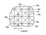
- FIG. 6A relates to the second embodiment
- FIG. 6A is a plan view schematically showing an entering space formed on the surface of the metal member
- FIG. 6B is a cross section schematically showing the entering space formed on the surface of the metal member
- FIG. 6 is a cross-sectional view taken along the line VI-VI.
- Embodiment 4 is a top view which shows typically the protrusion currently formed in the surface of a metal member.
- Embodiment 5 is a top view which shows typically the protrusion currently formed in the surface of a metal member.
- FIG. 17A and FIG. 17B relate to the eleventh embodiment, and are plan views schematically showing projections formed on the surface of a metal member.
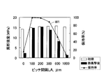
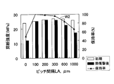
- a horizontal axis is made into a pitch interval of a projection
- a vertical axis is a graph which shows a relation made into shear strength and a retention (%).
- the division of strain based on shear stress generated at the interface will be described by taking a three-layer laminate (initial dimension: li) shown in FIG. 18 of the present invention as an example.
- the actual length of the three-layer stack is l ′.
- the difference between l 'and lx remains as distortion in each layer.
- the shear stress generated by strain exceeds the shear strength of the material, it is believed that cracking occurs and grows.
- the balance of force is basically expressed by Equation 2, and the average dimension l 'of the three-layer laminate can be determined.
- WBL is cracked when the shear stress ⁇ 2 determined by Equation 3 exceeds the shear strength of the second layer WBL.
- the stress due to the difference in linear expansion between the first layer and the third layer is considered, but strain is also generated by the linear expansion of the WBL itself, and shear stress is generated. Therefore, depending on the bonding state of the interface, WBL may generate fine cracks. For this reason, it is considered that the thermal shock based on the repetition of the thermal cycle causes the crack to grow, which leads to the destruction of the WBL.
- the plurality of protrusions such as a wall and a pile are periodically or irregularly formed on the surface of the metal member at a predetermined pitch interval or less.
- the present invention has been developed based on the idea that the strain is divided by the plurality of projections in this manner.
- the pitch interval of the opposing protrusions can be obtained based on Equation 3.
- a composite molded article in which an FRP portion made of PPS resin reinforced with glass fiber is coated on a metal member of aluminum alloy will be added.
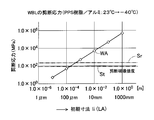
- the relationship between the initial dimension li (corresponding to the pitch interval LA between the facing protrusions) and the shear stress ⁇ 2 was determined.
- the result is shown as a characteristic line WA in FIG.
- the thermal cycle of 23 ° C. ⁇ ⁇ 40 ° C. is one cycle
- the thickness of the FRP portion is 3 mm
- the thickness of the metal member is 3 mm
- the thickness of WBL is 10 nm. Physical property values used for calculation are shown in Table 1.
- the shear strength of the PPS resin itself is shown as a characteristic line St.
- a region above the characteristic line St indicates a region in which WBL itself present at the interface may be destroyed, and a region below the characteristic line St indicates a region in which the WBL itself present at the interface is not destroyed.
- the WBL present at the interface may be destroyed if the initial dimension li between the opposing projections (corresponding to the pitch interval LA between the opposing projections) greatly exceeds 500 micrometers or 1000 micrometers. Becomes higher.
- 100 .mu.m and 1000 .mu.m are only one indication, and the pitch interval LA between the facing projections is appropriately adjusted depending on factors such as the material, rigidity and thickness of the WBL, and the intervals between the projections It is considered that setting the pitch interval LA of less than 3000 micro mail can be one standard. If the rigidity of the polymer material changes in this manner, the pitch interval LA is naturally changed.
- the said protrusion is connected in planar view projected from the orthogonal
- the entry space and the projection are preferably formed by a transfer surface formed on the surface of the metal member.
- a transfer surface a rolling surface (transfer surface) in which the unevenness of the mold surface of a rolling element such as a rotating rolling roller and a non-rotating rolling type (transfer processing element) is transferred to the surface of a metal member is cited.
- Be Roll rollers include knurls.
- the transfer surface the mold (transfer processing element) can be clamped, and the unevenness formed on the molding surface of the mold can be transferred by pressing the surface of the metal member.
- the entry space and the projection may be formed of a blasted surface that causes a group of projectiles to strike the surface of the metal member.
- the projectiles constituting the group of projectiles include shots, grids, sand particles and the like.
- the material of the projectile includes metal and ceramics.
- the grid means particles having a more irregular shape than spherical or pseudo-spherical shots, and generally has high grindability.
- a substantially cylindrical or pseudo-cylindrical cut wire shot obtained by cutting a metal wire in the longitudinal direction can also be used. The cut wire shot has high grindability to the surface of the metal member.
- the metal constituting the metal member is preferably at least one of aluminum, an aluminum alloy, magnesium, a magnesium alloy, iron, an iron alloy, titanium, a titanium alloy, copper, and a copper alloy.
- the polymer material constituting the fiber reinforced polymer material portion may be resin or rubber.
- the resin may be either a thermoplastic resin or a thermosetting resin.
- the polymer material includes nylon (polyamide), polyimide, polyacetal, polyethylene terephthalate (PET), polybutylene terephthalate (PBT), polyphenylene sulfide (PPS), polyether sulfone (PES), polyetherimide ( PEI), polyphenylene ether (PPE), polysulfone, polyethylene, polystyrene, polypropylene, acrylic resin, vinyl chloride resin, fluorine resin, polycarbonate, phenol resin, epoxy resin, unsaturated polyester resin, acrylonitrile-butadiene-styrene (ABS) And at least one of acrylonitrile-butadiene (AB) and a liquid crystal polymer. At least one of these may be the main component.
- the surface of the metal member has a plurality of juxtaposed projections.
- the opposing projections (the closest and the opposite projections) are periodically or irregularly formed at a pitch interval LA larger than the diameter D of the reinforcing fiber so as to form an entry space.
- the adjacent protrusions are preferably connected to each other.
- the protrusions are strengthened, and damage to the protrusions is suppressed. Since a part of the polymeric material which comprises a fiber reinforced polymeric material part approachs an approach space, it is advantageous to further raise the joint strength in an interface. At least a part of the reinforcing fibers can enter into the entry space.
- the pitch distance LA between the protrusions is made larger than the diameter D of the reinforcing fiber.
- the wall surface forming the protrusion has a plurality of micro recesses and / or micro protrusions which are exposed to the entry space.
- the minute recess has a minute opening smaller than the opening size of the entrance space.
- the microconvex portion has a microopening having a protrusion amount smaller than the opening size of the entrance space.
- the minute depressions and minute projections can be formed, for example, by etching, rolling, molding, or may be irradiated with a high energy density beam such as a laser beam.
- the reinforcing fibers constituting the fiber-reinforced polymer material portion are preferably at least one of glass fibers, ceramic fibers, metal fibers, carbon fibers, and high molecular weight high-strength fibers.
- the ceramic fibers include at least one of alumina fibers, silica fibers, alumina-silica fibers, silicon nitride fibers, carbon silicon fibers, and zirconia fibers.
- the high molecular weight high molecular weight fibers include ultra high strength polyethylene fibers, ultra high strength polyvinyl alcohol fibers, aramid fibers and polyacetal fibers.
- the reinforcing fibers include short fibers (fiber length: for example, 1 or 2 millimeters or less), long fibers, whiskers.
- the surface of the metal member has a plurality of protrusions arranged periodically or irregularly.
- LA is larger than the diameter D of the reinforcing fiber (LA> D), where LA is the pitch interval between the facing protrusions.
- the pitch distance LA is set according to factors such as the type (rigidity) of the polymer material (rigidity), the thickness of the WBL, and the diameter D of the reinforcing fiber, but it is an arbitrary value in the range of 10 to 5000 micrometers, 20 to 4000 micrometers And an arbitrary value in the range of 30 to 2000 micrometers, and an arbitrary value in the range of 40 to 1000 micrometers.
- the upper limit value of the pitch distance LA 5000 micrometers, 4000 micrometers, 3000 micrometers, 1500 micrometers, 800 micrometers, 500 micrometers depending on factors such as the type of the polymer material and the diameter D of the reinforcing fiber Furthermore, 400 micrometers, 300 micrometers, 200 micrometers, 150 micrometers, and 130 micrometers are mentioned.
- the lower limit of the pitch distance LA is 10 micrometers, 30 micrometers, 50 micrometers, 70 micrometers according to factors such as the type of polymer material (stiffness), the thickness of WBL and the diameter D of reinforcing fibers It can be mentioned.
- the root pitch distance LB is set according to factors such as the type of polymer material (stiffness), the thickness of WBL and the diameter D of reinforcing fibers, but it is an arbitrary value in the range of 10 to 5000 micrometers, 20 to 4000 For example, arbitrary values in the range of micrometers, arbitrary values in the range of 30 to 2000 micrometers, and arbitrary values in the range of 40 to 1000 micrometers can be exemplified.
- the upper limit value of the pitch distance LA 4000 micrometers, 3000 micrometers, 1500 micrometers, 800 micrometers, 500 micrometers can be mentioned according to factors such as the type of the polymer material and the diameter D of the reinforcing fiber, Furthermore, 400 micrometers, 300 micrometers, 200 micrometers, 150 micrometers, and 130 micrometers are mentioned.
- the lower limit of the pitch distance LA is 10 micrometers, 30 micrometers, 50 micrometers, 70 micrometers according to factors such as the type of polymer material (stiffness), the thickness of WBL and the diameter D of reinforcing fibers It can be mentioned.
- the aperture size LC is set according to factors such as the type (rigidity) of the polymer material (rigidity), the thickness of the WBL, and the diameter D of the reinforcing fiber, but an arbitrary value in the range of 10 to 5000 micrometers, 20 to 4000 micrometers And an arbitrary value in the range of 30 to 2000 micrometers, and an arbitrary value in the range of 40 to 1000 micrometers.
- the upper limit value of the pitch distance LA 5000 micrometers, 4000 micrometers, 3000 micrometers, 1500 micrometers, 800 micrometers, 500 micrometers depending on factors such as the type of the polymer material and the diameter D of the reinforcing fiber Furthermore, 400 micrometers, 300 micrometers, 200 micrometers, 150 micrometers, and 130 micrometers are mentioned.
- the lower limit of the pitch distance LA is 10 micrometers, 30 micrometers, 50 micrometers, 70 micrometers according to factors such as the type of polymer material (stiffness), the thickness of WBL and the diameter D of reinforcing fibers It can be mentioned.
- the pitch interval LA can be tw ⁇ (5 to 100). Further, tw ⁇ (10 to 50) and tw ⁇ (20 to 40) can be adopted. Assuming that the height of the projection is HA (corresponding to the depth of the approach space), the height HA can be LA ⁇ (0.5 to 2). Further, LA ⁇ (0.7 to 1.7) and LA ⁇ (1.0 to 1.5) can be adopted.
- the micro opening of the micro concave portion can be 10 micro mail or less, 7 micro mail or less, 5 micro mail or less, 3 micro mail or less.
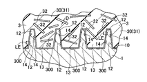
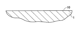
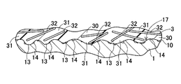
- FIG. 1 shows a cross section of the metal member 1 before covering the FRP portion 3.
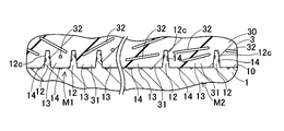
- FIG. 2 shows a cross section of the metal member 1 coated with the FRP portion 3.
- the composite molded product includes a metal member 1 having a surface 10 having an aluminum alloy or a magnesium alloy as a base material, and an FRP portion 3 coated on the surface 10 of the metal member 1 (fiber reinforced polymer material Part) is formed.
- the FRP unit 3 has a resin material 31 (polymer material) to be a matrix 30, and a plurality of reinforcing fibers 32 (for example, glass fibers) for reinforcing the matrix 30.
- the surface 10 of the metal member 1 has a plurality of projections 12 periodically arranged in parallel at a pitch interval LA (see FIG. 1) larger than the diameter D of the reinforcing fibers 32.
- the pitch interval LA is, for example, in the range of 40 to 500 micrometers, in the range of 50 to 300 micrometers, and in the range of 70 to 150 micrometers depending on the type of the matrix 30 constituting the FRP portion 3 There is.
- the height HA of the projection 12 is, for example, in the range of 50 to 200 micrometers, and in the range of 70 to 150 micrometers.
- the wall surfaces 12 c forming the projections 12 face each other, and are opposed to the wall surfaces 12 c adjacent to each other and forming the other projections 12 facing each other.
- the wall surface 12c is inclined at an inclination angle ⁇ with respect to the bottom surface 12e so as to approach the top of the protrusion 12 formed by the wall surface 12c.
- the pitch interval LB (see FIG. 1) at the root of the projection 12 can be smaller than the pitch interval LA at the top of the projection 12. In this case, it is advantageous for enhancing the splitting property of the strain at the interface.
- On the wall surface 12 c forming the protrusion 12 a plurality of minute recesses 14 facing the entry space 13 are formed at random.
- the minute recess 14 has a minute opening smaller than the opening dimension LC of the entrance space 13.
- the minute recesses 14 can be formed by an etching process (wet etching process) after rolling. It is preferable to wash the metal member 1 after the etching process.
- etching process wet etching process
- the metal member 1 is an aluminum alloy or the like, a micro surface oxide thin film is often formed on the surface 10 of the metal member 1. In the case where destruction of the surface oxide thin film of the metal member 1 can be expected by pressing by rolling, the etching process can be promoted.
- the etching solution can contain, for example, OF-901 (made by Sugawara Eugelite), magnesium hydroxide.
- the etching solution can contain water as a solvent and contain 10 g / liter or more of sulfuric acid and 10 g / liter or more of ammonium fluoride.
- the components and composition of the etching solution are not limited to these.
- the FRP portion 3 can be formed by injection molding in a state where the metal member 1 is set in the cavity of the forming die.
- the injection conditions can be, for example, a mold temperature of 40 to 150 ° C., a cylinder temperature of 250 to 350 ° C., an injection pressure of 100 to 180 MPa, and an injection speed of 10 to 100 mm / sec. However, it is not limited to these.
- a pressure holding step was performed to maintain the pressure applied to the resin material loaded in the cavity. This is advantageous for allowing the resin material to favorably enter the entry space 13 between the projections 12 and the minute recesses 14.
- the pressure holding pressure was 40 to 80 MPa, and the pressure holding time was 10 to 15 seconds. It is preferable to heat treat the FRP portion 3 after injection molding. In this case, it can be expected to increase the crystallinity of the resin.
- an entrance space 13 is formed by the protrusions 12 facing each other.
- a part of the resin material 31 constituting the matrix 30 of the FRP portion 3 enters the entry space 13 of the metal member 1, and at least a part of the reinforcing fibers 32 enters. .
- the entry space 13 and the projection 12 before the etching process are formed by a rolling surface 15 which functions as a transfer surface formed on the surface 10 of the metal member 1.
- the plurality of projections 12 can be optionally formed on the surface 10 of the metal member 1 so that the pitch interval LA of the projections 12 and the height HA of the projections 12 are as targeted at the target position. Therefore, the pitch interval LA is uniform over all the protrusions 12.
- the wall surface 12c of the projection 12 has a slope ⁇ (see FIG. 1) with respect to the bottom surface 12e.
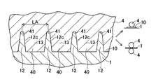
- a metal member 1 having a flat surface 10 shown in FIG. 3 is used.
- the rolling roller 4 transfer processing element
- the rolling convex portion 40 and the rolling groove portion 41 are The surface 10 of the metal member 1 is transferred.
- the entry space 13 and the projection 12 are formed.
- a single rolling roller 4 may be pressed against the metal member 1, or a pair of two rolling rollers 4 (transfer processing element) may be used so as to sandwich the metal member 1.
- Roll forming may be cold working performed in a normal temperature range or may be hot working performed in a hot state, or warm performed in a warm state between hot and cold. It may be processed. When rolling is performed as cold working, strengthening and consolidation of the protrusions 12 by work hardening can be expected. If it is warm processing or hot processing, since the ease of forming can be expected, the material of the metal member 1 may be hard.
- the strain based on the shear stress generated at the interface between the surface 10 of the metal member 1 and the FRP portion 3 can be divided by the plurality of protrusions 12. Therefore, the durability against shear failure at the interface between the surface 10 of the metal member 1 and the FRP portion 3 can be enhanced. Therefore, even when the thermal shock resulting from heating and cooling repeatedly acts on the composite molded article over a long period of time, the peeling of the interface is suppressed, and thus the peeling of the FRP portion 3 is suppressed. Furthermore, according to the present embodiment, as shown in FIG. 2, a part of the resin material 31 and the reinforcing fibers 32 constituting the matrix 30 of the FRP portion 3 enter the entry space 13.
- a plurality of minute recesses 14 are formed in the wall surface 12 c forming the protrusion 12.
- the minute recess 14 has a minute opening facing the entering space 13 between the protrusions 12 and having an opening dimension LE (see FIG. 2) smaller than the opening dimension LC of the entering space 13.
- the probability that the reinforcing fibers 32 included in the FRP portion 3 are present at the interface is low. It is considered that the probability that the thin layer 300 formed only of the resin constituting the part 3 is present at the interface is high.
- the thin layer 300 is formed only of resin and has a low probability of existence of the reinforcing fibers 32, the thin layer 300 is a layer inferior in mechanical strength as compared to the FRP portion 3 itself, and a force such as thermal shock acts In some cases, stress concentration may cause breakage.
- the shear strength at the above-described interface can be further enhanced.
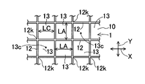
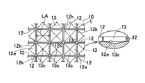
- FIG. 5 shows an example of a plan view of the surface 10 of the metal member 1.
- the protrusions 12 are formed in a lattice wall shape that is connected in the vertical and horizontal directions in the X direction and the Y direction orthogonal to each other. For this reason, it is advantageous to improve the resistance to peeling in a plurality of directions.
- the plan view of the entry space 13 is quadrangular (square, polygonal). Since the projection 12 is continuously formed so as to make one turn around the central portion 13c of the entrance space 13 in plan view, it is advantageous for reducing the anisotropy of the entrance space 13 with respect to the central portion 13c. . Therefore, it is advantageous to reduce the anisotropy to exfoliation. As shown in FIG.
- the protrusions 12 since the protrusions 12 are cross-connected, they have a plurality of crossing portions 12k.
- the protrusion 12 is reinforced by the intersection 12k. Therefore, even when the shear stress is large, or even when the thickness of the protrusion 12 is thin, the overturn and deformation of the protrusion 12 are suppressed as much as possible. Therefore, the effect of dividing the strain can be maintained for a long time. In particular, when rolling is carried out cold, reinforcement of the projections 12 and the intersection 12k by work hardening can be expected. However, the crossing portion 12k may be eliminated and the respective protrusions 12 may be made independent.
- the etching process may be eliminated and the minute recesses 14 may not be formed in the protrusions 12. Even in this case, since the strain based on the shear stress at the interface can be divided by the protrusions 12, the peeling resistance of the FRP portion 3 can be enhanced.
- FIG. 6 shows a second embodiment. This embodiment basically has the same configuration and the same effects as the first embodiment. The following description will focus on the differences.
- FIG. 6A shows a plan view of a plurality of entry spaces 13 arranged in parallel.
- FIG. 6B shows a cross section taken along line VI-VI of FIG. 6A.
- a plurality of entry spaces 13 formed by the protrusions 12 are formed vertically and horizontally.
- the entrance space 13 has a square pyramid shape. Therefore, the convex part which comprises the approach space 13 among rolling rollers (transfer element) has comprised the regular quadrangular pyramid shape provided with the top equivalent to the center part 13c. The high biting property to the metal member 1 is secured.
- the wall surface 12c which comprises the approach space 13 has comprised triangle shape.
- the central portion 13c at the bottom is the deepest bottom in the entry space 13, and corresponds to the position of the top of the square pyramidal convex portion of the above-described rolling roller.
- the thickness of the top 12p of the projection 12 is substantially zero.
- the thickness of the protrusion 12 increases toward the central portion 13 c, and the strength of the entire protrusion 12 is secured.
- FIG. 7 shows a third embodiment.
- This embodiment basically has the same configuration and the same effects as the first embodiment. The following description will focus on the differences.
- the metal member 1 is installed on the mounting surface 50 a of the holding mold 50.
- the mold 52 transfer processing element
- the transfer mold 52 c is moved downward in one direction (Z direction) to press the surface 10 of the metal member 1.
- the mold 52 is lifted to be separated from the holding mold 50.
- the protrusion 12 and the entry space 13 are formed on the surface 10 of the metal member 1.
- the pressing direction of the forming die 52 is one direction
- the separating direction of the forming die 52 is the direction opposite to the pressing direction, so the transfer accuracy of the projection 12 is high.
- the forming process may be cold working, hot working or warm working. Also in the present embodiment, it is preferable to form the minute concaves by the etching process, but the etching process may be omitted in some cases if the peeling resistance is sufficiently ensured. Even in this case, since the strain based on the shear stress at the interface can be divided by the protrusions 12, the peeling resistance of the FRP portion 3 can be enhanced.
- FIG. 8 shows a fourth embodiment. This embodiment basically has the same configuration and the same effects as the first to third embodiments. The following description will focus on the differences.
- FIG. 8 shows a plan view of the projection 12 and the entry space 13 formed on the surface 10 of the metal member 1.
- the opposing protrusion 12 is reinforced by the intersection 12k, and can maintain the effect of dividing the strain for a long time.
- the entrance space 13 has a rectangular shape (square) in plan view. And the depth of central part 13c of bottom 12e of entrance space 13 is made the deepest. The depth is shallow from the central portion 13 c toward the projection 12.
- the reinforcing fibers 32 can easily enter the central portion 13 c of the entry space 13. In this case, it is advantageous to reinforce the resin material that has entered the entry space 13. Therefore, it is advantageous for suppressing separation of the interface between the FRP portion 3 and the surface 10 of the metal member 1. Also in the present embodiment, it is preferable to form a plurality of minute recesses in the protrusion 12 at random by performing an etching process. However, depending on the case, it is not necessary to abolish the etching process and not to form a minute concave portion. Even in this case, since the strain based on the shear stress at the interface can be divided by the protrusions 12, the peeling resistance of the FRP portion 3 can be enhanced.
- FIG. 9 shows a fifth embodiment.
- the present embodiment basically has the same configuration and the same effects as the first and second embodiments. The following description will focus on the differences.
- FIG. 9 shows a plan view of the projection 12 and the entry space 13 formed on the surface 10 of the metal member 1.
- the entrance space 13 is a plane and has a hexagonal shape (polygon, regular polygon).
- the projections 12 are formed continuously so as to make one round around the central portion 13c of the bottom surface 12e of the entry space 13, which is advantageous for reducing anisotropy with respect to the central portion 13c of the entry space 13. . Therefore, it is advantageous to reduce the anisotropy to exfoliation.
- the depth of the central portion 13c may be the deepest, or the depth of the entrance space 13 may be a uniform depth.
- the pitch interval LA of the protrusions 12 can be the longest distance between the protrusions 12. Also in the present embodiment, it is preferable to perform the etching process to form the minute recess in the protrusion 12. However, depending on the case, it is not necessary to abolish the etching process and not to form a minute concave portion.
- FIG. 10 shows a sixth embodiment.
- the present embodiment basically has the same configuration and the same effects as the first and second embodiments. The following description will focus on the differences.
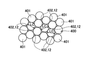
- a transfer processing element 400 is formed by bundling and collecting a plurality of wire rods 401 having a circular cross-sectional shape. There is a gap 402 between the facing wires 401.
- the protrusion 12 is formed at a portion corresponding to the gap 402. The protrusions 12 are not connected to each other, and independently protrude from the surface of the metal member. As shown in FIG.
- the opening dimension LC between the facing projections 12 basically corresponds to the outer diameter dimension of the wire 401.
- the outer diameter of the wire 401 may be reduced. Since the transfer processing element 400 is formed by bundling and collecting the plurality of wires 401, the structure of the transfer processing element 400 is simplified. Even if broken, the wire rod 401 may be replaced. Also in the present embodiment, it is preferable to form the minute recesses in the projection 12 by performing an etching process. However, depending on the case, it is not necessary to abolish the etching process and not to form a minute concave portion.
- Seventh Embodiment 11 and 12 show a seventh embodiment.
- the present embodiment basically has the same configuration and the same effects as the first and second embodiments. The following description will focus on the differences.
- the entry space 13 and the projection 12 are formed as a rolling surface that functions as a transfer surface formed on the surface 10 of the metal member 1 formed of an aluminum alloy.
- the pitch intervals between the opposing protrusions 12 are uneven. Specifically, in the region M2 where the thermal shock is relatively small in the composite molded product, the pitch interval LA2 is set relatively large. However, in the region M1 in which the thermal shock is relatively large, the pitch distance LA1 is relatively small, so that the strain due to the shear stress due to the thermal shock can be separated, and the separation at the interface can be suppressed.
- the wall surface 12 c forming the projection 12 has a plurality of minute recesses 14 exposed to the entry space 13.
- the degree of engagement at the interface between the surface 10 of the metal member 1 and the FRP portion 3 can be further enhanced, and the shear strength at the interface described above can be further enhanced.
- peeling of the FRP portion 3 is further suppressed even when the thermal shock due to heating and cooling acts repeatedly on the composite molded article over a long period of time. Be done.
- the etching process may be eliminated and the minute recesses 14 may not be formed.
- (Embodiment 8) 1 to 5 can be applied correspondingly.
- the entry space 13 and the projection 12 are formed by a rolled surface formed on the surface 10 of the metal member 1 formed of an aluminum alloy.
- the strain based on the shear stress caused by the thermal shock can be divided, and the separation at the interface can be suppressed.
- the height of the protrusions 12 is HA
- the pitch interval is LA
- the average fiber length of the reinforcing fibers 32 (for example, glass fibers) embedded in the matrix 30 is K
- the diameter of the reinforcing fibers 32 is D
- LA Is made larger than (1.2-5) ⁇ HA. Furthermore, it is larger than (2.0 to 4.0) ⁇ HA.
- LA is made larger than K and D.
- the reinforcing fiber 32 in addition to the resin of the matrix 30 entering into the entry space 13 formed in the facing protrusion 12, the reinforcing fiber 32 easily enters. In this case, it can be expected that the shear strength of the interface can be as high as possible with glass fibers. According to such this embodiment, even when the thermal shock due to heating and cooling acts repeatedly on the composite molded article over a long period of time, peeling of the FRP portion 3 is further suppressed. Also in the present embodiment, it is preferable to form the minute recess in the projection 12 by performing an etching process or the like. However, depending on the case, it is not necessary to abolish the etching process and not to form a minute concave portion.
- the entry space 13 and the projection 12 are formed of a blast treated surface 17 in which a group of projectiles such as shots, grids, sand particles and the like is made to collide with the surface 10 of the metal member 1 formed of aluminum alloy. It is considered that a portion having a relatively low hardness in the surface 10 of the metal member 1 is scraped to form the entry space 13. Of the surface 10 of the metal member 1, it is considered that the portion with relatively high hardness or the portion with less collisions of the projectile forms the protrusion 12.
- the pitch interval LA between the opposing protrusions 12 is uneven, as in the embodiments described above, the strain based on shear stress caused by thermal shock can be divided by the protrusions 12 and peeling at the interface It can be suppressed.
- a part of resin material 31 which comprises the matrix 30 of the FRP part 3 approachs into the approach space 13
- a part of reinforcement fiber 32 (glass fiber) approachs.
- the shear strength at the interface between the surface 10 of the metal member 1 and the FRP portion 3 can be increased.
- at least a part of the reinforcing fibers 32 can enter into the entry space 13 present between the facing projections 12.
- the resin material 31 entering the entry space 13 can be reinforced, and the shear strength at the interface can be further enhanced.
- the wall surface 12 c forming the protrusion 12 has a plurality of minute recesses 14 exposed to the entry space 13.
- the degree of engagement at the interface between the metal member 1 and the FRP portion 3 can be further enhanced, and the shear strength at the interface described above can be further enhanced.
- the peeling of the FRP portion 3 is further suppressed even when the thermal shock due to heating and cooling acts repeatedly over a long period of time.
- the removal of the surface oxide thin film of the metal member 1 can be expected by the cleaning action or grinding action based on the blast treatment. In this case, since the exposure of the metal base material is increased, the etching process can be promoted. However, depending on the case, it is not necessary to abolish the etching process and not to form a minute concave portion.
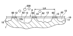
- the entry space 13 and the projection 12 are formed by a blast treated surface 17 in which a group of projectiles 500 collide with the surface 10 of the metal member 1 formed of metal such as aluminum alloy.
- a masking member 6 having a covering portion 60 and a space 62 is used.
- a group of projectiles 500 size capable of passing through the space 62 collides with the surface 10 of the metal member 1 from above.
- the portion facing the space 62 is scraped to form an entry space 13 in order to allow collision of the projectile 500 such as a shot, grid, sand or the like.
- the portion covered by the covering portion 60 can limit the collision of the projectile 500, and thus forms the protrusion 12.
- the masking member 6 is preferably made of a hard material (for example, carbon steel, alloy steel, ceramics). In this case, since the pitch distance LA between the protrusions 12 substantially corresponds to the pitch distance of the covering portions 60 of the masking member 6, it is set as a target.
- the pitch interval LA between the protrusions 12 can be adjusted.
- the pitch distance LA between the protrusions 12 can be set as desired.
- the advantage of being able to The masking member 6 may be formed by covering the metal member 1 with a soft material such as a resist film that is worn by blasting. Also in this case, since the wear can be suppressed by the masking member 6 in the initial and middle stages of the blast, the projection can be formed.
- the strain caused by thermal shock can be divided by the protrusions 12, and peeling at the interface between the surface 10 of the metal member 1 and the FRP portion 3 can be suppressed.
- a part of the resin material 31 constituting the matrix 30 of the FRP section 3 enters the entrance space 13 and a part of the reinforcing fiber 32 enters.
- the shear strength at the interface between the surface 10 of the metal member 1 and the FRP portion 3 can be further enhanced.
- the wall surface 12 c forming the protrusion 12 has a plurality of minute recesses 14 exposed to the entry space 13.
- the degree of engagement at the interface between the surface 10 of the metal member 1 and the FRP portion 3 can be further enhanced, and the shear strength at the interface described above can be further enhanced.
- peeling of the FRP portion 3 is further suppressed Ru.
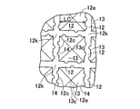
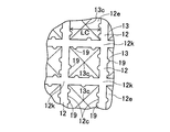
- FIG. 17 shows a plan view of the entry space 13 and the projection 12 before the FRP portion is covered.
- the entry space 13 and the projection 12 are formed by the application of pressure from the form-rolling roll functioning as a transfer processing element or the application of pressure to the molding surface of the mold.
- the protrusions 12 are formed in a grid shape.
- a plurality of minute recesses 14 are formed in the wall surface 12 c of the protrusion 12 so as to be exposed to the entry space 13.
- the minute recess 14 has a minute opening smaller than the opening dimension LC of the entrance space 13.
- a plurality of minute convex portions 19 are formed on the wall surface 12 c of the protrusion 12 so as to face the entry space 13.
- the micro-convex portion 19 has a protrusion amount smaller than the opening size LC of the entry space 13. Furthermore, the amount of protrusion of the micro-convex portion 19 has a smaller amount of protrusion than the wall thickness of the root portion of the protrusion 12 forming the entry space 13.
- the minute recesses 14 and the minute projections 19 can be formed simultaneously with the formation of the projections 12 and the entry space 13 by the pressure of the rolling rolls or the pressure of the forming surface of the forming die, so the process can be simplified. We can expect the abolition and contribute to cost reduction. In addition, when forming the minute recesses 14 and the minute projections 19, if the cold working is performed, it is also possible to expect the reinforcement of the protrusions 12 by work hardening. Here, since the thickness of the protrusion 12 is reduced when the minute recess 14 is formed in the protrusion 12, concern about the strength of the protrusion 12 may occur, but the protrusions 12 are connected to each other. The protrusion 12 can be connected and strengthened by the intersecting portion 12k. Therefore, the durability against peeling can be improved over a long period of time. In some cases, the protrusions 12 may be independent without providing the intersection 12k.
- a part of the matrix 30 constituting the FRP portion 3 can enter the entry space 13 and engage with the minute recesses 14 and the minute projections 19 facing the approach space 13.
- the engagement between the FRP portion 3 and the protrusion 12 of the metal member 1 can be further improved, which is advantageous for suppressing the peeling of the FRP portion 3.
- the minute projections 19 project toward the opposing projections 12 and thus can contribute to reducing the pitch interval LA of the opposing projections 12 and can improve the division of distortion.
- the minute recesses 14 and the minute projections 19 may be mixed on the wall surface 12 c of the protrusion 12.
- the etching process can be eliminated, but in some cases, the etching process may be used in combination.
- Example 1 Rolled roller (material: cemented carbide) on the surface 10 of a metal piece (corresponding to the metal member 1) consisting of a flat plate (aluminium extruded material, JIS A5052) having a size of 25 mm wide, 100 mm long and 3 mm thick )
- a metal piece was fixed on a milling machine and executed using a rolling roller as a blade.
- the stage speed was 75 mm / min
- the outside diameter of the rolling roller was 20 mm
- the depth of cut was 70 micrometers.
- An entrance space 13 is formed by the opposing projections 12.
- the pitch distance LA at the center of the apex of the adjacent protrusion 12 was 100 micrometers
- the depth HA was 67 micrometers
- the inclination angle ⁇ was 60 degrees.
- the etching solution contains water as the solvent, 12 g / L of OF-901 (manufactured by Kugahara Eugelite), and 25 g / L of magnesium hydroxide.
- the target temperature of the etching solution was 50 ° C., and the etching time was 10 minutes. Thereafter, the metal piece was set in the cavity of a mold for injection molding.
- the dimension of the overlapping portion of the metal member and the FRP portion was 25 mm ⁇ 10 mm.
- injection molding conditions were a mold temperature of 130 ° C., a cylinder temperature of 320 ° C., an injection pressure of 100 MPa, an injection speed of 60 mm / sec, an injection time of 1 second, and a screw rotation speed of 100 rpm.
- a pressure holding step was performed to maintain the pressure applied to the resin material loaded in the cavity. This is advantageous for allowing the resin material to favorably enter the entry space 13 between the projections 12 and the minute recesses 14.
- the pressure holding pressure was 50 MPa, and the pressure holding time was 10 seconds.
- the FRP portion 3 (glass fiber: 30% by mass, PPS: 70% by mass) corresponds to a fiber reinforced polymer material portion.
- the metal piece corresponds to the metal member 1.
- the glass fiber compounded into the resin material before injection molding used had an average diameter of 13 micrometers and an average fiber length of 3 millimeters (Nittobo Co., Ltd.). However, glass fibers may be broken and shortened by injection molding. When measured after molding, the average fiber length of the glass fiber was 100 micrometers.
- Example 2 The present embodiment basically has the same configuration as that of the first embodiment, and the same function and effect.
- a plurality of projections 12 were formed by rolling on the surface 10 of a metal piece (corresponding to the metal member 1) made of a flat plate (aluminum extrusion material) of the same type as that of the first embodiment.
- the pitch distance LA of the apexes of the adjacent protrusions 12 was 200 micrometers
- the depth HA was 67 micrometers
- the inclination angle ⁇ was 38 degrees.
- an etching process was performed to form pores (corresponding to the minute recesses 14) on the surface 10 of the protrusion 12.
- the fine openings of the pores face the entry space 13.
- the aperture of the minute aperture was about 3 micrometers, and the depth was about 10 micrometers.
- the metal piece was set in the cavity of a mold for injection molding.
- a resin material glass fiber: 30% by mass
- FRP portion 3 thickness: 3 mm
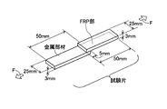
- metal piece A test piece (see FIG. 20) formed of the integrated composite molded article was formed.
- the conditions for injection molding were the same as in Example 1.
- the present embodiment basically has the same configuration as that of the first embodiment, and the same function and effect.
- a plurality of projections 12 were formed by rolling on the surface 10 of a metal piece (corresponding to the metal member 1) made of a flat plate (aluminum extrusion material) of the same type as that of the first embodiment.
- the pitch distance LA of the apexes of the adjacent protrusions 12 was 200 micrometers
- the depth HA was 133 micrometers
- the inclination angle ⁇ was 60 degrees.
- an etching process was performed to form pores (corresponding to the minute recesses 14) on the surface 10 of the protrusion 12.
- the aperture of the minute aperture was about 3 micrometers, and the depth was about 10 micrometers.
- Example 1 a resin material (glass fiber: 30% by mass) formed of PPS resin containing glass fiber is injection molded into a cavity, and FRP portion 3 (thickness: 3 mm) and metal piece A test piece (see FIG. 20) formed of the integrated composite molded article was formed.
- the conditions for injection molding were the same as in Example 1.
- Example 4 basically has the same configuration as that of the first embodiment, and the same function and effect.
- a rough surface was formed on the surface 10 of a metal piece (corresponding to the metal member 1) made of a flat plate (aluminum extruded material) of the same type as in Example 1 by blasting.
- the conditions for the blast treatment were a shot diameter of 0.3 to 0.5 mm (indeterminate form), a shot hardness of 40 to 50 HRC, and a projection speed of 80 m / sec.
- the rough surface after blasting had an average roughness of 100 to 120 z (Rz).
- a plurality of projections 12 are irregularly and juxtaposedly arranged in an irregular manner.
- the pitch distance LA between the apexes of the adjacent protrusions 12 was 100 micrometers or more, and the depth HA was about 50 to 150 micrometers.
- an etching process was performed to form pores (corresponding to the minute recesses 14) on the surface 10 of the protrusion 12.
- the aperture of the minute aperture was about 3 micrometers, and the depth was about 10 micrometers.
- the metal piece was set in the cavity of a mold for injection molding.
- a resin material (glass fiber: 30% by mass) formed of PPS resin containing glass fiber is injection molded into a cavity, and FRP portion 3 (thickness: 3 mm) and metal piece A test piece (see FIG. 20) formed of the integrated composite molded article was formed.
- the conditions for injection molding were the same as in Example 1.
- the present embodiment basically has the same configuration as that of the first embodiment, and the same function and effect.
- a plurality of projections 12 were formed by rolling on the surface 10 of a metal piece (corresponding to the metal member 1) made of a flat plate (aluminum extrusion material) of the same type as that of the first embodiment.
- the pitch interval LA at the top of the adjacent protrusion 12 was 100 micrometers
- the depth HA was 67 micrometers
- the inclination angle ⁇ was 60 degrees.
- an etching process was performed to form pores (corresponding to the minute recesses 14) on the surface 10 of the protrusion 12.
- the aperture of the minute aperture was about 3 micrometers, and the depth was about 10 micrometers.
- the piece of metal was then heated to 300 ° C. on a hot plate. Then, the resin sheet (glass fiber: 30 mass%) formed with PPS resin containing glass fiber was crimped
- the present embodiment basically has the same configuration as that of the first embodiment, and the same function and effect.
- a plurality of projections 12 were formed by rolling on the surface 10 of a metal piece (corresponding to the metal member 1) made of a flat plate (aluminum extrusion material) of the same type as that of the first embodiment.
- the pitch distance LA of the apexes of the adjacent protrusions 12 was 200 micrometers
- the depth HA was 67 micrometers
- the inclination angle ⁇ was 38 degrees.
- an etching process was performed to form pores (corresponding to the minute recesses 14) on the surface 10 of the protrusion 12.
- the aperture of the minute aperture was about 3 micrometers, and the depth was about 10 micrometers.
- the piece of metal was then heated to 300 ° C. on a hot plate. Then, the resin sheet (glass fiber: 30 mass%) formed with PPS resin containing glass fiber was crimped
- the present embodiment basically has the same configuration as that of the first embodiment, and the same function and effect.
- a plurality of projections 12 were formed by rolling on the surface 10 of a metal piece (corresponding to the metal member 1) made of a flat plate (aluminum extrusion material) of the same type as that of the first embodiment.
- the pitch distance LA of the apexes of the adjacent protrusions 12 was 200 micrometers
- the depth HA was 133 micrometers
- the inclination angle ⁇ was 60 degrees.
- an etching process was performed to form pores (corresponding to the minute recesses 14) on the surface 10 of the protrusion 12.
- the aperture of the minute aperture was about 3 micrometers, and the depth was about 10 micrometers.
- the piece of metal was then heated to 300 ° C. on a hot plate. Then, the resin sheet (glass fiber: 30 mass%) formed with PPS resin containing glass fiber was crimped
- Example 8 The present embodiment basically has the same configuration as that of the first embodiment, and the same function and effect.
- a rough surface was formed on the surface 10 of a metal piece (corresponding to the metal member 1) made of a flat plate (aluminum extruded material) of the same type as in Example 1 by blasting.
- the rough surface had an average roughness of 100 to 120 z (Rz).
- a plurality of projections 12 are irregularly juxtaposed on the rough surface.
- the pitch interval LA at the top of the adjacent projection 12 is basically 100 micrometers or more, and the depth HA is basically about 50 to 100 micrometers.
- an etching process was performed to form pores (corresponding to the minute recesses 14) on the surface 10 of the protrusion 12.
- the aperture of the minute aperture was about 3 micrometers, and the depth was about 10 micrometers.
- the piece of metal was then heated to 300 ° C. on a hot plate. Then, the resin sheet (glass fiber: 30 mass%) formed with PPS resin containing glass fiber was crimped
- Comparative Example 1 In Comparative Example 1, no protrusion is formed. Pores were formed on the surface of a metal piece (corresponding to a metal member) made of a flat plate (aluminum extruded material) of the same type as in Example 1 by etching. The openings of the micropores of the pores were about 3 micrometers, and the depth was about 10 micrometers. The surface of the metal piece is neither rolled nor blasted. Thereafter, a metal piece is set in a cavity of a mold for injection molding, and as in Example 1, a resin material (glass fiber: 30% by mass) formed of PPS resin containing glass fiber is injection molded in the cavity A test piece (see FIG. 20) was formed of a composite molded product in which the FRP portion 3 (thickness: 3 mm) and the metal piece were integrated. The conditions for injection molding were the same as in Example 1.
- Comparative Example 2 In Comparative Example 1, no protrusion is formed. Pores were formed on the surface of a metal piece (corresponding to a metal member) made of a flat plate (aluminum extruded material) of the same type as in Example 1 by etching. The openings of the micropores of the pores were about 3 micrometers, and the depth was about 10 micrometers. The surface of the metal piece is neither rolled nor blasted. The metal pieces were then heated to 300 ° C. on a hot plate. Then, the resin sheet (glass fiber: 30 mass%) formed with PPS resin containing glass fiber was crimped
- That the shear strength of the test piece is 30 Mpa means that the FRP portion 3 itself is broken, not the peeling at the interface between the metal member 1 and the FRP portion 3 of the test piece. Therefore, as can be understood from Table 2, in Examples 1 to 8, the initial shear strength at the interface was good, and not the peeling at the interface between the metal member 1 and the FRP portion 3 but the FRP portion 3 itself was broken . When the thermal shock is repeatedly applied, in Examples 1, 3, 5 and 7, the shear strength at the interface is good, not the peeling at the interface between the metal member 1 and the FRP portion 3, but the FRP portion 3 itself was destroyed. In Example 2, the interface was broken, and the shear strength at the interface was 23 MPa, which was good.
- Example 4 The interface was broken for Example 4, and the shear strength at the interface was 29 MPa, which was good. In Example 6, the interface was broken, and the shear strength at the interface was 19 MPa, which was good. The interface was broken for Example 8, and the shear strength at the interface was 27 MPa, which was good. In Comparative Examples 1 to 4, the shear strength after thermal shock was low.
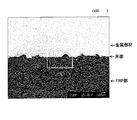
- FIG. 21 shows a photograph of the interface of the test piece (blasted and etched) according to Example 8 taken by a scanning electron microscope.
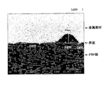
- FIG. 22 is an enlarged view of a region partitioned by white lines in FIG. As shown in FIG. 21 and FIG. 22, the resin material of the FRP portion is loaded and the glass fiber enters into the entry space between the protrusions.
- the pitch distance LA between the opposing protrusions is considered to be about 100 to 300 micrometers on average.
- Example 1B A mold (material: cemented carbide) is applied to the surface 10 of a metal piece (corresponding to the metal member 1) consisting of a flat plate (aluminium extruded material, JIS A5052) with a size of 25 mm wide, 50 mm long and 3 mm thick. It pressed and formed the some protrusion 12 (refer FIG. 1).
- the mold has pyramidal convexities with a pitch between vertices of 100 micrometers and a depth of 67 micrometers. Thereby, it formed in the surface 10 of a metal piece (equivalent to the metal member 1).
- the pitch distance LA at the center of the apex of the adjacent protrusion 12 was 100 micrometers, the depth HA was 50 micrometers, and the inclination angle ⁇ (see FIG. 1) was 60 degrees.
- the entrance space 13 was formed by the opposing protrusion 12.
- an etching process was performed to form pores (corresponding to the minute recesses 14) on the surface 10 of the protrusion 12.
- the fine openings of the pores face the entry space 13.
- the micro openings had an opening of 3 micrometers or less (about 200 nanometers at the minimum) and a depth of 10 micrometers or less (about 200 nanometers at the minimum).
- the etching solution contains water as the solvent, 12 g / L of OF-901 (manufactured by Sugawara Eugelite), and 25 g / L of magnesium hydroxide.
- the target temperature of the etching solution was 50 ° C., and the etching time was 10 minutes.
- injection molding conditions were a mold temperature of 130 ° C., a cylinder temperature of 320 ° C., an injection pressure of 100 MPa, an injection speed of 60 mm / sec, an injection time of 1 second, and a screw rotation speed of 100 rpm.
- a pressure holding step was performed to maintain the pressure applied to the resin material loaded in the cavity. This is advantageous for allowing the resin material to favorably enter the entry space 13 between the projections 12 and the minute recesses 14.
- the pressure holding pressure was 50 MPa, and the pressure holding time was 10 seconds.
- the FRP part 3 glass fiber: 30% by mass
- the metal piece corresponds to the metal member 1.
- the glass fiber compounded into the resin material before injection molding used had an average diameter of 13 micrometers and an average fiber length of 3 millimeters (Nittobo Co., Ltd.). However, glass fibers may be broken and shortened by injection molding. When measured after molding, the average fiber length of the glass fiber was 100 micrometers.
- the test pieces were heat-treated in a high temperature bath at 120 ° C. for 24 hours, and subjected to an evaluation test described later.
- Example 2B is basically the same as Example 1B.
- the mold material: cemented carbide
- the mold material: cemented carbide
- the mold pressed against the surface 10 of the metal piece (corresponding to the metal member 1) has a pyramidal convex portion with a pitch of 200 micrometers between peaks and a depth of 133 micrometers. Thereby, it formed in the surface 10 of a metal piece (equivalent to the metal member 1).
- the pitch distance LA at the center of the apex of the adjacent protrusion 12 was 200 micrometers
- the depth HA was 100 micrometers
- the inclination angle ⁇ was 60 degrees.
- pores corresponding to the minute recesses 14 were formed on the surface 10 of the projection 12 by etching.
- test piece formed of a composite molded product in which a resin material formed of nylon containing glass fiber is injection molded in a cavity and the FRP portion 3 (thickness: 3 mm) and a metal piece are integrated (FIG. 23) Reference).
- the test pieces were heat-treated in a high temperature bath at 120 ° C. for 24 hours, and subjected to an evaluation test described later.
- Example 3B is basically the same as Example 1B.
- the mold material: cemented carbide
- the mold material: cemented carbide
- the mold pressed against the surface 10 of the metal piece (corresponding to the metal member 1) has a pyramidal convex portion with a pitch of 300 micrometers between peaks and a depth of 200 micrometers. Thereby, it formed in the surface 10 of a metal piece (equivalent to the metal member 1).
- the pitch distance LA at the center of the apex of the adjacent protrusion 12 was 300 micrometers
- the depth HA was 160 micrometers
- the inclination angle ⁇ was 60 degrees.
- pores corresponding to the minute recesses 14 were formed on the surface 10 of the projection 12 by etching.
- test piece formed of a composite molded product in which a resin material formed of nylon containing glass fiber is injection molded in a cavity and the FRP portion 3 (thickness: 3 mm) and a metal piece are integrated (FIG. 23) Reference).
- the test pieces were heat-treated in a high temperature bath at 120 ° C. for 24 hours, and subjected to an evaluation test described later.
- Example 4B is basically the same as Example 1B.
- the mold material: cemented carbide
- the mold material: cemented carbide
- the mold pressed against the surface 10 of the metal piece (corresponding to the metal member 1) has a pyramid-shaped convex portion with a pitch of 600 micrometers between peaks and a depth of 400 micrometers. Thereby, it formed in the surface 10 of a metal piece (equivalent to the metal member 1).
- the pitch distance LA at the center of the apex of the adjacent protrusion 12 was 600 micrometers
- the depth HA was 300 micrometers
- the inclination angle ⁇ was 60 degrees.
- pores corresponding to the minute recesses 14 were formed on the surface 10 of the projection 12 by etching.
- test piece formed of a composite molded product in which a resin material formed of nylon containing glass fiber is injection molded in a cavity and the FRP portion 3 (thickness: 3 mm) and a metal piece are integrated (FIG. 23) Reference).
- the test pieces were heat-treated in a high temperature bath at 120 ° C. for 24 hours, and subjected to an evaluation test described later.
- Example 5B is basically the same as Example 1B.
- the mold material: cemented carbide
- the mold material: cemented carbide
- the mold pressed against the surface 10 of the metal piece (corresponding to the metal member 1) has a pyramidal convex portion with a pitch of 1000 micrometers between peaks and a depth of 400 micrometers. Thereby, it formed in the surface 10 of a metal piece (equivalent to the metal member 1).
- the pitch distance LA at the center of the apex of the adjacent protrusion 12 was 1000 micrometers
- the depth HA was 310 micrometers
- the inclination angle ⁇ was 60 degrees.
- pores corresponding to the minute recesses 14 were formed on the surface 10 of the projection 12 by etching.
- test piece formed of a composite molded product in which a resin material formed of nylon containing glass fiber is injection molded in a cavity and the FRP portion 3 (thickness: 3 mm) and a metal piece are integrated (FIG. 23) Reference).
- the test pieces were heat-treated in a high temperature bath at 120 ° C. for 24 hours, and subjected to an evaluation test described later.
- Example 6B is basically the same as Example 1B.
- the mold material: cemented carbide
- the mold material: cemented carbide
- the mold pressed against the surface 10 of the metal piece (corresponding to the metal member 1) has a pyramidal convex portion with a pitch of 200 micrometers between peaks and a depth of 67 micrometers.
- the pitch distance LA at the center of the apex of the adjacent protrusion 12 was 200 micrometers
- the depth HA was 50 micrometers
- the inclination angle ⁇ (see FIG. 1) was 60 degrees.
- pores corresponding to the minute recesses 14 were formed on the surface 10 of the projection 12 by etching.
- test piece formed of a composite molded product in which a resin material formed of a nylon resin containing glass fiber is injection molded in a cavity and the FRP portion 3 (thickness: 3 mm) and a metal piece are integrated (Fig. 23).
- the test pieces were heat-treated in a high temperature bath at 120 ° C. for 24 hours, and subjected to an evaluation test described later.
- Comparative Example 1B Comparative Example 1B is basically the same as Example 1B. However, no protrusion was formed, and the mold (material: cemented carbide) was not pressed against the surface 10 of the metal piece (corresponding to the metal member 1). In Comparative Example 1B, the surface 10 of the metal piece (corresponding to the metal member 1) was etched to form pores (corresponding to the minute recesses 14) on the surface 10 of the protrusion 12. The fine openings of the pores face the entry space 13. The micro openings had an opening of 3 micrometers or less (about 200 nanometers at the minimum) and a depth of 10 micrometers or less (about 200 nanometers at the minimum).
- the etching solution contains water as the solvent, 12 g / L of OF-901 (manufactured by Sugawara Eugelite), and 25 g / L of magnesium hydroxide.
- the target temperature of the etching solution was 50 ° C., and the etching time was 10 minutes.
- the test pieces were heat-treated in a high temperature bath at 120 ° C. for 24 hours, and subjected to an evaluation test described later.
- Example 1C is basically the same as Example 1B. That is, a mold (material: cemented carbide) is formed on the surface 10 of a metal piece (corresponding to the metal member 1) made of a flat plate (aluminium extruded material, JIS A5052) having a size of 25 mm wide, 50 mm long and 3 mm thick. ) Are formed to form a plurality of projections 12 (see FIG. 1).
- the mold has pyramidal convexities with a pitch between vertices of 100 micrometers and a depth of 67 micrometers. Thereby, it formed in the surface 10 of a metal piece (equivalent to the metal member 1).
- the pitch distance LA at the center of the apex of the adjacent protrusion 12 was 100 micrometers, the depth HA was 50 micrometers, and the inclination angle ⁇ (see FIG. 1) was 60 degrees.
- the entrance space 13 was formed by the opposing protrusion 12.
- an etching process was performed to form pores (corresponding to the minute recesses 14) on the surface 10 of the protrusion 12.
- the fine openings of the pores face the entry space 13.
- the micro openings had an opening of 3 micrometers or less (about 200 nanometers at the minimum) and a depth of 10 micrometers or less (about 200 nanometers at the minimum).
- the metal piece was set in the cavity of a mold for injection molding.
- the dimension of the overlapping portion of the metal member and the FRP portion was 5 mm ⁇ 25 mm.
- injection molding conditions were a mold temperature of 130 ° C., a cylinder temperature of 320 ° C., an injection pressure of 100 MPa, an injection speed of 60 mm / sec, an injection time of 1 second, and a screw rotation speed of 100 rpm.
- a pressure holding step was performed to maintain the pressure applied to the resin material loaded in the cavity.
- the pressure holding pressure was 50 MPa, and the pressure holding time was 10 seconds.
- the FRP part 3 glass fiber: 30% by mass
- the metal piece corresponds to the metal member 1. After injection molding, the test pieces were heat-treated in a high temperature bath at 120 ° C. for 24 hours, and subjected to an evaluation test described later.
- Example 2C is basically the same as Example 1B.
- the mold material: cemented carbide
- the mold material: cemented carbide
- the mold pressed against the surface 10 of the metal piece (corresponding to the metal member 1) has a pyramidal convex portion with a pitch of 200 micrometers between peaks and a depth of 133 micrometers.
- the pitch distance LA at the center of the apex of the adjacent protrusion 12 was 200 micrometers
- the depth HA was 100 micrometers
- the inclination angle ⁇ (see FIG. 1) was 60 degrees.
- pores corresponding to the minute recesses 14 were formed on the surface 10 of the projection 12 by etching.
- test piece formed of a composite molded product obtained by injection molding a resin material formed of PPS resin containing glass fiber into a cavity and integrating the FRP portion 3 (thickness: 3 mm) and the metal piece (Fig. 23).
- the test pieces were heat-treated in a high temperature bath at 120 ° C. for 24 hours, and subjected to an evaluation test described later.
- Example 3C is basically the same as Example 1B.
- the mold material: cemented carbide
- the mold material: cemented carbide
- the mold pressed against the surface 10 of the metal piece (corresponding to the metal member 1) has a pyramidal convex portion with a pitch of 300 micrometers between peaks and a depth of 200 micrometers. Thereby, it formed in the surface 10 of a metal piece (equivalent to the metal member 1).
- the pitch distance LA at the center of the apex of the adjacent protrusion 12 was 300 micrometers
- the depth HA was 160 micrometers
- the inclination angle ⁇ was 60 degrees.
- pores corresponding to the minute recesses 14 were formed on the surface 10 of the projection 12 by etching.
- test piece formed of a composite molded product obtained by injection molding a resin material formed of PPS resin containing glass fiber into a cavity and integrating the FRP portion 3 (thickness: 3 mm) and the metal piece (Fig. 23).
- the test pieces were heat-treated in a high temperature bath at 120 ° C. for 24 hours, and subjected to an evaluation test described later.
- Example 4C is basically the same as Example 1B.
- the mold material: cemented carbide
- the mold material: cemented carbide
- the mold pressed against the surface 10 of the metal piece (corresponding to the metal member 1) has a pyramid-shaped convex portion with a pitch of 600 micrometers between peaks and a depth of 400 micrometers. Thereby, it formed in the surface 10 of a metal piece (equivalent to the metal member 1).
- the pitch distance LA at the center of the apex of the adjacent protrusion 12 was 600 micrometers
- the depth HA was 300 micrometers
- the inclination angle ⁇ was 60 degrees.
- pores corresponding to the minute recesses 14 were formed on the surface 10 of the projection 12 by etching.
- test piece formed of a composite molded product obtained by injection molding a resin material formed of PPS resin containing glass fiber into a cavity and integrating the FRP portion 3 (thickness: 3 mm) and the metal piece (Fig. 23).
- the test pieces were heat-treated in a high temperature bath at 120 ° C. for 24 hours, and subjected to an evaluation test described later.
- Example 5C is basically the same as Example 1B.
- the mold material: cemented carbide
- the mold material: cemented carbide
- the mold pressed against the surface 10 of the metal piece (corresponding to the metal member 1) has a pyramidal convex portion with a pitch of 1000 micrometers between peaks and a depth of 400 micrometers. Thereby, it formed in the surface 10 of a metal piece (equivalent to the metal member 1).
- the pitch distance LA at the center of the apex of the adjacent protrusion 12 was 1000 micrometers
- the depth HA was 310 micrometers
- the inclination angle ⁇ was 60 degrees.
- pores corresponding to the minute recesses 14 were formed on the surface 10 of the projection 12 by etching.
- test piece formed of a composite molded product obtained by injection molding a resin material formed of PPS resin containing glass fiber into a cavity and integrating the FRP portion 3 (thickness: 3 mm) and the metal piece (Fig. 23).
- the test pieces were heat-treated in a high temperature bath at 120 ° C. for 24 hours, and subjected to an evaluation test described later.
- Example 6C is basically the same as Example 1B.
- the mold material: cemented carbide
- the mold material: cemented carbide
- the mold pressed against the surface 10 of the metal piece (corresponding to the metal member 1) has a pyramidal convex portion with a pitch of 200 micrometers between peaks and a depth of 67 micrometers.
- the pitch distance LA at the center of the apex of the adjacent protrusion 12 was 200 micrometers
- the depth HA was 50 micrometers
- the inclination angle ⁇ (see FIG. 1) was 60 degrees.
- pores corresponding to the minute recesses 14 were formed on the surface 10 of the projection 12 by etching.
- test piece formed of a composite molded product obtained by injection molding a resin material formed of PPS resin containing glass fiber into a cavity and integrating the FRP portion 3 (thickness: 3 mm) and the metal piece (Fig. 23).
- the test pieces were heat-treated in a high temperature bath at 120 ° C. for 24 hours, and subjected to an evaluation test described later.
- Comparative Example 1C is basically the same as Example 1C. However, the mold (the material: cemented carbide) was not pressed to the surface 10 of the metal piece (corresponding to the metal member 1) without forming the protrusion. In Comparative Example 1C, the surface 10 of the metal piece (corresponding to the metal member 1) was etched to form pores (corresponding to the minute recesses 14) on the surface 10 of the projection 12. The fine openings of the pores face the entry space 13. The micro openings had an opening of 3 micrometers or less (about 200 nanometers at the minimum) and a depth of 10 micrometers or less (about 200 nanometers at the minimum).
- test piece formed of a composite molded product obtained by injection molding a resin material formed of PPS resin containing glass fiber into a cavity and integrating the FRP portion 3 (thickness: 3 mm) and the metal piece (Fig. 23).
- the test pieces were heat-treated in a high temperature bath at 120 ° C. for 24 hours, and subjected to an evaluation test described later.
- Example 1D The present embodiment basically has the same configuration as that of the first embodiment, and the same function and effect.
- a rough surface was formed on the surface 10 of a metal piece (corresponding to the metal member 1) made of a flat plate (aluminum extruded material) of the same type as in Example 1 by blasting.
- the rough surface had an average roughness of 100 to 120 z (Rz).
- a plurality of projections 12 are irregularly juxtaposed on the rough surface.
- the pitch interval LA at the top of the adjacent projection 12 is basically 80 to 150 micrometers or more, and the depth HA is considered to be basically about 50 to 100 micrometers.
- an etching process was performed to form pores (corresponding to the minute recesses 14) on the surface 10 of the protrusion 12.
- the aperture of the micro aperture was 3 micrometers or less, and the depth was 10 micrometers or less.
- PPS resin containing glass fiber was injection-molded.
- a test piece formed of a composite molded product in which the FRP portion 3 (thickness: 3 mm) and the metal piece are integrated is formed.
- the initial shear strength of the shot-blasted Example 1D was also good, and the shear strength after thermal shock was also good, being 19.3 MPa or more.
- Rz 110 is considered to correspond to a pitch interval of 50 to 1000 micrometers of the protrusions.
- Rz means 10-point average roughness.
- FIG. 24 shows test results in Examples 1B to 6B in which nylon containing glass fiber is injection molded. Characteristic line W1 indicates the retention rate.
- the pitch interval LA between the apexes of the adjacent projections 12 provides a chevron-shaped characteristic in a certain area.
- the pitch distance LA of 60 to 700 micrometers is effective for achieving a retention of 40% or more.
- the pitch interval LA is effective 80 to 650 micrometers.
- the pitch interval LA of 90 to 550 micrometers is effective.
- FIG. 25 shows test results in Examples 1C to 6C in which a resin sheet formed of PPS resin containing glass fibers was injection molded.
- Characteristic line W2 indicates the retention rate.
- the pitch interval LA between the apexes of the adjacent protrusions 12 provides a chevron-like characteristic in a certain area.
- a pitch interval LA of about 50 to 1,500 micrometers is effective to make the retention rate 50% or more.
- the pitch interval LA of about 60 to 1200 micrometers is effective.
- the pitch interval LA of 90 to 1000 micrometers is effective.
- the pitch interval LA of 90 to 650 micrometers is effective.
- the material of the resin greatly affects the retention rate. If a tough engineering plastic other than PPS is used, it is considered that high retention can be obtained even if the pitch distance LA is 10 to 3000 micrometers.
- FIG. 26 shows the evaluation results.
- the depth corresponds to the height of the projection 12.
- Characteristic line W3 indicates the retention rate.
- the horizontal axis in FIG. 26 indicates the ⁇ value, that is, [the depth of the approach space (micrometer) / the pitch between the projections LA (micrometer)] ⁇ 100%.
- shaft of FIG. 26 shows joint breaking strength. As can be understood from FIG. 26, as the ⁇ value increases, the bond breaking strength after thermal shock increases and the retention rate also increases.
- the ⁇ value regarding the depth / pitch interval of the approach space 13 the higher the joint breaking strength after thermal shock and the higher the retention rate.
- the ⁇ value is preferably 30% or more, 40% or more, and 50% or more.
- the aluminum alloy may be wrought, cast, hypoeutectic composition, eutectic composition, or hypereutectic composition.
- the present invention is not limited to only the embodiments and examples described above and shown in the drawings, and can be appropriately modified and implemented without departing from the scope of the invention.
- the structures and processes specific to the above-described embodiments and examples can basically be applied to other embodiments and other examples.
- the diameter of the reinforcing fiber is larger than the diameter of the reinforcing fiber so that an entering space into which a part of the polymeric material constituting the matrix of the polymeric material part enters and at least a part of the reinforcing fibers can enter is formed on the surface of the metal member
- a step of arranging a plurality of projections periodically or irregularly on the surface of a metal member at pitch intervals, and a fiber reinforced polymer material in a portion of the surface of the metal member where the projections are formed And forming a composite molded article by coating the composite molded article.
- a part of the polymer material constituting the matrix of the fiber reinforced polymer material part enters the entry space, and at least a part of the reinforcing fibers enters the entry space it can.
- Appendix 2 A process of preparing a fiber reinforced polymer material having a polymer material serving as a matrix and a plurality of reinforcing fibers for reinforcing the matrix, and a metal member having a surface having a metal as a base material, and fiber reinforcement The diameter of the reinforcing fiber is larger than the diameter of the reinforcing fiber so that an entering space into which a part of the polymeric material constituting the matrix of the polymeric material part enters and at least a part of the reinforcing fibers can enter is formed on the surface of the metal member
- a plurality of projections are arranged periodically or irregularly on the surface of the metal member at pitch intervals, and a plurality of micro recesses and / or projections are exposed in the entry space between the opposing
- Production method according to this method, in the composite molded article, a part of the polymer material constituting the matrix of the fiber reinforced polymer material part enters the entry space, and at least a part of the reinforcing fibers enters the entry space it can. Furthermore, since the micro concaves and / or micro convexes are formed on the wall surface of the projection, the engagement and peel resistance of the fiber-reinforced polymer material can be enhanced.
- a fiber reinforcement comprising a metal member having a metal-based surface and a plurality of reinforcing fibers which are coated on at least a part of the surface of the metal member and which serve as a matrix and which reinforce the matrix.
- a composite molded article comprising: a polymer material portion; and a surface of a metal member having a plurality of projections arranged periodically or irregularly at predetermined pitch intervals LA.
- a fiber reinforcement comprising a metal member having a metal-based surface and a plurality of reinforcing fibers coated on at least a part of the surface of the metal member and serving as a matrix and reinforcing the matrix
- the surface of the metal member has a plurality of projections arranged periodically or irregularly at predetermined pitch intervals, and the opposing projections are An entry space into which a part of the polymer material constituting the fiber-reinforced polymer material part enters, and a wall surface forming the protrusion is a plurality of micro concave portions exposed in the entry space and And / or a composite molded article having micro projections.
- the present invention can be used for parts mounted in an atmosphere having high thermal shock resistance, with repeated heating and cooling.
- it can be used for components mounted in an engine room of a vehicle, a motor storage room, a battery storage room, and the like.
Landscapes
- Engineering & Computer Science (AREA)
- Manufacturing & Machinery (AREA)
- Mechanical Engineering (AREA)
- Laminated Bodies (AREA)
- Moulding By Coating Moulds (AREA)
Abstract
Description
l’では、各層の歪により生じる引張力と圧縮力とのバランスが取れている筈である。よって力の釣り合いは基本的には式2となり、三層積層体の平均寸法l’が求まる。寸法変化に相当する歪量Δlx(Δlx=l’-lx)に基づく各層の剪断応力τxは、各層の厚みdxと関係し、基本的には式3で求まると考えられる。


図1~図5は実施形態1の概念を模式的に示す。図1はFRP部3を被覆する前の金属部材1の断面を示す。図2はFRP部3を被覆した金属部材1の断面を示す。図2に示すように、複合成形品は、アルミニウム合金またはマグネシウム合金を母材とする表面10をもつ金属部材1と、金属部材1の表面10に被覆されたFRP部3(繊維強化高分子材料部)とで形成されている。FRP部3は、マトリックス30となる樹脂材料31(高分子材料)と、マトリックス30を補強する複数の補強繊維32(例えばガラス繊維など)とを有する。金属部材1の表面10は、補強繊維32の径Dよりも大きなピッチ間隔LA(図1参照)を隔てて周期的に複数並設された突部12を有する。FRP部3を構成するマトリックス30の種類に応じて、ピッチ間隔LAは、例えば、40~500マイクロメートルの範囲内、50~300マイクロメートルの範囲内、70~150マイクロメートルの範囲内とされている。突部12の高さHAは例えば50~200マイクロメートルの範囲内、70~150マイクロメートルの範囲内とされている。ここで、LA=HA,LA≒HA,LA>HA,LA<HAのいずれでも良い。
エッチング処理前の進入空間13および突部12は、金属部材1の表面10に形成された転写面として機能する転造面15で形成されている。従って、突部12のピッチ間隔LAおよび突部12の高さHAを目標位置に目標どおりとなるように、複数の突部12を金属部材1の表面10に任意に形成することができる。従って、ピッチ間隔LAを全部の突部12にわたり均等としている。突部12の壁面12cは底面12eに対する勾配θ(図1参照)をもつ。
なお本実施形態によれば、場合によっては、耐剥離性が充分に得られるときには、エッチング処理を廃止し、微小凹部14を突部12に形成せずとも良い。この場合であっても、界面における剪断応力に基づく歪を突部12による分断できるため、FRP部3の耐剥離性を高めることができる。
図6は実施形態2を示す。本実施形態は実施形態1と基本的には同様の構成および同様の作用効果を有する。以下、相違する部分を中心として説明する。図6Aは複数個並設されている進入空間13の平面視を示す。図6Bは図6AのVI-VI線に沿った断面を示す。突部12で形成される進入空間13は、縦横に複数個形成されている。進入空間13は正四角錐形状をなしている。従って転造ローラ(転写要素)のうち進入空間13を構成する凸部は、中央部13cに相当する頂部を備える正四角錐形状をなしている。金属部材1に対する高い食い込み性が確保されている。進入空間13を構成する壁面12cは、三角形状をなしている。底部の中央部13cは進入空間13のうち最も深い底部であり、上記した転造ローラのうち正四角錐形状の前記凸部の頂部の位置に相当する。なおLA=LC(LA≒LC)、LB=0(LB≒0)とされており、図6Bに示すように、突部12のうち頂上部12pの厚みは実質的にゼロである。突部12の厚みは中央部13cに向かうにつれて厚くなり、突部12の全体の強度が確保されている。
図7は実施形態3を示す。本実施形態は実施形態1と基本的には同様の構成および同様の作用効果を有する。以下、相違する部分を中心として説明する。保持型50の載置面50aに金属部材1を設置する。この状態で、転写用の型部52cをもつ成形型52(転写加工要素)を一方向(Z方向)に下降移動させ、金属部材1の表面10に加圧させる。その後、成形型52を保持型50から離間させるように上昇させる。これにより金属部材1の表面10に突部12および進入空間13が形成される。成形型52の加圧方向は一方向であり、成形型52の離間方向は加圧方向と反対方向であるため、突部12の転写精度が高い。成形加工は、冷間加工、熱間加工、温間加工でも良い。なお本実施形態においても、エッチング処理により微小凹部を形成することが好ましいが、耐剥離性が充分に確保されるならば、場合によってはエッチング処理を廃止しても良い。この場合であっても、界面における剪断応力に基づく歪を突部12による分断できるため、FRP部3の耐剥離性を高めることができる。
図8は実施形態4を示す。本実施形態は実施形態1~3と基本的には同様の構成および同様の作用効果を有する。以下、相違する部分を中心として説明する。図8は金属部材1の表面10に形成された突部12および進入空間13の平面図を示す。対向する突部12は、交差部12kにより補強されており、歪を分断させる効果を長期にわたり維持できる。進入空間13は平面視で四角形状(正方形)をなす。且つ、進入空間13の底面12eの中央部13cの深さが最も深くされている。中央部13cから突部12に向けて深さが浅くなっている。このように進入空間13の中央部13cが最も深くされているため、補強繊維32が進入空間13の中央部13cに進入し易くなっている。この場合、進入空間13に進入した樹脂材料を補強させるのに有利である。よって、FRP部3と金属部材1の表面10との界面の剥離を抑制させるのに有利である。なお本実施形態においても、エッチング処理を施して複数の微小凹部を突部12にアトランダムに形成することが好ましい。但し、場合によっては、エッチング処理を廃止し、微小凹部を形成せずとも良い。この場合であっても、界面における剪断応力に基づく歪を突部12による分断できるため、FRP部3の耐剥離性を高めることができる。
図9は実施形態5を示す。本実施形態は実施形態1,2と基本的には同様の構成および同様の作用効果を有する。以下、相違する部分を中心として説明する。図9は金属部材1の表面10に形成された突部12および進入空間13の平面図を示す。進入空間13は平面で六角形状(多角形、正多角形)をなしている。進入空間13の底面12eの中央部13cの回りを1周するように突部12が連続して形成されているため、進入空間13の中央部13cに対する異方性を低減させるのに有利である。よって、剥離に対する異方性を低減させるのに有利である。進入空間13の深さは、中央部13cの深さが最も深くされていても良いし、あるいは、均一な深さでも良い。突部12のピッチ間隔LAは、突部12間の最長間隔とすることができる。なお本実施形態においても、エッチング処理を施し微小凹部を突部12に形成することが好ましい。但し、場合によっては、エッチング処理を廃止し、微小凹部を形成せずとも良い。
図10は実施形態6を示す。本実施形態は実施形態1,2と基本的には同様の構成および同様の作用効果を有する。以下、相違する部分を中心として説明する。図10に示すように、断面円形状をなす複数の線材401を束ねて集合させることにより転写加工要素400が形成されている。対向する線材401間は隙間402となる。転写加工要素400を、金属部材の表面にほぼ垂直方向に沿って強圧させて押し込めば、隙間402に相当する部位に、突部12が形成される。突部12同士は連結されておらず、互いに独立して金属部材の表面から突出する。図10に示すように、対向する突部12間の開口寸法LCは、基本的には、線材401の外径寸法に相当する。LC,LAを小さくさせるには、線材401の外径を小さくすれば良い。複数の線材401を束ねて集合させることにより転写加工要素400が形成されるため、転写加工要素400の構造が簡素化される。破損しても線材401を交換すれば良い。なお本実施形態においても、エッチング処理を施して微小凹部を突部12に形成することが好ましい。但し、場合によっては、エッチング処理を廃止し、微小凹部を形成せずとも良い。
図11および図12は実施形態7を示す。本実施形態は実施形態1,2と基本的には同様の構成および同様の作用効果を有する。以下、相違する部分を中心として説明する。進入空間13および突部12は、アルミニウム合金で形成されている金属部材1の表面10に形成された転写面として機能する転造面として形成されている。対向する突部12間のピッチ間隔は不均等とされている。具体的に、複合成形品のうち、熱衝撃が相対的に小さな領域M2では、ピッチ間隔LA2を相対的に大きく設定されている。しかし熱衝撃が相対的に大きい領域M1では、ピッチ間隔LA1は相対的に小さくされており、従って、熱衝撃に起因する剪断応力に基づく歪を分断でき、界面における剥離を抑制できる。この場合、熱衝撃が相対的に大きい領域M1において有利となる。更に、突部12を形成する壁面12cは、進入空間13に露出する複数の微小凹部14を有する。これにより金属部材1の表面10とFRP部3との界面における係合度を更に高め、前記した界面における剪断強度を一層高めることができる。本実施形態によれば、前記した各実施形態と同様に、加熱および冷却に起因する熱衝撃が長期間にわたり繰り返して複合成形品に作用するときであっても、FRP部3の剥離が一層抑制される。なお本実施形態においても、エッチング処理を施し微小凹部14を突部12に形成することが好ましい。但し、場合によっては、エッチング処理を廃止し、微小凹部14を形成せずとも良い。
図1~図5を準用できる。本実施形態においても、進入空間13および突部12は、アルミニウム合金で形成されている金属部材1の表面10に形成された転造面で形成されている。本実施形態においても、熱衝撃に起因する剪断応力に基づく歪を分断でき、界面における剥離を抑制できる。突部12の高さをHAとし、ピッチ間隔をLAとし、マトリックス30に埋設されている補強繊維32(例えばガラス繊維)の平均繊維長をKとし、補強繊維32の径をDとすると、LAは(1.2~5)×HAよりも大きくされている。更には、(2.0~4.0)×HAよりも大きくされている。この場合、LAはKおよびDよりも大きくされている。この場合、対向する突部12に形成されている進入空間13に、マトリックス30の樹脂が進入する他に、補強繊維32が進入し易くなる。この場合、界面の剪断強度をガラス繊維でできるだけ高めることが期待できる。このような本実施形態によれば、加熱および冷却に起因する熱衝撃が長期間にわたり複合成形品に繰り返して作用するときであっても、FRP部3の剥離が一層抑制される。なお本実施形態においても、エッチング処理等を施し微小凹部を突部12に形成することが好ましい。但し、場合によっては、エッチング処理を廃止し、微小凹部を形成せずとも良い。
図13および図14は実施形態9の概念を模式的に示す。本実施形態は実施形態1,2と基本的には同様の構成および同様の作用効果を有する。以下、相違する部分を中心として説明する。進入空間13および突部12は、アルミニウム合金で形成されている金属部材1の表面10に、ショット、グリッド、砂粒子等の投射体の群を衝突させたブラスト処理面17で形成されている。金属部材1の表面10のうち、硬度が相対的に低い部分が削られて進入空間13を形成すると考えられる。金属部材1の表面10のうち、硬度が相対的に高い部分、あるいは、投射体の衝突が少なかった部分が突部12を形成すると考えられる。対向する突部12間のピッチ間隔LAは不均等とされているが、前記した各実施形態と同様に、熱衝撃に起因する剪断応力に基づく歪を突部12により分断でき、界面における剥離を抑制できる。図14に示すように、進入空間13には、FRP部3のマトリックス30を構成する樹脂材料31の一部が進入すると共に、補強繊維32(ガラス繊維)の一部が進入する。これにより金属部材1の表面10とFRP部3との界面における剪断強度を高めることができる。
更に、対向する突部12間に存在する進入空間13には、補強繊維32のうちの少なくとも一部が進入できる。これにより進入空間13に進入する樹脂材料31を補強でき、界面における剪断強度を一層高めることができる。更にまた、突部12を形成する壁面12cは、進入空間13に露出する複数の微小凹部14を有する。これにより金属部材1とFRP部3との界面における係合度を更に高め、前記した界面における剪断強度を一層高めることができる。本実施形態によれば、前記した実施形態と同様に、加熱および冷却に起因する熱衝撃が長期間にわたり繰り返して作用するときであっても、FRP部3の剥離が一層抑制される。なお本実施形態においても、エッチング処理を施して微小凹部14を突部12に形成することが好ましい。
図15および図16は実施形態10の概念を模式的に示す。本実施形態は実施形態1,2と基本的には同様の構成および同様の作用効果を有する。以下、相違する部分を中心として説明する。進入空間13および突部12は、アルミニウム合金等の金属で形成されている金属部材1の表面10に投射体500の群を衝突させたブラスト処理面17で形成されている。図15に示すように、ブラスト処理では、被覆部60と空間62を有するマスキング部材6を用いる。マスキング部材6で金属部材1の表面10を覆った状態で、金属部材1の表面10に投射体500(空間62を通過できるサイズ)の群を上方から衝突させる。空間62に対面する部分は、ショット、グリッド、砂等の投射体500の衝突を許容するため、削られ、進入空間13を形成する。被覆部60で覆われている部分は、投射体500の衝突を制限できるため、突部12を形成する。マスキング部材6は硬質の材料(例えば炭素鋼、合金鋼、セラミックス)で形成されていることが好ましい。この場合、突部12間のピッチ間隔LAは、マスキング部材6の被覆部60のピッチ間隔にほぼ相当するため、目標どおりに設定される。従って、金属機材の材質、FRP部3の材質などに応じて、マスキング部材6の被覆部60のピッチ間隔を調整すれば、突部12間のピッチ間隔LAを調整できる。殊に、マスキング部材6を金属部材1の表面10に接触させるか、接近させれば、突部12間のピッチ間隔LAを目標どおりに設定することができる。このようにマスキング部材6を用いてブラスト処理すれば、ブラスト処理であっても、突部12および進入空間13を規則的(周期的)に且つ再現性よく金属部材1の表面10に形成することができる利点が得られる。なおマスキング部材6は、ブラスト処理により摩耗するようなレジスト膜等の軟質の材料を金属部材1に被覆させて形成されていても良い。この場合においても、ブラストの初期、中期において、マスキング部材6により摩耗が抑えられるため、突部を形成できる。
図17Aおよび図17Bは実施形態11の概念を拡大して模式的に示す。本実施形態は実施形態1,2と基本的には同様の構成および同様の作用効果を有する。以下、相違する部分を中心として説明する。図17は、FRP部が被覆される前の進入空間13および突部12の平面視を示す。進入空間13および突部12は、転写加工要素として機能する転造ロールの加圧または成形型の成形面の加圧により形成されている。突部12は格子状に形成されている。図17Aでは、突部12の壁面12cには複数の微小凹部14が進入空間13に露出するように形成されている。微小凹部14は、進入空間13の開口寸法LCよりも小さな微小開口をもつ。図17Bでは、突部12の壁面12cには複数の微小凸部19が進入空間13に対面するように形成されている。微小凸部19は、進入空間13の開口寸法LCよりも小さな突出量をもつ。更に、微小凸部19の突出量は、進入空間13を形成する突部12の根元部の壁厚よりも小さな突出量をもつ。
幅25ミリメートル、長さ100ミリメートル、厚み3ミリメートルのサイズをもつ平板(アルミ押出材,JIS A5052)からなる金属片(金属部材1に相当)の表面10に、転造ローラ(材質:超硬合金)を金属片の表面にあてがい、転造加工により複数の突部12を形成した(図1参照)。具体的にはフライス盤上に金属片を固定し、刃具として転造ローラを用いて実行した。ステージ速度は75mm/min、転造ローラの外径は20ミリメートル、切込量は70マイクロメートルとした。対向する突部12により進入空間13が形成される。隣接する突部12の頂点中央のピッチ間隔LAは100マイクロメートル、深さHAは67マイクロメートル、傾斜角θ(図1参照)は60度であった。
本実施例は基本的には実施例1と同様の構成、および同様の作用効果を有する。実施例1と同種の平板(アルミ押出材)からなる金属片(金属部材1に相当)の表面10に、転造加工により複数の突部12を形成した。但し、隣接する突部12の頂点のピッチ間隔LAは200マイクロメートル、深さHAは67マイクロメートル、傾斜角θは38度であった。次に、エッチング処理し、細孔(微小凹部14に相当)を突部12の表面10に形成した。細孔の微小開口は進入空間13に対面する。微小開口の開口は3マイクロメートル程度、深さは10マイクロメートル程度であった。その後、金属片を射出成形用の金型のキャビティにセットした。その後、実施例1と同様に、ガラス繊維を含むPPS樹脂で形成された樹脂材料(ガラス繊維:30質量%)をキャビティに射出成形し、FRP部3(厚み:3ミリメートル)と金属片とを一体化させた複合成形品で形成された試験片(図20参照)を形成した。射出成形の条件としては、実施例1と同様とした。
本実施例は基本的には実施例1と同様の構成、および同様の作用効果を有する。実施例1と同種の平板(アルミ押出材)からなる金属片(金属部材1に相当)の表面10に、転造加工により複数の突部12を形成した。但し、隣接する突部12の頂点のピッチ間隔LAは200マイクロメートル、深さHAは133マイクロメートル、傾斜角θは60度であった。次に、エッチング処理し、細孔(微小凹部14に相当)を突部12の表面10に形成した。微小開口の開口は3マイクロメートル程度、深さは10マイクロメートル程度であった。その後、金属片を射出成形用の金型のキャビティにセットした。その後、実施例1と同様に、ガラス繊維を含むPPS樹脂で形成された樹脂材料(ガラス繊維:30質量%)をキャビティに射出成形し、FRP部3(厚み:3ミリメートル)と金属片とを一体化させた複合成形品で形成された試験片(図20参照)を形成した。射出成形の条件としては、実施例1と同様とした。
本実施例は基本的には実施例1と同様の構成、および同様の作用効果を有する。実施例1と同種の平板(アルミ押出材)からなる金属片(金属部材1に相当)の表面10に、ブラスト処理により粗面を形成した。ブラスト処理の条件としては、ショット径0.3~0.5ミリメートル(不定形)、ショット硬度40~50HRC、投射速度80m/secとした。ブラスト処理後の粗面は、平均粗さ100~120z(Rz)であった。粗面には複数の突部12が不規則的にアトランダムに並設されている。隣接する突部12の頂点のピッチ間隔LAは100マイクロメートル以上であり、深さHAは50~150マイクロメートル程度であった。次に、エッチング処理し、細孔(微小凹部14に相当)を突部12の表面10に形成した。微小開口の開口は3マイクロメートル程度、深さは10マイクロメートル程度であった。その後、金属片を射出成形用の金型のキャビティにセットした。その後、実施例1と同様に、ガラス繊維を含むPPS樹脂で形成された樹脂材料(ガラス繊維:30質量%)をキャビティに射出成形し、FRP部3(厚み:3ミリメートル)と金属片とを一体化させた複合成形品で形成された試験片(図20参照)を形成した。射出成形の条件としては、実施例1と同様とした。
本実施例は基本的には実施例1と同様の構成、および同様の作用効果を有する。実施例1と同種の平板(アルミ押出材)からなる金属片(金属部材1に相当)の表面10に、転造加工により複数の突部12を形成した。但し、隣接する突部12の頂点のピッチ間隔LAは100マイクロメートル、深さHAは67マイクロメートル、傾斜角θは60度であった。次に、エッチング処理し、細孔(微小凹部14に相当)を突部12の表面10に形成した。微小開口の開口は3マイクロメートル程度、深さは10マイクロメートル程度であった。次に、金属片を熱板上で300℃に加熱した。その後、ガラス繊維を含むPPS樹脂で形成された樹脂シート(ガラス繊維:30質量%)を圧着させ、プレス型で押圧してプレス冷却させた。これによりFRP部3(厚み:3ミリメートル)と金属片とを一体化させた複合成形品で形成された試験片(図20参照)を形成した。
本実施例は基本的には実施例1と同様の構成、および同様の作用効果を有する。実施例1と同種の平板(アルミ押出材)からなる金属片(金属部材1に相当)の表面10に、転造加工により複数の突部12を形成した。但し、隣接する突部12の頂点のピッチ間隔LAは200マイクロメートル、深さHAは67マイクロメートル、傾斜角θは38度であった。次に、エッチング処理し、細孔(微小凹部14に相当)を突部12の表面10に形成した。微小開口の開口は3マイクロメートル程度、深さは10マイクロメートル程度であった。次に、金属片を熱板上で300℃に加熱した。その後、ガラス繊維を含むPPS樹脂で形成された樹脂シート(ガラス繊維:30質量%)を圧着させ、プレス型で押圧してプレス冷却させた。これによりFRP部3(厚み:3ミリメートル)と金属片とを一体化させた複合成形品で形成された試験片(図20参照)を形成した。
本実施例は基本的には実施例1と同様の構成、および同様の作用効果を有する。実施例1と同種の平板(アルミ押出材)からなる金属片(金属部材1に相当)の表面10に、転造加工により複数の突部12を形成した。但し、隣接する突部12の頂点のピッチ間隔LAは200マイクロメートル、深さHAは133マイクロメートル、傾斜角θは60度であった。次に、エッチング処理し、細孔(微小凹部14に相当)を突部12の表面10に形成した。微小開口の開口は3マイクロメートル程度、深さは10マイクロメートル程度であった。次に、金属片を熱板上で300℃に加熱した。その後、ガラス繊維を含むPPS樹脂で形成された樹脂シート(ガラス繊維:30質量%)を圧着させ、プレス型で押圧してプレス冷却させた。これによりFRP部3(厚み:3ミリメートル)と金属片とを一体化させた複合成形品で形成された試験片(図20参照)を形成した。
本実施例は基本的には実施例1と同様の構成、および同様の作用効果を有する。実施例1と同種の平板(アルミ押出材)からなる金属片(金属部材1に相当)の表面10に、ブラスト処理により粗面を形成した。粗面は平均粗さ100~120z(Rz)であった。粗面には複数の突部12が不規則的に並設されている。隣接する突部12の頂点のピッチ間隔LAは基本的には100マイクロメートル以上であり、深さHAは基本的には50~100マイクロメートル程度であった。次に、エッチング処理し、細孔(微小凹部14に相当)を突部12の表面10に形成した。微小開口の開口は3マイクロメートル程度、深さは10マイクロメートル程度であった。次に、金属片を熱板上で300℃に加熱した。その後、ガラス繊維を含むPPS樹脂で形成された樹脂シート(ガラス繊維:30質量%)を圧着させ、プレス型で押圧してプレス冷却させた。これによりFRP部3(厚み:3ミリメートル)と金属片とを一体化させた複合成形品で形成された試験片(図20参照)を形成した。
比較例1では突部が形成されていない。実施例1と同種の平板(アルミ押出材)からなる金属片(金属部材に相当)の表面に、エッチング処理により、細孔を形成した。細孔の微小開口の開口は3マイクロメートル程度、深さは10マイクロメートル程度であった。金属片の表面は転造加工もブラスト処理もされていない。その後、金属片を射出成形用の金型のキャビティにセットし、実施例1と同様に、ガラス繊維を含むPPS樹脂で形成された樹脂材料(ガラス繊維:30質量%)をキャビティに射出成形し、FRP部3(厚み:3ミリメートル)と金属片とを一体化させた複合成形品で形成された試験片(図20参照)を形成した。射出成形の条件としては、実施例1と同様とした。
比較例1では突部が形成されていない。実施例1と同種の平板(アルミ押出材)からなる金属片(金属部材に相当)の表面に、エッチング処理により、細孔を形成した。細孔の微小開口の開口は3マイクロメートル程度、深さは10マイクロメートル程度であった。金属片の表面は転造加工もブラスト処理もされていない。その後、金属片を熱板上で300℃に加熱した。その後、ガラス繊維を含むPPS樹脂で形成された樹脂シート(ガラス繊維:30質量%)を圧着させ、プレス型で押圧してプレス冷却させた。これによりFRP部3(厚み:3ミリメートル)と金属片とを一体化させた複合成形品で形成された試験片(図20参照)を形成した。
実施例および比較例に係る試験片(図20参照)の界面に剪断力を与えるように試験片を図20のF方向(長さ方向)に引張り、試験片の界面における初期剪断強度を求めた。実施例および比較例に係る試験片について、冷熱サイクルを繰り返すことにより熱衝撃を繰り返して試験片に作用させた後、熱衝撃後の剪断強度を求めた。冷熱サイクルは150℃(1時間保持)←→マイナス40℃(1時間保持)を1サイクルとし、100サイクル実行した。試験結果を表2に示す。

幅25ミリメートル、長さ50ミリメートル、厚み3ミリメートルのサイズをもつ平板(アルミ押出材,JIS A5052)からなる金属片(金属部材1に相当)の表面10に、型(材質:超硬合金)を押圧し、複数の突部12を形成した(図1参照)。型は、頂点間ピッチ100マイクロメートル、深さ67マイクロメートルのピラミッド状の凸部をもつ。これにより、金属片(金属部材1に相当)の表面10に形成した。隣接する突部12の頂点中央のピッチ間隔LAは100マイクロメートル、深さHAは50マイクロメートル、傾斜角θ(図1参照)は60度であった。ここで、対向する突部12により進入空間13が形成された。次に、エッチング処理し、細孔(微小凹部14に相当)を突部12の表面10に形成した。細孔の微小開口は進入空間13に対面する。微小開口の開口は3マイクロメートル以下(最小でも200ナノメートル程度)、深さは10マイクロメートル以下(最小でも200ナノメートル程度)であった。エッチング処理においては、実施例1と同様に、エッチング液は、溶媒を水とし、OF-901(荏原ユージライト製)12g/リットル、水酸化マグネシウム25g/リットルを含む。エッチング液の目標温度は50℃とし、エッチング時間は10分間とした。
ここで、FRP部3(ガラス繊維:30質量%)は繊維強化高分子材料部に相当する。金属片は金属部材1に相当する。射出成形前の樹脂材料に配合されているガラス繊維は、平均径13マイクロメートル、平均繊維長3ミリメートルのもの(日東紡株式会社)を用いた。但し、ガラス繊維は射出成形により折損して短くなることがある。成形後に測定したところ、ガラス繊維の平均繊維長は100マイクロメートルであった。射出成形後、試験片を120℃の高温槽中で24時間熱処理し、後述する評価試験に供した。
実施例2Bは実施例1Bと基本的には同様である。但し、金属片(金属部材1に相当)の表面10に押圧する型(材質:超硬合金)は、頂点間ピッチ200マイクロメートル、深さ133マイクロメートルのピラミッド状の凸部をもつ。これにより、金属片(金属部材1に相当)の表面10に形成した。隣接する突部12の頂点中央のピッチ間隔LAは200マイクロメートル、深さHAは100マイクロメートル、傾斜角θ(図1参照)は60度であった。その後、エッチング処理により細孔(微小凹部14に相当)を突部12の表面10に形成した。その後、ガラス繊維を含むナイロンで形成された樹脂材料をキャビティに射出成形し、FRP部3(厚み:3ミリメートル)と金属片とを一体化させた複合成形品で形成された試験片(図23参照)を形成した。射出成形後、試験片を120℃の高温槽中で24時間熱処理し、後述する評価試験に供した。
実施例3Bは実施例1Bと基本的には同様である。但し、金属片(金属部材1に相当)の表面10に押圧する型(材質:超硬合金)は、頂点間ピッチ300マイクロメートル、深さ200マイクロメートルのピラミッド状の凸部をもつ。これにより、金属片(金属部材1に相当)の表面10に形成した。隣接する突部12の頂点中央のピッチ間隔LAは300マイクロメートル、深さHAは160マイクロメートル、傾斜角θ(図1参照)は60度であった。その後、エッチング処理により細孔(微小凹部14に相当)を突部12の表面10に形成した。その後、ガラス繊維を含むナイロンで形成された樹脂材料をキャビティに射出成形し、FRP部3(厚み:3ミリメートル)と金属片とを一体化させた複合成形品で形成された試験片(図23参照)を形成した。射出成形後、試験片を120℃の高温槽中で24時間熱処理し、後述する評価試験に供した。
実施例4Bは実施例1Bと基本的には同様である。但し、金属片(金属部材1に相当)の表面10に押圧する型(材質:超硬合金)は、頂点間ピッチ600マイクロメートル、深さ400マイクロメートルのピラミッド状の凸部をもつ。これにより、金属片(金属部材1に相当)の表面10に形成した。隣接する突部12の頂点中央のピッチ間隔LAは600マイクロメートル、深さHAは300マイクロメートル、傾斜角θ(図1参照)は60度であった。その後、エッチング処理により細孔(微小凹部14に相当)を突部12の表面10に形成した。その後、ガラス繊維を含むナイロンで形成された樹脂材料をキャビティに射出成形し、FRP部3(厚み:3ミリメートル)と金属片とを一体化させた複合成形品で形成された試験片(図23参照)を形成した。射出成形後、試験片を120℃の高温槽中で24時間熱処理し、後述する評価試験に供した。
実施例5Bは実施例1Bと基本的には同様である。但し、金属片(金属部材1に相当)の表面10に押圧する型(材質:超硬合金)は、頂点間ピッチ1000マイクロメートル、深さ400マイクロメートルのピラミッド状の凸部をもつ。これにより、金属片(金属部材1に相当)の表面10に形成した。隣接する突部12の頂点中央のピッチ間隔LAは1000マイクロメートル、深さHAは310マイクロメートル、傾斜角θ(図1参照)は60度であった。その後、エッチング処理により細孔(微小凹部14に相当)を突部12の表面10に形成した。その後、ガラス繊維を含むナイロンで形成された樹脂材料をキャビティに射出成形し、FRP部3(厚み:3ミリメートル)と金属片とを一体化させた複合成形品で形成された試験片(図23参照)を形成した。射出成形後、試験片を120℃の高温槽中で24時間熱処理し、後述する評価試験に供した。
実施例6Bは実施例1Bと基本的には同様である。但し、金属片(金属部材1に相当)の表面10に押圧する型(材質:超硬合金)は、頂点間ピッチ200マイクロメートル、深さ67マイクロメートルのピラミッド状の凸部をもつ。これにより、金属片(金属部材1に相当)の表面10に形成した。隣接する突部12の頂点中央のピッチ間隔LAは200マイクロメートル、深さHAは50マイクロメートル、傾斜角θ(図1参照)は60度であった。その後、エッチング処理により細孔(微小凹部14に相当)を突部12の表面10に形成した。その後、ガラス繊維を含むナイロン樹脂で形成された樹脂材料をキャビティに射出成形し、FRP部3(厚み:3ミリメートル)と金属片とを一体化させた複合成形品で形成された試験片(図23参照)を形成した。射出成形後、試験片を120℃の高温槽中で24時間熱処理し、後述する評価試験に供した。
比較例1Bは実施例1Bと基本的には同様である。但し、突部を形成しておらず、金属片(金属部材1に相当)の表面10に型(材質:超硬合金)を押圧しなかった。比較例1Bでは、金属片(金属部材1に相当)の表面10にエッチング処理し、細孔(微小凹部14に相当)を突部12の表面10に形成した。細孔の微小開口は進入空間13に対面する。微小開口の開口は3マイクロメートル以下(最小でも200ナノメートル程度)、深さは10マイクロメートル以下(最小でも200ナノメートル程度)であった。エッチング処理においては、実施例1,1Bと同様に、エッチング液は、溶媒を水とし、OF-901(荏原ユージライト製)12g/リットル、水酸化マグネシウム25g/リットルを含む。エッチング液の目標温度は50℃とし、エッチング時間は10分間とした。射出成形後、試験片を120℃の高温槽中で24時間熱処理し、後述する評価試験に供した。
実施例1Cは実施例1Bと基本的には同様である。即ち、幅25ミリメートル、長さ50ミリメートル、厚み3ミリメートルのサイズをもつ平板(アルミ押出材,JIS A5052)からなる金属片(金属部材1に相当)の表面10に、型(材質:超硬合金)を押圧し、複数の突部12を形成した(図1参照)。型は、頂点間ピッチ100マイクロメートル、深さ67マイクロメートルのピラミッド状の凸部をもつ。これにより、金属片(金属部材1に相当)の表面10に形成した。隣接する突部12の頂点中央のピッチ間隔LAは100マイクロメートル、深さHAは50マイクロメートル、傾斜角θ(図1参照)は60度であった。ここで、対向する突部12により進入空間13が形成された。
次に、エッチング処理し、細孔(微小凹部14に相当)を突部12の表面10に形成した。細孔の微小開口は進入空間13に対面する。微小開口の開口は3マイクロメートル以下(最小でも200ナノメートル程度)、深さは10マイクロメートル以下(最小でも200ナノメートル程度)であった。その後、金属片を射出成形用の金型のキャビティにセットした。その後、ガラス繊維を含むPPS樹脂で形成された樹脂材料をキャビティに射出成形し、FRP部3(厚み:3ミリメートル)と金属片とを一体化させた複合成形品で形成された試験片(図23参照)を形成した。金属部材とFRP部とが重なる部分の寸法は5ミリメートル×25ミリメートルとした。射出成形の条件としては、基本的には、金型温度130℃、シリンダ温度320℃、射出圧力100MPa、射出速度60mm/sec、射出時間1秒、スクリュー回転速度100rpmとした。射出成形後において、保圧工程を実行し、キャビティに装填された樹脂材料に加える圧力を保持した。これにより樹脂材料を突部12間の進入空間13および微小凹部14に良好に進入させるのに有利となる。保圧工程では、保圧力50MPa、保圧時間10秒間とした。ここで、FRP部3(ガラス繊維:30質量%)は繊維強化高分子材料部に相当する。金属片は金属部材1に相当する。射出成形後、試験片を120℃の高温槽中で24時間熱処理し、後述する評価試験に供した。
実施例2Cは実施例1Bと基本的には同様である。但し、金属片(金属部材1に相当)の表面10に押圧する型(材質:超硬合金)は、頂点間ピッチ200マイクロメートル、深さ133マイクロメートルのピラミッド状の凸部をもつ。これにより、金属片(金属部材1に相当)の表面10に形成した。隣接する突部12の頂点中央のピッチ間隔LAは200マイクロメートル、深さHAは100マイクロメートル、傾斜角θ(図1参照)は60度であった。その後、エッチング処理により細孔(微小凹部14に相当)を突部12の表面10に形成した。その後、ガラス繊維を含むPPS樹脂で形成された樹脂材料をキャビティに射出成形し、FRP部3(厚み:3ミリメートル)と金属片とを一体化させた複合成形品で形成された試験片(図23参照)を形成した。射出成形後、試験片を120℃の高温槽中で24時間熱処理し、後述する評価試験に供した。
実施例3Cは実施例1Bと基本的には同様である。但し、金属片(金属部材1に相当)の表面10に押圧する型(材質:超硬合金)は、頂点間ピッチ300マイクロメートル、深さ200マイクロメートルのピラミッド状の凸部をもつ。これにより、金属片(金属部材1に相当)の表面10に形成した。隣接する突部12の頂点中央のピッチ間隔LAは300マイクロメートル、深さHAは160マイクロメートル、傾斜角θ(図1参照)は60度であった。その後、エッチング処理により細孔(微小凹部14に相当)を突部12の表面10に形成した。その後、ガラス繊維を含むPPS樹脂で形成された樹脂材料をキャビティに射出成形し、FRP部3(厚み:3ミリメートル)と金属片とを一体化させた複合成形品で形成された試験片(図23参照)を形成した。射出成形後、試験片を120℃の高温槽中で24時間熱処理し、後述する評価試験に供した。
実施例4Cは実施例1Bと基本的には同様である。但し、金属片(金属部材1に相当)の表面10に押圧する型(材質:超硬合金)は、頂点間ピッチ600マイクロメートル、深さ400マイクロメートルのピラミッド状の凸部をもつ。これにより、金属片(金属部材1に相当)の表面10に形成した。隣接する突部12の頂点中央のピッチ間隔LAは600マイクロメートル、深さHAは300マイクロメートル、傾斜角θ(図1参照)は60度であった。その後、エッチング処理により細孔(微小凹部14に相当)を突部12の表面10に形成した。その後、ガラス繊維を含むPPS樹脂で形成された樹脂材料をキャビティに射出成形し、FRP部3(厚み:3ミリメートル)と金属片とを一体化させた複合成形品で形成された試験片(図23参照)を形成した。射出成形後、試験片を120℃の高温槽中で24時間熱処理し、後述する評価試験に供した。
実施例5Cは実施例1Bと基本的には同様である。但し、金属片(金属部材1に相当)の表面10に押圧する型(材質:超硬合金)は、頂点間ピッチ1000マイクロメートル、深さ400マイクロメートルのピラミッド状の凸部をもつ。これにより、金属片(金属部材1に相当)の表面10に形成した。隣接する突部12の頂点中央のピッチ間隔LAは1000マイクロメートル、深さHAは310マイクロメートル、傾斜角θ(図1参照)は60度であった。その後、エッチング処理により細孔(微小凹部14に相当)を突部12の表面10に形成した。その後、ガラス繊維を含むPPS樹脂で形成された樹脂材料をキャビティに射出成形し、FRP部3(厚み:3ミリメートル)と金属片とを一体化させた複合成形品で形成された試験片(図23参照)を形成した。射出成形後、試験片を120℃の高温槽中で24時間熱処理し、後述する評価試験に供した。
実施例6Cは実施例1Bと基本的には同様である。但し、金属片(金属部材1に相当)の表面10に押圧する型(材質:超硬合金)は、頂点間ピッチ200マイクロメートル、深さ67マイクロメートルのピラミッド状の凸部をもつ。これにより、金属片(金属部材1に相当)の表面10に形成した。隣接する突部12の頂点中央のピッチ間隔LAは200マイクロメートル、深さHAは50マイクロメートル、傾斜角θ(図1参照)は60度であった。その後、エッチング処理により細孔(微小凹部14に相当)を突部12の表面10に形成した。その後、ガラス繊維を含むPPS樹脂で形成された樹脂材料をキャビティに射出成形し、FRP部3(厚み:3ミリメートル)と金属片とを一体化させた複合成形品で形成された試験片(図23参照)を形成した。射出成形後、試験片を120℃の高温槽中で24時間熱処理し、後述する評価試験に供した。
比較例1Cは実施例1Cと基本的には同様である。但し、突部を形成せず、金属片(金属部材1に相当)の表面10に型(材質:超硬合金)を押圧しなかった。比較例1Cでは、金属片(金属部材1に相当)の表面10にエッチング処理し、細孔(微小凹部14に相当)を突部12の表面10に形成した。細孔の微小開口は進入空間13に対面する。微小開口の開口は3マイクロメートル以下(最小でも200ナノメートル程度)、深さは10マイクロメートル以下(最小でも200ナノメートル程度)であった。その後、ガラス繊維を含むPPS樹脂で形成された樹脂材料をキャビティに射出成形し、FRP部3(厚み:3ミリメートル)と金属片とを一体化させた複合成形品で形成された試験片(図23参照)を形成した。射出成形後、試験片を120℃の高温槽中で24時間熱処理し、後述する評価試験に供した。
本実施例は基本的には実施例1と同様の構成、および同様の作用効果を有する。実施例1と同種の平板(アルミ押出材)からなる金属片(金属部材1に相当)の表面10に、ブラスト処理により粗面を形成した。粗面は平均粗さ100~120z(Rz)であった。粗面には複数の突部12が不規則的に並設されている。隣接する突部12の頂点のピッチ間隔LAは基本的には80~150マイクロメートル以上であり、深さHAは基本的には50~100マイクロメートル程度であると考えられる。次に、エッチング処理し、細孔(微小凹部14に相当)を突部12の表面10に形成した。微小開口の開口は3マイクロメートル以下、深さは10マイクロメートル以下であった。その後、ガラス繊維を含むPPS樹脂を射出成形着させた。これによりFRP部3(厚み:3ミリメートル)と金属片とを一体化させた複合成形品で形成された試験片(図20参照)を形成した。
上記した実施例1B~6B、実施例1C~6C、比較例1D,実施例1Dに係る試験片(図23参照)の界面に剪断力を与えるように試験片を図20のF方向(長さ方向)に引張り、試験片の界面における初期剪断強度を求めた。かかる試験片について、冷熱サイクルを繰り返すことにより熱衝撃を繰り返す熱衝撃試験を試験片に実施した後、試験片の熱衝撃後の剪断強度を求めた。冷熱サイクルは150℃(1時間保持)←→マイナス40℃(1時間保持)を1サイクルとし、100サイクル実行した。初期剪断強度、熱衝撃後の剪断強度および保持率の試験結果を表3および図24に示す。ここで、初期剪断強度は、熱衝撃試験を実施する前の剪断強度を意味する。保持率(%)は、(熱衝撃後の剪断強度/初期剪断強度)×100(%)を示す。保持率(%)が高いことは、熱衝撃後の剪断強度が維持されることを意味する。

[付記項1]マトリックスとなる高分子材料とマトリックスを補強する複数の補強繊維とを有する繊維強化高分子材料と、金属を母材とする表面をもつ金属部材とを準備する工程と、繊維強化高分子材料部のマトリックスを構成する高分子材料の一部が進入し且つ補強繊維のうちの少なくとも一部が進入できる進入空間を金属部材の表面に形成するように、補強繊維の径よりも大きなピッチ間隔を隔てて複数の突部を周期的にまたは不規則的に金属部材の表面に並設させる工程と、金属部材の表面のうち突部が形成されている部位に、繊維強化高分子材料を被覆させて複合成形品を形成する工程とを実施する複合成形品の製造方法。この方法によれば、複合成形品において、繊維強化高分子材料部のマトリックスを構成する高分子材料の一部が進入空間に進入し、且つ、補強繊維のうちの少なくとも一部が進入空間に進入できる。
[付記項2]マトリックスとなる高分子材料とマトリックスを補強する複数の補強繊維とを有する繊維強化高分子材料と、金属を母材とする表面をもつ金属部材とを準備する工程と、繊維強化高分子材料部のマトリックスを構成する高分子材料の一部が進入し且つ補強繊維のうちの少なくとも一部が進入できる進入空間を金属部材の表面に形成するように、補強繊維の径よりも大きなピッチ間隔を隔てて複数の突部を周期的にまたは不規則的に金属部材の表面に並設させると共に、対向する突部間の進入空間に露出する複数の微小凹部および/または微小凸部を突部の壁面に形成する工程と、金属部材の表面のうち突部が形成されている部位に、繊維強化高分子材料を被覆させて複合成形品を形成する工程とを実施する複合成形品の製造方法。この方法によれば、複合成形品において、繊維強化高分子材料部のマトリックスを構成する高分子材料の一部が進入空間に進入し、且つ、補強繊維のうちの少なくとも一部が進入空間に進入できる。更に、突部の壁面には微小凹部および/または微小凸部が形成されているため、繊維強化高分子材料部の係合性および耐剥離性を高めることができる。
[付記項3]金属を母材とする表面をもつ金属部材と、金属部材の表面の少なくとも一部に被覆され、マトリックスとなる高分子材料とマトリックスを補強する複数の補強繊維とを有する繊維強化高分子材料部とを具備しており、金属部材の表面は、所定のピッチ間隔LAを隔てて周期的にまたは不規則的に複数並設された突部を有している複合成形品。
[付記項4]金属を母材とする表面をもつ金属部材と、金属部材の表面の少なくとも一部に被覆され、マトリックスとなる高分子材料とマトリックスを補強する複数の補強繊維とを有する繊維強化高分子材料部とを具備しており、金属部材の表面は、所定のピッチ間隔を隔てて周期的にまたは不規則的に複数並設された突部を有しており、対向する突部は、前記繊維強化高分子材料部を構成する前記高分子材料の一部が進入する進入空間を形成しており、且つ、前記突部を形成する壁面は、進入空間に露出する複数の微小凹部および/または微小凸部を有する複合成形品。
Claims (9)
- 金属を母材とする表面をもつ金属部材と、
前記金属部材の表面の少なくとも一部に被覆され、マトリックスとなる高分子材料と前記マトリックスを補強する複数の補強繊維とを有する繊維強化高分子材料部とを具備しており、
前記金属部材の表面は、前記補強繊維の径よりも大きなピッチ間隔を隔てて周期的にまたは不規則的に複数並設された突部を有しており、対向する前記突部は、前記繊維強化高分子材料部を構成する前記高分子材料の一部が進入し且つ前記補強繊維のうちの少なくとも一部が進入できる進入空間を形成している複合成形品。 - 請求項1において、前記突部を形成する壁面は、前記進入空間に露出する複数の微小凹部および/または微小凸部を有する複合成形品。
- 請求項1または2において、前記進入空間および前記突部は、前記金属部材の前記表面に形成された転写面で形成されている複合成形品。
- 請求項1または2において、前記進入空間および前記突部は、投射体の群を前記金属部材の前記表面に衝突させたブラスト処理面で形成されている複合成形品。
- 請求項1~4のうちの一項において、前記ピッチ間隔は10~3000マイクロメートルの範囲内であり、前記金属部材の前記表面に対して垂直方向から投影する平面視において前記突部は連結されている複合成形品。
- 請求項1~5のうちの一項において、[前記進入空間の深さ(マイクロメートル)/前記突部間のピッチ間隔LA(マイクロメートル)の値]×100%をα値とするとき、α値は20%以上である複合成形品。
- 請求項1~6のうちの一項において、前記金属部材を構成する前記金属は、アルミニウム、アルミニウム合金、マグネシウム、マグネシウム合金、鉄、鉄合金、チタン、チタン合金、銅、銅合金のうちの少なくとも1種であり、
前記繊維強化高分子材料部を構成する前記高分子材料は、ナイロン、ポリイミド、ポリアセタール、ポリエチレンテレフタレート(PET)、ポリブチレンテレフタレート(PBT)、ポリフェニレンサルファイド(PPS)、ポリエーテルサルホン(PES)、ポリエーテルイミド(PEI)、ポリフェニレンエーテル(PPE)、ポリエチレン、ポリスチレン、ポリプロピレン、アクリル樹脂、塩化ビニル樹脂、フッ素樹脂、ポリカーボネ-ト、フェノール樹脂、エポキシ樹脂、不飽和ポリエステル樹脂、アクリロニトリル-ブタジエン-スチレン(ABS)、アクリロニトリル-ブタジエン(AB)、液晶ポリマーのうちの少なくとも1種であり、
前記繊維強化高分子材料部を構成する前記補強繊維はガラス繊維、セラミックス繊維、金属繊維、炭素繊維のうちの少なくとも1種である複合成形品。 - 請求項1~7のうちの一項において、前記繊維強化高分子材料部を構成する前記高分子材料は、ナイロン系樹脂であり、前記ピッチ間隔は50~700マイクロメートルの範囲内である複合成形品。
- 請求項1~7のうちの一項において、前記繊維強化高分子材料部を構成する前記高分子材料は、ポリフェニレンサルファイド(PPS)系樹脂であり、前記ピッチ間隔は50~1000マイクロメートルの範囲内である複合成形品。
Priority Applications (5)
| Application Number | Priority Date | Filing Date | Title |
|---|---|---|---|
| US13/501,973 US8518521B2 (en) | 2009-10-16 | 2010-09-16 | Composite molded article |
| EP10823164.8A EP2489504B1 (en) | 2009-10-16 | 2010-09-16 | Composite molded article |
| JP2011543929A JP4993039B2 (ja) | 2009-10-16 | 2010-09-16 | 複合成形品 |
| CN201080035614.3A CN102438820B (zh) | 2009-10-16 | 2010-09-16 | 复合成形品 |
| IN2733DEN2012 IN2012DN02733A (ja) | 2009-10-16 | 2010-09-16 |
Applications Claiming Priority (2)
| Application Number | Priority Date | Filing Date | Title |
|---|---|---|---|
| JP2009239152 | 2009-10-16 | ||
| JP2009-239152 | 2009-10-16 |
Publications (1)
| Publication Number | Publication Date |
|---|---|
| WO2011045895A1 true WO2011045895A1 (ja) | 2011-04-21 |
Family
ID=43875952
Family Applications (1)
| Application Number | Title | Priority Date | Filing Date |
|---|---|---|---|
| PCT/JP2010/005659 Ceased WO2011045895A1 (ja) | 2009-10-16 | 2010-09-16 | 複合成形品 |
Country Status (6)
| Country | Link |
|---|---|
| US (1) | US8518521B2 (ja) |
| EP (1) | EP2489504B1 (ja) |
| JP (1) | JP4993039B2 (ja) |
| CN (1) | CN102438820B (ja) |
| IN (1) | IN2012DN02733A (ja) |
| WO (1) | WO2011045895A1 (ja) |
Cited By (5)
| Publication number | Priority date | Publication date | Assignee | Title |
|---|---|---|---|---|
| US20140272292A1 (en) * | 2012-05-04 | 2014-09-18 | Huawei Device Co., Ltd. | Method for Manufacturing Carbon Fiber Component and Carbon Fiber Component Manufactured by Using This Method |
| JP2015030260A (ja) * | 2013-08-07 | 2015-02-16 | アイシン精機株式会社 | 複合成形品 |
| JP2017061142A (ja) * | 2015-09-25 | 2017-03-30 | 三ツ星ベルト株式会社 | 金属樹脂接合体、金属樹脂接合体の製造方法、金属樹脂接合体からなるブロック、金属樹脂接合体からなるブロックの製造方法、並びに、金属樹脂接合体からなるブロックを備えた伝動ベルト |
| JPWO2020203006A1 (ja) * | 2019-04-05 | 2020-10-08 | ||
| JP2021120195A (ja) * | 2020-01-30 | 2021-08-19 | オムロン株式会社 | 接合構造体 |
Families Citing this family (24)
| Publication number | Priority date | Publication date | Assignee | Title |
|---|---|---|---|---|
| CA2734738C (en) | 2008-08-18 | 2019-05-07 | Productive Research LLC. | Formable light weight composites |
| KR101774911B1 (ko) | 2009-12-28 | 2017-09-05 | 프로덕티브 리서치 엘엘씨 | 복합 재료의 용접 공정 및 그로부터 제조된 제품 |
| US9415568B2 (en) | 2010-02-15 | 2016-08-16 | Productive Research Llc | Formable light weight composite material systems and methods |
| CN102310602B (zh) * | 2010-06-30 | 2014-03-26 | 鸿富锦精密工业(深圳)有限公司 | 铝塑复合结构及其制作方法 |
| JP5961451B2 (ja) * | 2012-05-31 | 2016-08-02 | 富士重工業株式会社 | 繊維強化樹脂と金属との接合構造 |
| US9233526B2 (en) | 2012-08-03 | 2016-01-12 | Productive Research Llc | Composites having improved interlayer adhesion and methods thereof |
| KR20140100085A (ko) * | 2013-02-05 | 2014-08-14 | 삼성에스디아이 주식회사 | 배터리팩 |
| WO2015006457A1 (en) * | 2013-07-09 | 2015-01-15 | United Technologies Corporation | Reinforced plated polymers |
| WO2015008771A1 (ja) * | 2013-07-18 | 2015-01-22 | ダイセルポリマー株式会社 | 複合成形体 |
| WO2015037718A1 (ja) * | 2013-09-13 | 2015-03-19 | 三井化学株式会社 | 金属/樹脂複合構造体 |
| WO2015054824A1 (zh) * | 2013-10-15 | 2015-04-23 | 吴伟峰 | 一种涂料、制备方法及其应用 |
| CN104562024B (zh) * | 2013-10-24 | 2017-08-25 | 富泰华精密电子(郑州)有限公司 | 金属与树脂的复合体及其制造方法 |
| JP6703803B2 (ja) * | 2013-10-31 | 2020-06-03 | 株式会社神戸製鋼所 | 表面処理金属板および金属板複合樹脂成形品 |
| DE202013011442U1 (de) * | 2013-12-20 | 2014-01-23 | Sram Deutschland Gmbh | Kettenrad |
| JP6254853B2 (ja) * | 2014-01-22 | 2017-12-27 | 株式会社エンプラス | 2色成形方法及び2色成形体 |
| CN104057660B (zh) * | 2014-06-16 | 2016-03-23 | 张善珍 | 一种汽车车身金属板结构及其加工方法 |
| EP3088121B1 (de) * | 2015-04-29 | 2018-07-18 | Airbus Defence and Space GmbH | Metallbauteil mit zumindest einem multidimensional strukturierten verbindungsabschnitt sowie verfahren zu dessen herstellung |
| JP6705680B2 (ja) * | 2016-03-30 | 2020-06-03 | 株式会社神戸製鋼所 | 非縮合型熱可塑性樹脂接着用化成処理金属板及びそれを用いた複合部材 |
| JP6640638B2 (ja) * | 2016-03-31 | 2020-02-05 | 株式会社神戸製鋼所 | 化成処理金属板 |
| KR101890406B1 (ko) * | 2016-05-12 | 2018-08-24 | 한국엔지니어링플라스틱 주식회사 | 금속 수지 접합체의 제조방법 |
| EP3470661A1 (en) * | 2017-10-10 | 2019-04-17 | Continental Automotive GmbH | A fuel rail assembly for an internal combustion engine and a method for its manufacture |
| DE102019200456A1 (de) * | 2019-01-16 | 2020-07-16 | Zf Friedrichshafen Ag | Fahrwerkbauteil zum gelenkigen Verbinden von Bauteilen in einem Fahrwerk eines Fahrzeuges und Verfahren zum Herstellen eines solchen Fahrwerkbauteils |
| US11338552B2 (en) | 2019-02-15 | 2022-05-24 | Productive Research Llc | Composite materials, vehicle applications and methods thereof |
| JP2021123037A (ja) * | 2020-02-06 | 2021-08-30 | 昭和電工マテリアルズ株式会社 | 接合体 |
Citations (5)
| Publication number | Priority date | Publication date | Assignee | Title |
|---|---|---|---|---|
| JPS61144339A (ja) * | 1984-12-19 | 1986-07-02 | 日立化成工業株式会社 | 金属コアエポキシ樹脂銅張積層板の製造方法 |
| JPH01166956A (ja) * | 1987-12-24 | 1989-06-30 | Shin Kobe Electric Mach Co Ltd | 金属ベース金属箔張積層板の製造法 |
| JPH03278587A (ja) * | 1990-03-28 | 1991-12-10 | Shin Kobe Electric Mach Co Ltd | 金属ベース金属箔張り積層板 |
| JPH05169589A (ja) * | 1991-12-24 | 1993-07-09 | Daiso Co Ltd | 被覆方法 |
| JPH10305523A (ja) * | 1997-03-06 | 1998-11-17 | Tsutsunaka Plast Ind Co Ltd | 金属・繊維強化樹脂複合体及びそれを用いた強化積層体 |
Family Cites Families (22)
| Publication number | Priority date | Publication date | Assignee | Title |
|---|---|---|---|---|
| US5147711A (en) | 1990-10-10 | 1992-09-15 | The United States Of America As Represented By The United States Department Of Energy | Vacuum barrier for excimer lasers |
| FR2682167B1 (fr) | 1991-10-07 | 1995-02-10 | Pierre Debout | Lien temporaire et procede de fabrication de ce lien. |
| JPH0655572A (ja) | 1992-08-06 | 1994-03-01 | Fujitsu Ltd | インモールド成形方法 |
| JPH07256651A (ja) | 1994-03-25 | 1995-10-09 | Tsutsunaka Plast Ind Co Ltd | 樹脂製成形型およびその製造方法 |
| JP3278587B2 (ja) | 1997-03-26 | 2002-04-30 | 三菱レイヨン株式会社 | 自発伸長性ポリエステル仮撚加工糸及びその製造方法と、同ポリエステル仮撚加工糸を含む混繊糸及びその製造方法 |
| JP2000141403A (ja) | 1998-11-12 | 2000-05-23 | Tokai Kogyo Co Ltd | 樹脂成形品の接合方法 |
| JP3582999B2 (ja) | 1998-11-27 | 2004-10-27 | 森 邦夫 | トリアジンチオール誘導体によるマグネシウムとその合金の電気化学的処理による有機薄膜被覆体ならびにこれらと有機高分子材料との複合体 |
| JP2001003146A (ja) | 1999-06-22 | 2001-01-09 | Nichias Corp | 金属基複合材用プリフォーム及びその製造方法 |
| JP3467471B2 (ja) | 1999-12-08 | 2003-11-17 | ポリプラスチックス株式会社 | 金属インサート樹脂複合成形品の製造方法 |
| KR101032491B1 (ko) * | 2004-12-08 | 2011-05-04 | 신닛뽄세이테쯔 카부시키카이샤 | 프리코트 금속판 및 프리코트 금속판의 제조 방법 |
| ES2261070B2 (es) * | 2005-04-01 | 2007-06-16 | Universidad Politecnica De Madrid | Material laminado hibrido fibra-metal para construccion naval y su procedimiento de fabricacion. |
| WO2007029440A1 (ja) | 2005-09-01 | 2007-03-15 | Osaka University | 金属樹脂接合方法及び金属樹脂複合体、ガラス樹脂接合方法及びガラス樹脂複合体、並びにセラミック樹脂接合方法及びセラミック樹脂複合体 |
| JP4927491B2 (ja) | 2005-10-04 | 2012-05-09 | 大成プラス株式会社 | 金属と樹脂の複合体及びその製造方法 |
| WO2007040245A1 (ja) | 2005-10-04 | 2007-04-12 | Taisei Plas Co., Ltd. | 金属と樹脂の複合体及びその製造方法 |
| JP4020957B2 (ja) | 2005-12-19 | 2007-12-12 | ヤマセ電気株式会社 | 異種材料との接合部を有する金属材料及びレーザーを用いてのその加工方法 |
| CN201052678Y (zh) * | 2007-04-10 | 2008-04-30 | 南京工业大学 | 齿槽式复合材料夹层结构 |
| JP5108891B2 (ja) | 2007-09-05 | 2012-12-26 | 大成プラス株式会社 | 金属樹脂複合体の製造方法 |
| JP2009061648A (ja) | 2007-09-05 | 2009-03-26 | Taisei Plas Co Ltd | 金属合金を含む接着複合体とその製造方法 |
| JP2009114279A (ja) | 2007-11-05 | 2009-05-28 | Omron Corp | 金属と成形材料とを接着するための接着剤およびこれを含有する複合材料、並びにその利用 |
| JP5253416B2 (ja) | 2007-12-18 | 2013-07-31 | 大成プラス株式会社 | 金属と樹脂の複合体とその製造方法 |
| US20110008644A1 (en) * | 2008-03-17 | 2011-01-13 | Taisei Plas Co., Ltd. | Bonded body of galvanized steel sheet and adherend, and manufacturing method thereof |
| JP5169589B2 (ja) | 2008-07-31 | 2013-03-27 | 株式会社デンソー | 接着用シート、及びその製造方法 |
-
2010
- 2010-09-16 WO PCT/JP2010/005659 patent/WO2011045895A1/ja not_active Ceased
- 2010-09-16 EP EP10823164.8A patent/EP2489504B1/en not_active Not-in-force
- 2010-09-16 IN IN2733DEN2012 patent/IN2012DN02733A/en unknown
- 2010-09-16 CN CN201080035614.3A patent/CN102438820B/zh not_active Expired - Fee Related
- 2010-09-16 US US13/501,973 patent/US8518521B2/en not_active Expired - Fee Related
- 2010-09-16 JP JP2011543929A patent/JP4993039B2/ja not_active Expired - Fee Related
Patent Citations (5)
| Publication number | Priority date | Publication date | Assignee | Title |
|---|---|---|---|---|
| JPS61144339A (ja) * | 1984-12-19 | 1986-07-02 | 日立化成工業株式会社 | 金属コアエポキシ樹脂銅張積層板の製造方法 |
| JPH01166956A (ja) * | 1987-12-24 | 1989-06-30 | Shin Kobe Electric Mach Co Ltd | 金属ベース金属箔張積層板の製造法 |
| JPH03278587A (ja) * | 1990-03-28 | 1991-12-10 | Shin Kobe Electric Mach Co Ltd | 金属ベース金属箔張り積層板 |
| JPH05169589A (ja) * | 1991-12-24 | 1993-07-09 | Daiso Co Ltd | 被覆方法 |
| JPH10305523A (ja) * | 1997-03-06 | 1998-11-17 | Tsutsunaka Plast Ind Co Ltd | 金属・繊維強化樹脂複合体及びそれを用いた強化積層体 |
Non-Patent Citations (1)
| Title |
|---|
| See also references of EP2489504A4 * |
Cited By (11)
| Publication number | Priority date | Publication date | Assignee | Title |
|---|---|---|---|---|
| US20140272292A1 (en) * | 2012-05-04 | 2014-09-18 | Huawei Device Co., Ltd. | Method for Manufacturing Carbon Fiber Component and Carbon Fiber Component Manufactured by Using This Method |
| US9868234B2 (en) * | 2012-05-04 | 2018-01-16 | Huawei Device (Dongguan) Co., Ltd. | Method for manufacturing carbon fiber component and carbon fiber component manufactured by using this method |
| JP2015030260A (ja) * | 2013-08-07 | 2015-02-16 | アイシン精機株式会社 | 複合成形品 |
| JP2017061142A (ja) * | 2015-09-25 | 2017-03-30 | 三ツ星ベルト株式会社 | 金属樹脂接合体、金属樹脂接合体の製造方法、金属樹脂接合体からなるブロック、金属樹脂接合体からなるブロックの製造方法、並びに、金属樹脂接合体からなるブロックを備えた伝動ベルト |
| JPWO2020203006A1 (ja) * | 2019-04-05 | 2020-10-08 | ||
| WO2020203006A1 (ja) * | 2019-04-05 | 2020-10-08 | 三菱瓦斯化学株式会社 | 多層体および多層体の製造方法 |
| EP3950320A4 (en) * | 2019-04-05 | 2022-05-11 | Mitsubishi Gas Chemical Company, Inc. | MULTI-LAYERY BODY AND MANUFACTURING METHOD THEREOF |
| JP7388429B2 (ja) | 2019-04-05 | 2023-11-29 | 三菱瓦斯化学株式会社 | 多層体および多層体の製造方法 |
| US12447717B2 (en) | 2019-04-05 | 2025-10-21 | Mitsubishi Gas Chemical Company, Inc. | Multilayered body and method for manufacturing same |
| JP2021120195A (ja) * | 2020-01-30 | 2021-08-19 | オムロン株式会社 | 接合構造体 |
| JP7532783B2 (ja) | 2020-01-30 | 2024-08-14 | オムロン株式会社 | 接合構造体 |
Also Published As
| Publication number | Publication date |
|---|---|
| CN102438820A (zh) | 2012-05-02 |
| JP4993039B2 (ja) | 2012-08-08 |
| US20120207982A1 (en) | 2012-08-16 |
| IN2012DN02733A (ja) | 2015-09-11 |
| EP2489504A1 (en) | 2012-08-22 |
| EP2489504A4 (en) | 2012-08-22 |
| EP2489504B1 (en) | 2016-02-17 |
| US8518521B2 (en) | 2013-08-27 |
| CN102438820B (zh) | 2015-04-22 |
| JPWO2011045895A1 (ja) | 2013-03-04 |
Similar Documents
| Publication | Publication Date | Title |
|---|---|---|
| WO2011045895A1 (ja) | 複合成形品 | |
| Huang et al. | Experimental investigation of the strength of polymer-steel direct adhesion (PSDA) joints with micro-structures ablated by laser | |
| KR101512888B1 (ko) | 알루미늄 합금 부재와 수지 부재의 레이저 접합 방법 | |
| US8784713B2 (en) | Method of making articles with super-hydrophobic and/or self-cleaning surfaces | |
| TWI661931B (zh) | 金屬成形體之粗面化方法 | |
| US9303322B2 (en) | Metallic articles with hydrophobic surfaces | |
| TWI498431B (zh) | 壓模用鋁模座用素材、壓模用鋁模座及壓模 | |
| EP3135716B1 (en) | Machined carbon-fiber-reinforced resin product having end face and production method therefor | |
| CA2618287A1 (en) | Separator for fuel cell and production process for the same | |
| WO2017110726A1 (ja) | 中空構造板 | |
| CN114945699B (zh) | 用于生产经表面调质和表面精加工的钢板的方法 | |
| Kore et al. | Formability of aluminium sheets manufactured by solid state recycling | |
| TW201829157A (zh) | 加工品之製造方法及加工品 | |
| JP2009241569A (ja) | 管状接合複合体 | |
| JP5277950B2 (ja) | 燃料電池 | |
| JP4727226B2 (ja) | 表面処理された軽合金部材およびその製造方法 | |
| Yang et al. | Mechanical properties and microstructures of SiC fiber-reinforced metal matrix composites made using ultrasonic consolidation | |
| CN104162743B (zh) | 一种金属塑性成形模具表面主动改性方法 | |
| CN111906993A (zh) | 具有毫微纳三级结构的超疏水防冰表面的制造方法及其应用 | |
| KR102870590B1 (ko) | 레이저 표면 재용융 공정을 포함하는 고경도 금속층 제조 방법 | |
| CN215920991U (zh) | 一种力学性能优异的泡沫夹芯芯材 | |
| JP6689033B2 (ja) | アルミニウム材/熱可塑性樹脂の複合材 | |
| CN118056868A (zh) | 一种高强度、高韧性的聚醚醚酮板材材料及制备方法和应用 | |
| Gatto et al. | Effect of shot peening conditions on the fatigue life of additively manufactured A357. 0 parts | |
| JP6769723B2 (ja) | 押出部材 |
Legal Events
| Date | Code | Title | Description |
|---|---|---|---|
| WWE | Wipo information: entry into national phase |
Ref document number: 201080035614.3 Country of ref document: CN |
|
| 121 | Ep: the epo has been informed by wipo that ep was designated in this application |
Ref document number: 10823164 Country of ref document: EP Kind code of ref document: A1 |
|
| WWE | Wipo information: entry into national phase |
Ref document number: 2011543929 Country of ref document: JP |
|
| WWE | Wipo information: entry into national phase |
Ref document number: 2010823164 Country of ref document: EP |
|
| WWE | Wipo information: entry into national phase |
Ref document number: 2733/DELNP/2012 Country of ref document: IN |
|
| WWE | Wipo information: entry into national phase |
Ref document number: 13501973 Country of ref document: US |
|
| NENP | Non-entry into the national phase |
Ref country code: DE |