WO2011046063A1 - タービン翼 - Google Patents
タービン翼 Download PDFInfo
- Publication number
- WO2011046063A1 WO2011046063A1 PCT/JP2010/067659 JP2010067659W WO2011046063A1 WO 2011046063 A1 WO2011046063 A1 WO 2011046063A1 JP 2010067659 W JP2010067659 W JP 2010067659W WO 2011046063 A1 WO2011046063 A1 WO 2011046063A1
- Authority
- WO
- WIPO (PCT)
- Prior art keywords
- turbine blade
- wall surface
- side wall
- meandering
- flow path
- Prior art date
- Legal status (The legal status is an assumption and is not a legal conclusion. Google has not performed a legal analysis and makes no representation as to the accuracy of the status listed.)
- Ceased
Links
Images





Classifications
-
- F—MECHANICAL ENGINEERING; LIGHTING; HEATING; WEAPONS; BLASTING
- F02—COMBUSTION ENGINES; HOT-GAS OR COMBUSTION-PRODUCT ENGINE PLANTS
- F02C—GAS-TURBINE PLANTS; AIR INTAKES FOR JET-PROPULSION PLANTS; CONTROLLING FUEL SUPPLY IN AIR-BREATHING JET-PROPULSION PLANTS
- F02C7/00—Features, components parts, details or accessories, not provided for in, or of interest apart form groups F02C1/00 - F02C6/00; Air intakes for jet-propulsion plants
- F02C7/12—Cooling of plants
- F02C7/16—Cooling of plants characterised by cooling medium
- F02C7/18—Cooling of plants characterised by cooling medium the medium being gaseous, e.g. air
-
- F—MECHANICAL ENGINEERING; LIGHTING; HEATING; WEAPONS; BLASTING
- F01—MACHINES OR ENGINES IN GENERAL; ENGINE PLANTS IN GENERAL; STEAM ENGINES
- F01D—NON-POSITIVE DISPLACEMENT MACHINES OR ENGINES, e.g. STEAM TURBINES
- F01D5/00—Blades; Blade-carrying members; Heating, heat-insulating, cooling or antivibration means on the blades or the members
- F01D5/12—Blades
- F01D5/14—Form or construction
- F01D5/18—Hollow blades, i.e. blades with cooling or heating channels or cavities; Heating, heat-insulating or cooling means on blades
- F01D5/187—Convection cooling
-
- F—MECHANICAL ENGINEERING; LIGHTING; HEATING; WEAPONS; BLASTING
- F01—MACHINES OR ENGINES IN GENERAL; ENGINE PLANTS IN GENERAL; STEAM ENGINES
- F01D—NON-POSITIVE DISPLACEMENT MACHINES OR ENGINES, e.g. STEAM TURBINES
- F01D5/00—Blades; Blade-carrying members; Heating, heat-insulating, cooling or antivibration means on the blades or the members
- F01D5/12—Blades
- F01D5/14—Form or construction
- F01D5/18—Hollow blades, i.e. blades with cooling or heating channels or cavities; Heating, heat-insulating or cooling means on blades
-
- F—MECHANICAL ENGINEERING; LIGHTING; HEATING; WEAPONS; BLASTING
- F05—INDEXING SCHEMES RELATING TO ENGINES OR PUMPS IN VARIOUS SUBCLASSES OF CLASSES F01-F04
- F05D—INDEXING SCHEME FOR ASPECTS RELATING TO NON-POSITIVE-DISPLACEMENT MACHINES OR ENGINES, GAS-TURBINES OR JET-PROPULSION PLANTS
- F05D2230/00—Manufacture
- F05D2230/20—Manufacture essentially without removing material
- F05D2230/21—Manufacture essentially without removing material by casting
- F05D2230/211—Manufacture essentially without removing material by casting by precision casting, e.g. microfusing or investment casting
-
- F—MECHANICAL ENGINEERING; LIGHTING; HEATING; WEAPONS; BLASTING
- F05—INDEXING SCHEMES RELATING TO ENGINES OR PUMPS IN VARIOUS SUBCLASSES OF CLASSES F01-F04
- F05D—INDEXING SCHEME FOR ASPECTS RELATING TO NON-POSITIVE-DISPLACEMENT MACHINES OR ENGINES, GAS-TURBINES OR JET-PROPULSION PLANTS
- F05D2240/00—Components
- F05D2240/10—Stators
- F05D2240/12—Fluid guiding means, e.g. vanes
- F05D2240/122—Fluid guiding means, e.g. vanes related to the trailing edge of a stator vane
-
- F—MECHANICAL ENGINEERING; LIGHTING; HEATING; WEAPONS; BLASTING
- F05—INDEXING SCHEMES RELATING TO ENGINES OR PUMPS IN VARIOUS SUBCLASSES OF CLASSES F01-F04
- F05D—INDEXING SCHEME FOR ASPECTS RELATING TO NON-POSITIVE-DISPLACEMENT MACHINES OR ENGINES, GAS-TURBINES OR JET-PROPULSION PLANTS
- F05D2240/00—Components
- F05D2240/20—Rotors
- F05D2240/30—Characteristics of rotor blades, i.e. of any element transforming dynamic fluid energy to or from rotational energy and being attached to a rotor
- F05D2240/304—Characteristics of rotor blades, i.e. of any element transforming dynamic fluid energy to or from rotational energy and being attached to a rotor related to the trailing edge of a rotor blade
-
- F—MECHANICAL ENGINEERING; LIGHTING; HEATING; WEAPONS; BLASTING
- F05—INDEXING SCHEMES RELATING TO ENGINES OR PUMPS IN VARIOUS SUBCLASSES OF CLASSES F01-F04
- F05D—INDEXING SCHEME FOR ASPECTS RELATING TO NON-POSITIVE-DISPLACEMENT MACHINES OR ENGINES, GAS-TURBINES OR JET-PROPULSION PLANTS
- F05D2250/00—Geometry
- F05D2250/10—Two-dimensional
- F05D2250/18—Two-dimensional patterned
- F05D2250/185—Two-dimensional patterned serpentine-like
-
- F—MECHANICAL ENGINEERING; LIGHTING; HEATING; WEAPONS; BLASTING
- F05—INDEXING SCHEMES RELATING TO ENGINES OR PUMPS IN VARIOUS SUBCLASSES OF CLASSES F01-F04
- F05D—INDEXING SCHEME FOR ASPECTS RELATING TO NON-POSITIVE-DISPLACEMENT MACHINES OR ENGINES, GAS-TURBINES OR JET-PROPULSION PLANTS
- F05D2260/00—Function
- F05D2260/20—Heat transfer, e.g. cooling
- F05D2260/221—Improvement of heat transfer
- F05D2260/2214—Improvement of heat transfer by increasing the heat transfer surface
-
- F—MECHANICAL ENGINEERING; LIGHTING; HEATING; WEAPONS; BLASTING
- F05—INDEXING SCHEMES RELATING TO ENGINES OR PUMPS IN VARIOUS SUBCLASSES OF CLASSES F01-F04
- F05D—INDEXING SCHEME FOR ASPECTS RELATING TO NON-POSITIVE-DISPLACEMENT MACHINES OR ENGINES, GAS-TURBINES OR JET-PROPULSION PLANTS
- F05D2260/00—Function
- F05D2260/20—Heat transfer, e.g. cooling
- F05D2260/221—Improvement of heat transfer
- F05D2260/2214—Improvement of heat transfer by increasing the heat transfer surface
- F05D2260/22141—Improvement of heat transfer by increasing the heat transfer surface using fins or ribs
-
- Y—GENERAL TAGGING OF NEW TECHNOLOGICAL DEVELOPMENTS; GENERAL TAGGING OF CROSS-SECTIONAL TECHNOLOGIES SPANNING OVER SEVERAL SECTIONS OF THE IPC; TECHNICAL SUBJECTS COVERED BY FORMER USPC CROSS-REFERENCE ART COLLECTIONS [XRACs] AND DIGESTS
- Y02—TECHNOLOGIES OR APPLICATIONS FOR MITIGATION OR ADAPTATION AGAINST CLIMATE CHANGE
- Y02T—CLIMATE CHANGE MITIGATION TECHNOLOGIES RELATED TO TRANSPORTATION
- Y02T50/00—Aeronautics or air transport
- Y02T50/60—Efficient propulsion technologies, e.g. for aircraft
Definitions
- the present invention relates to a turbine blade that can be cooled by a cooling gas supplied to a hollow region.
- This application claims priority based on Japanese Patent Application No. 2009-239124 for which it applied to Japan on October 16, 2009, and uses the content here.
- Patent Document 1 has been proposed as a technique that exhibits the same cooling performance as impingement cooling while compensating for such drawbacks of impingement cooling. Specifically, in the process of introducing the cooling gas from the front edge side to the rear edge side of the turbine blade, the configuration in which the cooling gas is repeatedly meandered between the back side wall surface and the abdominal side wall surface to improve the cooling efficiency is patented. It is disclosed in Document 1.
- the meandering flow path is formed by installing alternately the slot part extended from the hub side of a turbine blade to the chip
- a slot portion is cantilevered on either the abdominal side wall surface or the back side wall surface and extends long in the height direction of the turbine blade (the direction connecting the hub side and the tip side). Is formed.
- a turbine blade having such a hollow region is manufactured by casting using a core formed of ceramics or the like. For this reason, when a plurality of slot portions are formed inside the hollow region as described above, it is necessary to form a plurality of projecting portions extending in the turbine height direction similar to the slot portions with respect to the core. is there.
- the core is formed of ceramics or the like, and the protruding portion is long in the height direction of the turbine in a cantilevered state on a surface corresponding to the back side wall surface of the turbine blade or a surface corresponding to the abdominal side wall surface of the turbine blade. Since it is extended, stress is particularly easily applied to the bent portion. Therefore, there is a possibility that the shape is restricted from the viewpoint of core strength. Moreover, even if it can be manufactured, the yield of the core may be deteriorated.
- the present invention has been made in view of the above-described problems, and proposes a structure that increases the rigidity of the core, increases the degree of freedom in designing the internal structure, and by using an optimal structure, and consequently, the turbine blade.
- the purpose is to further improve the cooling efficiency.
- the present invention adopts the following configuration as means for solving the above-described problems.
- a first aspect of the present invention is a turbine blade that can be cooled by a cooling gas supplied to a hollow region, and a meandering channel that guides the cooling gas by meandering between a back side wall surface and an abdominal side wall surface from the hub side.
- a configuration is adopted in which the cooling gas is meandered in a repeating pattern in which a plurality of the meandering channels adjacent to each other are continuously arranged toward the side and the adjacent meandering channels are different.
- a configuration is adopted in which the repeating patterns of the adjacent meandering channels have the same period and the phase is shifted by a half period.
- a configuration is adopted in which the repeating pattern of the adjacent meandering channels has the same period and the phase is shifted by a quarter period.
- the width of the protruding portion protruding from the back side wall surface and the abdominal side wall surface is a part of the wall portion constituting the meandering flow path.
- a plurality of meandering channels are continuously arranged in the turbine blade height direction (the direction connecting the hub side and the tip side), and the adjacent meandering channels meander the cooling gas in different repeating patterns.
- the arrangement patterns of the protruding portions (slot portions) protruding from the back side wall surface or the abdominal side wall surface in the adjacent meandering flow paths are different.
- the protrusions are discretely arranged in the height direction of the turbine blade, and are cantilevered on the back side wall surface or the abdominal side wall surface and extend long in the height direction like conventional turbine blades. There is no need to provide a slot portion to be used.
- the core used for manufacturing such a turbine blade it is not necessary to form a protrusion that extends long in a straight line in the height direction on the surface corresponding to the abdominal wall surface. That is, it is not necessary to form a particularly fragile portion in the conventional core. Therefore, for example, in the case where the core is allowed to have the same degree of brittleness as in the prior art, it is possible to make the core finer, for example, by narrowing the interval between the protrusions in the core.
- a structure that increases the rigidity of the core is proposed, the degree of freedom in designing the internal structure is increased, and the optimum structure is used, thereby further improving the cooling efficiency of the turbine blades. It becomes possible.
- FIG. 1 is a perspective view showing a configuration of a turbine blade in the first embodiment of the present invention.
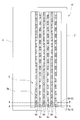
- FIG. 2 is a view of the turbine blade according to the first embodiment of the present invention as seen from the abdomen side and omitting the abdomen.
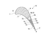
- 3 is a cross-sectional view taken along line AA in FIG. 4 is a cross-sectional view taken along line BB in FIG.
- FIG. 5 is a schematic view of a ventral protrusion and a back protrusion provided in the turbine blade according to the first embodiment of the present invention as seen from the height direction of the turbine blade.
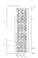
- FIG. 6 is an arrow view of the turbine blade according to the second embodiment of the present invention as viewed from the ventral side and omitting the abdomen.
- FIG. 1 is a perspective view showing a configuration of a turbine blade in the first embodiment of the present invention.
- FIG. 2 is a view of the turbine blade according to the first embodiment of the present invention as seen from the abdomen side and omitting the abdomen.
- 3
- FIG. 7 is a schematic view of the ventral side protrusion and the back side protrusion provided in the turbine blade according to the second embodiment of the present invention as seen from the height direction of the turbine blade.
- FIG. 8 is an arrow view of the turbine blade according to the third embodiment of the present invention as viewed from the ventral side and omitting the abdominal part.
- FIG. 9 is a schematic view of the ventral side protrusion and the back side protrusion included in the turbine blade according to the third embodiment of the present invention as seen from the height direction of the turbine blade.
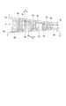
- FIG. 10 is an arrow view of the turbine blade according to the fourth embodiment of the present invention as viewed from the ventral side and the abdomen is omitted.
- FIG. 1 is a perspective view showing a configuration of a turbine blade 10 of the present embodiment.
- the turbine blade 10 shown in FIG. 1 is a turbine blade formed of metal, but the turbine blade of the present invention is not limited to a turbine blade, and can be applied to a turbine stationary blade. .
- the turbine blade 10 is exposed to a fluid flowing from the front edge portion 1 toward the rear edge portion 2, and is abdomen 3 that is curved so as to be recessed in front of the paper surface, and a back portion 4 that is curved so as to swell on the back side of the paper surface. have.
- the direction (indicated by arrows in FIG. 1) connecting the hub side, which is the inner diameter side with respect to the rotating shaft of the turbine, and the tip side, which is the outer diameter side with respect to the rotating shaft is the height direction of the turbine blades.
- the hub side which is the inner diameter side with respect to the rotating shaft of the turbine
- the tip side which is the outer diameter side with respect to the rotating shaft
- the turbine blade 10 includes a hollow region 5 inside and a plurality of meandering channels 6 formed in the hollow region 5.
- the hollow region 5 is an internal space of the turbine blade 10 formed from a substantially central portion in the direction from the front edge portion 1 to the rear edge portion 2 to the vicinity of the rear edge portion 2.
- a supply flow path 7 for supplying a cooling gas to the hollow region 5 is connected to the front edge 1 side of the hollow region 5.
- the rear edge 2 side of the hollow region 5 is an opening end 51 formed toward the rear edge 2.
- the meandering channel 6 causes the cooling gas supplied to the hollow region 5 through the supply channel 7 to meander repeatedly between the back side wall surface 5b and the abdominal side wall surface 5a (see FIG. 3), thereby leading the front edge 1 side. It leads toward the rear edge portion 2 side (rear edge side) from the (front edge side).
- a plurality of meandering channels 6 are continuously arranged in the height direction of the turbine blade 10, and the adjacent meandering channels are cooled by different repeating patterns (meandering patterns). Let the gas meander. Specifically, in the turbine blade 10 of the present embodiment, the repeating patterns of the adjacent meandering channels 6 are shifted in the same cycle and the phase is shifted by a half cycle.
- FIG. 2 is an arrow view in which the abdomen 3 is omitted while the turbine blade 10 is viewed from the abdominal side.
- FIG. 3 is a cross-sectional view taken along the line AA in FIG. 2, and is a cross-sectional view of the serpentine flow path 6a on the hub side of two adjacent meandering flow paths 6.
- FIG. 4 is a cross-sectional view taken along the line BB in FIG. 2, and is a cross-sectional view of the meandering flow path 6b on the chip side among two adjacent meandering flow paths 6.
- the meandering flow path 6 includes a ventral protrusion 6 c that protrudes from the abdominal wall surface 5 a in the hollow region 5 and has a distal end surface that is separated from the back side wall surface 5 b, and a back in the hollow region 5.
- the rear side protruding portions 6d that protrude from the side wall surface 5b and whose front end surface is separated from the abdominal side wall surface 5a are alternately arranged.
- FIG. 2 shows a plurality of points on the ventral protrusion 6c and the back protrusion 6d that constitute the meandering flow path 6a.
- the ventral protrusion 6c and the back protrusion 6d constituting the meandering flow path 6b are shown without a dot.
- the back side protrusion part 6d which comprises the meandering flow path 6b is filled and shown.
- FIG. 2 is an arrow view in which the abdomen 3 is omitted while the turbine blade 10 is viewed from the abdomen as described above, and the surface of the abdomen protrusion 6c connected to the abdomen 3 is shown with hatching.
- the arrangement interval between the abdominal projection 6c and the dorsal projection 6d is set equal in the meandering channel 6a and the meandering channel 6b (that is, adjacent meandering flow).
- the repetitive pattern of the path 6 has the same period), and further, the ventral protrusions 6c and the back protrusions 6d are alternately arranged in the height direction of the turbine blades 10 (that is, adjacent meandering channels 6).
- the phase of the repetitive pattern is shifted by half a cycle).
- FIG. 5 is a schematic view of the ventral protrusion 6 c and the back protrusion 6 d as viewed from the height direction of the turbine blade 10. And as shown in this figure, the abdominal side protrusion part 6c and the back
- the cooling gas supplied to the hollow region 5 via the supply flow path 7 flows from the front edge side to the rear edge side, and the back wall surface in the meandering flow path 6. After being meandered repeatedly between 5b and the abdominal wall surface 5a, it is discharged outside.
- the repeating pattern of the meandering channel 6a and the repeating pattern of the meandering channel 6b adjacent to the meandering channel 6a are shifted in phase by a half cycle. . Therefore, as shown in FIG. 5, when the cooling gas Y1 flows from the back side wall surface 5b toward the abdominal wall surface 5a in the meandering channel 6a, the abdominal side wall surface 5a and the back side wall surface 5b in the serpentine channel 6b. The cooling gas Y2 flows toward.
- a plurality of meandering flow paths 6 are continuously arranged in the height direction of the turbine blade 10, and adjacent meandering flow paths 6 meander the cooling gas in different repeating patterns.
- the arrangement patterns of the ventral protrusions 6c and the back protrusions 6d are different in the adjacent meandering flow paths 6.
- the abdominal projection 6c and the dorsal projection 6d are discretely arranged in the height direction of the turbine blade 10, and the back side wall surface or the abdominal side wall surface is separated as in the conventional turbine blade. It is not necessary to provide a slot portion that is held and extends long in the height direction.
- the core used for manufacturing such a turbine blade it is not necessary to form a protrusion that extends long in a straight line in the height direction on the surface corresponding to the abdominal wall surface. That is, it is not necessary to form a particularly fragile portion in the conventional core. Therefore, for example, in the case where the core is allowed to have the same degree of brittleness as in the prior art, it is possible to make the core finer, for example, by narrowing the interval between the protrusions in the core.
- a structure that increases the rigidity of the core is proposed, the degree of freedom in designing the internal structure is increased, and the optimum structure is used, thereby cooling the turbine blade. Efficiency can be further improved.
- FIG. 6 is an arrow view in which the abdomen 3 is omitted while the turbine blade 10 of this embodiment is viewed from the abdomen side.
- FIG. 7 is a schematic view of the ventral protrusion 6 c and the back protrusion 6 d provided in the turbine blade 10 as viewed from the height direction of the turbine blade 10.
- the repeating patterns of the adjacent meandering flow paths 6a and 6b have the same period and the phase is shifted by a quarter period.
- a meandering flow is formed between the ventral protrusion 6c and the back protrusion 6d of the meandering passage 6a.
- the ventral protrusion 6c and the dorsal protrusion 6d of the path 6b are arranged.
- FIG. 8 is an arrow view in which the abdomen 3 is omitted while the turbine blade 10 of this embodiment is viewed from the abdomen side.
- FIG. 9 is a schematic view of the ventral protrusion 6 c and the back protrusion 6 d provided in the turbine blade 10 as viewed from the height direction of the turbine blade 10.
- the repeating pattern of the adjacent meandering channels 6a and 6b has the same period and the phase is shifted by a quarter period, and further, the ventral protrusion 6c.
- the width of the back projecting portion 6d is the width d of the flow path from the back side wall surface 5b of the meandering flow path 6 to the abdominal side wall face 5a and the flow path from the abdominal side wall face 5a of the meandering flow path 6 to the back side wall face 5b.
- FIG. 10 is a view of the turbine blade 10 of the present embodiment as viewed from the abdomen side and omitting the abdomen 3.
- the turbine blade 10 of this embodiment includes the meandering flow path 6 (meandering flow path 61) of the first embodiment in the area A on the tip side of the hollow area 5, and the center of the hollow area 5
- the region B is provided with the meandering channel 6 (meandering channel 62) of the second embodiment
- the region C on the hub side of the hollow region 5 is provided with the meandering channel 6 (meandering channel 63) of the third embodiment. ing.
- the cooling efficiency varies depending on the region in the height direction, and cooling according to the heating state of the turbine blade 10 can be realized.
- the repeating pattern of the meandering channel 6 shown in the above embodiment that is, the arrangement pattern of the back side wall surface 5b and the abdominal side wall surface 5a is an example, and can be arbitrarily changed according to the cooling performance required for the turbine blade. .
Landscapes
- Engineering & Computer Science (AREA)
- Mechanical Engineering (AREA)
- General Engineering & Computer Science (AREA)
- Chemical & Material Sciences (AREA)
- Combustion & Propulsion (AREA)
- Turbine Rotor Nozzle Sealing (AREA)
Abstract
Description
本願は、2009年10月16日に日本国に出願された特願2009-239124号に基づき優先権を主張し、その内容をここに援用する。
このような対策の1つに、タービン翼を中空に形成し、この中空領域に冷却ガスを供給することによってタービン翼の過熱を抑制する方法がある。その冷却方式の一つにインピンジ冷却方式がある。インピンジ冷却方式は高い冷却性能が得られる冷却方式として知られているが、インサートと呼ばれる部品を翼内部に挿入する必要があるため、インピンジ冷却方式を用いる場合は、翼形状が制限される。現在の空力設計では翼素性能を高めるために、複雑な三次元形状となることが一般的であり、インサートを挿入可能なように翼形状を制限されることは、空力設計の観点から見てデメリットとなる。
具体的には、タービン翼の前縁側から後縁側に向けて冷却ガスを導く過程において、冷却ガスを背側壁面と腹側壁面との間において繰り返し蛇行させることによって冷却効率を向上させる構成が、特許文献1に開示されている。
そして、このようなスロット部は、腹側壁面あるいは背側壁面のいずれか一方に片持ちされた状態で、かつ、タービン翼の高さ方向(ハブ側とチップ側とを結ぶ方向)に長く延在して形成されている。
しかしながら、中子は、セラミックス等によって形成され、上記突出部は、タービン翼の背側壁面に相当する面あるいはタービン翼の腹側壁面に相当する面に片持ち状態でタービンの高さ方向に長く延在しているため、特に曲がり部に応力がかかりやすい。
したがって、中子強度の観点から形状の制約を受ける可能性がある。また、製造可能であったとしても中子の歩留まりが悪くなる可能性がある。
つまり、本発明によれば、隣り合う蛇行流路において、背側壁面あるいは腹側壁面から突出される突出部(スロット部)の配置パターンが、異なることとなる。このため、突出部がタービン翼の高さ方向において離散化して配置されることとなり、従来のタービン翼のように、背側壁面あるいは腹側壁面に片持ちされると共に高さ方向に長く延在するスロット部を備える必要がなくなる。
したがって、このようなタービン翼の製造に用いられる中子において、腹側壁面に相当する面に高さ方向に一直線で長く延在する突出部を形成する必要がなくなる。すなわち、従来の中子のうち、特に脆い箇所を形成する必要がなくなる。よって、例えば、従来と同じ程度の脆性を中子に許容する場合には、より中子における突出部間隔を狭める等の微細化が可能となる。
このように、本発明によれば、中子の剛性を高めるような構造を提案し、内部構造の設計自由度を高め、最適な構造を用いることにより、ひいてはタービン翼の冷却効率をより向上させることが可能となる。
図1は、本実施形態のタービン翼10の構成を示す斜視図である。
なお、図1に示すタービン翼10は、金属によって形成されるタービン動翼であるが、本発明のタービン翼はタービン動翼に限られるものではなく、タービン静翼に適用することも可能である。
タービン翼10は、前縁部1から後縁部2に向けて流れる流体中に晒され、紙面手前において凹むように湾曲された腹部3と、紙面奥側において膨らむように湾曲された背部4とを有している。なお、図1において、タービンの回転軸に対して内径側であるハブ側と回転軸に対して外径側のチップ側とを結ぶ方向(図1に矢印で表示)をタービン翼の高さ方向とする。
中空領域5は、前縁部1から後縁部2に向かう方向における略中央部から後縁部2の近傍まで形成されたタービン翼10の内部空間である。この中空領域5の前縁部1側には、中空領域5に冷却ガスを供給するための供給流路7が接続されている。また、中空領域5の後縁部2側は、後縁部2に向けて形成された開口端51とされている。
具体的には、本実施形態のタービン翼10においては、隣り合う蛇行流路6の繰り返しパターンが同周期で位相が半周期ずらされている。
なお、視認を容易とするために、図2(後の図5も同様)においては、蛇行流路6aを構成する腹側突出部6cと背側突出部6dとに複数の点を入れて示し、蛇行流路6bを構成する腹側突出部6cと背側突出部6dとには点を入れずに示している。また、蛇行流路6bを構成する背側突出部6dは、塗りつぶして示している。
そして、図2~図4に示すように、腹側突出部6cと背側突出部6dとの配置間隔が蛇行流路6aと蛇行流路6bとにおいて等しく設定されており(すなわち隣り合う蛇行流路6の繰り返しパターンが同周期とされている)、さらに腹側突出部6cと背側突出部6dとがタービン翼10の高さ方向に交互に設置されている(すなわち隣り合う蛇行流路6の繰り返しパターンの位相が半周期ずらされている)。
このため、図5に示すように、蛇行流路6aにおいて背側壁面5bから腹側壁面5aに向けて冷却ガスY1が流れる場合には、蛇行流路6bにおいて腹側壁面5aから背側壁面5bに向けて冷却ガスY2が流れる。一方、蛇行流路6aにおいて腹側壁面5aから背側壁面5bに向けて冷却ガスY1が流れる場合には、蛇行流路6bにおいて背側壁面5bから腹側壁面5aに向けて冷却ガスが流れる。
つまり、本実施形態のタービン翼10によれば、隣り合う蛇行流路6において、腹側突出部6cと背側突出部6dとの配置パターンが、異なることとなる。このため、腹側突出部6cと背側突出部6dとがタービン翼10の高さ方向において離散化して配置されることとなり、従来のタービン翼のように、背側壁面あるいは腹側壁面に片持ちされると共に高さ方向に長く延在するスロット部を備える必要がなくなる。
したがって、このようなタービン翼の製造に用いられる中子において、腹側壁面に相当する面に高さ方向に一直線で長く延在する突出部を形成する必要がなくなる。すなわち、従来の中子のうち、特に脆い箇所を形成する必要がなくなる。よって、例えば、従来と同じ程度の脆性を中子に許容する場合には、より中子における突出部間隔を狭める等の微細化が可能となる。
このように、本実施形態のタービン翼10によれば、中子の剛性を高めるような構造を提案し、内部構造の設計自由度を高め、最適な構造を用いることにより、ひいてはタービン翼の冷却効率をより向上させることが可能となる。
次に、本発明の第2実施形態について説明する。なお、本実施形態の説明において、上記第1実施形態と同様の部分については、その説明を省略あるいは簡略化する。
このような構成を採用することによって、図7に示すように、タービン翼10の高さ方向から見て、蛇行流路6aの腹側突出部6cと背側突出部6dと間に、蛇行流路6bの腹側突出部6cと背側突出部6dとが配置されることとなる。
次に、本発明の第3実施形態について説明する。なお、本実施形態の説明においては、上記第1、2実施形態と同様の部分については、その説明を省略あるいは簡略化する。
このような構成を採用することによって、図9に示すように、タービン翼10の高さ方向から見て、蛇行流路6aの腹側突出部6cと背側突出部6dと間に、蛇行流路6bの腹側突出部6cと背側突出部6dとが重ねて配置されることとなる。
したがって、本実施形態のタービン翼10によれば、隣り合う蛇行流路6a,6b間において冷却ガスが移動することを抑制することができるため、冷却ガスの偏りを抑制することができ、確実にタービン翼10全体を冷却することが可能となる。
次に、本発明の第4実施形態について説明する。なお、本第4実施形態の説明において、上記第1~第3実施形態と同様の部分については、その説明を省略あるいは簡略化する。
この図に示すように、本実施形態のタービン翼10は、中空領域5のチップ側の領域Aに上記第1実施形態の蛇行流路6(蛇行流路61)を備え、中空領域5の中央領域Bに上記第2実施形態の蛇行流路6(蛇行流路62)を備え、中空領域5のハブ側の領域Cに上記第3実施形態の蛇行流路6(蛇行流路63)を備えている。
1……前縁部
2……後縁部
3……腹部
4……背部
5……中空領域
5a……腹側壁面
5b……背側壁面
6(6a,6b)……蛇行流路
6c……腹側突出部(突出部)
6d……背側突出部(突出部)
Y1,Y2……冷却ガス
Claims (4)
- 中空領域に供給される冷却ガスによって冷却可能なタービン翼であって、
冷却ガスを背側壁面と腹側壁面との間において繰り返し蛇行させて導く蛇行流路がハブ側からチップ側に向けて連続して複数配列され、隣り合う前記蛇行流路が異なる繰り返しパターンにて前記冷却ガスを蛇行させるタービン翼。 - 隣り合う前記蛇行流路の繰り返しパターンが同周期で位相が半周期ずれている請求項1記載のタービン翼。
- 隣り合う前記蛇行流路の繰り返しパターンが同周期で位相が4分の1周期ずれている請求項1記載のタービン翼。
- 前記蛇行流路を構成する壁部の一部であり前記背側壁面と腹側壁面から突出する突出部の幅が、前記蛇行流路の前記背側壁面から前記腹側壁面に向かう流路の幅及び前記蛇行流路の前記腹側壁面から前記背側壁面に向かう流路の幅よりも広く設定されている請求項1~3いずれかに記載のタービン翼。
Priority Applications (4)
| Application Number | Priority Date | Filing Date | Title |
|---|---|---|---|
| EP10823331.3A EP2489835B1 (en) | 2009-10-16 | 2010-10-07 | Turbine blade |
| CN201080046021.7A CN102575523B (zh) | 2009-10-16 | 2010-10-07 | 涡轮叶片 |
| KR1020127009099A KR101555049B1 (ko) | 2009-10-16 | 2010-10-07 | 터빈 날개 |
| US13/501,519 US9194236B2 (en) | 2009-10-16 | 2010-10-07 | Turbine blade |
Applications Claiming Priority (2)
| Application Number | Priority Date | Filing Date | Title |
|---|---|---|---|
| JP2009239124A JP2011085084A (ja) | 2009-10-16 | 2009-10-16 | タービン翼 |
| JP2009-239124 | 2009-10-16 |
Publications (1)
| Publication Number | Publication Date |
|---|---|
| WO2011046063A1 true WO2011046063A1 (ja) | 2011-04-21 |
Family
ID=43876114
Family Applications (1)
| Application Number | Title | Priority Date | Filing Date |
|---|---|---|---|
| PCT/JP2010/067659 Ceased WO2011046063A1 (ja) | 2009-10-16 | 2010-10-07 | タービン翼 |
Country Status (6)
| Country | Link |
|---|---|
| US (1) | US9194236B2 (ja) |
| EP (1) | EP2489835B1 (ja) |
| JP (1) | JP2011085084A (ja) |
| KR (1) | KR101555049B1 (ja) |
| CN (1) | CN102575523B (ja) |
| WO (1) | WO2011046063A1 (ja) |
Families Citing this family (10)
| Publication number | Priority date | Publication date | Assignee | Title |
|---|---|---|---|---|
| US9435208B2 (en) * | 2012-04-17 | 2016-09-06 | General Electric Company | Components with microchannel cooling |
| KR102138327B1 (ko) * | 2013-11-15 | 2020-07-27 | 한화에어로스페이스 주식회사 | 터빈 |
| CN108779678B (zh) * | 2016-03-22 | 2021-05-28 | 西门子股份公司 | 具有后缘框架特征的涡轮翼型件 |
| JP6898104B2 (ja) * | 2017-01-18 | 2021-07-07 | 川崎重工業株式会社 | タービン翼の冷却構造 |
| JP6860383B2 (ja) * | 2017-03-10 | 2021-04-14 | 川崎重工業株式会社 | タービン翼の冷却構造 |
| US11149550B2 (en) * | 2019-02-07 | 2021-10-19 | Raytheon Technologies Corporation | Blade neck transition |
| US10871074B2 (en) | 2019-02-28 | 2020-12-22 | Raytheon Technologies Corporation | Blade/vane cooling passages |
| CN112177682B (zh) * | 2020-09-29 | 2021-08-10 | 大连理工大学 | 一种采用波浪式隔肋的涡轮叶片尾缘劈缝冷却结构 |
| US11603765B1 (en) | 2021-07-16 | 2023-03-14 | Raytheon Technologies Corporation | Airfoil assembly with fiber-reinforced composite rings and toothed exit slot |
| US11549378B1 (en) | 2022-06-03 | 2023-01-10 | Raytheon Technologies Corporation | Airfoil assembly with composite rings and sealing shelf |
Citations (6)
| Publication number | Priority date | Publication date | Assignee | Title |
|---|---|---|---|---|
| US4407632A (en) * | 1981-06-26 | 1983-10-04 | United Technologies Corporation | Airfoil pedestaled trailing edge region cooling configuration |
| JPH10311203A (ja) * | 1997-02-20 | 1998-11-24 | Westinghouse Electric Corp <We> | ターボ機械に使用するための翼部及びその製造方法 |
| JP2002516944A (ja) * | 1998-05-25 | 2002-06-11 | エービービー アクチボラゲット | ガスタービン用要素 |
| US7255535B2 (en) * | 2004-12-02 | 2007-08-14 | Albrecht Harry A | Cooling systems for stacked laminate CMC vane |
| WO2007094212A1 (ja) | 2006-02-14 | 2007-08-23 | Ihi Corporation | 冷却構造 |
| JP2009239124A (ja) | 2008-03-27 | 2009-10-15 | Furukawa Electric Co Ltd:The | ウェハ表面保護テープ |
Family Cites Families (11)
| Publication number | Priority date | Publication date | Assignee | Title |
|---|---|---|---|---|
| US4203706A (en) | 1977-12-28 | 1980-05-20 | United Technologies Corporation | Radial wafer airfoil construction |
| US4752186A (en) * | 1981-06-26 | 1988-06-21 | United Technologies Corporation | Coolable wall configuration |
| DE4430302A1 (de) | 1994-08-26 | 1996-02-29 | Abb Management Ag | Prallgekühltes Wandteil |
| DE50304226D1 (de) * | 2002-03-25 | 2006-08-24 | Alstom Technology Ltd | Gekühlte turbinenschaufel |
| US6742991B2 (en) * | 2002-07-11 | 2004-06-01 | Mitsubishi Heavy Industries, Ltd. | Turbine blade and gas turbine |
| US7114916B2 (en) | 2004-02-09 | 2006-10-03 | United Technologies Corporation | Tailored turbulation for turbine blades |
| US7438527B2 (en) * | 2005-04-22 | 2008-10-21 | United Technologies Corporation | Airfoil trailing edge cooling |
| US7296973B2 (en) * | 2005-12-05 | 2007-11-20 | General Electric Company | Parallel serpentine cooled blade |
| US7713026B1 (en) | 2007-03-06 | 2010-05-11 | Florida Turbine Technologies, Inc. | Turbine bladed with tip cooling |
| US7785070B2 (en) * | 2007-03-27 | 2010-08-31 | Siemens Energy, Inc. | Wavy flow cooling concept for turbine airfoils |
| GB2452327B (en) * | 2007-09-01 | 2010-02-03 | Rolls Royce Plc | A cooled component |
-
2009
- 2009-10-16 JP JP2009239124A patent/JP2011085084A/ja active Pending
-
2010
- 2010-10-07 US US13/501,519 patent/US9194236B2/en active Active
- 2010-10-07 KR KR1020127009099A patent/KR101555049B1/ko not_active Expired - Fee Related
- 2010-10-07 CN CN201080046021.7A patent/CN102575523B/zh not_active Expired - Fee Related
- 2010-10-07 WO PCT/JP2010/067659 patent/WO2011046063A1/ja not_active Ceased
- 2010-10-07 EP EP10823331.3A patent/EP2489835B1/en active Active
Patent Citations (6)
| Publication number | Priority date | Publication date | Assignee | Title |
|---|---|---|---|---|
| US4407632A (en) * | 1981-06-26 | 1983-10-04 | United Technologies Corporation | Airfoil pedestaled trailing edge region cooling configuration |
| JPH10311203A (ja) * | 1997-02-20 | 1998-11-24 | Westinghouse Electric Corp <We> | ターボ機械に使用するための翼部及びその製造方法 |
| JP2002516944A (ja) * | 1998-05-25 | 2002-06-11 | エービービー アクチボラゲット | ガスタービン用要素 |
| US7255535B2 (en) * | 2004-12-02 | 2007-08-14 | Albrecht Harry A | Cooling systems for stacked laminate CMC vane |
| WO2007094212A1 (ja) | 2006-02-14 | 2007-08-23 | Ihi Corporation | 冷却構造 |
| JP2009239124A (ja) | 2008-03-27 | 2009-10-15 | Furukawa Electric Co Ltd:The | ウェハ表面保護テープ |
Also Published As
| Publication number | Publication date |
|---|---|
| EP2489835A4 (en) | 2015-08-26 |
| CN102575523B (zh) | 2016-01-20 |
| US20120201694A1 (en) | 2012-08-09 |
| JP2011085084A (ja) | 2011-04-28 |
| CN102575523A (zh) | 2012-07-11 |
| KR101555049B1 (ko) | 2015-09-22 |
| EP2489835A1 (en) | 2012-08-22 |
| US9194236B2 (en) | 2015-11-24 |
| EP2489835B1 (en) | 2019-08-28 |
| KR20120056868A (ko) | 2012-06-04 |
Similar Documents
| Publication | Publication Date | Title |
|---|---|---|
| CN102575523B (zh) | 涡轮叶片 | |
| JP4929097B2 (ja) | ガスタービン翼 | |
| JP6231071B2 (ja) | 冷却式の壁 | |
| EP2558686B1 (en) | Blade or vane for a turbomachine | |
| CN101769170B (zh) | 涡轮叶片冷却回路 | |
| JP5916047B2 (ja) | シールド冷却媒体供給通路を備えたタービンブレード | |
| JP6066065B2 (ja) | 伝熱装置を備えたガスタービン燃焼器 | |
| JP5852208B2 (ja) | 翼部材及び回転機械 | |
| KR102216813B1 (ko) | 터빈 날개 및 가스 터빈 | |
| JP2015127532A (ja) | タービンブレード内の構造構成および冷却回路 | |
| WO2012124215A1 (ja) | ガスタービン動翼およびガスタービン | |
| JP2015105656A (ja) | 壁近傍のマイクロサーキット縁部冷却を有するタービンブレード | |
| JP6496543B2 (ja) | タービンブレードの内部冷却回路 | |
| JP6506549B2 (ja) | タービンブレード内の構造構成および冷却回路 | |
| WO2009139374A1 (ja) | ガスタービン翼およびこれを備えたガスタービン | |
| US9739155B2 (en) | Structural configurations and cooling circuits in turbine blades | |
| JP5916294B2 (ja) | ガスタービン動翼及びその製造方法 | |
| JP5390163B2 (ja) | ターボ機械用の冷却ブレード | |
| JP5545401B2 (ja) | タービン翼 | |
| US20110033311A1 (en) | Turbine Airfoil Cooling System with Pin Fin Cooling Chambers | |
| JP6910607B2 (ja) | ピンフィン、ピンフィン群及びタービン翼 | |
| EP3417153B1 (en) | Turbine blade having an airfoil with trailing edge framing features | |
| JP5317014B2 (ja) | タービン翼 | |
| WO2017095438A1 (en) | Turbine airfoil with biased trailing edge cooling arrangement | |
| JP2006214324A (ja) | フィルム冷却翼 |
Legal Events
| Date | Code | Title | Description |
|---|---|---|---|
| WWE | Wipo information: entry into national phase |
Ref document number: 201080046021.7 Country of ref document: CN |
|
| 121 | Ep: the epo has been informed by wipo that ep was designated in this application |
Ref document number: 10823331 Country of ref document: EP Kind code of ref document: A1 |
|
| ENP | Entry into the national phase |
Ref document number: 20127009099 Country of ref document: KR Kind code of ref document: A |
|
| WWE | Wipo information: entry into national phase |
Ref document number: 13501519 Country of ref document: US |
|
| NENP | Non-entry into the national phase |
Ref country code: DE |
|
| WWE | Wipo information: entry into national phase |
Ref document number: 2010823331 Country of ref document: EP |