WO2011048721A1 - 冷凍空調装置 - Google Patents
冷凍空調装置 Download PDFInfo
- Publication number
- WO2011048721A1 WO2011048721A1 PCT/JP2010/002866 JP2010002866W WO2011048721A1 WO 2011048721 A1 WO2011048721 A1 WO 2011048721A1 JP 2010002866 W JP2010002866 W JP 2010002866W WO 2011048721 A1 WO2011048721 A1 WO 2011048721A1
- Authority
- WO
- WIPO (PCT)
- Prior art keywords
- refrigerant
- extension pipe
- internal volume
- operation data
- amount
- Prior art date
- Legal status (The legal status is an assumption and is not a legal conclusion. Google has not performed a legal analysis and makes no representation as to the accuracy of the status listed.)
- Ceased
Links
Images


Classifications
-
- F—MECHANICAL ENGINEERING; LIGHTING; HEATING; WEAPONS; BLASTING
- F25—REFRIGERATION OR COOLING; COMBINED HEATING AND REFRIGERATION SYSTEMS; HEAT PUMP SYSTEMS; MANUFACTURE OR STORAGE OF ICE; LIQUEFACTION SOLIDIFICATION OF GASES
- F25B—REFRIGERATION MACHINES, PLANTS OR SYSTEMS; COMBINED HEATING AND REFRIGERATION SYSTEMS; HEAT PUMP SYSTEMS
- F25B49/00—Arrangement or mounting of control or safety devices
- F25B49/005—Arrangement or mounting of control or safety devices of safety devices
-
- F—MECHANICAL ENGINEERING; LIGHTING; HEATING; WEAPONS; BLASTING
- F24—HEATING; RANGES; VENTILATING
- F24F—AIR-CONDITIONING; AIR-HUMIDIFICATION; VENTILATION; USE OF AIR CURRENTS FOR SCREENING
- F24F11/00—Control or safety arrangements
- F24F11/30—Control or safety arrangements for purposes related to the operation of the system, e.g. for safety or monitoring
- F24F11/32—Responding to malfunctions or emergencies
- F24F11/36—Responding to malfunctions or emergencies to leakage of heat-exchange fluid
-
- F—MECHANICAL ENGINEERING; LIGHTING; HEATING; WEAPONS; BLASTING
- F25—REFRIGERATION OR COOLING; COMBINED HEATING AND REFRIGERATION SYSTEMS; HEAT PUMP SYSTEMS; MANUFACTURE OR STORAGE OF ICE; LIQUEFACTION SOLIDIFICATION OF GASES
- F25B—REFRIGERATION MACHINES, PLANTS OR SYSTEMS; COMBINED HEATING AND REFRIGERATION SYSTEMS; HEAT PUMP SYSTEMS
- F25B2345/00—Details for charging or discharging refrigerants; Service stations therefor
- F25B2345/003—Control issues for charging or collecting refrigerant to or from a cycle
-
- F—MECHANICAL ENGINEERING; LIGHTING; HEATING; WEAPONS; BLASTING
- F25—REFRIGERATION OR COOLING; COMBINED HEATING AND REFRIGERATION SYSTEMS; HEAT PUMP SYSTEMS; MANUFACTURE OR STORAGE OF ICE; LIQUEFACTION SOLIDIFICATION OF GASES
- F25B—REFRIGERATION MACHINES, PLANTS OR SYSTEMS; COMBINED HEATING AND REFRIGERATION SYSTEMS; HEAT PUMP SYSTEMS
- F25B2400/00—General features or devices for refrigeration machines, plants or systems, combined heating and refrigeration systems or heat-pump systems, i.e. not limited to a particular subgroup of F25B
- F25B2400/13—Economisers
-
- F—MECHANICAL ENGINEERING; LIGHTING; HEATING; WEAPONS; BLASTING
- F25—REFRIGERATION OR COOLING; COMBINED HEATING AND REFRIGERATION SYSTEMS; HEAT PUMP SYSTEMS; MANUFACTURE OR STORAGE OF ICE; LIQUEFACTION SOLIDIFICATION OF GASES
- F25B—REFRIGERATION MACHINES, PLANTS OR SYSTEMS; COMBINED HEATING AND REFRIGERATION SYSTEMS; HEAT PUMP SYSTEMS
- F25B2500/00—Problems to be solved
- F25B2500/19—Calculation of parameters
-
- F—MECHANICAL ENGINEERING; LIGHTING; HEATING; WEAPONS; BLASTING
- F25—REFRIGERATION OR COOLING; COMBINED HEATING AND REFRIGERATION SYSTEMS; HEAT PUMP SYSTEMS; MANUFACTURE OR STORAGE OF ICE; LIQUEFACTION SOLIDIFICATION OF GASES
- F25B—REFRIGERATION MACHINES, PLANTS OR SYSTEMS; COMBINED HEATING AND REFRIGERATION SYSTEMS; HEAT PUMP SYSTEMS
- F25B2500/00—Problems to be solved
- F25B2500/22—Preventing, detecting or repairing leaks of refrigeration fluids
- F25B2500/222—Detecting refrigerant leaks
-
- F—MECHANICAL ENGINEERING; LIGHTING; HEATING; WEAPONS; BLASTING
- F25—REFRIGERATION OR COOLING; COMBINED HEATING AND REFRIGERATION SYSTEMS; HEAT PUMP SYSTEMS; MANUFACTURE OR STORAGE OF ICE; LIQUEFACTION SOLIDIFICATION OF GASES
- F25B—REFRIGERATION MACHINES, PLANTS OR SYSTEMS; COMBINED HEATING AND REFRIGERATION SYSTEMS; HEAT PUMP SYSTEMS
- F25B2600/00—Control issues
- F25B2600/05—Refrigerant levels
-
- F—MECHANICAL ENGINEERING; LIGHTING; HEATING; WEAPONS; BLASTING
- F25—REFRIGERATION OR COOLING; COMBINED HEATING AND REFRIGERATION SYSTEMS; HEAT PUMP SYSTEMS; MANUFACTURE OR STORAGE OF ICE; LIQUEFACTION SOLIDIFICATION OF GASES
- F25B—REFRIGERATION MACHINES, PLANTS OR SYSTEMS; COMBINED HEATING AND REFRIGERATION SYSTEMS; HEAT PUMP SYSTEMS
- F25B2700/00—Sensing or detecting of parameters; Sensors therefor
- F25B2700/04—Refrigerant level
Definitions
- the present invention is a refrigeration air conditioner configured by connecting an outdoor unit that is a heat source and an indoor unit that is a user side via a refrigerant extension pipe, and has a high accuracy of the function of calculating the amount of refrigerant in the refrigerant circuit Concerning conversion.
- an extension pipe internal volume determination operation (in a cooling operation) Perform two operations with different densities in the refrigerant extension pipe), calculate the amount of refrigerant increase / decrease other than the refrigerant extension pipe between the two operating states, and divide the refrigerant increase / decrease amount by the refrigerant density change amount in the refrigerant extension pipe
- the internal volume of the refrigerant extension pipe is calculated, and the amount of refrigerant in the refrigerant extension pipe is calculated using the internal volume of the refrigerant extension pipe (see, for example, Patent Document 1).
- extension pipe internal volume determination operation is performed when calculating the extension pipe internal volume when the refrigeration air conditioner is installed. It is difficult to perform the extension pipe internal volume determination operation for the refrigeration air conditioner.
- the present invention has been made in view of such points, and can accurately calculate the internal volume of the refrigerant extension pipe using operation data obtained during normal operation, and can calculate the total refrigerant amount in the refrigerant circuit and detect refrigerant leakage. It aims at obtaining the refrigerating air-conditioner which can be performed with high precision.
- the refrigerating and air-conditioning apparatus uses, as operation data, a refrigerant circuit in which an outdoor unit that is a heat source unit and an indoor unit that is a usage-side unit are connected by a refrigerant extension pipe, and the temperature and pressure of the main part of the refrigerant circuit.
- operation data a refrigerant circuit in which an outdoor unit that is a heat source unit and an indoor unit that is a usage-side unit are connected by a refrigerant extension pipe, and the temperature and pressure of the main part of the refrigerant circuit.
- a reference refrigerant amount serving as a reference for judging refrigerant leakage from the refrigerant circuit is calculated.
- the total refrigerant amount in the refrigerant circuit is calculated based on the calculation unit, the internal volume of the refrigerant extension pipe calculated by the calculation unit, and the operation data measured by the measurement unit during normal operation, and the calculated total refrigerant amount And a determination unit that compares the reference refrigerant amount and determines whether or not there is a refrigerant leak.
- the internal volume of the refrigerant extension pipe can be calculated from the operation data at the time of normal operation without performing a special operation, not only in the case of newly installing the refrigeration air conditioner, but also for the existing refrigeration air conditioner. .
- the internal volume of the refrigerant extension pipe can be calculated with high accuracy. Calculation of the total refrigerant amount in the refrigeration air conditioner and refrigerant leakage detection can be performed with high accuracy.
- FIG. 2 is a ph diagram during cooling operation of the refrigeration air conditioning apparatus 1 according to Embodiment 1 of the present invention. It is a ph diagram at the time of heating operation of refrigeration air conditioner 1 concerning Embodiment 1 of the present invention.
- coolant leak detection method of the refrigeration air conditioning apparatus 1 which concerns on Embodiment 1 of this invention.
- It is a flowchart of the initial learning of the refrigeration air conditioning apparatus 1 which concerns on Embodiment 1 of this invention.
- Embodiment 1 FIG.
- an embodiment of a refrigerating and air-conditioning apparatus according to the present invention will be described based on the drawings.
- FIG. 1 is a configuration diagram of a refrigerating and air-conditioning apparatus 1 according to Embodiment 1 of the present invention.
- the refrigerating and air-conditioning apparatus 1 is an apparatus used for air conditioning in a room such as a building by performing a vapor compression refrigeration cycle operation.
- the refrigerating and air-conditioning apparatus 1 mainly includes an outdoor unit 2 as a heat source unit, a plurality of indoor units 4A and 4B (two in the present embodiment) connected in parallel thereto, and a liquid refrigerant extension pipe 6 And a gas refrigerant extension pipe 7.
- the liquid refrigerant extension pipe 6 is a pipe through which the liquid refrigerant passes by connecting the outdoor unit 2 and the indoor units 4A and 4B.
- the liquid main pipe 6A, the liquid branch pipes 6a and 6b, and the distributor 51a are connected. Configured.
- the gas refrigerant extension pipe 7 is a pipe through which the gas refrigerant passes by connecting the outdoor unit 2 and the indoor units 4A and 4B.
- the gas main pipe 7A, the gas branch pipes 7a and 7b, and the distributor 52a are connected to each other. Connected and configured.
- the indoor units 4A and 4B are installed by being embedded or suspended in a ceiling of a room such as a building, or by wall hanging or the like on a wall surface of the room.
- the indoor units 4A and 4B are connected to the outdoor unit 2 using the liquid refrigerant extension pipe 6 and the gas refrigerant extension pipe 7 and constitute a part of the refrigerant circuit 10.
- the configuration of the indoor unit 4B corresponds to a configuration in which a symbol B is attached instead of a symbol A indicating each part of the indoor unit 4A.
- the indoor unit 4A mainly has an indoor refrigerant circuit 10a (in the indoor unit 4B, the indoor refrigerant circuit 10b) that constitutes a part of the refrigerant circuit 10.
- This indoor refrigerant circuit 10a mainly has an expansion valve 41A as an expansion mechanism and an indoor heat exchanger 42A as a use side heat exchanger.
- the expansion valve 41A is an electric expansion valve connected to the liquid side of the indoor heat exchanger 42A in order to adjust the flow rate of the refrigerant flowing in the indoor refrigerant circuit 10a.
- the indoor heat exchanger 42A is a cross-fin type fin-and-tube heat exchanger composed of heat transfer tubes and a large number of fins, and functions as a refrigerant evaporator during cooling operation. It is a heat exchanger that cools indoor air and functions as a refrigerant condenser during heating operation to heat indoor air.
- the indoor unit 4A includes an indoor fan 43A as a blower fan for supplying indoor air as supply air after sucking indoor air into the unit and exchanging heat with the refrigerant in the indoor heat exchanger 42A.
- the indoor fan 43A is a fan capable of varying the air volume supplied to the indoor heat exchanger 42A.
- the indoor fan 43A is a centrifugal fan or a multiblade fan driven by a DC fan motor. It is.
- Gas side temperature sensors 33f and 33i for detecting the temperature of the refrigerant are provided on the gas side of the indoor heat exchangers 42A and 42B. Is provided. Liquid side temperature sensors 33e and 33h for detecting the refrigerant temperature Teo are provided on the liquid side of the indoor heat exchangers 42A and 42B.
- Indoor temperature sensors 33g and 33j for detecting the temperature of the indoor air flowing into the units are provided on the indoor air inlet side of the indoor units 4A and 4B.
- each of the temperature sensors 33e, 33f, 33g, 33h, 33i, and 33j is a thermistor.
- the indoor units 4A and 4B have indoor side control units 32a and 32b that control the operation of each unit constituting the indoor units 4A and 4B.
- the indoor side control parts 32a and 32b have the microcomputer, memory, etc. which were provided in order to control indoor unit 4A, 4B.
- the indoor side control units 32a and 32b exchange control signals and the like with a remote controller (not shown) for individually operating the indoor units 4A and 4B, and connect transmission lines with the outdoor unit 2. It is possible to exchange control signals and the like.
- the outdoor unit 2 is installed outside a building or the like, and is connected to the indoor units 4A and 4B through the liquid main pipe 6A, the liquid branch pipes 6a and 6b, the gas main pipe 7A, and the gas branch pipes 7a and 7b.
- the refrigerant circuit 10 is comprised between 4A and 4B.
- the outdoor unit 2 mainly has an outdoor refrigerant circuit 10 c that constitutes a part of the refrigerant circuit 10.
- the outdoor refrigerant circuit 10c mainly includes a compressor 21, a four-way valve 22, an outdoor heat exchanger 23, an accumulator 24, a supercooler 26, a liquid side closing valve 28, and a gas side closing valve 29. And have.
- the compressor 21 is a compressor whose operating capacity can be varied.
- the compressor 21 is a positive displacement compressor driven by a motor whose frequency F is controlled by an inverter.
- only one compressor 21 is provided, but the present invention is not limited to this, and two or more compressors may be connected in parallel according to the number of indoor units connected.
- the four-way valve 22 is a valve for switching the direction of refrigerant flow. During the cooling operation, the four-way valve 22 is switched as indicated by a solid line, and connects the discharge side of the compressor 21 and the gas side of the outdoor heat exchanger 23 and connects the accumulator 24 and the gas main pipe 7A side. . Thereby, the outdoor heat exchanger 23 functions as a condenser for the refrigerant compressed by the compressor 21, and the indoor heat exchangers 42A and 42B function as an evaporator.
- the four-way valve 22 is switched as indicated by the dotted line of the four-way valve, and connects the discharge side of the compressor 21 and the gas main pipe 7A and connects the accumulator 24 and the gas side of the outdoor heat exchanger 23. Connecting. Thereby, indoor heat exchanger 42A, 42B functions as a condenser of the refrigerant
- the outdoor heat exchanger 23 is a cross-fin type fin-and-tube heat exchanger composed of heat transfer tubes and a large number of fins. As described above, the outdoor heat exchanger 23 functions as a refrigerant condenser during the cooling operation, and functions as a refrigerant evaporator during the heating operation.
- the outdoor heat exchanger 23 has a gas side connected to the four-way valve 22 and a liquid side connected to the liquid main pipe 6A.
- the outdoor unit 2 has an outdoor fan 27 as a blower fan for sucking outdoor air into the unit, exchanging heat with the refrigerant in the outdoor heat exchanger 23, and then discharging the air outside.
- the outdoor fan 27 is a fan capable of changing the air volume of air supplied to the outdoor heat exchanger 23.
- the outdoor fan 27 is a propeller fan or the like driven by a motor including a DC fan motor.
- the accumulator 24 is connected between the four-way valve 22 and the compressor 21, and can store surplus refrigerant generated in the refrigerant circuit 10 in accordance with fluctuations in the operating load of the indoor units 4A and 4B. Container.
- the supercooler 26 is a double-pipe heat exchanger and is provided to cool the refrigerant sent to the expansion valves 41A and 41B after being condensed in the outdoor heat exchanger 23.
- the supercooler 26 is connected between the outdoor heat exchanger 23 and the liquid side shut-off valve 28 in this embodiment.
- a bypass circuit 71 is provided as a cooling source for the subcooler 26.
- a portion obtained by removing the bypass circuit 71 from the refrigerant circuit 10 is referred to as a main refrigerant circuit 10z.
- the bypass circuit 71 is connected to the main refrigerant circuit 10z so that a part of the refrigerant sent from the outdoor heat exchanger 23 to the expansion valves 41A and 41B is branched from the main refrigerant circuit 10z and returned to the suction side of the compressor 21. Yes. Specifically, the bypass circuit 71 branches a part of the refrigerant sent from the outdoor heat exchanger 23 to the expansion valves 41A and 41B from a position between the supercooler 26 and the liquid side closing valve 28, and the electric expansion valve It is connected to return to the suction side of the compressor 21 via a bypass flow rate adjustment valve 72 and the supercooler 26.
- the refrigerant sent from the outdoor heat exchanger 23 to the indoor expansion valves 41A and 41B is cooled by the refrigerant flowing through the bypass circuit 71 after being depressurized by the bypass flow rate adjusting valve 72 in the supercooler 26. That is, the capacity control of the subcooler 26 is performed by adjusting the opening degree of the bypass flow rate adjustment valve 72.
- the liquid side shut-off valve 28 and the gas side shut-off valve 29 are valves provided at connection ports with external devices and pipes (specifically, the liquid main pipe 6A and the gas main pipe 7A).
- the outdoor unit 2 is provided with a plurality of pressure sensors and temperature sensors.
- a suction pressure sensor 34a for detecting the suction pressure Ps of the compressor 21 and a discharge pressure sensor 34b for detecting the discharge pressure Pd of the compressor 21 are installed.
- the temperature sensor is a thermistor.
- an outdoor temperature sensor 33c As the temperature sensors, the suction temperature sensor 33a, the discharge temperature sensor 33b, the heat exchange temperature sensor 33k, the liquid side temperature sensor 33l, the liquid pipe temperature sensor 33d, and the bypass temperature sensor 33z. And an outdoor temperature sensor 33c.
- the suction temperature sensor 33 a is provided at a position between the accumulator 24 and the compressor 21 and detects the suction temperature Ts of the compressor 21.
- the discharge temperature sensor 33b detects the discharge temperature Td of the compressor 21.
- the heat exchanger temperature sensor 33k detects the temperature of the refrigerant flowing in the outdoor heat exchanger 23.
- the liquid side temperature sensor 33l is installed on the liquid side of the outdoor heat exchanger 23, and detects the refrigerant temperature on the liquid side of the outdoor heat exchanger 23.
- the liquid pipe temperature sensor 33d is installed at the outlet of the subcooler 26 on the main refrigerant circuit 10z side and detects the temperature of the refrigerant.
- the bypass temperature sensor 33z detects the temperature of the refrigerant flowing through the outlet of the supercooler 26 of the bypass circuit 71.
- the outdoor temperature sensor 33c is installed on the outdoor air inlet side of the outdoor unit 2 and detects the temperature of the outdoor air flowing into the unit.
- the outdoor unit 2 has an outdoor control unit 31 that controls the operation of each element constituting the outdoor unit 2.
- the outdoor side control part 31 has the microcomputer provided in order to control the outdoor unit 2, memory, an inverter circuit etc. which control a motor.
- the outdoor side control part 31 is comprised so that a control signal etc. may be exchanged via the transmission line between indoor side control part 32a, 32b of indoor unit 4A, 4B.
- the outdoor side control part 31 comprises the control part 3 which performs operation control of the whole refrigerating and air-conditioning apparatus 1 with the indoor side control parts 32a and 32b.
- FIG. 2 is a control block diagram of the refrigeration air conditioner 1 according to Embodiment 1 of the present invention.
- the control unit 3 is connected so as to receive detection signals from the pressure sensors 34a and 34b and the temperature sensors 33a to 33l and 33z.
- the control unit 3 also determines various devices (compressor 21, fan 27, fans 43A, 43B) and valves (four-way valve 22, flow control valve (liquid side closing valve 28, gas side closing valve) based on these detection signals and the like. 29, bypass flow rate adjusting valve 72) and expansion valves 41A, 41B) are connected to various devices and valves so that they can be controlled.
- the control unit 3 includes a measurement unit 3a, a calculation unit 3b, a storage unit 3c, a determination unit 3d, a drive unit 3e, a display unit 3f, an input unit 3g, and an output unit 3h.
- the measuring unit 3a is a part that measures information from the pressure sensors 34a and 34b and the temperature sensors 33a to 33l and 33z, and is a part that constitutes a measuring unit together with the pressure sensors 34a and 34b and the temperature sensors 33a to 33l and 33z.
- the calculation unit 3b is a part that calculates the internal refrigerant volume of the refrigerant extension pipe based on information measured by the measurement unit 3a and the like, and calculates a reference refrigerant amount that serves as a reference for determining refrigerant leakage from the refrigerant circuit 10.
- the storage unit 3c stores values measured by the measurement unit 3a and values calculated by the calculation unit 3b, stores internal volume data and initial filling amount described later, and stores information from the outside. It is.
- the determination unit 3d is a portion that compares the reference refrigerant amount stored in the storage unit 3c with the total refrigerant amount of the refrigerant circuit 10 calculated by calculation to determine whether or not there is refrigerant leakage.
- the drive unit 3e is a part that controls the compressor motor, valve, and fan motor, which are elements driven by the refrigeration air conditioner 1.
- the display unit 3f is a part for displaying information when the refrigerant charging is completed or when refrigerant leakage is detected, and for displaying the information to the outside or displaying an abnormality that occurs when the refrigeration air conditioner 1 is operated.
- the input unit 3g is a place for inputting and changing set values for various controls and for inputting external information such as a refrigerant charging amount.
- the output unit 3h is a part that outputs the measurement value measured by the measurement unit 3a and the value calculated by the calculation unit 3b to the outside.
- the output unit 3h may be a communication unit for communicating with an external device, and the refrigerating and air-conditioning apparatus 1 can transmit refrigerant leakage presence / absence data indicating the detection result of refrigerant leakage to a remote management center or the like via a communication line or the like. It is configured.
- the control unit 3 configured as described above performs the operation by switching between the cooling operation and the heating operation as the normal operation by the four-way valve 22, and according to the operation load of each of the indoor units 4A and 4B, Control of each device of the indoor units 4A and 4B is performed. Moreover, the control part 3 performs the refrigerant
- the refrigerant extension pipe is a pipe necessary for connecting the outdoor unit 2 and the indoor units 4A and 4B and circulating the refrigerant in the refrigeration air conditioner 1.
- the refrigerant extension pipe has a liquid refrigerant extension pipe 6 (liquid main pipe 6A, liquid branch pipes 6a, 6b) and a gas refrigerant extension pipe 7 (gas main pipe 7A, gas branch pipes 7a, 7b).
- This is a refrigerant pipe to be constructed on site when installing the building at the installation location such as a building.
- Refrigerant extension pipes each having a pipe diameter determined according to the combination of the outdoor unit 2 and the indoor units 4A and 4B are used.
- Refrigerant extension pipe length depends on local installation conditions. For this reason, the internal volume of the refrigerant extension pipe varies depending on the installation site, and cannot be input in advance at the time of shipment. Therefore, it is necessary to calculate the internal volume of the refrigerant extension pipe for each site. Details of the calculation method of the internal volume of the refrigerant extension pipe will be described later.
- distributors 51a and 52a and refrigerant extension pipes are used to connect one outdoor unit 2 and two indoor units 4A and 4B.
- the outdoor unit 2 and the distributor 51a are connected by a liquid main pipe 6A
- the distributor 51a and the indoor units 4A and 4B are connected by liquid branch pipes 6a and 6b.
- the indoor units 4A and 4B and the distributor 52a are connected by gas branch pipes 7a and 7b
- the distributor 52a and the outdoor unit 2 are connected by a gas main pipe 7A.
- the distributors 51a and 52a use T-shaped tubes, but the present invention is not limited thereto, and headers may be used.
- a plurality of indoor units are connected, a plurality of T-shaped tubes may be used for distribution, or a header may be used.
- the refrigerant circuit 10 is configured by connecting the indoor refrigerant circuits 10a and 10b, the outdoor refrigerant circuit 10c, and the refrigerant extension pipes (the liquid refrigerant extension pipe 6 and the gas refrigerant extension pipe 7). .
- the refrigerating and air-conditioning apparatus 1 has a refrigerant circuit 10 and a bypass circuit 71.
- the refrigerating and air-conditioning apparatus 1 according to the present embodiment is operated by switching the cooling operation and the heating operation by the four-way valve 22 by the control unit 3 including the indoor side control units 32a and 32b and the outdoor side control unit 31.
- the outdoor unit 2 and the indoor units 4A and 4B are controlled in accordance with the operation loads of the indoor units 4A and 4B.
- the refrigerating and air-conditioning apparatus 1 of the present embodiment performs a cooling operation or a heating operation as a normal operation, and controls the components of the outdoor unit 2 and the indoor units 4A and 4B according to the operation load of each indoor unit 4A and 4B. Do.
- the cooling operation and the heating operation will be described in this order.
- FIG. 3 is a ph diagram during the cooling operation of the refrigeration air-conditioning apparatus 1 according to Embodiment 1 of the present invention.
- the cooling operation will be described with reference to FIGS. 3 and 1.
- the four-way valve 22 is in the state indicated by the solid line in FIG. 1, that is, the discharge side of the compressor 21 is connected to the gas side of the outdoor heat exchanger 23, and the suction side of the compressor 21 is the gas side closing valve. 29 and the gas refrigerant extension pipe 7 (gas main pipe 7A, gas branch pipes 7a, 7b) are connected to the gas side of the indoor heat exchangers 42A, 42B.
- the liquid side closing valve 28, the gas side closing valve 29, and the bypass flow rate adjusting valve 72 are all opened.
- the refrigerant flow in the cooling operation is a solid line arrow in FIG.
- the high-temperature and high-pressure gas refrigerant compressed by the compressor 21 (as shown in FIG. 3) reaches the outdoor heat exchanger 23 via the four-way valve 22 and is condensed and liquefied by the air blowing action of the fan 27 (see FIG. 3).
- the condensation temperature at this time is obtained by the heat exchange temperature sensor 33k, or is obtained by converting the pressure of the discharge pressure sensor 34b into a saturation temperature.
- the refrigerant condensed and liquefied by the outdoor heat exchanger 23 is further supercooled by the supercooler 26 (points in FIG. 3).
- the degree of supercooling at the outlet of the supercooler 26 at this time can be obtained by subtracting the temperature of the liquid pipe temperature sensor 33d installed on the outlet side of the supercooler 26 from the condensation temperature.
- the pressure of the refrigerant drops through the liquid side stop valve 28 in the liquid main pipe 6A and the liquid branch pipes 6a and 6b, which are the liquid refrigerant extension pipe 6, due to the tube wall friction (in FIG. 3), and the use unit 4A, 4B and decompressed by the expansion valves 41A and 41B to become a low-pressure gas-liquid two-phase refrigerant (see FIG. 3).
- the gas-liquid two-phase refrigerant is gasified by the air blowing action of the indoor fans 43A and 43B in the indoor heat exchangers 42A and 42B, which are evaporators (to the point in FIG. 3).
- the evaporation temperature at this time is measured by the liquid side temperature sensors 33e and 33h, and the superheat degree SH of the refrigerant at the outlets of the indoor heat exchangers 42A and 42B is the refrigerant temperature value detected by the gas side temperature sensors 33f and 33i. Is obtained by subtracting the refrigerant temperature detected by the liquid side temperature sensors 33e and 33h.
- Each expansion valve 41A, 41B adjusts the opening degree so that the superheat degree SH of the refrigerant at the outlets of the indoor heat exchangers 42A, 42B (that is, the gas side of the indoor heat exchangers 42A, 42B) becomes the superheat degree target value SHm. Has been.
- the gas refrigerant that has passed through the indoor heat exchangers 42A and 42B reaches the gas branch pipes 7a and 7b and the gas main pipe 7A, which are gas refrigerant extension pipes 7, and the pipes when passing through these pipes. Pressure drops due to tube wall friction (as shown in FIG. 3). Then, the refrigerant returns to the compressor 21 through the gas side closing valve 29 and the accumulator 24.
- the inlet of the bypass circuit 71 is located between the outlet of the supercooler 26 and the liquid side shut-off valve 28, and a part of the high-pressure liquid refrigerant (point in FIG. 3) cooled by the supercooler 26 is branched to bypass the flow rate adjusting valve. After the pressure is reduced at 72 to form a low-pressure two-phase refrigerant (point in FIG. 3), the refrigerant is introduced into the supercooler 26.
- the refrigerant that has passed through the bypass flow rate adjustment valve 72 of the bypass circuit 71 and the high-pressure liquid refrigerant in the main refrigerant circuit 10z exchange heat, and the high-pressure liquid refrigerant flowing in the main refrigerant circuit 10z is cooled.
- the refrigerant flowing through the bypass circuit 71 is evaporated and returned to the compressor 21 (as shown in FIG. 3).
- the opening degree of the bypass flow rate adjusting valve 72 is adjusted so that the superheat degree SHb of the refrigerant at the outlet on the bypass circuit 71 side of the supercooler 26 becomes the superheat degree target value SHbm.
- the superheat degree SHb of the refrigerant at the outlet on the bypass circuit 71 side of the supercooler 26 is the suction pressure Ps of the compressor 21 detected by the suction pressure sensor 34a from the refrigerant temperature detected by the bypass temperature sensor 33z. It is detected by subtracting the saturated temperature conversion value of.
- a temperature sensor is provided between the bypass flow rate adjustment valve 72 and the supercooler 26, and the refrigerant temperature value measured by this temperature sensor is measured by the bypass temperature sensor 33z. You may make it detect the superheat degree SHb of the refrigerant
- bypass circuit 71 inlet is between the outlet of the supercooler 26 and the liquid side shut-off valve 28, but may be installed between the outdoor heat exchanger 23 and the supercooler 26.
- FIG. 4 is a ph diagram during heating operation of the refrigeration air conditioning apparatus 1 according to Embodiment 1 of the present invention.
- the heating operation will be described with reference to FIGS. 4 and 1.
- the four-way valve 22 is in a state indicated by a broken line in FIG. That is, the discharge side of the compressor 21 is connected to the gas side of the indoor heat exchangers 42A and 42B by the gas side closing valve 29 and the gas refrigerant extension pipe 7 (gas main pipe 7A, gas branch pipes 7a and 7b), and the compressor The suction side of 21 is connected to the gas side of the outdoor heat exchanger 23. Further, the liquid side closing valve 28 and the gas side closing valve 29 are opened, and the bypass flow rate adjusting valve 72 is closed.
- the flow of the refrigerant under the heating condition is a dotted line arrow in FIG.
- the high-temperature and high-pressure refrigerant (as shown in FIG. 4) compressed by the compressor 21 passes through the gas main pipe 7A and the gas branch pipes 7a and 7b, which are refrigerant gas extension pipes.
- the pressure drops due to pipe wall friction (see FIG. 4 points) to the indoor heat exchangers 42A and 42B.
- the indoor heat exchangers 42A and 42B they are condensed and liquefied by the blowing action of the indoor fans 43A and 43B (points in FIG. 4), and are decompressed by the expansion valves 41A and 41B to become low-pressure gas-liquid two-phase refrigerants (points in FIG. 4).
- To ).
- the opening degree of the expansion valves 41A and 41B is adjusted so that the supercooling degree SC of the refrigerant at the outlets of the indoor heat exchangers 42A and 42B becomes constant at the supercooling degree target value SCm.
- the refrigerant subcooling degree SC at the outlets of the indoor heat exchangers 42A and 42B is converted from the discharge pressure Pd of the compressor 21 detected by the discharge pressure sensor 34b into a saturation temperature value corresponding to the condensation temperature Tc.
- the refrigerant temperature value is detected by subtracting the refrigerant temperature value detected by the liquid side temperature sensors 33e and 33h from the saturation temperature value of the refrigerant.
- a temperature sensor that detects the temperature of the refrigerant flowing in each of the indoor heat exchangers 42A and 42B is provided, and the refrigerant temperature corresponding to the condensation temperature Tc detected by this temperature sensor. You may make it detect the subcooling degree SC of the refrigerant
- the outdoor heat exchanger 23 is reached.
- evaporative gasification (to the point in FIG. 4) is generated by the blowing action of the outdoor fan 27, and the gas returns to the compressor 21 through the four-way valve 22 and the accumulator 24.
- the refrigerant leakage detection is always performed while the refrigeration air conditioner 1 is in operation.
- the refrigerating and air-conditioning apparatus 1 is configured to be capable of remote monitoring by transmitting refrigerant leakage presence / absence data indicating the detection result of refrigerant leakage to a management center (not shown) or the like via a communication line.
- FIG. 5 is a flowchart showing the flow of the refrigerant leakage detection process in the refrigerating and air-conditioning apparatus 1 according to Embodiment 1 of the present invention.
- the refrigerant leakage detection is performed not during a specific operation for refrigerant leakage detection but during normal cooling operation or heating operation, and refrigerant leakage detection is performed using operation data during these operations. That is, the control unit 3 performs the processing of the flowchart of FIG. 5 while performing normal operation.
- the operation data is data indicating the operation state quantity, and specifically, each measurement value obtained by each of the pressure sensors 34a and 34b and the temperature sensors 33a to 33l and 33z.
- the control unit 3 stores the internal volume of each component part of the refrigerant circuit 10 other than the liquid refrigerant extension pipe 6 and the gas refrigerant extension pipe 7 necessary for calculating the refrigerant amount. Obtained from the unit 3c. That is, the internal volume of each piping and each device (compressor 21, outdoor heat exchanger 23 and subcooler 26) in the indoor units 4A and 4B, and each piping and each device (indoor heat in the outdoor unit 2). The internal volume of the exchangers 42A and 42B) is acquired.
- the internal volume data necessary for calculating the refrigerant amount of the part other than the refrigerant extension pipe in the refrigerant circuit 10 is stored in advance in the storage unit 3c of the control unit 3.
- the storage of the internal volume data in the storage unit 3c of the control unit 3 may be input by the installer through the input unit 3g, or the outdoor unit 2 and the indoor units 4A and 4B are installed and communicated. It is good also as a structure which the control part 3 communicates with an external management center etc. and acquires automatically, when setting is performed.
- step S2 the control unit 3 collects current operation data (data obtained by the temperature sensors 33a to 33l and 33z and the pressure sensors 34a and 34b).
- current operation data data obtained by the temperature sensors 33a to 33l and 33z and the pressure sensors 34a and 34b.
- step S3 it is confirmed whether the operation data collected in step S2 is stable data, and if it is stable data, the process proceeds to step S4.
- the operation of the refrigerant cycle is not stable. It can be determined from the data that the current operating state is not stable, and in this case, refrigerant leakage detection is not performed.
- step S4 the density of the refrigerant in the portion other than the liquid refrigerant extension pipe 6 and the gas refrigerant extension pipe 7 in the refrigerant circuit 10 is calculated using the stability data (operation data) obtained in step S3. Since the density of the refrigerant is data necessary for calculating the quantity of refrigerant, it is obtained in step S4.
- the calculation of the density of each refrigerant that passes through each component part that is a part other than the liquid refrigerant extension pipe 6 and the gas refrigerant extension pipe 7 in the refrigerant circuit 10 can be performed by a conventionally known method. That is, the density of the single-phase portion where the refrigerant is basically either liquid or gas can be calculated from the pressure and temperature.
- the refrigerant is in a gas state from the compressor 21 to the outdoor heat exchanger 23, and the gas refrigerant density in this portion is determined by the discharge pressure detected by the discharge pressure sensor 34b and the discharge temperature detected by the discharge temperature sensor 33b. And can be calculated.
- the two-phase density average value is calculated from the equipment entrance / exit state quantity using an approximate expression.
- Approximation formulas and the like necessary for these calculations are stored in advance in the storage unit 3c, and the control unit 3 includes the operation data obtained in step S3 and data such as approximation formulas stored in the storage unit 3c in advance. Is used to calculate the refrigerant density of each component part of the refrigerant circuit 10 other than the liquid refrigerant extension pipe 6 and the gas refrigerant extension pipe 7.
- step S5 it is confirmed whether or not initial learning is performed.
- the initial learning is a process of calculating the internal volume of the liquid refrigerant extension pipe 6 and the internal volume of the gas refrigerant extension pipe 7 or calculating a reference refrigerant amount necessary for detecting the presence or absence of refrigerant leakage. is there. While the internal volume of each component of the indoor unit and outdoor unit is determined for each type of equipment and is known, the refrigerant extension pipe has different pipe lengths depending on the local installation conditions as described above. The internal volume of the refrigerant extension pipe cannot be preset in the storage unit 3c as known data. Moreover, this example is intended for the existing refrigeration air conditioner 1, and the internal volume of the refrigerant extension pipe is unknown from this point.
- step S5 the refrigeration air conditioner is actually operated after installation, and the internal volume of the refrigerant extension pipe is calculated using the operation data during operation.
- the internal volume of the refrigerant extension pipe (liquid refrigerant extension pipe 6 and gas refrigerant extension pipe 7) calculated once in the initial learning is repeatedly used in subsequent refrigerant leak detection. Details of the initial learning will be described later. If it is determined in step S5 that initial learning has been performed, the process proceeds to step S6. If initial learning has not been performed, the process proceeds to step S9 to perform initial learning.
- step S6 the refrigerant quantity of each component of the refrigerant circuit 10 is calculated, and the total refrigerant quantity Mr filled in the refrigeration air conditioner 1 is calculated by summing them.
- the refrigerant amount is obtained by multiplying the refrigerant density and the internal volume. Therefore, when calculating the total refrigerant amount Mr, with respect to the portions other than the refrigerant extension pipes (liquid refrigerant extension pipe 6 and gas refrigerant extension pipe 7) of the refrigerant circuit 10, the density of the refrigerant passing through the respective parts and the storage unit 3c. It can be determined based on the stored internal volume data.
- the refrigerant amount in the refrigerant extension pipe (liquid refrigerant extension pipe 6 and gas refrigerant extension pipe 7) portion is the internal volume VPL of the liquid refrigerant extension pipe 6 calculated by the initial learning and the gas refrigerant calculated by the initial learning. Calculation is performed using the internal volume VPG of the extension pipe 7. That is, the amount of refrigerant in the liquid refrigerant extension pipe 6 is obtained by multiplying the internal volume VPL of the liquid refrigerant extension pipe 6 and the density of the liquid refrigerant flowing through the liquid refrigerant extension pipe 6.
- the density of the liquid refrigerant flowing through the liquid refrigerant extension pipe 6 is determined by the condensation pressure (obtained by converting the condensation temperature Tc obtained by the heat exchanger temperature sensor 33k) and the outlet of the supercooler 26 obtained by the liquid pipe temperature sensor 33d. Calculated from temperature.
- the amount of refrigerant in the gas refrigerant extension pipe 7 is obtained by multiplying the internal volume VPG of the gas refrigerant extension pipe 7 and the density of the gas refrigerant flowing through the gas refrigerant extension pipe 7.
- the density of the gas refrigerant flowing through the gas refrigerant extension pipe 7 is obtained by averaging the refrigerant density on the suction side of the compressor 21 and the outlet refrigerant density of the indoor heat exchangers 42A and 42B.
- the refrigerant density on the suction side of the compressor 21 is obtained from the suction pressure Ps and the suction temperature Ts.
- the outlet refrigerant density of the indoor heat exchangers 42A and 42B is obtained from the evaporation pressure Pe which is a converted value of the evaporation temperature Te and the outlet temperature of the indoor heat exchangers 42A and 42B.
- the refrigerant circuit 10 is obtained by adding the refrigerant amount of the liquid refrigerant extension pipe 6 obtained as described above, the refrigerant quantity of the gas refrigerant extension pipe 7, and the refrigerant quantity MA of the refrigerant circuit 10 other than the refrigerant extension pipe.
- the total refrigerant amount Mr is calculated.
- step S6 the amount of refrigerant in the accumulator 24 is calculated using the saturated gas refrigerant density, assuming that all the refrigerant in the accumulator 24 is gas.
- the notifications in step S8 and step S10 are performed by, for example, displaying them on the display unit 3f, and transmitting (reporting) refrigerant leakage presence / absence data indicating the detection result of refrigerant leakage to a remote management center via a communication line or the like.
- the total refrigerant amount Mr is not equal to the initial charging amount MrSTD, it is determined that there is a refrigerant leak.
- the value of the total refrigerant amount Mr may change due to a sensor error or the like when calculating the refrigerant amount. Therefore, the determination threshold value for the presence or absence of refrigerant leakage may be determined in consideration of this point.
- the control unit 3 performs normal / abnormal reporting, moves to RETURN, and repeats the processing from step S1 again. By repeating the processing from step S1 to step S10, refrigerant leakage detection is always performed during normal operation.
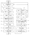
- FIG. 6 is a flowchart of initial learning of the refrigerating and air-conditioning apparatus 1 according to Embodiment 1 of the present invention.
- the reference refrigerant amount MrSTD is a reference amount that serves as a reference for determining whether or not there is refrigerant leakage when refrigerant leakage detection is performed. Since the refrigerant easily leaks as time elapses, it is necessary to calculate the reference refrigerant amount MrSTD as soon as possible after installing the refrigeration air conditioner 1. Here, it is assumed that the cooling operation is performed.
- the refrigerating and air-conditioning apparatus 1 is performing a cooling operation, and confirms whether the current operation state satisfies the initial learning start condition.
- the initial learning start condition is a condition for determining whether or not the current operation state is in a state where the total refrigerant amount can be accurately calculated. For example, the following condition is set. That is, the refrigerant amount in the accumulator 24 is calculated using the saturated gas density, assuming that all the refrigerant in the accumulator 24 is gas.
- the refrigerant amount is calculated as a gas refrigerant even though the liquid refrigerant is accumulated, and the accurate refrigerant amount is calculated. I can't. Therefore, the value calculated as the refrigerant amount of the accumulator 24 is smaller than the actual amount by the excess liquid refrigerant amount, and this miscalculation affects and the reference refrigerant amount MrSTD in step S34 described later cannot be accurately calculated. Therefore, initial learning is not performed when the surplus liquid refrigerant is accumulated in the accumulator 24 as described above. That is, as the initial learning start condition, it is specified that the refrigerant is not accumulated in the accumulator 24.
- Whether or not the refrigerant has accumulated in the accumulator 24 is determined based on the current operation data based on the degree of superheat SH (the degree of superheat at the inlet of the compressor 21) of the refrigerant at the outlets of the indoor heat exchangers 42A and 42B. Judgment can be made based on whether it is 0 or more. That is, when the superheat degree SH is 0 or more, it is determined that the refrigerant is not accumulated in the accumulator 24, and when the superheat degree SH is less than 0, the refrigerant is accumulated in the accumulator 24. to decide.
- step S22 it is determined whether or not the initial learning start condition is satisfied, and when the driving state satisfies the initial learning condition, the process proceeds to step S22.
- step S22 it is confirmed whether or not the amount of refrigerant charged in the initial stage when the refrigeration air conditioner 1 is installed is known (already input). For example, when the refrigeration air conditioner 1 is newly installed or when the initial filling amount is recorded in the storage unit 3c, the process proceeds to step S23. Further, when the initial filling amount is not known, for example, when there is no record of the initial filling amount in the existing refrigeration air conditioner 1, the process proceeds to step S28. If the initial charging amount is known, the value is used as a reference refrigerant amount MrSTD for determining whether or not refrigerant leaks, and is used for determining whether or not refrigerant leaks.
- Steps S23 to S27 describe the flow when the initial filling amount is known.
- step S23 it is determined whether or not the current operation state matches a preset operation data acquisition condition. While the current operation state does not match the operation data acquisition condition, the process returns to step S21, and the determinations of steps S21, S22, and S28 are repeated until the operation state that matches the operation data acquisition condition is reached.
- the present embodiment is characterized in that the internal volume of the refrigerant extension pipe (the liquid refrigerant extension pipe 6 and the gas refrigerant extension pipe 7) can be calculated from the operation data acquired during the normal operation without using a special operation mode.
- the operation data used when calculating the internal volume of the refrigerant extension pipe the operation data in an operation state that satisfies a predetermined operation data acquisition condition is used.
- the operation data acquisition condition when the initial filling amount is known may be the same as the initial learning start condition in step S21 or another condition may be specified, but in any case, the internal volume of the refrigerant extension pipe
- the operation state that can accurately calculate is specified.
- step S24 when the current operation state is an operation state that satisfies the operation data acquisition condition, the operation data at that time is automatically acquired and held as operation data for initial learning.
- step S25 since the internal volume VPL of the liquid refrigerant extension pipe 6 is unknown, a calculation formula for the total refrigerant amount Mr is determined with the internal volume VPL being an unknown number. At this time, the internal volume VPG of the gas refrigerant extension pipe 7 is calculated using the liquid refrigerant extension pipe internal volume VPL from the following equation (1).
- VPG ⁇ ⁇ VPL (1)
- the gas refrigerant density of the gas refrigerant extension pipe 7 is a few tens of times smaller than the liquid refrigerant density of the liquid refrigerant extension pipe 6, and the internal volume VPG of the gas refrigerant extension pipe 7 calculates the total refrigerant amount Mr.
- the influence given to this is smaller than the internal volume VPL of the liquid refrigerant extension pipe 6.
- the internal volume VPG of the gas refrigerant extension pipe 7 is simply calculated from the product VPL using the following equation (1).
- the volume ratio ⁇ is stored in advance in the storage unit 3c of the control unit 3.
- step S25 and step S26 the calculation formula for the total refrigerant amount Mr is determined using the operation data for initial learning acquired in step S24 while the internal volume VPL of the liquid refrigerant extension pipe 6 is kept unknown. Then, the internal volume VPL of the liquid refrigerant extension pipe 6 is calculated using the fact that the total refrigerant amount Mr obtained by this calculation formula is equal to the initial filling amount MrSTD. The calculation of the total refrigerant amount Mr is the same as the calculation method of the total refrigerant amount in step S6 described above.
- VPL (MrSTD ⁇ MA) / ( ⁇ L + ⁇ ⁇ ⁇ G)
- ⁇ L refrigerant density of the liquid refrigerant extension pipe 6
- ⁇ G refrigerant density of the gas refrigerant extension pipe 7
- MA refrigerant extension of the refrigerant circuit 10 Refrigerant amount in parts other than piping
- step S26 the internal volume VPG of the gas refrigerant extension pipe 7 is determined from the internal volume VPL of the liquid refrigerant extension pipe 6 obtained in step S25 and the above equation (1).
- the internal volume of the refrigerant extension pipe can be calculated in one operation.
- step S28 it is determined whether or not the current operation state matches a preset operation data acquisition condition.
- the operation data acquisition condition here specifies an operation state that satisfies at least the initial learning start condition.
- the initial filling amount is known, it is possible to calculate the refrigerant extension pipe internal volume with one operation data.
- the initial filling amount is unknown, a plurality of (two or more) operations are performed.
- the refrigerant extension pipe internal volume cannot be calculated without acquiring data. Therefore, operation data acquisition conditions are set in accordance with the number of operation data acquisitions. Below, it demonstrates as what acquires two driving
- the operation data acquisition condition it is preferable to designate a state in which the difference in the operation state is large, in particular, a state in which the difference in the refrigerant density of the liquid refrigerant extension pipe 6 is large.
- a state in which the difference in the refrigerant density of the liquid refrigerant extension pipe 6 is large The case where it is ° C, the case where the refrigerant temperature of liquid refrigerant extension piping 6 is 10 ° C, etc. correspond. This is because, on the contrary, if the operation states are similar, the difference between the values of the operation data is small, so that the calculation of the internal volume of the refrigerant extension pipe is greatly affected by an error.
- the case in which the difference in the operation state occurs specifically includes, for example, the indoor units 4A and 4B. This corresponds to the case where one indoor unit 4A is stopped from the state where both of the two are operated.
- step S28 it is checked whether or not the current operation state matches the operation data acquisition condition.
- it is checked from the outlet temperature of the subcooler 26 obtained by the liquid pipe temperature sensor 33d whether the refrigerant temperature of the liquid refrigerant extension pipe 6 is 20 ° C. or 10 ° C.
- step S29 when the refrigerant temperature of the liquid refrigerant extension pipe 6 matches either 20 ° C. or 10 ° C., the control unit 3 automatically acquires the operation data at that time as operation data for initial learning. Hold.
- step S30 it is determined whether or not two pieces of operation data that match each operation data acquisition condition have been acquired. If two operation data that match each operation data acquisition condition have not been acquired, the process returns to step S21, and the determinations of steps S21, S22, and S28 are repeated until two operation data that match each operation data acquisition condition are acquired. On the other hand, when two driving data that match each driving data acquisition condition are acquired, the process proceeds to the next step S31.
- step S31 a calculation formula for the total refrigerant amount Mr is determined for each of the two operation data acquired in step S29.
- a calculation formula for the total refrigerant amount Mr is determined for each operation data while being unknown.
- ⁇ L1 refrigerant density of the liquid refrigerant extension pipe 6 obtained from the operation data
- ⁇ G1 refrigerant density of the gas refrigerant extension pipe 7 obtained from the operation data
- MA1 other than the refrigerant extension pipe of the refrigerant circuit 10 obtained from the operation data 1
- ⁇ L2 the refrigerant density of the liquid refrigerant extension pipe 6 obtained from the operation data 2
- ⁇ G2 the refrigerant density of the gas refrigerant extension pipe 7 obtained from the operation data 2
- MA2 the refrigerant circuit 10 obtained from the operation data 2 Of refrigerant other than the refrigerant extension pipe
- ⁇ Volume ratio of the liquid refrigerant extension pipe 6 and the gas refrigerant extension pipe 7 Of these calculation formulas for Mr
- step S32 since the amount of refrigerant originally filled is equal, the following equation is created using the fact that Mr1 and Mr2 are equal, and the internal volume VPL of the liquid refrigerant extension pipe 6 is calculated by solving the equation.
- the liquid refrigerant extension pipe internal volume VPL can be calculated from at least two operation data.
- step S33 the internal volume VPG of the gas refrigerant extension pipe 7 is calculated from the internal volume VPL of the liquid refrigerant extension pipe 6 obtained in step S32 and the above equation (1).
- step S34 the total refrigerant amount Mr1 is calculated by substituting the internal volume VPL of the liquid refrigerant extension pipe 6 calculated in steps S32 and S33 into the calculation formula for Mr1, and this total refrigerant amount Mr1 is used as the reference refrigerant. The amount is MrSTD.
- step S35 an initial learned record is recorded in the storage unit 3c.
- step S36 the internal volume VPL of the liquid refrigerant extension pipe 6 calculated by the above processing, the internal volume VPG of the gas refrigerant extension pipe 7, and the reference refrigerant amount (initial charge amount when the initial charge amount is known). MrSTD is stored in the storage unit 3c, and the initial learning is terminated.
- the operation data at that time is automatically acquired, and the internal volume of the refrigerant extension pipe is calculated using the operation data. calculate. Therefore, the internal volume of the refrigerant extension pipe can be calculated using the operation data during the normal operation without performing a specific operation for calculating the internal volume of the refrigerant extension pipe. Moreover, since the calculation of the internal volume of the refrigerant extension pipe and the detection of the refrigerant leakage are automatically performed simply by starting the normal operation, the trouble of performing the specific operation as in the prior art is not required.
- the internal volume of the refrigerant extension pipe and the refrigerant extension are based on the operation data during normal operation.
- the amount of refrigerant in the pipe can be easily calculated. Therefore, in calculating the internal volume of the refrigerant extension pipe and determining whether or not there is a refrigerant leak, it is possible to reduce as much as possible the trouble of inputting information on the refrigerant extension pipe.
- the initial learning start condition and the operation data acquisition condition are satisfied, that is, in the operation state in which the excess liquid refrigerant is not accumulated in the accumulator 24.
- the internal volume of the refrigerant extension pipe is calculated based on the operation data. For this reason, it is possible to accurately calculate the internal volume of the refrigerant extension pipe and the reference refrigerant amount. Therefore, the amount of refrigerant in the refrigerant extension pipe can be calculated with high accuracy, and in turn, calculation of the total amount of refrigerant in the refrigeration air conditioner and detection of refrigerant leakage can be performed with high accuracy. As a result, it is possible to quickly detect refrigerant leakage, and it is possible to prevent damage to the refrigeration air conditioner itself as well as the natural environment.
- a plurality of states in which the refrigerant density of the liquid refrigerant extension pipe 6 is different are specified as the operation data acquisition condition. More preferably, a plurality of states in which the difference in the refrigerant density of the liquid refrigerant extension pipe 6 is large are designated.
- the gas refrigerant extension pipe 7 is obtained by a function of the internal volume VPL of the liquid refrigerant extension pipe 6. Therefore, the acquisition necessary for calculating the gas refrigerant extension pipe 7 is required. The number of operations can be reduced. Therefore, for example, when the initial filling amount is known, the operation data is acquired once, and the internal volumes VPL and VPG of the refrigerant extension pipe can be calculated.
- the internal volume of the refrigerant extension pipe is calculated from one operation data, but the present invention is not limited to this.
- the number of acquired operation data may be increased, the refrigerant extension pipe internal volume may be calculated for each operation data, and the average value of the calculated values may be used as the refrigerant extension pipe internal volume.
- the reliability of the calculation result of the refrigerant extension pipe internal volume that is, the reliability of the refrigerant leakage detection result.
- the refrigerant extension pipe internal volume is once calculated using each operation data, and the average value is calculated using only data having a large value as a result of the calculation.
- the value of the calculation result is large or small, for example, check the calculation result of the refrigerant extension pipe internal volume in chronological order, and if the value falls by a predetermined value or more than the previous calculation result, calculate after that Judge that the result is small.
- the present invention is not limited to this and may be performed during the heating operation.
- liquid refrigerant is stored in a refrigerant tank such as the accumulator 24, and an error occurs when calculating the internal volume of the refrigerant extension pipe. Easy to come out. For this reason, in order to make the calculation formula of the total refrigerant quantity Mr in steps S25 and S31 of FIG. 6 accurate and to accurately calculate the finally obtained refrigerant extension pipe internal volume, the initial learning start condition is described above.
- the refrigerant superheat degree SH (superheat degree at the inlet of the compressor 21) at the outlets of the indoor heat exchangers 42A and 42B is set to 0 or more, and the following operation state is designated. May be. That is, for example, when the compressor operating capacity is a predetermined value or more (for example, 50% or more), or when the outside air temperature is a predetermined temperature or more (for example, 0 ° C. or more), the compressor operating capacity is further set to a predetermined value by combining both. This is the case when the outside air temperature is equal to or higher than the predetermined temperature.
- the refrigerant leakage detection after the initial learning may be performed not only during the cooling operation but also during the heating operation as in the case of the initial learning.
- the refrigerant tank such as the accumulator 24 is used. It is necessary to perform the operation when the liquid refrigerant is not accumulated in the operation state. That is, when the liquid refrigerant is accumulated in the accumulator 24, as described above, the value calculated as the refrigerant amount of the accumulator 24 is smaller than the actual amount by the excess liquid refrigerant amount, and this miscalculation has an effect. There is a possibility of erroneous detection that there is a refrigerant leak. Therefore, the refrigerant leakage detection is not performed when the excess liquid refrigerant is accumulated in the accumulator 24. Thereby, refrigerant
- the operation data may be measured by operating each of the cooling and heating, and the volume of the refrigerant extension pipe may be calculated using the operation data.
- the initial learning allows the refrigerant extension pipe internal volume to be calculated from the normal operation data while reducing the effort of inputting information such as the length of the refrigerant extension pipe as much as possible. And it is always possible to perform remote monitoring by transmitting refrigerant leakage presence / absence data from the output unit 3h to a management center or the like via a communication line. Therefore, it is possible to cope with sudden refrigerant leakage immediately before an abnormality such as damage to the equipment or a decrease in capability occurs, and it is possible to suppress the progression of refrigerant leakage as much as possible.
- the reliability of the refrigerating and air-conditioning apparatus 1 can be improved, the environmental condition can be prevented from deteriorating as much as possible due to the outflow of refrigerant, and further, the inconvenience of excessive operation with a small amount of refrigerant due to refrigerant leakage can be prevented.
- the life of the air conditioner 1 can be extended.
- the accurate refrigerant extension pipe internal volume can be calculated by adding the known pipe inner diameters to the refrigerant extension pipe length. it can.
- coolant amount in the refrigerating air conditioner 1 can be correctly calculated by each integrating
- Embodiment 2 the gas refrigerant extension pipe internal volume VPG is simply calculated as a function of the liquid refrigerant extension pipe internal volume VPL.
- the respective internal volumes of the gas refrigerant extension pipe 7 and the liquid refrigerant extension pipe 6 are calculated independently. In this case, at least three pieces of operation data are required for calculating each internal volume.
- the initial learning process in the control unit 3 is different from the refrigeration air conditioner 1 in the first embodiment, and the refrigerant circuit and control block configuration of the other refrigeration air conditioners 1 are the same as those in the first embodiment. It is the same. Further, the flow of the refrigerant leakage detection process other than the initial learning is the same as that in the first embodiment.
- the initial learning process in the refrigeration air-conditioning apparatus 1 according to the second embodiment will be described.
- an outline of the initial learning according to the second embodiment will be described.
- the gas refrigerant extension pipe internal volume VPG is used as a function of the liquid refrigerant extension pipe internal volume VPL. Therefore, the unknown is only the liquid refrigerant extension pipe internal volume VPL.
- both the liquid refrigerant extension pipe internal volume VPL and the gas refrigerant extension pipe internal volume VPG are unknown. Two formulas are needed to reveal the two unknowns.
- At least three operation data acquisition conditions are set, operation data in an operation state that matches each operation data acquisition condition is acquired, and the total refrigerant amount Mr1, Mr2 in the refrigerant circuit 10 is obtained for each of the three operation data.
- the calculation formula of Mr3 is determined. Since the amount of refrigerant originally filled is equal, two equations are created using the fact that all the refrigerant amounts Mr1, Mr2, Mr3 are all equal, and two unknowns (liquid refrigerant extension pipe internal volume VPL and gas refrigerant) The extension pipe internal volume VPG) is clarified.
- FIG. 7 is a flowchart of initial learning of the refrigerating and air-conditioning apparatus 1 according to Embodiment 2 of the present invention.
- step S41 it is confirmed whether or not an initial learning condition is satisfied.
- step S41 is the same as step S21 of FIG. 6 of the first embodiment, and it is determined whether or not excess liquid refrigerant is accumulated in the accumulator 24. If it is determined that the excess liquid refrigerant is not accumulated in the accumulator 24, the process proceeds to the next step S42.
- step S42 it is determined whether or not the current operation state matches a preset operation data acquisition condition.
- at least three operation data acquisition conditions are set, and in step S43, the control unit 3 operates at that time every time the current operation state matches any of the three operation data acquisition conditions.
- the three operating data acquisition conditions include, for example, the case where the refrigerant temperature of the liquid refrigerant extension pipe 6 is 30 ° C., the case where the refrigerant temperature of the liquid refrigerant extension pipe 6 is 20 ° C., and the liquid refrigerant extension pipe 6. This corresponds to the case where the refrigerant temperature is 10 ° C.
- step S44 it is determined whether or not three pieces of data that match each operation data acquisition condition have been acquired. If three data that match each operation data acquisition condition have not been acquired, the process returns to step S42, and the determination in step S42 is continued until three data that match each operation data acquisition condition are acquired. On the other hand, when three driving data that match each driving data acquisition condition are acquired, the process proceeds to the next step S45.
- step S45 a calculation formula for the total refrigerant amount Mr is determined for each of the three operation data stored in step S43.
- the calculation formula of the total refrigerant quantity Mr is determined for each operation data with the unknown.
- the total refrigerant amount Mr obtained from the first operation data 1 is Mr1
- the total refrigerant amount Mr obtained from the first operation data 2 is Mr2
- the total refrigerant amount Mr obtained from the third operation data 3 is Mr3. Then, the following calculation formulas are obtained.
- ⁇ G1 refrigerant density of the gas refrigerant extension pipe 7 obtained from the operation data 1
- MA1 other than the refrigerant extension pipe of the refrigerant circuit 10 obtained from the operation data 1
- ⁇ L2 refrigerant density of the liquid refrigerant extension pipe 6 obtained from the operation data 2
- ⁇ G2 refrigerant density of the gas refrigerant extension pipe 7 obtained from the operation data 2
- MA2 refrigerant circuit 10 obtained from the operation data 2
- ⁇ L3 refrigerant density of liquid refrigerant extension pipe 6 obtained from operation data 3
- ⁇ G3 refrigerant density
- step S46 since the amount of refrigerant originally filled is equal, the following two equations are created using the fact that Mr1, Mr2, and Mr3 are all equal, and the simultaneous equation is solved, thereby extending the liquid refrigerant extension pipe.
- both the liquid refrigerant extension pipe internal volume VPL and the gas refrigerant extension pipe internal volume VPG can be calculated from the operation data of at least three times.
- step S47 the total refrigerant quantity Mr1 is calculated by substituting the liquid refrigerant extension pipe internal volume VPL and the gas refrigerant extension pipe internal volume VPG calculated in step S46 into the calculation formula of Mr1, and this total refrigerant quantity Mr1. Is the reference refrigerant amount MrSTD.
- the internal volume VPL of the liquid refrigerant extension pipe 6, the internal volume VPG of the gas refrigerant extension pipe 7, and the reference refrigerant amount MrSTD are determined.
- step S48 an initial learned record is recorded in the storage unit 3c.
- step S49 the internal volume VPL of the liquid refrigerant extension pipe 6 calculated by the above processing, the internal volume VPG of the gas refrigerant extension pipe 7, and the reference refrigerant amount (initial charge amount if the initial charge amount is known). MrSTD is stored in the storage unit 3c, and the initial learning is terminated.
- the same effects as those of the first embodiment can be obtained, and the internal volumes of the gas refrigerant extension pipe 7 and the liquid refrigerant extension pipe 6 can be calculated respectively.
- Refrigeration air conditioner 2 outdoor unit, 3 control unit, 3a measurement unit, 3b calculation unit, 3c storage unit, 3d determination unit, 3e drive unit, 3f display unit, 3g input unit, 3h output unit, 4A, 4B indoor unit (Usage unit), 6 liquid refrigerant extension pipe, 6A liquid main pipe, 6a liquid branch pipe, 7 gas refrigerant extension pipe, 7A gas main pipe, 7a gas branch pipe, 10 refrigerant circuit, 10a indoor refrigerant circuit, 10b indoor refrigerant circuit 10c outdoor refrigerant circuit, 10z main refrigerant circuit, 21 compressor, 22 four-way valve, 23 outdoor heat exchanger, 24 accumulator, 26 subcooler, 27 outdoor fan, 28 liquid side closing valve, 29 gas side closing valve , 31 outdoor control unit, 32a indoor control unit, 33a suction temperature sensor, 33b discharge temperature sensor, 33c outdoor temperature Sensor, 33d liquid pipe temperature sensor, 33e liquid side temperature sensor, 33f gas side temperature sensor, 33g indoor temperature sensor, 33h liquid side
Landscapes
- Engineering & Computer Science (AREA)
- Physics & Mathematics (AREA)
- Mechanical Engineering (AREA)
- Thermal Sciences (AREA)
- General Engineering & Computer Science (AREA)
- Air Conditioning Control Device (AREA)
Abstract
通常運転中において計測された運転データが示す運転状態が運転データ取得条件を満たす状態となると、そのときの運転データを初期学習用の運転データとして取得し、取得した初期学習用の運転データに基づいて冷媒延長配管の内容積を算出する。そして、算出した冷媒延長配管の内容積と現在の運転データとに基づいて冷媒回路10内の全冷媒量を算出し、算出した全冷媒量と基準冷媒量とを比較して冷媒漏洩の有無を判定する。
Description
本発明は、熱源である室外ユニットと利用側である室内ユニットとが冷媒延長配管を介して接続されることによって構成される冷凍空調装置において、冷媒回路内の冷媒量を計算する機能の高精度化に関する。
従来より、熱源機である室外ユニットと利用側である室内ユニットとが冷媒延長配管を介して接続されることによって構成されるセパレート型の冷凍空調装置において、延長配管内容積判定運転(冷房運転で冷媒延長配管内の密度が異なる2つの運転)を行い、2つの運転状態間の冷媒延長配管以外の冷媒増減量を演算し、冷媒の増減量を冷媒延長配管内の冷媒の密度変化量で除算することにより冷媒延長配管の内容積を算出し、冷媒延長配管の内容積を用いて冷媒延長配管内の冷媒量を算出するようにした技術がある(例えば、特許文献1参照)。
しかし、上述の冷媒延長配管の内容積推測方法では、冷凍空調装置設置時の延長配管内容積の算出の際に延長配管内容積判定運転という特殊な運転を行うため、手間がかかる他、既設の冷凍空調装置に対して延長配管内容積判定運転を行うことは困難である。
本発明はこのような点に鑑みなされたもので、通常運転時に得られる運転データを用いて冷媒延長配管の内容積を正確に算出でき、冷媒回路内の全冷媒量の算出および冷媒漏洩検知を高精度に行うことが可能な冷凍空調装置を得ることを目的とする。
本発明に係る冷凍空調装置は、熱源ユニットである室外ユニットと利用側ユニットである室内ユニットとが冷媒延長配管で接続される冷媒回路と、冷媒回路の主要部の温度と圧力とを運転データとして計測する計測部と、運転状態を指定する運転データ取得条件を有し、通常運転中において計測部により計測された運転データが示す運転状態が運転データ取得条件を満たす状態となると、そのときの運転データを初期学習用の運転データとして取得し、取得した初期学習用の運転データと冷凍空調装置の設置初期の冷媒充填量である初期充填量とに基づいて冷媒延長配管の内容積を算出するとともに、算出した冷媒延長配管の内容積と初期学習用の運転データとに基づいて冷媒回路からの冷媒漏洩の判断の基準となる基準冷媒量を算出する演算部と、演算部によって算出された冷媒延長配管の内容積と通常運転中に計測部により計測された運転データとに基づいて冷媒回路内の全冷媒量を算出し、算出した全冷媒量と基準冷媒量とを比較して冷媒漏洩の有無を判定する判定部とを備えたものである。
本発明によれば、冷凍空調装置を新設する場合に限らず、既設の冷凍空調装置に対しても、特別な運転を行うことなく通常運転時の運転データにより冷媒延長配管の内容積を算出できる。また、運転データ取得条件を満たす運転状態のときの運転データを用いて冷媒延長配管の内容積の算出を行うため、冷媒延長配管の内容積の算出を高精度に行うことができ、引いては冷凍空調装置内の全冷媒量の算出および冷媒漏洩検知を精度良く行うことができる。
実施の形態1.
以下、図面に基づいて、本発明にかかる冷凍空調装置の実施形態について説明する。
以下、図面に基づいて、本発明にかかる冷凍空調装置の実施形態について説明する。
<機器の構成>
図1は、本発明の実施の形態1に係る冷凍空調装置1の構成図である。冷凍空調装置1は、蒸気圧縮式の冷凍サイクル運転を行うことによって、ビル等の室内の冷暖房に使用される装置である。冷凍空調装置1は、主として、熱源ユニットとしての室外ユニット2と、それに並列に接続された複数台(本実施形態では、2台)の利用ユニットとしての室内ユニット4A、4B、液冷媒延長配管6と、ガス冷媒延長配管7とを備えている。液冷媒延長配管6は、室外ユニット2と室内ユニット4A、4Bとを接続して液冷媒が通過する配管であり、液主管6Aと、液枝管6a、6bと、分配器51aとが接続されて構成されている。また、ガス冷媒延長配管7は、室外ユニット2と室内ユニット4A、4Bとを接続してガス冷媒が通過する配管であり、ガス主管7Aと、ガス枝管7a、7bと、分配器52aとが接続されて構成されている。
図1は、本発明の実施の形態1に係る冷凍空調装置1の構成図である。冷凍空調装置1は、蒸気圧縮式の冷凍サイクル運転を行うことによって、ビル等の室内の冷暖房に使用される装置である。冷凍空調装置1は、主として、熱源ユニットとしての室外ユニット2と、それに並列に接続された複数台(本実施形態では、2台)の利用ユニットとしての室内ユニット4A、4B、液冷媒延長配管6と、ガス冷媒延長配管7とを備えている。液冷媒延長配管6は、室外ユニット2と室内ユニット4A、4Bとを接続して液冷媒が通過する配管であり、液主管6Aと、液枝管6a、6bと、分配器51aとが接続されて構成されている。また、ガス冷媒延長配管7は、室外ユニット2と室内ユニット4A、4Bとを接続してガス冷媒が通過する配管であり、ガス主管7Aと、ガス枝管7a、7bと、分配器52aとが接続されて構成されている。
(室内ユニット)
室内ユニット4A、4Bは、ビル等の室内の天井に埋め込みや吊り下げ等により、又は、室内の壁面に壁掛け等により設置されている。室内ユニット4A、4Bは、液冷媒延長配管6とガス冷媒延長配管7とを用いて室外ユニット2に接続されており、冷媒回路10の一部を構成している。
室内ユニット4A、4Bは、ビル等の室内の天井に埋め込みや吊り下げ等により、又は、室内の壁面に壁掛け等により設置されている。室内ユニット4A、4Bは、液冷媒延長配管6とガス冷媒延長配管7とを用いて室外ユニット2に接続されており、冷媒回路10の一部を構成している。
次に、室内ユニット4A、4Bの構成について説明する。尚、室内ユニット4A、4Bは同様の構成であるため、ここでは、室内ユニット4Aの構成のみ説明する。室内ユニット4Bの構成は、室内ユニット4Aの各部を示すAの符号の代わりにBの符号を付した構成に相当する。
室内ユニット4Aは、主として、冷媒回路10の一部を構成する室内側冷媒回路10a(室内ユニット4Bでは、室内側冷媒回路10b)を有している。この室内側冷媒回路10aは、主として、膨張機構としての膨張弁41Aと、利用側熱交換器としての室内熱交換器42Aとを有している。
本実施形態において、膨張弁41Aは、室内側冷媒回路10a内を流れる冷媒の流量の調節等を行うために、室内熱交換器42Aの液側に接続された電動膨張弁である。
本実施形態において、室内熱交換器42Aは、伝熱管と多数のフィンとにより構成されたクロスフィン式のフィン・アンド・チューブ型熱交換器であり、冷房運転時には冷媒の蒸発器として機能して室内空気を冷却し、暖房運転時には冷媒の凝縮器として機能して室内空気を加熱する熱交換器である。
本実施形態において、室内ユニット4Aは、ユニット内に室内空気を吸入して室内熱交換器42Aにおいて冷媒と熱交換させた後に、供給空気として室内に供給するための送風ファンとしての室内ファン43Aを有している。室内ファン43Aは、室内熱交換器42Aに供給する空気の風量を可変することが可能なファンであり、本実施形態において室内ファン43Aは、DCファンモーターによって駆動される遠心ファンや多翼ファン等である。
また、室内ユニット4Aには、各種のセンサーが設けられている。室内熱交換器42A、42Bのガス側には、冷媒の温度(すなわち、暖房運転時における凝縮温度Tc又は冷房運転時における蒸発温度Teに対応する冷媒温度)を検出するガス側温度センサー33f、33iが設けられている。室内熱交換器42A、42Bの液側には、冷媒の温度Teoを検出する液側温度センサー33e、33hが設けられている。室内ユニット4A、4Bの室内空気の吸入口側には、ユニット内に流入する室内空気の温度(すなわち、室内温度Tr)を検出する室内温度センサー33g、33jが設けられている。本実施形態において、前記33e、33f、33g、33h、33i、33jの各温度センサーは、サーミスタからなる。
また、室内ユニット4A、4Bは、室内ユニット4A、4Bを構成する各部の動作を制御する室内側制御部32a、32bを有している。そして、室内側制御部32a、32bは、室内ユニット4A、4Bの制御を行うために設けられたマイクロコンピュータやメモリ等を有している。室内側制御部32a、32bは、室内ユニット4A、4Bを個別に操作するためのリモコン(図示せず)との間で制御信号等のやりとりを行ったり、室外ユニット2との間で伝送線を介して制御信号等のやりとりを行ったりすることができるようになっている。
(室外ユニット)
室外ユニット2は、ビル等の室外に設置されており、液主管6A、液枝管6a、6bおよびガス主管7A、ガス枝管7a、7bで室内ユニット4A、4Bに接続されており、室内ユニット4A、4Bとの間で冷媒回路10を構成している。
室外ユニット2は、ビル等の室外に設置されており、液主管6A、液枝管6a、6bおよびガス主管7A、ガス枝管7a、7bで室内ユニット4A、4Bに接続されており、室内ユニット4A、4Bとの間で冷媒回路10を構成している。
次に、室外ユニット2の構成について説明する。室外ユニット2は、主として、冷媒回路10の一部を構成する室外側冷媒回路10cを有している。この室外側冷媒回路10cは、主として、圧縮機21と、四方弁22と、室外熱交換器23と、アキュムレーター24と、過冷却器26と、液側閉鎖弁28と、ガス側閉鎖弁29とを有している。
圧縮機21は、運転容量を可変することが可能な圧縮機であり、本実施形態において、インバータにより周波数Fが制御されるモーターによって駆動される容積式圧縮機である。本実施形態において、圧縮機21は1台のみであるが、これに限定されず、室内ユニットの接続台数等に応じて、2台以上の圧縮機が並列に接続されていてもよい。
四方弁22は、冷媒の流れの方向を切り換えるための弁である。四方弁22は、冷房運転時には、実線で示されるように切り替えられ、圧縮機21の吐出側と室外熱交換器23のガス側とを接続するとともにアキュムレーター24とガス主管7A側とを接続する。これにより、室外熱交換器23は圧縮機21によって圧縮される冷媒の凝縮器として機能し、また、室内熱交換器42A、42Bは蒸発器として機能する。四方弁22は、暖房運転時には、四方弁の点線で示されるように切り替えられ、圧縮機21の吐出側とガス主管7Aとを接続するとともにアキュムレーター24と室外熱交換器23のガス側とを接続する。これにより、室内熱交換器42A、42Bは圧縮機21によって圧縮される冷媒の凝縮器として機能し、また、室外熱交換器23は蒸発器として機能する。
本実施形態において、室外熱交換器23は、伝熱管と多数のフィンとにより構成されたクロスフィン式のフィン・アンド・チューブ型熱交換器である。室外熱交換器23は、上述したように冷房運転時には冷媒の凝縮器として機能し、暖房運転時には冷媒の蒸発器として機能する。室外熱交換器23は、そのガス側が四方弁22に接続され、液側が液主管6Aに接続されている。
本実施形態において、室外ユニット2は、ユニット内に室外空気を吸入して、室外熱交換器23において冷媒と熱交換させた後に、室外に排出するための送風ファンとしての室外ファン27を有している。この室外ファン27は、室外熱交換器23に供給する空気の風量を可変することが可能なファンであり、本実施形態において、DCファンモーターからなるモーターによって駆動されるプロペラファン等である。
アキュムレーター24は、四方弁22と圧縮機21との間に接続されており、室内ユニット4A、4Bの運転負荷の変動等に応じて冷媒回路10内に発生する余剰冷媒を溜めることが可能な容器である。
過冷却器26は、2重管式の熱交換器であり、室外熱交換器23において凝縮された後に、膨張弁41A、41Bに送られる冷媒を冷却するために設けられている。過冷却器26は、本実施形態において、室外熱交換器23と液側閉鎖弁28との間に接続されている。
本実施形態において、過冷却器26の冷却源としてのバイパス回路71が設けられている。尚、以下の説明では、冷媒回路10からバイパス回路71を除いた部分を、主冷媒回路10zと呼ぶことにする。
バイパス回路71は、室外熱交換器23から膨張弁41A、41Bへ送られる冷媒の一部を主冷媒回路10zから分岐させて圧縮機21の吸入側に戻すように主冷媒回路10zに接続されている。具体的には、バイパス回路71は、室外熱交換器23から膨張弁41A、41Bに送られる冷媒の一部を過冷却器26と液側閉鎖弁28の間の位置から分岐させ、電動膨張弁からなるバイパス流量調整弁72と過冷却器26とを介して圧縮機21の吸入側に戻すように接続されている。これにより、室外熱交換器23から室内膨張弁41A、41Bに送られる冷媒は、過冷却器26において、バイパス流量調整弁72によって減圧された後にバイパス回路71を流れる冷媒によって冷却される。すなわち、過冷却器26は、バイパス流量調整弁72の開度調節によって能力制御が行われる。
液側閉鎖弁28およびガス側閉鎖弁29は、外部の機器・配管(具体的には、液主管6Aおよびガス主管7A)との接続口に設けられた弁である。
また、室外ユニット2には、複数の圧力センサーと温度センサーが設けられている。圧力センサーとしては、圧縮機21の吸入圧力Psを検出する吸入圧力センサー34aと、圧縮機21の吐出圧力Pdを検出する吐出圧力センサー34bとが設置されている。
温度センサーはサーミスターからなり、温度センサーとしては、吸入温度センサー33aと、吐出温度センサー33bと、熱交温度センサー33kと、液側温度センサー33lと、液管温度センサー33dと、バイパス温度センサー33zと、室外温度センサー33cとが設置されている。
吸入温度センサー33aは、アキュムレーター24と圧縮機21との間の位置に設けられ圧縮機21の吸入温度Tsを検出する。吐出温度センサー33bは、圧縮機21の吐出温度Tdを検出する。熱交温度センサー33kは、室外熱交換器23内を流れる冷媒の温度を検出する。液側温度センサー33lは、室外熱交換器23の液側に設置され、室外熱交換器23の液側の冷媒温度を検出する。液管温度センサー33dは、過冷却器26の主冷媒回路10z側の出口に設置され冷媒の温度を検出する。バイパス温度センサー33zは、バイパス回路71の過冷却器26出口を流れる冷媒の温度を検出する。室外温度センサー33cは、室外ユニット2の室外空気の吸入口側に設置されユニット内に流入する室外空気の温度を検出する。
また、室外ユニット2は、室外ユニット2を構成する各要素の動作を制御する室外側制御部31を有している。そして、室外側制御部31は、室外ユニット2の制御を行うために設けられたマイクロコンピュータと、メモリと、モーターを制御するインバータ回路等とを有している。そして、室外側制御部31は、室内ユニット4A、4Bの室内側制御部32a、32bとの間で伝送線を介して制御信号等のやりとりを行うように構成されている。室外側制御部31は、室内側制御部32a、32bと共に冷凍空調装置1全体の運転制御を行う制御部3を構成している。
図2は、本発明の実施の形態1に係る冷凍空調装置1の制御ブロック図である。制御部3は、圧力センサー34a、34b、温度センサー33a~33l、33zの検出信号を受けることができるように接続される。また、制御部3はこれらの検出信号等に基づいて各種機器(圧縮機21、ファン27、ファン43A、43B)および弁(四方弁22、流量調整弁(液側閉鎖弁28、ガス側閉鎖弁29、バイパス流量調整弁72)、膨張弁41A、41B)を制御することができるように各種機器および弁に接続されている。
また、制御部3は、測定部3a、演算部3b、記憶部3c、判定部3d、駆動部3e、表示部3f、入力部3gおよび出力部3hを備えている。測定部3aは圧力センサー34a、34bおよび温度センサー33a~33l、33zからの情報を測定する箇所であり、圧力センサー34a、34bおよび温度センサー33a~33l、33zと共に計測部を構成する箇所である。演算部3bは測定部3aで測定した情報等に基づいて冷媒延長配管の内容積の算出や、冷媒回路10からの冷媒漏洩判断の基準となる基準冷媒量を算出する箇所である。記憶部3cは測定部3aで測定した値や演算部3bで演算した値を記憶したり、後述の内容積データや初期充填量を記憶したり、また、外部からの情報を記憶したりする箇所である。判定部3dは記憶部3cに記憶された基準冷媒量と演算により算出された冷媒回路10の全冷媒量とを比較して冷媒漏洩の有無を判定する箇所である。
駆動部3eは冷凍空調装置1の駆動する要素である圧縮機モーター、弁、ファンモーターの制御を行う箇所である。表示部3fは冷媒充填が完了した場合や、冷媒漏洩を検知した場合等にその情報を表示して外部へ知らせたり、冷凍空調装置1を運転させる上で生じる異常を表示させたりする箇所である。入力部3gは各種制御用の設定値の入力や変更を行ったり冷媒充填量等の外部情報を入力したりする箇所である。出力部3hは測定部3aで測定した測定値や演算部3bで演算した値を外部に出力する箇所である。出力部3hは外部装置と通信するための通信部としてもよく、冷凍空調装置1は冷媒漏洩の検知結果を示す冷媒漏洩有無データを通信線等により遠方の管理センター等に送信することが可能に構成されている。
このように構成された制御部3は、四方弁22により通常運転としての冷房運転と暖房運転とを切り換えて運転を行うとともに、各室内ユニット4A、4Bの運転負荷に応じて、室外ユニット2及び室内ユニット4A、4Bの各機器の制御を行なっている。また、制御部3は、後述の冷媒漏洩検知処理を行う。
(冷媒延長配管)
冷媒延長配管は室外ユニット2と室内ユニット4A、4Bとを接続し、冷凍空調装置1内の冷媒を循環させるために必要な配管である。
冷媒延長配管は室外ユニット2と室内ユニット4A、4Bとを接続し、冷凍空調装置1内の冷媒を循環させるために必要な配管である。
冷媒延長配管は、液冷媒延長配管6(液主管6A、液枝管6a、6b)と、ガス冷媒延長配管7(ガス主管7A、ガス枝管7a、7b)とを有し、冷凍空調装置1をビル等の設置場所に設置する際に現地にて施工される冷媒配管である。室外ユニット2と室内ユニット4A、4Bとの組み合わせに応じてそれぞれ決められた管径の冷媒延長配管が使用される。
冷媒延長配管長さは現地の設置条件によって異なる。このため冷媒延長配管の内容積も設置現場によって異なったものとなり、出荷時に予め入力しておくことはできない。よって、現場ごとに冷媒延長配管の内容積を算出する必要がある。冷媒延長配管の内容積の算出方法の詳細については後述する。
本実施形態では1台の室外ユニット2と2台の室内ユニット4A、4Bの接続に分配器51a、52aと冷媒延長配管(液冷媒延長配管6およびガス冷媒延長配管7)とを用いている。液冷媒延長配管6については室外ユニット2と分配器51aの間を液主管6Aで、分配器51aと各室内ユニット4A、4Bの間を液枝管6a、6bで接続する。ガス冷媒延長配管7については室内ユニット4A、4Bと分配器52aの間をガス枝管7a、7bで、分配器52aと室外ユニット2の間をガス主管7Aで接続する。本実施形態では、分配器51a、52aはT字管を用いたがそれに限るものではなく、ヘッダを用いても構わない。また複数台の室内ユニットが接続される場合には、T字管を複数個使用して分配させてもよいし、ヘッダを用いてもよい。
以上のように、室内側冷媒回路10a、10bと、室外側冷媒回路10cと、冷媒延長配管(液冷媒延長配管6とガス冷媒延長配管7)とが接続されて冷媒回路10が構成されている。冷凍空調装置1は、冷媒回路10とバイパス回路71とを有している。そして、本実施形態の冷凍空調装置1は、室内側制御部32a、32bと室外側制御部31とから構成される制御部3によって、四方弁22により冷房運転および暖房運転を切り換えて運転を行うとともに、各室内ユニット4A、4Bの運転負荷に応じて、室外ユニット2および室内ユニット4A、4Bの各機器の制御を行なっている。
<冷凍空調装置1の動作>
次に、本実施形態の冷凍空調装置1の通常運転時の各構成要素の動作について説明する。
次に、本実施形態の冷凍空調装置1の通常運転時の各構成要素の動作について説明する。
本実施形態の冷凍空調装置1は、通常運転として冷房運転または暖房運転を行うもので、各室内ユニット4A、4Bの運転負荷に応じて室外ユニット2および室内ユニット4A、4Bの構成機器の制御を行う。以下、冷房運転、暖房運転の順に説明する。
(冷房運転)
図3は、本発明の実施の形態1に係る冷凍空調装置1の冷房運転時のp-h線図である。以下、図3および図1を用いて冷房運転について説明する。
冷房運転時は、四方弁22が図1の実線で示される状態、すなわち、圧縮機21の吐出側が室外熱交換器23のガス側に接続され、かつ、圧縮機21の吸入側がガス側閉鎖弁29およびガス冷媒延長配管7(ガス主管7A、ガス枝管7a、7b)により室内熱交換器42A、42Bのガス側に接続された状態となっている。また、液側閉鎖弁28、ガス側閉鎖弁29およびバイパス流量調整弁72は、いずれも開状態にされている。
図3は、本発明の実施の形態1に係る冷凍空調装置1の冷房運転時のp-h線図である。以下、図3および図1を用いて冷房運転について説明する。
冷房運転時は、四方弁22が図1の実線で示される状態、すなわち、圧縮機21の吐出側が室外熱交換器23のガス側に接続され、かつ、圧縮機21の吸入側がガス側閉鎖弁29およびガス冷媒延長配管7(ガス主管7A、ガス枝管7a、7b)により室内熱交換器42A、42Bのガス側に接続された状態となっている。また、液側閉鎖弁28、ガス側閉鎖弁29およびバイパス流量調整弁72は、いずれも開状態にされている。
次に、冷房運転における主冷媒回路10zの冷媒の流れについて説明を行う。
冷房運転での冷媒の流れは図1の実線矢印となる。圧縮機21により圧縮された高温高圧ガス冷媒(図3点い)は四方弁22を経て室外熱交換器23へ至り、ファン27の送風作用により凝縮液化する(図3点ろ)。このときの凝縮温度は、熱交温度センサー33kにより求められるか、または吐出圧力センサー34bの圧力を飽和温度換算することにより求められる。
室外熱交換器23で凝縮液化した冷媒は過冷却器26にてさらに過冷却度が大きくなる(図3点は)。この時の過冷却器26出口の過冷却度は、上記凝縮温度から、過冷却器26の出口側に設置された液管温度センサー33dの温度を差し引くことで求められる。
その後、冷媒は、液側閉鎖弁28を介し、液冷媒延長配管6である液主管6A、液枝管6a、6bにおいて管壁面摩擦によって圧力が降下し(図3点に)、利用ユニット4A、4Bに送られ、膨張弁41A、41Bにより減圧されて低圧の気液二相冷媒となる(図3点ほ)。気液二相冷媒は蒸発器である室内熱交換器42A、42Bにて室内ファン43A、43Bの送風作用によりガス化する(図3点へ)。
この時の蒸発温度は液側温度センサー33e、33hにて計測され、各室内熱交換器42A、42Bの出口における冷媒の過熱度SHは、ガス側温度センサー33f、33iにより検出される冷媒温度値から液側温度センサー33e、33hにより検出される冷媒温度を差し引くことによって求められる。各膨張弁41A、41Bは、室内熱交換器42A、42Bの出口(すなわち、室内熱交換器42A、42Bのガス側)における冷媒の過熱度SHが過熱度目標値SHmとなるように開度調節されている。
室内熱交換器42A、42Bを通過したガス冷媒(図3点へ)は、ガス冷媒延長配管7であるガス枝管7a、7bおよびガス主管7Aに至り、これらの配管を通過するときの配管の管壁面摩擦によって圧力が降下する(図3点と)。そして、冷媒はガス側閉鎖弁29およびアキュムレーター24を経て、圧縮機21へ戻る。
次にバイパス回路71内の冷媒の流れについて説明を行う。バイパス回路71の入口は過冷却器26出口と液側閉鎖弁28の間にあり、過冷却器26により冷却された高圧液冷媒(図3点は)の一部を分岐させ、バイパス流量調整弁72で減圧させ低圧二相冷媒にした後(図3点ち)、過冷却器26に流入させる。過冷却器26では、バイパス回路71のバイパス流量調整弁72を通過した冷媒と主冷媒回路10zの高圧液冷媒とが熱交換し、主冷媒回路10zに流れる高圧液冷媒を冷却する。これにより、バイパス回路71を流れる冷媒は蒸発ガス化し圧縮機21へ戻る(図3点と)。
このときバイパス流量調整弁72は、過冷却器26のバイパス回路71側の出口における冷媒の過熱度SHbが過熱度目標値SHbmになるように開度調節されるようになっている。本実施形態において、過冷却器26のバイパス回路71側の出口における冷媒の過熱度SHbは、バイパス温度センサー33zにより検出される冷媒温度から吸入圧力センサー34aにより検出される圧縮機21の吸入圧力Psの飽和温度換算値を差し引くことによって検出される。尚、本実施形態では採用していないが、バイパス流量調整弁72と過冷却器26の間に温度センサーを設けて、この温度センサーにより計測される冷媒温度値をバイパス温度センサー33zにより計測される冷媒温度値から差し引くことによって、過冷却器26のバイパス回路側の出口における冷媒の過熱度SHbを検出するようにしてもよい。
また、本実施の形態では、バイパス回路71入口は過冷却器26出口と液側閉鎖弁28の間にあるが、室外熱交換器23と過冷却器26の間に設置してもよい。
(暖房運転)
図4は、本発明の実施の形態1に係る冷凍空調装置1の暖房運転時のp-h線図である。以下、図4および図1を用いて暖房運転について説明する。
暖房運転時は、四方弁22が図1の破線で示される状態となっている。すなわち、圧縮機21の吐出側がガス側閉鎖弁29およびガス冷媒延長配管7(ガス主管7A、ガス枝管7a、7b)により室内熱交換器42A、42Bのガス側に接続され、かつ、圧縮機21の吸入側が室外熱交換器23のガス側に接続された状態となっている。また、液側閉鎖弁28およびガス側閉鎖弁29は開状態に、バイパス流量調整弁72は閉状態となっている。
図4は、本発明の実施の形態1に係る冷凍空調装置1の暖房運転時のp-h線図である。以下、図4および図1を用いて暖房運転について説明する。
暖房運転時は、四方弁22が図1の破線で示される状態となっている。すなわち、圧縮機21の吐出側がガス側閉鎖弁29およびガス冷媒延長配管7(ガス主管7A、ガス枝管7a、7b)により室内熱交換器42A、42Bのガス側に接続され、かつ、圧縮機21の吸入側が室外熱交換器23のガス側に接続された状態となっている。また、液側閉鎖弁28およびガス側閉鎖弁29は開状態に、バイパス流量調整弁72は閉状態となっている。
次に暖房運転における主冷媒回路10zの冷媒の流れについて説明を行う。
暖房条件での冷媒の流れは図1の点線矢印となる。圧縮機21により圧縮された高温高圧冷媒(図4点い)は、冷媒ガス延長配管であるガス主管7A、ガス枝管7a、7bを通過し、このとき管壁面摩擦により圧力が降下し(図4点ろ)、室内熱交換器42A、42Bに至る。室内熱交換器42A、42Bでは、室内ファン43A、43Bの送風作用により凝縮液化し(図4点は)、膨張弁41A、41Bにより減圧されて低圧の気液二相冷媒となる(図4点に)。
暖房条件での冷媒の流れは図1の点線矢印となる。圧縮機21により圧縮された高温高圧冷媒(図4点い)は、冷媒ガス延長配管であるガス主管7A、ガス枝管7a、7bを通過し、このとき管壁面摩擦により圧力が降下し(図4点ろ)、室内熱交換器42A、42Bに至る。室内熱交換器42A、42Bでは、室内ファン43A、43Bの送風作用により凝縮液化し(図4点は)、膨張弁41A、41Bにより減圧されて低圧の気液二相冷媒となる(図4点に)。
このとき膨張弁41A、41Bは、室内熱交換器42A、42Bの出口における冷媒の過冷却度SCが過冷却度目標値SCmで一定になるように開度調節されるようになっている。本実施形態において、室内熱交換器42A、42Bの出口における冷媒の過冷却度SCは、吐出圧力センサー34bにより検出される圧縮機21の吐出圧力Pdを凝縮温度Tcに対応する飽和温度値に換算し、この冷媒の飽和温度値から液側温度センサー33e、33hにより検出される冷媒温度値を差し引くことによって検出される。
尚、本実施形態では採用していないが、各室内熱交換器42A、42B内を流れる冷媒の温度を検出する温度センサーを設けて、この温度センサーにより検出される凝縮温度Tcに対応する冷媒温度値を、液側温度センサー33e、33hにより検出される冷媒温度値から差し引くことによって、室内熱交換器42A、42Bの出口における冷媒の過冷却度SCを検出するようにしてもよい。その後、低圧の気液二相冷媒は液冷媒延長配管6である液主管6A、液枝管6a、6bにおいて管壁面摩擦で圧力が降下した後(図4点ほ)、液側閉鎖弁28を経て室外熱交換器23に至る。室外熱交換器23では室外ファン27の送風作用により蒸発ガス化(図4点へ)し、四方弁22、アキュムレーター24を経て圧縮機21へ戻る。
(冷媒漏洩検知方法)
次に冷媒漏洩検知方法の流れについて説明する。尚、冷媒漏洩検知は冷凍空調装置1が運転中、常時実施している。また、冷凍空調装置1は、冷媒漏洩の検知結果を示す冷媒漏洩有無データを通信線を介して管理センター(図示せず)等に送信し、遠隔監視が可能な構成とする。
次に冷媒漏洩検知方法の流れについて説明する。尚、冷媒漏洩検知は冷凍空調装置1が運転中、常時実施している。また、冷凍空調装置1は、冷媒漏洩の検知結果を示す冷媒漏洩有無データを通信線を介して管理センター(図示せず)等に送信し、遠隔監視が可能な構成とする。
本実施形態では、既設の冷凍空調装置1に充填されている全冷媒量を算出し、冷媒が漏洩しているか検知する方法を例にして説明する。
以下、冷媒漏洩検知方法について、図5を用いて説明する。ここで、図5は、本発明の実施の形態1の冷凍空調装置1における冷媒漏洩検知処理の流れを示すフローチャートである。冷媒漏洩検知は、冷媒漏洩検知のための特定の運転を行うのではなく、通常の冷房運転または暖房運転中に行うものであり、これらの運転中の運転データを用いて冷媒漏洩検知を行う。すなわち、制御部3は通常運転を行いながら図5のフローチャートの処理を行う。ここで、運転データとは運転状態量を示すデータであり、具体的には各圧力センサー34a、34b、温度センサー33a~33l、33zにより得られる各計測値である。
まずステップS1の機種情報取得では、制御部3は、冷媒回路10のうち、冷媒量算出に必要な液冷媒延長配管6およびガス冷媒延長配管7以外の部分の各構成要素部品の内容積を記憶部3cから取得する。すなわち、室内ユニット4A、4B内の各配管および各機器(圧縮機21、室外熱交換器23及び過冷却器26)のそれぞれの内容積と、室外ユニット2内の各配管および各機器(室内熱交換器42A、42B)の内容積とを取得する。冷媒回路10内の冷媒延長配管以外の部分の冷媒量を算出するために必要な内容積データは、制御部3の記憶部3cに予め記憶されている。これらの内容積データの制御部3の記憶部3cへの記憶は、設置業者が入力部3gを介して入力するようにしてもよいし、室外ユニット2および室内ユニット4A、4Bを設置して通信設定を行った際に、制御部3が外部の管理センター等と通信して自動的に取得する構成としてもよい。
次にステップS2では、制御部3は、現在の運転データ(各温度センサー33a~33l、33zおよび圧力センサー34a、34bにより得られるデータ)を収集する。尚、本実施形態の冷媒漏洩検知では、冷凍空調装置1を運転させるために必要な通常のデータのみで冷媒漏洩有無を判断するため、冷媒漏洩検知のために新たなセンサーを追加する等の手間を不要としている。
次にステップS3では、ステップS2で収集した運転データが安定データであるかを確認し、安定データであればステップS4に移行する。例えば、起動時など圧縮機21の回転数が変動したり、膨張弁41A、41Bの開度が変動したりしている場合は冷媒サイクルの動作が安定していないため、ステップS2で収集した運転データから現在の運転状態が安定していないと判断でき、この場合、冷媒漏洩検知は実施しない。
ステップS4では、ステップS3で得た安定データ(運転データ)を用いて、冷媒回路10のうち、液冷媒延長配管6およびガス冷媒延長配管7以外の部分の冷媒の密度を算出する。冷媒の密度は、冷媒量を算出する際に必要なデータであることから、ステップS4で求めるようにしている。冷媒回路10のうち、液冷媒延長配管6およびガス冷媒延長配管7以外の部分である各構成要素部品を通過する各冷媒の密度の算出は、従来公知の方法で実施することができる。すなわち、基本的に冷媒が液またはガスのどちらかである単相部分の密度は圧力と温度から算出することができる。たとえば、圧縮機21から室外熱交換器23までは冷媒はガス状態であり、この部分のガス冷媒密度は、吐出圧力センサー34bにより検出される吐出圧力と、吐出温度センサー33bにより検出される吐出温度とにより算出できる。
また、熱交換器等の二相部で状態が変化する二相部密度は、機器出入口状態量から近似式を用いて二相密度平均値を算出する。これらの演算に必要な近似式等は、予め記憶部3cに記憶されており、制御部3は、ステップS3で得た運転データと、予め記憶部3cに記憶されている近似式等のデータとを用いて、冷媒回路10のうち、液冷媒延長配管6およびガス冷媒延長配管7以外の部分の各構成要素部品それぞれの冷媒密度を算出する。
次にステップS5では初期学習実施の有無を確認する。初期学習とは、液冷媒延長配管6の内容積およびガス冷媒延長配管7の内容積を算出したり、冷媒漏洩の有無を検知するために必要な基準冷媒量を算出したりする処理のことである。室内ユニットや室外ユニットの各構成要素の内容積は機器の種類毎に決められており既知であるのに対し、冷媒延長配管は、上述したように現地の設置条件よって配管長さが異なるため、冷媒延長配管の内容積を既知データとして予め記憶部3cに設定しておくことはできない。また、本例は既設の冷凍空調装置1を対象としており、この点からも冷媒延長配管の内容積は未知である。よって、初期学習では、設置後に実際に冷凍空調装置を運転し、運転中の運転データを用いて冷媒延長配管の内容積を算出する。初期学習で一度算出された冷媒延長配管(液冷媒延長配管6およびガス冷媒延長配管7)の内容積は、それ以降の冷媒漏洩検知の際に繰り返し使用されることになる。初期学習の詳細については後述する。ステップS5の判断において、初期学習を行っていればステップS6に進み、初期学習を行っていなければステップS9に進み初期学習を行う。
ステップS6では、冷媒回路10の各構成要素の冷媒量を算出し、それらを合計することで冷凍空調装置1に充填されている全冷媒量Mrを算出する。冷媒量は、冷媒密度と内容積とを乗算することによって求められる。よって、全冷媒量Mrを算出する際、冷媒回路10の冷媒延長配管(液冷媒延長配管6およびガス冷媒延長配管7)以外の部分については、それぞれの部分を通過する冷媒密度と記憶部3cに記憶された内容積データとに基づいて求めることができる。
ここで、冷媒延長配管(液冷媒延長配管6およびガス冷媒延長配管7)部分の冷媒量は、初期学習で算出された液冷媒延長配管6の内容積VPLと、初期学習で算出されたガス冷媒延長配管7の内容積VPGとを用いて算出する。すなわち、液冷媒延長配管6の冷媒量は、液冷媒延長配管6の内容積VPLと液冷媒延長配管6を流れる液冷媒密度とを乗算することにより求められる。液冷媒延長配管6を流れる液冷媒密度は、凝縮圧力(熱交温度センサー33kにより得られる凝縮温度Tcを換算することによって得られる)と、液管温度センサー33dによって得られる過冷却器26の出口温度とから求められる。
また、ガス冷媒延長配管7の冷媒量は、ガス冷媒延長配管7の内容積VPGとガス冷媒延長配管7を流れるガス冷媒密度とを乗算することにより求められる。ガス冷媒延長配管7を流れるガス冷媒密度は、圧縮機21の吸入側における冷媒密度と、室内熱交換器42A、42Bの出口冷媒密度との平均により求められる。圧縮機21の吸入側における冷媒密度は、吸入圧力Psと吸入温度Tsとから求められる。また、室内熱交換器42A、42Bの出口冷媒密度は、蒸発温度Teの換算値である蒸発圧力Peと、室内熱交換器42A、42Bの出口温度とから求められる。
以上のようにして得られた液冷媒延長配管6の冷媒量と、ガス冷媒延長配管7の冷媒量と、冷媒回路10の冷媒延長配管以外の部分の冷媒量MAとを加算して冷媒回路10内の全冷媒量Mrを算出する。
尚、ステップS6においてアキュムレーター24部分の冷媒量は、アキュムレーター24内部の冷媒が全てガスとし、飽和ガス冷媒密度を用いて算出する。
ステップS7では、後述の初期学習で得た基準冷媒量(初期充填量)MrSTDと、ステップS6で算出した全冷媒量Mrとの比較を行い、MrSTD=Mrであれば冷媒漏洩なし、MrSTD>Mrであれば冷媒漏洩ありと判断する。冷媒漏洩がない場合と判断した場合にはステップS8で冷媒量が正常であることを発報する。冷媒漏洩ありと判断した場合には、ステップS10で冷媒漏洩があることを発報する。ステップS8およびステップS10の発報は、例えば表示部3fに表示する等して行う他、冷媒漏洩の検知結果を示す冷媒漏洩有無データを通信線等により遠方の管理センターに送信(発報)する。尚、ここでは、全冷媒量Mrが初期充填量MrSTDと等しくない場合、冷媒漏洩ありと判断するようにしているが、冷媒量算出時にセンサー誤差等により全冷媒量Mrの値が変化する場合があるため、この点を考慮した上で冷媒漏洩の有無の判定閾値を決定するようにしてもよい。
制御部3は、正常、異常の発報を行った後RETURNへ移行し、再度ステップS1からの処理を繰り返す。前記ステップS1からステップS10までの処理を繰返すことにより、通常運転中常時、冷媒漏洩検知を行う。
(ステップS9:初期学習)
図6は、本発明の実施の形態1に係る冷凍空調装置1の初期学習のフローチャートである。以下、初期学習について図6を用いて説明する。初期学習では、冷媒延長配管の内容積算出と基準冷媒量の算出という2つの作業を行う。基準冷媒量MrSTDは、冷媒漏洩検知を行うときに冷媒の漏洩の有無を判断する基準となる基準量である。時間が経過するに従い冷媒が漏れ易くなることから、基準冷媒量MrSTDの算出は、できる限り冷凍空調装置1設置後すぐに行う必要がある。尚、ここでは冷房運転が行われているものとする。
図6は、本発明の実施の形態1に係る冷凍空調装置1の初期学習のフローチャートである。以下、初期学習について図6を用いて説明する。初期学習では、冷媒延長配管の内容積算出と基準冷媒量の算出という2つの作業を行う。基準冷媒量MrSTDは、冷媒漏洩検知を行うときに冷媒の漏洩の有無を判断する基準となる基準量である。時間が経過するに従い冷媒が漏れ易くなることから、基準冷媒量MrSTDの算出は、できる限り冷凍空調装置1設置後すぐに行う必要がある。尚、ここでは冷房運転が行われているものとする。
まずステップS21において、冷凍空調装置1は冷房運転を行っており、現在の運転状態が初期学習開始条件を満たすかどうかを確認する。初期学習開始条件は、いわば現在の運転状態が全冷媒量を正確に算出できる状態にあるかどうかを判断するための条件であり、例えば以下のような条件が設定される。すなわち、アキュムレーター24内部の冷媒量に関しては、アキュムレーター24内の冷媒が全てガスであるものとみなし、飽和ガス密度を用いて算出している。このため、アキュムレーター24内に余剰液冷媒が溜まっていると、液冷媒が溜まっているにも関わらず、ガス冷媒として冷媒量を算出してしまうことになり、正確な冷媒量を算出することができない。よって、アキュムレーター24の冷媒量として算出された値は余剰液冷媒量分だけ実際よりも少ない値となり、この誤算出が影響して後述のステップS34の基準冷媒量MrSTDを正確に算出できない。よって、このようにアキュムレーター24内に余剰液冷媒が溜まっている状態の時には初期学習を実施しないこととする。すなわち、初期学習開始条件としては、アキュムレーター24内に冷媒が溜まっていないことが指定されることになる。
アキュムレーター24内に冷媒が溜まっているかどうかの判断は、現在の運転データに基づいて、各室内熱交換器42A、42Bの出口における冷媒の過熱度SH(圧縮機21の入口の過熱度)が0以上かどうかによって判断することが可能である。すなわち、過熱度SHが0以上の場合には、アキュムレーター24内に冷媒が溜まっていないものと判断し、過熱度SHが0未満の場合には、アキュムレーター24内に冷媒が溜まっていると判断する。
以上のようにして初期学習開始条件を満たすか否かを判断し、運転状態が初期学習条件を満たす状態となると、ステップS22に移行する。
次にステップS22では、冷凍空調装置1を設置した初期に充填されている冷媒量が既知(入力済み)であるかを確認する。例えば冷凍空調装置1を新設する場合や、記憶部3cに初期充填量の記録が残っている場合等、初期充填量が既知である場合には、ステップS23へ移行する。また、例えば既設の冷凍空調装置1で初期充填量の記録が残っていない場合等、初期充填量が分からない場合にはステップS28へ移行する。また、初期充填量が既知である場合はその値を冷媒漏洩有無を判断する基準冷媒量MrSTDとして用い、冷媒漏洩の有無の判断に使用する。
ステップS23~S27では、初期充填量が既知である場合の流れを説明している。
(初期充填量が既知の場合)
まずステップS23では、現在の運転状態が、予め設定された運転データ取得条件に合致するかどうかを判断する。現在の運転状態が運転データ取得条件に合致しない間は、ステップS21に戻り、運転データ取得条件に合致する運転状態となるまでステップS21、S22、S28の判断を繰り返す。本実施形態では、特別な運転モードを用いることなく、通常運転中に取得した運転データから冷媒延長配管(液冷媒延長配管6およびガス冷媒延長配管7)の内容積の算出できる点を特徴としており、冷媒延長配管の内容積の算出の際に使用する運転データとしては、所定の運転データ取得条件を満たす運転状態のときの運転データを使用する。尚、初期充填量が既知の場合の運転データ取得条件は、ステップS21の初期学習開始条件と同じでも良いし、別の条件を指定してもよいが、何れにしろ、冷媒延長配管の内容積の算出を精度良く行える運転状態が指定される。
まずステップS23では、現在の運転状態が、予め設定された運転データ取得条件に合致するかどうかを判断する。現在の運転状態が運転データ取得条件に合致しない間は、ステップS21に戻り、運転データ取得条件に合致する運転状態となるまでステップS21、S22、S28の判断を繰り返す。本実施形態では、特別な運転モードを用いることなく、通常運転中に取得した運転データから冷媒延長配管(液冷媒延長配管6およびガス冷媒延長配管7)の内容積の算出できる点を特徴としており、冷媒延長配管の内容積の算出の際に使用する運転データとしては、所定の運転データ取得条件を満たす運転状態のときの運転データを使用する。尚、初期充填量が既知の場合の運転データ取得条件は、ステップS21の初期学習開始条件と同じでも良いし、別の条件を指定してもよいが、何れにしろ、冷媒延長配管の内容積の算出を精度良く行える運転状態が指定される。
そして、ステップS24では、現在の運転状態が運転データ取得条件を満たす運転状態となると、そのときの運転データを初期学習用の運転データとして自動的に取得保持する。
次に、ステップS25では、液冷媒延長配管6の内容積VPLが不明であるため、内容積VPLを未知数としたまま、全冷媒量Mrの算出式を決定する。このとき、ガス冷媒延長配管7の内容積VPGは、以下の(1)式から液冷媒延長配管内容積VPLを用いて算出する。
VPG=α×VPL ・・・(1)
ここで、ガス冷媒延長配管7のガス冷媒密度は液冷媒延長配管6の液冷媒密度に対して数十分の1倍と小さく、ガス冷媒延長配管7の内容積VPGが全冷媒量Mrを算出するのに与える影響は液冷媒延長配管6の内容積VPLに比べて小さい。このため、ガス冷媒延長配管7の内容積VPGと液冷媒延長配管6の内容積VPLとをそれぞれ個別に算出するのではなく、配管径の違いのみを考慮して、液冷媒延長配管6の内容積VPLから次の(1)式を用いて簡易的にガス冷媒延長配管7の内容積VPGを算出する。尚、容積比αは予め制御部3の記憶部3cに記憶されている。
ステップS25およびステップS26では、以上のように、液冷媒延長配管6の内容積VPLを未知数としたまま、ステップS24で取得した初期学習用の運転データを用いて全冷媒量Mrの算出式を決定し、この算出式により得られる全冷媒量Mrが初期充填量MrSTDと等しいことを用いて、液冷媒延長配管6の内容積VPLを算出する。この全冷媒量Mrの算出は、上述のステップS6における全冷媒量の算出方法と同様である。
Mr=VPL×ρL+(α×VPL)×ρG+MA
=MrSTD
以上より、液冷媒延長配管6の内容積VPLは、
VPL=(MrSTD-MA)/(ρL+α×ρG)
により、算出できる。
但し、ρL:液冷媒延長配管6の冷媒密度、α:液冷媒延長配管6とガス冷媒延長配管7との容積比、ρG:ガス冷媒延長配管7の冷媒密度、MA:冷媒回路10の冷媒延長配管以外の部分の冷媒量
=MrSTD
以上より、液冷媒延長配管6の内容積VPLは、
VPL=(MrSTD-MA)/(ρL+α×ρG)
により、算出できる。
但し、ρL:液冷媒延長配管6の冷媒密度、α:液冷媒延長配管6とガス冷媒延長配管7との容積比、ρG:ガス冷媒延長配管7の冷媒密度、MA:冷媒回路10の冷媒延長配管以外の部分の冷媒量
尚、この全冷媒量Mrの算出式のうち、内容積VPLと容積比α以外は運転データから算出できる既知の値である。
次にステップS26では、ステップS25で求められた液冷媒延長配管6の内容積VPLと上記(1)式とよりガス冷媒延長配管7の内容積VPGを決定する。
以上説明したように、初期充填量が既知である場合には、1回の運転で冷媒延長配管の内容積を算出することができる。
(初期充填量が不明な場合)
次に、初期充填量が不明な場合の初期学習の処理についてステップS28~S34を用いて説明する。
まず、ステップS28では、現在の運転状態が、予め設定された運転データ取得条件に合致するかどうかを判断する。尚、ここでの運転データ取得条件には、少なくとも上記の初期学習開始条件を満たしている運転状態が指定される。また、上記の初期充填量が既知の場合には運転データが1つで冷媒延長配管内容積の算出が可能であったが、初期充填量が不明である場合には複数(2以上)の運転データを取得しなければ冷媒延長配管内容積を算出できない。よって、その運転データの取得数に合わせてそれぞれ運転データ取得条件が設定されている。以下では、2つの運転データを取得するものとして説明する。
運転データ取得条件としては、運転状態の差が大きい状態、特に液冷媒延長配管6の冷媒密度の差が大きい状態を指定しておくことが好ましく、例えば、液冷媒延長配管6の冷媒温度が20℃である場合と、液冷媒延長配管6の冷媒温度が10℃である場合等が該当する。これは、逆に運転状態が類似していると、運転データ同士の値の差が小さいため、冷媒延長配管の内容積の算出において誤差の影響を大きく受けるためである。
このように通常運転中において運転状態が異なるときの運転データを2つ取得し、その運転データを使用して後述するようにして冷媒延長配管の内容積を算出する。尚、各運転データ取得条件としては、上述したように運転状態の差が大きい状態を指定しておくことが好ましく、運転状態に差が生じる場合とは、具体的には例えば室内ユニット4A、4Bを両方動作させていた状態から、片方の室内ユニット4Aを停止させた場合等が該当する。
ここで図6のフローチャートの説明に戻る。ステップS28では、現在の運転状態が運転データ取得条件に合致するかどうかをチェックする。この例の場合、液冷媒延長配管6の冷媒温度が20℃または10℃であるかどうかを、液管温度センサー33dによって得られる過冷却器26の出口温度からチェックする。そして、ステップS29では、液冷媒延長配管6の冷媒温度が20℃または10℃のどちらかに合致する場合、制御部3は、そのときの運転データを初期学習用の運転データとして自動的に取得保持する。
そして、ステップS30では、各運転データ取得条件に合致する2つの運転データを取得したかどうかを判断する。各運転データ取得条件に合致する2つの運転データを取得していなければステップS21に戻り、各運転データ取得条件に合致する2つの運転データを取得するまでステップS21、S22、S28の判断を繰り返す。一方、各運転データ取得条件に合致する2つの運転データを取得した場合、次のステップS31に移行する。
ステップS31では、ステップS29で取得した2つの運転データのそれぞれ毎に、全冷媒量Mrの算出式を決定する。このとき、液冷媒延長配管6の内容積VPLは未知なため、未知数のまま各運転データ毎に全冷媒量Mrの算出式を決定する。1つめの運転データ1から得られる全冷媒量MrをMr1とし、2つ目の運転データ2から得られる全冷媒量MrをMr2とすると、それぞれ以下の算出式となる。
Mr1=VPL×ρL1+(α×VPL)×ρG1+MA1
Mr2=VPL×ρL2+(α×VPL)×ρG2+MA2
但し、
ρL1:運転データ1から得られる液冷媒延長配管6の冷媒密度、ρG1:運転データ1から得られるガス冷媒延長配管7の冷媒密度、MA1:運転データ1から得られる冷媒回路10の冷媒延長配管以外の部分の冷媒量
ρL2:運転データ2から得られる液冷媒延長配管6の冷媒密度、ρG2:運転データ2から得られるガス冷媒延長配管7の冷媒密度、MA2:運転データ2から得られる冷媒回路10の冷媒延長配管以外の部分の冷媒量
α:液冷媒延長配管6とガス冷媒延長配管7との容積比
尚、このMr1、Mr2の算出式のうち、VPL以外は運転データ1、2から算出できる既知の値である。
そして、ステップS32では、元々充填されている冷媒量は等しいことから上記Mr1とMr2とが等しいことを用いて以下の方程式を作成し、方程式を解いて液冷媒延長配管6の内容積VPLを算出する。
Mr1=Mr2
VPL×ρL1+(α×VPL)×ρG1+MA1=VPL×ρL2+(α×VPL)×ρG2+MA2
以上より、液冷媒延長配管6の内容積VPLは、
VPL=(MA2-MA1)/(ρL1-ρL2+α(ρG1-ρG2))
により、算出できる。
Mr1=Mr2
VPL×ρL1+(α×VPL)×ρG1+MA1=VPL×ρL2+(α×VPL)×ρG2+MA2
以上より、液冷媒延長配管6の内容積VPLは、
VPL=(MA2-MA1)/(ρL1-ρL2+α(ρG1-ρG2))
により、算出できる。
このように、初期充填量が不明である場合でも最低2つの運転データから液冷媒延長配管内容積VPLを算出できる。
そして、ステップS33では、ステップS32により求められた液冷媒延長配管6の内容積VPLと上記(1)式とよりガス冷媒延長配管7の内容積VPGを算出する。
そして、ステップS34では、ステップS32およびステップS33により算出された液冷媒延長配管6の内容積VPLを上記Mr1の算出式に代入して全冷媒量Mr1を算出し、この全冷媒量Mr1を基準冷媒量MrSTDとする。
以上のステップS28~ステップS38により、初期充填量が不明な場合の処理が終了する。
以上のステップS28~ステップS38により、初期充填量が不明な場合の処理が終了する。
以上の処理により、初期充填量が既知の場合と不明な場合の両方において、液冷媒延長配管6の内容積VPLと、ガス冷媒延長配管7の内容積VPGと、基準冷媒量(初期充填量が既知の場合は初期充填量)MrSTDとを決定することができる。そして、最後にステップS35で記憶部3cに初期学習済の記録をする。そして、ステップS36で上記の処理で算出された液冷媒延長配管6の内容積VPLと、ガス冷媒延長配管7の内容積VPGと、基準冷媒量(初期充填量が既知の場合は初期充填量)MrSTDとを記憶部3cに記憶し、初期学習を終了する。
以上説明したように本実施形態では、通常運転中に運転データ取得条件を満たす運転状態となると、そのときの運転データを自動的に取得し、この運転データを用いて冷媒延長配管の内容積を算出する。よって、冷媒延長配管の内容積を算出するための特定の運転を行うことなく、通常運転中の運転データを用いて冷媒延長配管の内容積を算出することができる。また、単に通常運転を開始するだけで、冷媒延長配管の内容積の算出と冷媒漏洩検知とが自動的に行なわれるため、従来ように特定運転を実施させる手間が不要となる。
また、冷凍空調装置1が既設のものであり、冷媒延長配管の内容積が不明であっても、初期学習を行うことにより、通常運転時の運転データに基づき冷媒延長配管の内容積および冷媒延長配管の冷媒量を容易に算出できる。したがって、冷媒延長配管の内容積の算出や冷媒漏洩の有無の判定を行うにあたり、冷媒延長配管の情報を入力する手間を極力減らすことができる。
また、初期学習を行う際には、初期学習開始条件および運転データ取得条件を満たすかどうかを判断するようにしており、すなわち、アキュムレーター24内に余剰液冷媒が溜まっていない運転状態のときの運転データに基づいて冷媒延長配管の内容積の算出を行うようにしている。このため、冷媒延長配管の内容積および基準冷媒量の算出を正確に行うことができる。よって、冷媒延長配管内の冷媒量を高精度に算出でき、引いては冷凍空調装置内の全冷媒量の算出および冷媒漏洩検知を精度良く行うことができる。その結果、冷媒漏洩を早急に検知することが可能となり、自然環境はもとより冷凍空調装置自体の損傷も防ぐことができる。
また、初期学習において初期充填量が未知の場合、運転データ取得条件として、液冷媒延長配管6の冷媒密度が異なる状態を複数指定しておくようにした。更に好ましくは、液冷媒延長配管6の冷媒密度の差が大きい状態を複数指定する。このように運転状態の差が大きい複数の運転データを用いて冷媒延長配管内容積の算出を行うことで、運転状態が類似している複数の運転データを用いて冷媒延長配管内容積の算出を行う場合に比べて、誤差の影響が少なく、高精度に冷媒延長配管内容積を算出でき、算出結果の信頼性を高めることができる。
また、冷媒延長配管内容積を算出するに際し、ガス冷媒延長配管7については液冷媒延長配管6の内容積VPLの関数により求めるようにしたので、ガス冷媒延長配管7を算出するために必要な取得運転回数を減少させることができる。よって、例えば初期充填量が既知である場合には運転データの取得回数が1回で、冷媒延長配管の各内容積VPL、VPGを算出することができる。
また、本実施形態においては、初期充填量が既知の場合には1回の運転データから冷媒延長配管の内容積を算出するようにしていたが、これに限るものではない。例えば取得運転データ数を多くして各運転データ毎に冷媒延長配管内容積を算出し、各算出値の平均値を冷媒延長配管内容積としてもよい。この場合、冷媒延長配管内容積の算出結果の信頼性、引いては冷媒漏洩検知結果の信頼性を高めることができる。
ただし、このように複数の運転データを用いて冷媒延長配管内容積の平均値を算出するようにした場合において、冷媒漏洩が発生している状態の運転データを用いてしまうと、複数データを用いても信頼性の向上には繋がらない。よって、各運転データを用いて一旦、冷媒延長配管内容積を算出してみて、その算出結果の値が大きいデータだけを用いて平均値の算出を行うようにする。算出結果の値が大きいか小さいかの判断は、例えば、冷媒延長配管内容積の算出結果を時系列にチェックし、前の算出結果よりも所定値以上、値が下がった場合、それ以降の算出結果は小さいと判断する。
また、本実施形態では、初期学習を冷房運転時に行う例を説明したが、それに限るものではなく、暖房運転時でも良い。しかし、暖房運転時において圧縮機運転容量が低い場合や、外気温度が低い場合には、アキュムレーター24などの冷媒タンクに液冷媒が貯留し、冷媒延長配管の内容積の算出の際に誤差が出やすい。このため、図6のステップS25およびステップS31における全冷媒量Mrの算出式を正確なものとし、最終的に得られる冷媒延長配管内容積を正確に算出するために、初期学習開始条件として、上述したようにアキュムレーター24などの冷媒タンクに液冷媒が溜まっていない状態を指定する。具体的には例えば、上述したように、各室内熱交換器42A、42Bの出口における冷媒の過熱度SH(圧縮機21の入口の過熱度)が0以上とする他、以下の運転状態を指定してもよい。すなわち、例えば圧縮機運転容量が所定値以上(例えば50%以上)である場合や、外気温度が所定温度以上(例えば0℃以上)である場合、さらに両方を組合せて圧縮機運転容量が所定値以上で且つ外気温度が所定温度以上である場合が該当する。
また、初期学習後の冷媒漏洩検知の際にも、初期学習の場合と同様に、冷房運転時に限らず暖房運転時に行ってもよいが、上記と同様の理由から、アキュムレーター24などの冷媒タンクに液冷媒が溜まっていない運転状態のときに行う必要がある。すなわち、アキュムレーター24に液冷媒が溜まっている場合、上述したようにアキュムレーター24の冷媒量として算出された値は余剰液冷媒量分だけ実際よりも少ない値となり、この誤算出が影響して冷媒漏洩ありと誤検知してしまう可能性がある。よって、アキュムレーター24内に余剰液冷媒が溜まっている状態の時には冷媒漏洩検知を実施しないこととする。これにより、冷媒漏洩検知を高精度に行うことができる。
また、冷暖それぞれ運転させて運転データを計測し、その運転データを用いて冷媒延長配管内容積を算出してもよい。
また、上記初期学習により、冷媒延長配管の長さ等の情報を入力する手間を極力減らしつつ、冷媒延長配管内容積を通常運転データから算出することができる。そして、出力部3hから冷媒漏洩有無データを通信線を介して管理センター等に送信することで、常時遠隔監視を行うことができる。したがって、突然の冷媒漏洩に対しても機器の損傷や能力低下などの異常が生じる前にすぐに対応することが可能であり、冷媒漏洩が進行するのを極力抑えることができる。これにより、冷凍空調装置1の信頼性も向上し、かつ冷媒が流出による環境状態悪化も極力防ぐことができ、さらに、冷媒漏洩により少ない冷媒量で無理な運転が続く不都合を防止できるため、冷凍空調装置1の長寿命化も可能である。
また、室内ユニットが2台以上の場合でも、利用側ユニットを1台ずつ追加で冷房運転させることにより追加の関係式を作成し、未知数である枝管長さを算出することができる。このようにして主管、各枝管長さをそれぞれ正確に算出することができるので、既知である各配管内径を冷媒延長配管長さに積算することで正確な冷媒延長配管内容積を算出することができる。そしてその内容積に運転状態量から算出された各要素の冷媒密度をそれぞれ積算することで冷凍空調装置1内の冷媒量を正確に算出することができる。
実施の形態2.
上記実施の形態1においては、ガス冷媒延長配管内容積VPGを液冷媒延長配管内容積VPLの関数として簡略的に算出していた。実施の形態2では、ガス冷媒延長配管7および液冷媒延長配管6のそれぞれの内容積を独立して算出するものである。この場合、それぞれの内容積算出に必要な運転データは最低3つとなる。
上記実施の形態1においては、ガス冷媒延長配管内容積VPGを液冷媒延長配管内容積VPLの関数として簡略的に算出していた。実施の形態2では、ガス冷媒延長配管7および液冷媒延長配管6のそれぞれの内容積を独立して算出するものである。この場合、それぞれの内容積算出に必要な運転データは最低3つとなる。
実施の形態2は、制御部3における初期学習の処理が実施の形態1の冷凍空調装置1と異なるものであり、その他の冷凍空調装置1の冷媒回路や、制御ブロック構成は実施の形態1と同様である。また、初期学習以外の冷媒漏洩検知処理の流れも実施の形態1と同様である。
以下、実施の形態2の冷凍空調装置1における初期学習の処理について説明する。
ここで、実施の形態2の初期学習の概要について説明する。実施の形態1の初期学習では、ガス冷媒延長配管内容積VPGを液冷媒延長配管内容積VPLの関数としていたため、未知数が液冷媒延長配管内容積VPLのみであった。これに対し、実施の形態2では、液冷媒延長配管内容積VPLとガス冷媒延長配管内容積VPGの両方が未知数となる。2つの未知数を明らかにするには2つの数式が必要である。よって少なくとも3つの運転データ取得条件を設定し、それぞれの運転データ取得条件に合致する運転状態における運転データを取得し、3つの運転データのそれぞれ毎に、冷媒回路10内の全冷媒量Mr1、Mr2、Mr3の算出式を決定する。元々充填されている冷媒量は等しいため、各全冷媒量Mr1、Mr2、Mr3は全て等しくなることを利用して2つの方程式を作成し、2つの未知数(液冷媒延長配管内容積VPLとガス冷媒延長配管内容積VPG)を明らかにする。
ここで、実施の形態2の初期学習の概要について説明する。実施の形態1の初期学習では、ガス冷媒延長配管内容積VPGを液冷媒延長配管内容積VPLの関数としていたため、未知数が液冷媒延長配管内容積VPLのみであった。これに対し、実施の形態2では、液冷媒延長配管内容積VPLとガス冷媒延長配管内容積VPGの両方が未知数となる。2つの未知数を明らかにするには2つの数式が必要である。よって少なくとも3つの運転データ取得条件を設定し、それぞれの運転データ取得条件に合致する運転状態における運転データを取得し、3つの運転データのそれぞれ毎に、冷媒回路10内の全冷媒量Mr1、Mr2、Mr3の算出式を決定する。元々充填されている冷媒量は等しいため、各全冷媒量Mr1、Mr2、Mr3は全て等しくなることを利用して2つの方程式を作成し、2つの未知数(液冷媒延長配管内容積VPLとガス冷媒延長配管内容積VPG)を明らかにする。
図7は、本発明の実施の形態2に係る冷凍空調装置1の初期学習のフローチャートである。
まずS41において、初期学習条件を満たすかどうかを確認する。このステップS41は、実施の形態1の図6のステップS21と同様であり、アキュムレーター24内に余剰液冷媒が溜まっていないかどうかの判断を行うものである。そして、アキュムレーター24内に余剰液冷媒が溜まっていないと判断すると、次のステップS42に移行する。
まずS41において、初期学習条件を満たすかどうかを確認する。このステップS41は、実施の形態1の図6のステップS21と同様であり、アキュムレーター24内に余剰液冷媒が溜まっていないかどうかの判断を行うものである。そして、アキュムレーター24内に余剰液冷媒が溜まっていないと判断すると、次のステップS42に移行する。
ステップS42では、現在の運転状態が、予め設定された運転データ取得条件に合致するかどうかを判断する。本実施形態では、少なくとも3つの運転データ取得条件が設定されており、ステップS43において制御部3は、現在の運転状態が3つの運転データ取得条件の何れかに合致する度に、そのときの運転データを自動的に取得保持する。尚、3つの運転データ取得条件としては、例えば、液冷媒延長配管6の冷媒温度が30℃である場合と、液冷媒延長配管6の冷媒温度が20℃である場合と、液冷媒延長配管6の冷媒温度が10℃である場合等が該当する。
そして、ステップS44では、各運転データ取得条件に合致する3つのデータを取得したかどうかを判断する。各運転データ取得条件に合致する3つのデータを取得していなければステップS42に戻り、各運転データ取得条件に合致する3つのデータを取得するまでステップS42の判断を続ける。一方、各運転データ取得条件に合致する3つの運転データを取得した場合、次のステップS45に移行する。
ステップS45では、ステップS43に記憶した3つの運転データのそれぞれ毎に、全冷媒量Mrの算出式を決定する。このとき、液冷媒延長配管6の内容積VPLと、ガス冷媒延長配管7の内容積VPGとは両方とも未知なため、未知数のまま各運転データ毎に全冷媒量Mrの算出式を決定する。1つ目の運転データ1から得られる全冷媒量MrをMr1、2つ目の運転データ2から得られる全冷媒量MrをMr2、3つ目の運転データ3から得られる全冷媒量MrをMr3とすると、それぞれ以下の算出式となる。
Mr1=VPL×ρL1+VPG×ρG1+MA1
Mr2=VPL×ρL2+VPG×ρG2+MA2
Mr3=VPL×ρL3+VPG×ρG3+MA3
ρL1:運転データ1から得られる液冷媒延長配管6の冷媒密度、ρG1:運転データ1から得られるガス冷媒延長配管7の冷媒密度、MA1:運転データ1から得られる冷媒回路10の冷媒延長配管以外の部分の冷媒量
ρL2:運転データ2から得られる液冷媒延長配管6の冷媒密度、ρG2:運転データ2から得られるガス冷媒延長配管7の冷媒密度、MA2:運転データ2から得られる冷媒回路10の冷媒延長配管以外の部分の冷媒量
ρL3:運転データ3から得られる液冷媒延長配管6の冷媒密度、ρG3:運転データ3から得られるガス冷媒延長配管7の冷媒密度、MA3:運転データ3から得られる冷媒回路10の冷媒延長配管以外の部分の冷媒量
尚、このMr1、Mr2、Mr3の算出式のうち、VPLとVPG以外は運転データ1、2、3から算出できる既知の値である。
そして、ステップS46では、元々充填されている冷媒量は等しいことから上記Mr1とMr2とMr3とが全て等しいことを用いて以下の2つの方程式を作成し、連立方程式を解くことにより液冷媒延長配管6の内容積VPLと、ガス冷媒延長配管7の内容積VPGとをそれぞれ算出する。
Mr1=Mr2
Mr1=Mr3
Mr1=Mr2
Mr1=Mr3
このように、最低3回の運転データから液冷媒延長配管内容積VPLとガス冷媒延長配管内容積VPGの両方を算出できる。
そして、ステップS47では、ステップS46により算出された液冷媒延長配管内容積VPLとガス冷媒延長配管内容積VPGを上記Mr1の算出式に代入して全冷媒量Mr1を算出し、この全冷媒量Mr1を基準冷媒量MrSTDとする。
以上の処理により、液冷媒延長配管6の内容積VPLと、ガス冷媒延長配管7の内容積VPGと、基準冷媒量MrSTDとが決定する。
以上の処理により、液冷媒延長配管6の内容積VPLと、ガス冷媒延長配管7の内容積VPGと、基準冷媒量MrSTDとが決定する。
そして、最後にステップS48で記憶部3cに初期学習済の記録をする。そして、ステップS49で上記の処理で算出された液冷媒延長配管6の内容積VPLと、ガス冷媒延長配管7の内容積VPGと、基準冷媒量(初期充填量が既知の場合は初期充填量)MrSTDとを記憶部3cに記憶し、初期学習を終了する。
以上説明したように、実施の形態2によれば、実施の形態1と同様の作用効果が得られるとともに、ガス冷媒延長配管7と液冷媒延長配管6の内容積をそれぞれ算出することができる。
1 冷凍空調装置、2 室外ユニット、3 制御部、3a 測定部、3b 演算部、3c 記憶部、3d 判定部、3e 駆動部、3f 表示部、3g 入力部、3h 出力部、4A,4B 室内ユニット(利用ユニット)、6 液冷媒延長配管、6A 液主管、6a 液枝管、7 ガス冷媒延長配管、7A ガス主管、7a ガス枝管、10 冷媒回路、10a 室内側冷媒回路、10b 室内側冷媒回路、10c 室外側冷媒回路、10z 主冷媒回路、21 圧縮機、22 四方弁、23 室外熱交換器、24 アキュムレーター、26 過冷却器、27 室外ファン、28 液側閉鎖弁、29 ガス側閉鎖弁、31 室外側制御部、32a 室内側制御部、33a 吸入温度センサー、33b 吐出温度センサー、33c 室外温度センサー、33d 液管温度センサー、33e 液側温度センサー、33f ガス側温度センサー、33g 室内温度センサー、33h 液側温度センサー、33i ガス側温度センサー、33j 室内温度センサー、33k 熱交温度センサー、33l 液側温度センサー、33z バイパス温度センサー、34a 吸入圧力センサー、34b 吐出圧力センサー、41A、41B 膨張弁、42A、42B 室内熱交換器、43A、43B 室内ファン、51a 分配器、52a 分配器、71 バイパス回路、72 バイパス流量調整弁。
Claims (16)
- 熱源ユニットである室外ユニットと利用側ユニットである室内ユニットとが冷媒延長配管で接続される冷媒回路と、
前記冷媒回路の主要部の温度と圧力とを運転データとして計測する計測部と、
運転状態を指定する運転データ取得条件を有し、通常運転中において前記計測部により計測された運転データが示す運転状態が前記運転データ取得条件を満たす状態となると、そのときの運転データを初期学習用の運転データとして取得し、該取得した初期学習用の運転データと冷凍空調装置の設置初期の冷媒充填量である初期充填量とに基づいて前記冷媒延長配管の内容積を算出するとともに、算出した冷媒延長配管の内容積と前記初期学習用の運転データとに基づいて前記冷媒回路からの冷媒漏洩の判断の基準となる基準冷媒量を算出する演算部と、
該演算部によって算出された冷媒延長配管の内容積と通常運転中に前記計測部により計測された運転データとに基づいて前記冷媒回路内の全冷媒量を算出し、算出した全冷媒量と前記基準冷媒量とを比較して冷媒漏洩の有無を判定する判定部と
を備えた冷凍空調装置。 - 前記冷媒延長配管は液冷媒延長配管とガス冷媒延長配管とを有しており、
前記演算部は、前記液冷媒延長配管の内容積を未知数とし、また、前記ガス冷媒延長配管の内容積を前記液冷媒延長配管の内容積に対する所定の関係式としておいたまま、前記初期学習用の運転データを用いて前記冷媒回路内の全冷媒量の算出式を決定し、該算出式により算出される前記冷媒回路内の全冷媒量が前記初期充填量に等しいことを用いて方程式を作成し、該方程式を解いて前記液冷媒延長配管の内容積と前記ガス冷媒延長配管の内容積とを、前記冷媒延長配管の内容積として算出する請求項1記載の冷凍空調装置。 - 熱源ユニットである室外ユニットと利用側ユニットである室内ユニットとが冷媒延長配管で接続される冷媒回路と、
前記冷媒回路内の冷媒の温度と圧力とを運転データとして計測する計測部と、
運転状態を指定する少なくとも2つの運転データ取得条件を有し、通常運転中において前記計測部により計測された運転データが示す運転状態が前記運転データ取得条件を満たす状態となると、そのときの運転データを初期学習用の運転データとして取得し、該取得した少なくとも2つの初期学習用の運転データに基づいて前記冷媒延長配管の内容積を算出するとともに、算出した冷媒延長配管の内容積と前記初期学習用の運転データとに基づいて、前記冷媒回路からの冷媒漏洩の判断の基準となる基準冷媒量を算出する演算部と、 該演算部によって算出された冷媒延長配管の内容積と通常運転中に前記計測部により計測された運転データとに基づいて前記冷媒回路内の全冷媒量を算出し、算出した全冷媒量と前記基準冷媒量とを比較して冷媒漏洩の有無を判定する判定部と
を備えた冷凍空調装置。 - 前記2つの運転データ取得条件として、前記冷媒延長配管内の冷媒の密度が互いに異なる運転状態が指定されている請求項3記載の冷凍空調装置。
- 前記冷媒延長配管は液冷媒延長配管とガス冷媒延長配管とを有しており、前記液冷媒延長配管側を流れる液冷媒の密度が異なる運転状態が前記少なくとも2つの運転データ取得条件として指定されている請求項4記載の冷凍空調装置。
- 前記冷媒延長配管は液冷媒延長配管とガス冷媒延長配管とを有しており、
前記演算部は、前記液冷媒延長配管の内容積を未知数とし、また、前記ガス冷媒延長配管の内容積を前記液冷媒延長配管の内容積に対する所定の関係式で表して、前記冷媒回路内の全冷媒量の算出式を前記各初期学習用の運転データ毎に決定し、該各算出式により算出される各全冷媒量が等しいことを用いて方程式を作成し、該方程式を解くことにより前記液冷媒延長配管の内容積と前記ガス冷媒延長配管の内容積とを、前記冷媒延長配管の内容積として算出する請求項3乃至請求項5の何れか一項に記載の冷凍空調装置。 - 前記冷媒延長配管は液冷媒延長配管とガス冷媒延長配管とを有しており、
前記演算部は、前記液冷媒延長配管の内容積と前記ガス冷媒延長配管の内容積とをそれぞれ未知数としたまま、前記冷媒回路内の全冷媒量の算出式を前記各初期学習用の運転データ毎に決定し、該各算出式により算出される各全冷媒量が等しいことを用いて方程式を作成する処理を、少なくとも3つ以上の初期学習用の運転データに基づいて行って2以上の方程式を作成し、そして、その連立方程式を解くことにより前記液冷媒延長配管の内容積と前記ガス冷媒延長配管の内容積とを、前記冷媒延長配管の内容積として算出する請求項3乃至請求項5の何れか一項に記載の冷凍空調装置。 - 前記演算部は、前記冷媒延長配管の内容積を前記初期学習用の運転データを変えて複数算出し、各算出結果の平均値を前記基準冷媒量の算出および前記冷媒回路内の全冷媒量の算出に用いるようにした請求項1乃至請求項7の何れか一項に記載の冷凍空調装置。
- 前記演算部は、前記冷媒延長配管の内容積の複数の算出結果から平均値を算出する際には、各算出結果のそれぞれが、冷媒漏洩が発生していない状態の算出結果であるかどうかを判断し、冷媒漏洩が発生していない状態の算出結果のみを用いて前記平均値を算出する請求項8記載の冷凍空調装置。
- 前記演算部は、圧縮機運転容量が所定値以上の運転データに基づいて前記冷媒延長配管の内容積の算出を行う請求項1乃至請求項9の何れか一項に記載の冷凍空調装置。
- 前記演算部は、外気温度が所定温度以上の運転データに基づいて前記冷媒延長配管の内容積の算出を行う請求項1乃至請求項9の何れか一項に記載の冷凍空調装置。
- 前記演算部は、圧縮機運転容量が所定値以上であり、且つ外気温度が所定温度以上の運転データに基づいて前記冷媒延長配管の内容積の算出を行う請求項1乃至請求項9の何れか一項に記載の冷凍空調装置。
- 前記判定部は、圧縮機運転容量が所定値以上の運転データに基づいて前記冷媒回路内の全冷媒量を算出し、冷媒漏洩の有無の判定に用いる請求項1乃至請求項12の何れか一項に記載の冷凍空調装置。
- 前記判定部は、外気温度が所定温度以上の運転データに基づいて前記冷媒回路内の全冷媒量を算出し、冷媒漏洩の有無の判定に用いる請求項1乃至請求項12の何れか一項に記載の冷凍空調装置。
- 前記判定部は、圧縮機運転容量が所定値以上であり、且つ外気温度が所定温度以上の運転データに基づいて前記冷媒回路内の全冷媒量を算出し、冷媒漏洩の有無の判定に用いる請求項1乃至請求項12の何れか一項に記載の冷凍空調装置。
- 前記判定部の判定結果を外部に送信する出力部を備えた請求項1乃至請求項15の何れか一項に記載の冷凍空調装置。
Priority Applications (3)
| Application Number | Priority Date | Filing Date | Title |
|---|---|---|---|
| EP10824577.0A EP2472203B1 (en) | 2009-10-23 | 2010-04-21 | Refrigerating and air-conditioning device |
| US13/498,367 US9239180B2 (en) | 2009-10-23 | 2010-04-21 | Refrigeration and air-conditioning apparatus |
| CN201080047641.2A CN102575889B (zh) | 2009-10-23 | 2010-04-21 | 冷冻空调装置 |
Applications Claiming Priority (2)
| Application Number | Priority Date | Filing Date | Title |
|---|---|---|---|
| JP2009244133A JP5183609B2 (ja) | 2009-10-23 | 2009-10-23 | 冷凍空調装置 |
| JP2009-244133 | 2009-10-23 |
Publications (1)
| Publication Number | Publication Date |
|---|---|
| WO2011048721A1 true WO2011048721A1 (ja) | 2011-04-28 |
Family
ID=43899966
Family Applications (1)
| Application Number | Title | Priority Date | Filing Date |
|---|---|---|---|
| PCT/JP2010/002866 Ceased WO2011048721A1 (ja) | 2009-10-23 | 2010-04-21 | 冷凍空調装置 |
Country Status (5)
| Country | Link |
|---|---|
| US (1) | US9239180B2 (ja) |
| EP (1) | EP2472203B1 (ja) |
| JP (1) | JP5183609B2 (ja) |
| CN (1) | CN102575889B (ja) |
| WO (1) | WO2011048721A1 (ja) |
Cited By (3)
| Publication number | Priority date | Publication date | Assignee | Title |
|---|---|---|---|---|
| WO2017122292A1 (ja) | 2016-01-13 | 2017-07-20 | 三菱電機株式会社 | 運転状態分類装置 |
| CN109855245A (zh) * | 2019-02-13 | 2019-06-07 | 青岛海尔空调电子有限公司 | 多联机空调系统及其换热量计算方法 |
| CN114459120A (zh) * | 2021-12-24 | 2022-05-10 | 青岛海尔空调电子有限公司 | 空调系统冷媒量计算方法、设备和介质 |
Families Citing this family (21)
| Publication number | Priority date | Publication date | Assignee | Title |
|---|---|---|---|---|
| JP5183609B2 (ja) | 2009-10-23 | 2013-04-17 | 三菱電機株式会社 | 冷凍空調装置 |
| JP5558555B2 (ja) * | 2010-03-12 | 2014-07-23 | 三菱電機株式会社 | 冷凍空調装置 |
| US9851110B2 (en) * | 2011-08-24 | 2017-12-26 | Panasonic Intellectual Property Management Co., Ltd. | Heating system control method and heating system |
| JP5940378B2 (ja) * | 2012-06-01 | 2016-06-29 | 株式会社東芝 | Mri装置ユニット用冷却装置及びmri装置 |
| WO2014054180A1 (ja) | 2012-10-05 | 2014-04-10 | 三菱電機株式会社 | 液面検知装置 |
| US9188376B2 (en) * | 2012-12-20 | 2015-11-17 | Mitsubishi Electric Corporation | Refrigerant charge assisting device, air-conditioning apparatus, and refrigerant charge assisting program |
| US9605885B2 (en) * | 2013-03-14 | 2017-03-28 | Mitsubishi Electric Corporation | Air conditioning system including pressure control device and bypass valve |
| US10113763B2 (en) * | 2013-07-10 | 2018-10-30 | Mitsubishi Electric Corporation | Refrigeration cycle apparatus |
| EP3023716B1 (en) * | 2013-07-18 | 2022-05-18 | Hangzhou Sanhua Research Institute Co., Ltd. | Method for controlling vehicle air-conditioning system, and vehicle air-conditioning system |
| JP5549773B1 (ja) * | 2013-09-30 | 2014-07-16 | 株式会社富士通ゼネラル | 空気調和装置 |
| CN106768732A (zh) * | 2016-12-31 | 2017-05-31 | 广州市粤联水产制冷工程有限公司 | 一种基于互联网的远程泄漏监控系统及远程泄漏监控方法 |
| FR3070660B1 (fr) * | 2017-09-05 | 2020-01-10 | Alstom Transport Technologies | Procede de supervision d'un systeme de climatisation d'un vehicule ferroviaire et vehicule ferroviaire comportant un systeme de climatisation mettant en oeuvre ce procede |
| JP6444577B1 (ja) * | 2018-04-26 | 2018-12-26 | 日立ジョンソンコントロールズ空調株式会社 | 空気調和機 |
| CN110940042B (zh) * | 2018-09-21 | 2021-05-18 | 奥克斯空调股份有限公司 | 一种制冷剂泄漏的检测方法及空调装置 |
| JP6777180B2 (ja) * | 2019-03-19 | 2020-10-28 | ダイキン工業株式会社 | 冷媒量推定装置、方法、およびプログラム |
| US11131471B1 (en) * | 2020-06-08 | 2021-09-28 | Emerson Climate Technologies, Inc. | Refrigeration leak detection |
| US11359846B2 (en) | 2020-07-06 | 2022-06-14 | Emerson Climate Technologies, Inc. | Refrigeration system leak detection |
| US11885516B2 (en) | 2020-08-07 | 2024-01-30 | Copeland Lp | Refrigeration leak detection |
| US11754324B2 (en) * | 2020-09-14 | 2023-09-12 | Copeland Lp | Refrigerant isolation using a reversing valve |
| CN114459122A (zh) * | 2021-12-24 | 2022-05-10 | 青岛海尔空调电子有限公司 | 空调系统冷媒泄漏检测方法、装置、设备和介质 |
| CN114459121B (zh) * | 2021-12-24 | 2023-10-20 | 青岛海尔空调电子有限公司 | 室内泄漏冷媒风险检测方法、装置、设备和介质 |
Citations (5)
| Publication number | Priority date | Publication date | Assignee | Title |
|---|---|---|---|---|
| JP2007163102A (ja) | 2005-12-16 | 2007-06-28 | Daikin Ind Ltd | 空気調和装置 |
| JP2007163099A (ja) * | 2005-12-16 | 2007-06-28 | Daikin Ind Ltd | 空気調和装置 |
| JP2008051496A (ja) * | 2007-11-06 | 2008-03-06 | Daikin Ind Ltd | 空気調和装置 |
| WO2008035418A1 (en) * | 2006-09-21 | 2008-03-27 | Mitsubishi Electric Corporation | Refrigerating/air conditioning system having refrigerant learage detecting function, refrigerator/air conditioner and method for detecting leakage of refrigerant |
| JP2008232579A (ja) * | 2007-03-23 | 2008-10-02 | Mitsubishi Electric Corp | 冷媒充填方法 |
Family Cites Families (30)
| Publication number | Priority date | Publication date | Assignee | Title |
|---|---|---|---|---|
| DE2648097C3 (de) | 1976-10-23 | 1984-09-06 | Sihi Gmbh & Co Kg, 2210 Itzehoe | Vorrichtung zum Füllen und Dichtigkeitsprüfen von Flüssigkeitskreisläufen |
| JPS5680660A (en) | 1979-11-30 | 1981-07-02 | Mitsubishi Electric Corp | Air conditioner |
| DE3024098A1 (de) | 1980-06-27 | 1982-01-21 | Messerschmitt-Bölkow-Blohm GmbH, 8000 München | Geraet zum warten von kuehleinrichtungen mit einem zwischenkreislauf |
| US4688388A (en) | 1985-04-29 | 1987-08-25 | Kent-Moore Corporation | Service station for refrigeration equipment |
| US4711096A (en) | 1986-03-17 | 1987-12-08 | Krantz Herman F | Leak detection and refrigerant purging system |
| US5009076A (en) | 1990-03-08 | 1991-04-23 | Temperature Engineering Corp. | Refrigerant loss monitor |
| US5142876A (en) | 1990-06-18 | 1992-09-01 | Snider Darrell R | Method and apparatus for heating refrigerant in a chiller |
| JP3951711B2 (ja) | 2001-04-03 | 2007-08-01 | 株式会社デンソー | 蒸気圧縮式冷凍サイクル |
| US20020152759A1 (en) | 2001-04-24 | 2002-10-24 | Jack Brass | System manifold for integrated delivery of refrigerant and leak detection dye, and methods of delivering leak detection dye |
| JP2004116875A (ja) | 2002-09-25 | 2004-04-15 | Horiba Ltd | 冷媒の追加充填量算出装置および冷媒の追加充填量算出方法 |
| US6952931B2 (en) | 2003-10-06 | 2005-10-11 | Asp Corporation | Refrigerant monitoring system and method |
| US6964173B2 (en) | 2003-10-28 | 2005-11-15 | Carrier Corporation | Expansion device with low refrigerant charge monitoring |
| US20050109050A1 (en) | 2003-11-03 | 2005-05-26 | Laboe Kevin J. | Refrigerant charge level determination |
| US20050126190A1 (en) | 2003-12-10 | 2005-06-16 | Alexander Lifson | Loss of refrigerant charge and expansion valve malfunction detection |
| US7712319B2 (en) | 2004-12-27 | 2010-05-11 | Carrier Corporation | Refrigerant charge adequacy gauge |
| US20060137368A1 (en) | 2004-12-27 | 2006-06-29 | Carrier Corporation | Visual display of temperature differences for refrigerant charge indication |
| US7640758B2 (en) | 2005-02-16 | 2010-01-05 | Zero Zone, Inc. | Refrigerant tracking/leak detection system and method |
| JP3963190B2 (ja) | 2005-04-07 | 2007-08-22 | ダイキン工業株式会社 | 空気調和装置の冷媒量判定システム |
| CN101498535B (zh) * | 2005-04-07 | 2011-01-05 | 大金工业株式会社 | 空调装置的制冷剂量判定系统 |
| JP4114691B2 (ja) * | 2005-12-16 | 2008-07-09 | ダイキン工業株式会社 | 空気調和装置 |
| JP2007163106A (ja) | 2005-12-16 | 2007-06-28 | Daikin Ind Ltd | 空気調和装置 |
| JP4155313B2 (ja) | 2006-06-26 | 2008-09-24 | ダイキン工業株式会社 | 空気調和装置 |
| JP4412385B2 (ja) | 2007-10-22 | 2010-02-10 | 三菱電機株式会社 | 冷凍サイクル装置の冷媒漏れ検知方法 |
| JP2009139012A (ja) | 2007-12-06 | 2009-06-25 | Mitsubishi Electric Corp | 冷凍空調装置 |
| EP2413065B1 (en) | 2009-03-26 | 2019-05-08 | Mitsubishi Electric Corporation | Refrigerator |
| JP4975052B2 (ja) | 2009-03-30 | 2012-07-11 | 三菱電機株式会社 | 冷凍サイクル装置 |
| US8973380B2 (en) | 2009-05-28 | 2015-03-10 | Schneider Electric It Corporation | Systems and methods for detecting refrigerant leaks in cooling systems |
| JP5183609B2 (ja) | 2009-10-23 | 2013-04-17 | 三菱電機株式会社 | 冷凍空調装置 |
| US9739513B2 (en) | 2010-06-23 | 2017-08-22 | Mitsubishi Electric Corporation | Air conditioning apparatus |
| US9188376B2 (en) | 2012-12-20 | 2015-11-17 | Mitsubishi Electric Corporation | Refrigerant charge assisting device, air-conditioning apparatus, and refrigerant charge assisting program |
-
2009
- 2009-10-23 JP JP2009244133A patent/JP5183609B2/ja not_active Expired - Fee Related
-
2010
- 2010-04-21 US US13/498,367 patent/US9239180B2/en active Active
- 2010-04-21 WO PCT/JP2010/002866 patent/WO2011048721A1/ja not_active Ceased
- 2010-04-21 EP EP10824577.0A patent/EP2472203B1/en active Active
- 2010-04-21 CN CN201080047641.2A patent/CN102575889B/zh not_active Expired - Fee Related
Patent Citations (5)
| Publication number | Priority date | Publication date | Assignee | Title |
|---|---|---|---|---|
| JP2007163102A (ja) | 2005-12-16 | 2007-06-28 | Daikin Ind Ltd | 空気調和装置 |
| JP2007163099A (ja) * | 2005-12-16 | 2007-06-28 | Daikin Ind Ltd | 空気調和装置 |
| WO2008035418A1 (en) * | 2006-09-21 | 2008-03-27 | Mitsubishi Electric Corporation | Refrigerating/air conditioning system having refrigerant learage detecting function, refrigerator/air conditioner and method for detecting leakage of refrigerant |
| JP2008232579A (ja) * | 2007-03-23 | 2008-10-02 | Mitsubishi Electric Corp | 冷媒充填方法 |
| JP2008051496A (ja) * | 2007-11-06 | 2008-03-06 | Daikin Ind Ltd | 空気調和装置 |
Non-Patent Citations (1)
| Title |
|---|
| See also references of EP2472203A4 |
Cited By (4)
| Publication number | Priority date | Publication date | Assignee | Title |
|---|---|---|---|---|
| WO2017122292A1 (ja) | 2016-01-13 | 2017-07-20 | 三菱電機株式会社 | 運転状態分類装置 |
| CN109855245A (zh) * | 2019-02-13 | 2019-06-07 | 青岛海尔空调电子有限公司 | 多联机空调系统及其换热量计算方法 |
| CN109855245B (zh) * | 2019-02-13 | 2021-09-21 | 青岛海尔空调电子有限公司 | 多联机空调系统及其换热量计算方法 |
| CN114459120A (zh) * | 2021-12-24 | 2022-05-10 | 青岛海尔空调电子有限公司 | 空调系统冷媒量计算方法、设备和介质 |
Also Published As
| Publication number | Publication date |
|---|---|
| US9239180B2 (en) | 2016-01-19 |
| CN102575889A (zh) | 2012-07-11 |
| JP5183609B2 (ja) | 2013-04-17 |
| EP2472203B1 (en) | 2021-06-02 |
| EP2472203A1 (en) | 2012-07-04 |
| EP2472203A4 (en) | 2018-01-10 |
| CN102575889B (zh) | 2016-01-13 |
| JP2011089717A (ja) | 2011-05-06 |
| US20120180506A1 (en) | 2012-07-19 |
Similar Documents
| Publication | Publication Date | Title |
|---|---|---|
| JP5183609B2 (ja) | 冷凍空調装置 | |
| JP5558555B2 (ja) | 冷凍空調装置 | |
| KR101001851B1 (ko) | 공기 조화 장치 | |
| US7954333B2 (en) | Air conditioner | |
| CN204063699U (zh) | 制冷循环装置 | |
| US9739513B2 (en) | Air conditioning apparatus | |
| US8033123B2 (en) | Air conditioner | |
| US8069682B2 (en) | Air conditioner that corrects refrigerant quantity determination based on refrigerant temperature | |
| JP2009079842A (ja) | 冷凍サイクル装置およびその制御方法 | |
| JP5213990B2 (ja) | 冷凍空調装置 | |
| KR20090013187A (ko) | 공기 조화 장치 | |
| AU2007264431A1 (en) | Air conditioner | |
| KR20080081281A (ko) | 공기 조화 장치 | |
| KR20080081946A (ko) | 공기 조화 장치 | |
| AU2007208694A1 (en) | Air conditioner | |
| JP2011012958A (ja) | 冷凍サイクル装置の制御方法 | |
| JP5473957B2 (ja) | 冷媒漏洩検知装置及び冷凍空調装置 | |
| CN109073304B (zh) | 制冷装置 | |
| JP2008051496A (ja) | 空気調和装置 | |
| JP5072927B2 (ja) | 冷凍空調装置 | |
| JP4892954B2 (ja) | 空気調和装置 | |
| JP2008261622A (ja) | 空気調和装置 |
Legal Events
| Date | Code | Title | Description |
|---|---|---|---|
| WWE | Wipo information: entry into national phase |
Ref document number: 201080047641.2 Country of ref document: CN |
|
| 121 | Ep: the epo has been informed by wipo that ep was designated in this application |
Ref document number: 10824577 Country of ref document: EP Kind code of ref document: A1 |
|
| WWE | Wipo information: entry into national phase |
Ref document number: 13498367 Country of ref document: US |
|
| WWE | Wipo information: entry into national phase |
Ref document number: 2010824577 Country of ref document: EP |