WO2011048864A1 - ピストン及びエンジン - Google Patents
ピストン及びエンジン Download PDFInfo
- Publication number
- WO2011048864A1 WO2011048864A1 PCT/JP2010/063442 JP2010063442W WO2011048864A1 WO 2011048864 A1 WO2011048864 A1 WO 2011048864A1 JP 2010063442 W JP2010063442 W JP 2010063442W WO 2011048864 A1 WO2011048864 A1 WO 2011048864A1
- Authority
- WO
- WIPO (PCT)
- Prior art keywords
- piston
- engine
- cylinder
- circumferential groove
- uppermost
- Prior art date
- Legal status (The legal status is an assumption and is not a legal conclusion. Google has not performed a legal analysis and makes no representation as to the accuracy of the status listed.)
- Ceased
Links
Images

Classifications
-
- F—MECHANICAL ENGINEERING; LIGHTING; HEATING; WEAPONS; BLASTING
- F16—ENGINEERING ELEMENTS AND UNITS; GENERAL MEASURES FOR PRODUCING AND MAINTAINING EFFECTIVE FUNCTIONING OF MACHINES OR INSTALLATIONS; THERMAL INSULATION IN GENERAL
- F16J—PISTONS; CYLINDERS; SEALINGS
- F16J9/00—Piston-rings, e.g. non-metallic piston-rings, seats therefor; Ring sealings of similar construction
- F16J9/12—Details
- F16J9/22—Rings for preventing wear of grooves or like seatings
-
- F—MECHANICAL ENGINEERING; LIGHTING; HEATING; WEAPONS; BLASTING
- F02—COMBUSTION ENGINES; HOT-GAS OR COMBUSTION-PRODUCT ENGINE PLANTS
- F02F—CYLINDERS, PISTONS OR CASINGS, FOR COMBUSTION ENGINES; ARRANGEMENTS OF SEALINGS IN COMBUSTION ENGINES
- F02F1/00—Cylinders; Cylinder heads
- F02F1/18—Other cylinders
-
- F—MECHANICAL ENGINEERING; LIGHTING; HEATING; WEAPONS; BLASTING
- F02—COMBUSTION ENGINES; HOT-GAS OR COMBUSTION-PRODUCT ENGINE PLANTS
- F02F—CYLINDERS, PISTONS OR CASINGS, FOR COMBUSTION ENGINES; ARRANGEMENTS OF SEALINGS IN COMBUSTION ENGINES
- F02F3/00—Pistons
-
- F—MECHANICAL ENGINEERING; LIGHTING; HEATING; WEAPONS; BLASTING
- F02—COMBUSTION ENGINES; HOT-GAS OR COMBUSTION-PRODUCT ENGINE PLANTS
- F02F—CYLINDERS, PISTONS OR CASINGS, FOR COMBUSTION ENGINES; ARRANGEMENTS OF SEALINGS IN COMBUSTION ENGINES
- F02F3/00—Pistons
- F02F3/16—Pistons having cooling means
- F02F3/20—Pistons having cooling means the means being a fluid flowing through or along piston
- F02F3/22—Pistons having cooling means the means being a fluid flowing through or along piston the fluid being liquid
-
- F—MECHANICAL ENGINEERING; LIGHTING; HEATING; WEAPONS; BLASTING
- F16—ENGINEERING ELEMENTS AND UNITS; GENERAL MEASURES FOR PRODUCING AND MAINTAINING EFFECTIVE FUNCTIONING OF MACHINES OR INSTALLATIONS; THERMAL INSULATION IN GENERAL
- F16J—PISTONS; CYLINDERS; SEALINGS
- F16J1/00—Pistons; Trunk pistons; Plungers
- F16J1/09—Pistons; Trunk pistons; Plungers with means for guiding fluids
-
- F—MECHANICAL ENGINEERING; LIGHTING; HEATING; WEAPONS; BLASTING
- F16—ENGINEERING ELEMENTS AND UNITS; GENERAL MEASURES FOR PRODUCING AND MAINTAINING EFFECTIVE FUNCTIONING OF MACHINES OR INSTALLATIONS; THERMAL INSULATION IN GENERAL
- F16J—PISTONS; CYLINDERS; SEALINGS
- F16J10/00—Engine or like cylinders; Features of hollow, e.g. cylindrical, bodies in general
- F16J10/02—Cylinders designed to receive moving pistons or plungers
-
- F—MECHANICAL ENGINEERING; LIGHTING; HEATING; WEAPONS; BLASTING
- F16—ENGINEERING ELEMENTS AND UNITS; GENERAL MEASURES FOR PRODUCING AND MAINTAINING EFFECTIVE FUNCTIONING OF MACHINES OR INSTALLATIONS; THERMAL INSULATION IN GENERAL
- F16J—PISTONS; CYLINDERS; SEALINGS
- F16J15/00—Sealings
- F16J15/16—Sealings between relatively-moving surfaces
- F16J15/26—Sealings between relatively-moving surfaces with stuffing-boxes for rigid sealing rings
- F16J15/28—Sealings between relatively-moving surfaces with stuffing-boxes for rigid sealing rings with sealing rings made of metal
-
- F—MECHANICAL ENGINEERING; LIGHTING; HEATING; WEAPONS; BLASTING
- F16—ENGINEERING ELEMENTS AND UNITS; GENERAL MEASURES FOR PRODUCING AND MAINTAINING EFFECTIVE FUNCTIONING OF MACHINES OR INSTALLATIONS; THERMAL INSULATION IN GENERAL
- F16J—PISTONS; CYLINDERS; SEALINGS
- F16J9/00—Piston-rings, e.g. non-metallic piston-rings, seats therefor; Ring sealings of similar construction
Definitions
- the present invention has a piston that has a small amount of fuel mixture discharged as unburned gas due to a so-called dead volume in the cylinder, and that the piston ring is less likely to stick due to a thermal load, and has excellent thermal efficiency.
- the present invention relates to an engine provided with such a piston.
- FIG. 2B is a cross-sectional view of the cylinder 1 with a part of the structure omitted in a conventional engine.
- a plurality of (three in the illustrated example) piston rings 23 are provided on the outer peripheral surface of the piston 22 in the cylinder 1 in order to maintain airtightness in the cylinder 1 and prevent backflow of lubricating oil. It has been. That is, a plurality of (three in the illustrated example) circumferential grooves 24 are formed on the outer peripheral surface of the piston 22, and each piston ring 23 is mounted so as to be movable and slidably contact the cylinder liner 11. ing.
- the position L2 of the circumferential groove 24a for the top ring 23a disposed at the top is conventionally approximately half the height L5 of the piston 22 (this is relative to the cylinder diameter).
- the other two circumferential grooves 24 and the piston ring 23 were disposed below the other two circumferential grooves 24 and the piston ring 23. This is because there is lubricating oil around the piston ring 23, and this lubricating oil is carbonized by the heat generated by combustion in the cylinder 1, and this is deposited between the top ring 23a and the circumferential groove 24a, and the top ring 23a is stuck.
- the position L2 of the circumferential groove 24a of the top ring 23a is set to the height of the piston 22 as described above from the viewpoint of empirical engineering. It is determined at a substantially half position of L5 (a position corresponding to approximately 20% of the cylinder diameter as described above).
- Patent Document 1 below discloses the structure of the piston as described above.
- the top ring arranged at the top of the piston 22, the cylinder liner 11, and the piston ring 23 as shown as a gray region in FIG. Between 23a, the ring-shaped space S connected to the space in the cylinder 1 is formed.
- the fuel / air mixture introduced into the cylinder 1 enters the space S when compressed in the compression stroke. In the expansion stroke, no flame propagates to the air-fuel mixture in the space S, and the air-fuel mixture in the space S is not burned but discharged into the cylinder 1 as unburned gas, and finally in the exhaust gas pipe in the exhaust stroke. Will be released.
- This space is a region that is generally referred to as a dead volume (hereinafter referred to as “S” as in the above-mentioned space) where the flame does not reach, and the combustion does not proceed depending on the state of the flame in the cylinder 1 or the like. It constitutes a part of a so-called quenching zone.
- the mixed gas discharged as unburned gas due to the dead volume S described above contains about 90% of methane when city gas is used as fuel in a gas engine, for example. For this reason, considering the fuel economy and the global warming effect of methane, it can be said that suppression of unburned gas emissions is a social requirement.
- the position of the piston ring 23 in the conventional piston 22 is set empirically in order to prevent the lubricant from carbonizing due to heat from combustion and causing the top ring 23a to stick.
- the relationship between the position of the piston ring 23 and the discharge of unburned gas has not been studied.
- the dead volume S is improved to suppress the discharge of unburned gas, and the top ring 23a
- An object of the present invention is to solve the above-mentioned conventional problems, the amount of fuel mixture trapped in a so-called dead volume and discharged as unburned gas can be reduced, and the piston ring is heated by a thermal load. It is an object of the present invention to provide a piston that is less likely to stick to a cylinder and further improves thermal efficiency, and an engine including the piston.
- the piston according to claim 1 is: In the piston in which a plurality of circumferential grooves for providing the piston ring are formed on the outer peripheral surface,
- the relationship between the inner diameter B of the cylinder in which the piston is accommodated and the distance L between the upper surface of the piston and the upper surface of the uppermost circumferential groove is L / B ⁇ 0.1, and the uppermost circumferential groove
- a cooling chamber is formed in the vicinity.
- the engine according to claim 2 is: In an engine in which pistons, each having a piston ring mounted in a plurality of circumferential grooves formed on the outer peripheral surface, are slidably provided in the cylinder 1, The relationship between the inner diameter B of the cylinder in which the piston is accommodated and the distance L between the upper surface of the piston and the upper surface of the uppermost circumferential groove is L / B ⁇ 0.1, and the uppermost circumferential groove A cooling chamber is formed in the vicinity.
- the engine according to claim 3 is: The engine is a gas engine having a net average effective pressure Pme of 1.8 MPa or more.
- the relationship between the inner diameter B of the cylinder in which the piston is accommodated and the distance L between the upper surface of the piston and the upper surface of the uppermost circumferential groove is as follows. Therefore, the dead volume defined by the piston, the cylinder liner, and the piston ring disposed at the top is made as small as possible. The amount of fuel mixture trapped and discharged as unburned gas has decreased. Furthermore, since the cooling chamber is formed in the piston in the vicinity of the uppermost circumferential groove, the uppermost piston ring that is directly exposed to the heat during combustion is less likely to stick to the cylinder due to thermal load.
- the thermal efficiency of the engine is improved as compared with the related art.
- the thermal efficiency can be improved at a point of 0.7 or more.
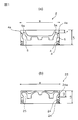
- FIG. 1 (a) is sectional drawing of the piston which concerns on embodiment, (b) is sectional drawing of the conventional piston.
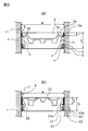
- FIG. 2A is a sectional view of a cylinder having a piston according to the embodiment
- FIG. 2B is a sectional view of a cylinder having a conventional piston.
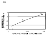
- FIG. 3 is a graph showing the relationship between the groove position L of the top ring and the ratio (%) of dead volume to the combustion chamber volume for the piston according to the embodiment and the conventional piston.
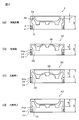
- FIG. 4 is a view showing the crown portions of four types of pistons that have been incorporated into a cylinder of an engine of a practical machine level and tested for performance, and (a) is a cross-sectional view of the piston according to the embodiment.
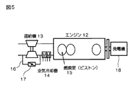
- FIG. 5 is a schematic diagram showing the configuration of a practical-level engine incorporating the pistons shown in FIG.
- FIG. 6 is a graph showing the results of a performance test performed with the engine shown in FIG. 4, and is a graph showing the relationship between the excess air ratio and the thermal efficiency.
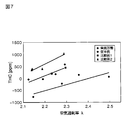
- FIG. 7 is a graph showing the results of a performance test performed on the engine shown in FIG. 4, and is a graph showing the relationship between the excess air ratio and the concentration of THC (total hydrocarbons) in the exhaust.
- FIG. 1A is an embodiment of the present invention, and is a cross-sectional view showing a piston 2 of an industrial engine having a net average effective pressure Pme of 2 MPa, and FIG. It is sectional drawing which shows the conventional piston 22 in the conventional industrial engine which is also 2 Mpa.
- FIG. 2A is a cross-sectional view showing a state in which the piston 2 of the embodiment is in the cylinder 1
- FIG. 2B is a cross-sectional view showing a state in which the conventional piston 22 is in the cylinder 1.
- Each of these pistons is a combination type piston formed by combining a crown and a skirt, and the crown portion is shown, and the skirt portion and the connecting rod are omitted.
- L the distance between the upper surface of the piston 2 and the upper surface of the uppermost circumferential groove 4a is L and the inner diameter of the cylinder 1 is B
- B L
- the ratio of B to B, ie L / B, is designed to be 0.07. That is, the uppermost circumferential groove 4a is provided at a position close to the top surface of the piston 2, and the other two circumferential grooves 4 and a total of two piston rings 3 respectively attached to these circumferential grooves 4 are pistons.
- the cooling chamber 5 is provided inside the piston 2 as in the conventional example shown in FIGS. 1 (b) and 2 (b). A cavity is formed and opened downward, so that lubricating oil adheres when the engine is driven and exhibits a cooling effect.
- the cooling chamber 5 of this embodiment has an upper cooling chamber 5a extending to a position close to the uppermost circumferential groove 4a.
- the upper cooling chamber 5a communicates with the cooling chamber 5 at the lower portion, and the upper portion extends upward from the upper surface of the uppermost circumferential groove 4a, thereby forming a side surface portion of the uppermost circumferential groove 4a.
- the height of the dead volume S shown as a gray area in the drawing that is, the distance between the upper surface of the top ring 23a and the top surface of the piston 2 is large. Therefore, the amount of the air-fuel mixture compressed in the compression stroke and entering the dead volume S in the cylinder 1 in the conventional engine is larger than that in the piston 2 of the embodiment described with reference to FIG. large. Therefore, the amount of the mixed gas in the dead volume S that is not propagated in the expansion stroke, is discharged into the cylinder 1 as unburned gas, and is discharged into the exhaust gas pipe in the exhaust stroke is compared with the conventional example. The form is less.
- the position of the top ring 3a is arranged in the vicinity of the top surface of the piston 2, so that the dead volume S is reduced and the unburned gas discharged The volume could be reduced.
- the cooling chamber 5 in the piston 2 is extended to a position close to the circumferential groove 4a of the top ring 3a to form an upper cooling chamber 5a, so that the top ring 3a and the circumferential groove 4a can be sufficiently cooled.
- the top ring 3a is reliably prevented from sticking into the circumferential groove 4a.
- FIGS. 4A and 4B are diagrams showing the crown portions of the four types of pistons used in this comparative experiment side by side, wherein FIG. 4A is a cross-sectional view of the piston 2 of the embodiment, and FIG. 4B is the conventional example. It is sectional drawing of the piston 22 of. (C) is sectional drawing of the piston 32 of the comparative example 1.
- FIG. 4A is a cross-sectional view of the piston 2 of the embodiment
- FIG. 4B is the conventional example.
- C is sectional drawing of the piston 32 of the comparative example 1.
- the piston 32 of the comparative example 1 has the same height L4 as the piston 2 of the embodiment, but the circumferential groove 34 and the piston ring (not shown) are in the lower half as in the conventional example, and further on the top surface. It has a structure provided with a convex portion 36 as in the conventional example.
- (D) is sectional drawing of the piston 42 of the comparative example 2.
- FIG. The piston 42 of the comparative example 2 has the same height L4 as the piston 2 of the embodiment, but the circumferential groove 44 and the piston ring (not shown) are in the lower half as in the conventional example, and the top surface is It has a concave structure substantially similar to the embodiment.
- the engine 12 which is a practical machine shown in FIG.
- FIG. 5 is a gas engine having 6 cylinders with a cylinder diameter of 220 mm, a rated output of 1070 kW / 1000 min ⁇ 1 , and a net average effective pressure Pme of 2 MPa.
- the engine 12 is provided with a supercharger 13, and the exhaust from the engine 12 drives the turbine of the supercharger 13, thereby driving the compressor to compress air and passing through the air cooler 14 and the engine. 12 combustion chambers 15 can be taken in.
- a bypass line 16 and a valve 17 for adjusting the bypass amount are provided on the air intake side of the supercharger 13 so that the intake amount can be controlled.
- the engine 12 drives a generator 18.
- FIG. 6 shows the points of thermal efficiency with respect to the excess air ratio.
- FIG. 7 shows the concentration of THC (Total Hydrocarbon) in the exhaust by a difference from the standard value.
- the concentration of THC (Total Hydrocarbon) in the exhaust gas is substantially over all excess air ratios compared to the conventional example and Comparative Examples 1 and 2. Is about 500 ppm lower than the standard. 3.
- the inventor sets various different L for the same B (220 mm in this example) in addition to the piston 2 having the structure specifically exemplified in the embodiment.
- a plurality of types of pistons having different structures of / B and having a cooling chamber provided in the vicinity of the peripheral groove of the top ring were manufactured.
- the inventor conducted an experiment similar to “2. Comparison of engine performance” with respect to these plural types of pistons. As a result, as described below, it is necessary to obtain an engine performance that is capable of reducing the volume of unburned gas discharged as the dead volume S becomes smaller as compared to the conventional example, and having excellent thermal efficiency.
- the L / B conditions were finalized.
- the conventional problem cannot be solved simply by adopting an unprecedented special structure in which the upper cooling chamber is formed in the vicinity of the circumferential groove.
- an excellent effect is obtained in comparison with the conventional example in the thermal efficiency and the THC concentration in the exhaust gas, and a further structural feature for preventing the top ring from sticking, that is, a further essential feature as an invention. The condition could be confirmed.
- the point of thermal efficiency with respect to the value of L / B (value expressed as a percentage of improvement from the reference value as described in FIG. 6) is shown in the following correspondence table. Street. Point of L / B thermal efficiency 0.12 0 0.11 0.6 0.1 0.7 0.09 0.8 0.07 1.0 (Numerical example of embodiment)
- the value of L / B and the point of thermal efficiency are in a proportional relationship. If the value of L / B is decreased, the thermal efficiency is gradually improved, but from a practical standpoint, it is 0.6. Improvement of points is insufficient, and improvement of 0.7 points or more is necessary.
Landscapes
- Engineering & Computer Science (AREA)
- General Engineering & Computer Science (AREA)
- Mechanical Engineering (AREA)
- Chemical & Material Sciences (AREA)
- Combustion & Propulsion (AREA)
- Physics & Mathematics (AREA)
- Fluid Mechanics (AREA)
- Pistons, Piston Rings, And Cylinders (AREA)
Abstract
Description
これらのピストンリング23のうち、最も上に配置されるトップリング23aのための周溝24aの位置L2は、従来はピストン22の高さL5の略半分の位置(これはシリンダの直径に対して概略20%に相当する位置である)に形成されており、その他の2本の周溝24及びピストンリング23はこれよりも下方に配置されていた。これは、ピストンリング23の周辺には潤滑油があるため、シリンダ1内の燃焼による熱でこの潤滑油が炭化し、これがトップリング23aと周溝24aの間に堆積してトップリング23aが膠着して動けなくなってしまうことがあり、このような不都合が生じないようにするために、経験工学的な見地から、トップリング23aの周溝24aの位置L2を上述したようにピストン22の高さL5の略半分の位置(前述したようにシリンダの直径に対して概略20%に相当する位置)に定めたものである。
下記特許文献1には、上述したようなピストンの構造が開示されている。
上述したデッドボリウムSに起因して未燃ガスとして排出される混合ガスは、例えばガスエンジンにおいて都市ガスを燃料とした場合には、メタンを90%程度含んでいる。このため、燃料経済性及びメタンが有する地球温暖化効果を考慮すると、未燃ガスの排出抑制は社会的要請であるといえる。
しかしながら、従来のピストン22におけるピストンリング23の位置は、前述した通り、燃焼による熱で潤滑油が炭化してトップリング23aが膠着するのを防止することを目的として経験工学的に設定されたものであり、ピストンリング23の位置と未燃ガスの排出との関係については研究が進んでおらず、従来はデッドボリウムSを改善して未燃ガスの排出を抑制しつつ、かつトップリング23aの膠着も防止できるような具体的な提案は皆無であった。
デッドボリウムSを減少させるために、トップリング23aの位置をより高くして燃焼面に近づけるとの発想は机上では可能であるものの、高出力かつ高燃焼圧力(例えば15MPa程度)の産業用エンジンにおいては、このようなピストンリング配置は直ちにピストンリング23の熱負荷による膠着を発生させることが明らかであることから、実際には検証例がなく、結局、ピストンリング23の位置と未燃ガスの排出の関係、そしてこれらがエンジン熱効率にどのような影響を与えるかについては何らの知見も知られていなかった。
本発明は、上述した従来の問題点を解決することを目的としており、所謂デッドボリウムに閉じ込められて未燃ガスとして排出される燃料混合気の量が少なくて済み、かつピストンリングが熱負荷によってシリンダに膠着するおそれが少なく、さらに熱効率が従来よりも改善されるピストンと、係るピストンを備えたエンジンを提供することを目的としている。
ピストンリングを設ける複数の周溝が外周面に形成されているピストンにおいて、
前記ピストンが収納されるシリンダの内径Bと、前記ピストンの上面と最上部の前記周溝の上面の距離Lとの関係が、L/B≦0.1であるとともに、最上部の前記周溝に近接して冷却室が形成されたことを特徴としている。
請求項2に記載されたエンジンは、
外周面に形成された複数の周溝にそれぞれピストンリングが装着されたピストンがシリンダ1内に摺動可能に設けられているエンジンにおいて、
前記ピストンが収納されるシリンダの内径Bと、前記ピストンの上面と最上部の前記周溝の上面の距離Lとの関係が、L/B≦0.1であるとともに、最上部の前記周溝に近接して冷却室が形成されたことを特徴としている。
請求項3に記載のエンジンは、
前記エンジンが、正味平均有効圧Pmeが1.8MPa以上のガスエンジンであることを特徴としている。
図2(a)は実施形態に係るピストンを有するシリンダの断面図、(b)は従来のピストンを有するシリンダの断面図である。
図3は実施形態に係るピストンと従来のピストンについて、トップリングの溝位置Lと、燃焼室容積に対するデッドボリウムの割合(%)との関係を示すグラフである。
図4は実用機レベルのエンジンのシリンダに組み込んで性能試験を行なった4種類のピストンの各クラウン部分を並べて示した図であって、(a)は実施形態に係るピストンの断面図、(b)は従来例のピストンの断面図、(c)は比較例1のピストンの断面図、(d)は比較例1のピストンの断面図である。
図5は図4に示した各ピストンを組み込んだ実用機レベルのエンジンの構成を示す模式図である。
図6は図4に示したエンジンで行なった性能試験の結果を示す図であり、空気過剰率と熱効率の関係を示すグラフである。
図7は図4に示したエンジンで行なった性能試験の結果を示す図であり、空気過剰率と排気中のTHC(総炭化水素)の濃度の関係を示すグラフである。
図1(a)は、本発明の実施形態であって、正味平均有効圧Pmeが2MPaである産業用エンジンのピストン2を示す断面図であり、同図(b)は正味平均有効圧Pmeが同じく2MPaである従来の産業用エンジンにおける従来のピストン22を示す断面図である。
図2(a)は、実施形態のピストン2がシリンダ1内にある状態を示す断面図であり、同図(b)は従来のピストン22がシリンダ1内にある状態を示す断面図である。
なお、これらのピストンは、いずれもクラウンとスカートを組み合わせてなる組み合わせ型ピストンであり、そのクラウン部分を示しており、スカート部分やコンロッド等は省略している。
図1(a)及び図2(a)に示す実施形態のピストン2では、ピストン2の上面と最上部の周溝4aの上面との距離をLとし、シリンダ1の内径をBとすると、LのBに対する比率、すなわちL/Bは、0.07と設計されている。すなわち、最上部の周溝4aはピストン2の頂面に近接した位置に設けられ、その他の2本の周溝4及びこれら周溝4にそれぞれ装着される合計2本のピストンリング3は、ピストン2の下端に近接した位置に設けられる。
これに対し、図1(b)及び図2(b)に示す従来例のピストン22では、3本の周溝24と、各周溝24に1本ずつ装着される合計3本のピストンリング23の配置は次のように設定されている。すなわち、ピストン22の直径をBとし、ピストン22の上面と最上部の周溝24aの上面との距離をL2とすると、L2/B=0.17となるように設計されている。このように、実施形態のピストン2では、L/Bの値が従来例に比べて小さく設定されている。
さらに、図1(a)及び図2(a)に示す実施形態のピストン2では、図1(b)及び図2(b)に示す従来例と同様に、ピストン2の内部には冷却室5となる空洞が形成されて下方に開放されており、エンジンの駆動時に潤滑油が付着して冷却効果を奏するようになっている。しかしながら、この実施形態の冷却室5は、従来例の冷却室25とは異なり、最上部の周溝4aに近接する位置にまで延設された上部冷却室5aを有している。この上部冷却室5aは、下方部で冷却室5に連通するとともに、上方部は最上部の周溝4aの上面よりも上方にまで伸びており、これによって最上部の周溝4aの側面部に対し、例えば同溝の深さ程度の肉厚の壁を挟んで周状の配置により全面で対面している。従って、最上部の周溝4a及びこれに装着されるトップリング3aが、ピストン2の頂面に近い位置においてエンジンの燃焼時に燃焼ガスから大きな熱を受けても、その全周にわたって冷却室5及び上部冷却室5aにより効果的に冷却されるので、この部分で潤滑油が炭化してピストンリング3が周溝4内に膠着するような不都合は確実に防止される。
図2(a)に示す実施形態のピストン2では、前述したようにL/B≒0.07としており、最上部の周溝4aをピストン2の頂面に近接した位置に設けているので、図2(a)中にグレー領域として示したデッドボリウムS、すなわちピストン2とシリンダライナ11とトップリング3aの間の空間は、従来例のピストン22のL2/B=0.17よりも狭い。従って、圧縮行程で圧縮されてデッドボリウムS中に入り込む混合気の量は図2(b)を参照して説明した従来例のピストン22の場合に比べて少ない。
すなわち、図2(b)に示す従来例のピストン22では、前述したように、L2/Bの値が実施形態に比べて大きい。これは、同図中にグレー領域として示したデッドボリウムSの高さ、すなわちトップリング23aの上面とピストン2の頂面との距離が大きいことを意味する。従って、従来例のエンジンにおいて圧縮行程で圧縮されてシリンダ1内のデッドボリウムS中に入り込む混合気の量は、図2(a)を参照して説明した実施形態のピストン2の場合に比べて大きい。
従って、膨張行程において火炎が伝播せず、未燃ガスとしてシリンダ1内に排出され、排気行程で排気ガス管内に放出されてしまうデッドボリウムS内の混合ガスの量は、従来例に比べて実施形態の方が少なくなっている。本例における比較では、両者はシリンダ径が同一であり、同一レベルの出力のエンジンであることを前提としているが、図3に示すように、トップリングの位置が異なるために、デッドボリウムSの燃焼室容積に対する割合は、従来例のエンジン(点b)では1.4%にもなるが、実施形態のエンジン(点a)では0.8%となっており、トップリングの位置Lが減少するにつれて、デッドボリウムSの燃焼室容積に対する割合も減少している。詳細は具体的な実験データに基づいて次項にて後述するが、デッドボリウムSの燃焼室容積に対する割合の減少に応じて、排出される未燃ガスの容積も減少する。
このように、実施形態のピストン2乃至これを有するエンジンによれば、トップリング3aの位置をピストン2の頂面の近傍に配置したので、デッドボリウムSが小さくなって排出される未燃ガスの容積を減少させることができた。また、トップリング3aの周溝4aに近接した位置までピストン2内の冷却室5を延設して上部冷却室5aとし、トップリング3a及びその周溝4aを十分に冷却できるようにしたので、トップリング3aが周溝4a内に膠着することは確実に防止される。
2.エンジン性能の比較(図4~図7)
次に、実施形態のピストン2と、従来例のピストン22を、実際に実用機エンジンに設けて運転し、エンジン性能を比較した結果について説明する。
図4は、この比較実験に使用した4タイプのピストンの各クラウン部分を並べて示した図であって、(a)は前記実施形態のピストン2の断面図であり、(b)は前記従来例のピストン22の断面図である。(c)は比較例1のピストン32の断面図である。比較例1のピストン32は、実施形態のピストン2と同一の高さL4であるが、周溝34及びピストンリング(図示せず)は従来例のように下半部にあり、さらに頂面に従来例のような凸部36を設けた構造となっている。(d)は比較例2のピストン42の断面図である。比較例2のピストン42は、実施形態のピストン2と同一の高さL4であるが、周溝44及びピストンリング(図示せず)は従来例のように下半部にあり、さらに頂面は実施形態と略同様の凹状の構造となっている。
図5に示す実用機であるエンジン12は、シリンダ径が220mmの6気筒であり、定格出力が1070kW/1000min−1、正味平均有効圧Pmeが2MPaのガスエンジンである。このエンジン12には過給機13が設けられており、エンジン12からの排気が過給機13のタービンを駆動し、これによってコンプレッサを駆動して空気を圧縮し、空気冷却器14を経てエンジン12の燃焼室15に取り込むことができる。過給機13の空気吸入側には、バイパスライン16とバイパス量を調整する弁17が設けられており、吸気量を制御できるようになっている。このエンジン12は発電機18を駆動するようになっている。
図6は、空気過剰率に対する熱効率のポイントを示しており、例えば基準の熱効率が50%であるとした場合、計測した熱効率が52%の場合には2ポイントと表示される。図6に示すように、実施形態のエンジン(黒丸で示す)によれば、従来例や比較例1、2に比べて、概ねすべての空気過剰率にわたって熱効率が高く、基準値に対して約1ポイント改善している。
図7は、排気中のTHC(Total Hidrocarbon)の濃度を標準値との差異で示している。図7に示すように、実施形態のエンジン(黒丸で示す)によれば、従来例や比較例1、2に比べて、概ねすべての空気過剰率にわたって、排気中のTHC(Total Hidrocarbon)の濃度が低く、標準よりも約500ppm低下している。
3.本発明のピストンの構造上の特徴
本発明者は、実施形態で具体的に例示した構造のピストン2の他、同一のB(本例では220mm)に対して異なる種々のLを設定し、L/Bの値が異なるとともに、トップリングの周溝の近傍に冷却室が設けられた構造である複数種類のピストンを製作した。本発明者は、これら複数種類のピストンについて、「2.エンジン性能の比較」と同様の実験を行なった。その結果、以下に説明するように、従来例と比較し、デッドボリウムSが小さくなって排出される未燃ガスの容積を減少させることができるとともに熱効率にも優れたエンジン性能を得るために必要なL/Bの条件を確定するに至った。
すなわち本発明者の実験によれば、L/Bの値が0.1を越えると、従来例等と比較して排出される未燃ガスの量に有意の改善が認められなくなった。これは、デッドボリウムSが無用に大きくなっているためと考えられる。また、L/Bの値が0.1を越えると、熱効率についても従来例等と比較して満足な改善結果が得られなくなり、トップリングの膠着が生じるようになった。
このように、複数の周溝が外周面に形成され、各周溝にそれぞれピストンリングが装着されているピストンにおいて、最上部の周溝をピストンの頂面に近接して設け、かつ最上部の周溝に近接して上部冷却室を形成するという従来にない特殊な構造を採用したというだけでは、必ずしも従来の課題を解決することはできない。
上記実験の結果、熱効率や排気中のTHC濃度において従来例に比べて優れた効果が得られ、しかもトップリングの膠着が起きないための更なる構成上の特徴、すなわち発明としての更なる必須の条件を確定することができた。すなわち、上記特殊な構造において、ピストンが収納されるシリンダの内径Bと、ピストンの上面と最上部の周溝の上面の距離Lとの関係が、L/B≦0.1である場合には、排出される未燃ガスの量が従来に比べて減少し、熱効率も改善され、トップリングの膠着が起きないことが判明した。なお、前述した通り、「1.従来例と比較して示した実施形態の構成」の実施形態では、L/Bの値は上記条件を満たす約0.07であり、上記条件を満たしている。
本発明者が行なった実験の結果によれば、L/Bの値に対する熱効率のポイント(図6で説明したような基準値からの改善度を%で表した値)は、次の対応表の通りである。
L/B 熱効率のポイント
0.12 0
0.11 0.6
0.1 0.7
0.09 0.8
0.07 1.0(実施形態の数値例)
このように、L/Bの値と熱効率のポイントは比例関係にあり、L/Bの値を小さくしていけば熱効率は徐々に改善されていくが、実用的な見地から見れば0.6ポイントの改善では不十分であり、0.7ポイント以上の改善が必要である。これは、熱効率の改善による燃費の向上及びこれによる運転コストの低減と、本発明を採用したことによるピストン乃至エンジンの製造コストの増大とを、長期的な運用を前提として比較考量した場合、前記熱効率のポイントが0.7以上でないと発明を実施する実益が得られないからである。L/Bの値が0.1以下であれば、前記熱効率のポイントが0.7以上となり、実効性のある熱効率の改善が達成でき、産業上実用的な効果を得ることができる。
また本発明者等の知見によれば、従来構造のピストンを備えたガスエンジンであって、Pme(正味平均有効圧)が1.8MPa以上の効率が高いガスエンジンにおいては、本発明以外の手段を用いて前記熱効率のポイントを0.7以上とすることは困難であり、現実にそのようなガスエンジンは存在しない。ところが、本発明の実施形態における実験の結果によれば、Pme(正味平均有効圧)が1.8MPa以上である高効率のガスエンジンであっても、そのピストンを実施形態のようなL/Bの値が0.1以下であるピストンに交換することにより、上述したように前記熱効率を0.7以上のポイントで改善することが可能であることが判明した。
4.実施形態の効果
1)本実施形態によれば、トップリングの冷却を強化することにより、トップリングの位置をL/B≦0.1としても、エンジンの定格運転が可能である。
2)上記効果1)により、トップリングの膠着を回避して、BMEP(Brake Mean Effective Pressure:正味平均有効圧力)が1.8MPa以上の高圧力、例えば2.0MPa(世界最高レベルの圧力)での運転が可能となる。
3)未燃排出物(都市ガスの場合、メタンが90%程度)の抑制効果が得られ、燃料経済性及びメタンによる地球温暖化を抑制する効果が得られる。
2…ピストン
3…ピストンリング
3a…トップリング
4…周溝
4a…最上部の周溝
5…冷却室
5a…上部冷却室
11…シリンダライナ
22…従来例のピストン
32…比較例1のピストン
42…比較例2のピストン
S…デッドボリウム
Claims (3)
- ピストンリングを設ける複数の周溝が外周面に形成されているピストンにおいて、
前記ピストンが収納されるシリンダの内径Bと、前記ピストンの上面と最上部の前記周溝の上面の距離Lとの関係が、L/B≦0.1であるとともに、
最上部の前記周溝に近接して冷却室が形成されたことを特徴とするピストン。 - 外周面に形成された複数の周溝にそれぞれピストンリングが装着されたピストンがシリンダ内に摺動可能に設けられているエンジンにおいて、
前記ピストンが収納されるシリンダの内径Bと、前記ピストンの上面と最上部の前記周溝の上面の距離Lとの関係が、L/B≦0.1であるとともに、
最上部の前記周溝に近接して冷却室が形成されたことを特徴とするエンジン。 - 前記エンジンが、正味平均有効圧Pmeが1.8MPa以上のガスエンジンである請求項2記載のエンジン。
Priority Applications (5)
| Application Number | Priority Date | Filing Date | Title |
|---|---|---|---|
| CN2010800471531A CN102575612A (zh) | 2009-10-19 | 2010-08-02 | 活塞及发动机 |
| US13/499,173 US20120180653A1 (en) | 2009-10-19 | 2010-08-02 | Piston and engine |
| KR1020127012255A KR20120089316A (ko) | 2009-10-19 | 2010-08-02 | 피스톤 및 엔진 |
| IN3228DEN2012 IN2012DN03228A (ja) | 2009-10-19 | 2010-08-02 | |
| EP10824716.4A EP2492482A4 (en) | 2009-10-19 | 2010-08-02 | PISTON AND MOTOR |
Applications Claiming Priority (2)
| Application Number | Priority Date | Filing Date | Title |
|---|---|---|---|
| JP2009240566A JP2011085109A (ja) | 2009-10-19 | 2009-10-19 | ピストン及びエンジン |
| JP2009-240566 | 2009-10-19 |
Publications (1)
| Publication Number | Publication Date |
|---|---|
| WO2011048864A1 true WO2011048864A1 (ja) | 2011-04-28 |
Family
ID=43900104
Family Applications (1)
| Application Number | Title | Priority Date | Filing Date |
|---|---|---|---|
| PCT/JP2010/063442 Ceased WO2011048864A1 (ja) | 2009-10-19 | 2010-08-02 | ピストン及びエンジン |
Country Status (7)
| Country | Link |
|---|---|
| US (1) | US20120180653A1 (ja) |
| EP (1) | EP2492482A4 (ja) |
| JP (1) | JP2011085109A (ja) |
| KR (1) | KR20120089316A (ja) |
| CN (1) | CN102575612A (ja) |
| IN (1) | IN2012DN03228A (ja) |
| WO (1) | WO2011048864A1 (ja) |
Families Citing this family (1)
| Publication number | Priority date | Publication date | Assignee | Title |
|---|---|---|---|---|
| DE102013009415A1 (de) * | 2013-06-05 | 2014-12-11 | Man Diesel & Turbo Se | Kolben einer Brennkraftmaschine |
Citations (3)
| Publication number | Priority date | Publication date | Assignee | Title |
|---|---|---|---|---|
| JPH03502720A (ja) * | 1988-10-21 | 1991-06-20 | キャタピラー インコーポレーテッド | エンジンピストン組立体及び冷却凹部を有する鍛造ピストン部材 |
| JPH064349U (ja) * | 1992-06-22 | 1994-01-21 | 株式会社リケン | ハイトップリングピストン |
| JP2005194971A (ja) | 2004-01-09 | 2005-07-21 | Mitsubishi Heavy Ind Ltd | ガスエンジンのピストン |
Family Cites Families (7)
| Publication number | Priority date | Publication date | Assignee | Title |
|---|---|---|---|---|
| US3476021A (en) * | 1968-01-15 | 1969-11-04 | Gen Motors Corp | Bearing assembly with prestressing and retaining means |
| US4608947A (en) * | 1985-07-05 | 1986-09-02 | Klockner-Humboldt-Deutz Aktiengesellschaft | Arrangement for cooling pistons and cylinder sleeves |
| JP2563402Y2 (ja) * | 1989-09-28 | 1998-02-25 | 株式会社小松製作所 | ディーゼルエンジンのピストン |
| US5906182A (en) * | 1997-03-25 | 1999-05-25 | General Motors Corporation | Engine piston |
| CN101006255B (zh) * | 2004-06-24 | 2011-05-04 | 伍德沃德控制器公司 | 预燃室火花塞 |
| JP2009185745A (ja) * | 2008-02-07 | 2009-08-20 | Nissan Motor Co Ltd | 内燃機関用ピストン |
| DE102008011922A1 (de) * | 2008-02-29 | 2009-09-03 | Ks Kolbenschmidt Gmbh | Kolben für Brennkraftmaschinen, hergestellt mittels eines Multi-Orbitalen Reibschweißverfahrens |
-
2009
- 2009-10-19 JP JP2009240566A patent/JP2011085109A/ja active Pending
-
2010
- 2010-08-02 IN IN3228DEN2012 patent/IN2012DN03228A/en unknown
- 2010-08-02 EP EP10824716.4A patent/EP2492482A4/en not_active Withdrawn
- 2010-08-02 WO PCT/JP2010/063442 patent/WO2011048864A1/ja not_active Ceased
- 2010-08-02 US US13/499,173 patent/US20120180653A1/en not_active Abandoned
- 2010-08-02 CN CN2010800471531A patent/CN102575612A/zh active Pending
- 2010-08-02 KR KR1020127012255A patent/KR20120089316A/ko not_active Withdrawn
Patent Citations (3)
| Publication number | Priority date | Publication date | Assignee | Title |
|---|---|---|---|---|
| JPH03502720A (ja) * | 1988-10-21 | 1991-06-20 | キャタピラー インコーポレーテッド | エンジンピストン組立体及び冷却凹部を有する鍛造ピストン部材 |
| JPH064349U (ja) * | 1992-06-22 | 1994-01-21 | 株式会社リケン | ハイトップリングピストン |
| JP2005194971A (ja) | 2004-01-09 | 2005-07-21 | Mitsubishi Heavy Ind Ltd | ガスエンジンのピストン |
Non-Patent Citations (1)
| Title |
|---|
| See also references of EP2492482A4 * |
Also Published As
| Publication number | Publication date |
|---|---|
| KR20120089316A (ko) | 2012-08-09 |
| EP2492482A1 (en) | 2012-08-29 |
| JP2011085109A (ja) | 2011-04-28 |
| IN2012DN03228A (ja) | 2015-10-23 |
| CN102575612A (zh) | 2012-07-11 |
| EP2492482A4 (en) | 2013-05-08 |
| US20120180653A1 (en) | 2012-07-19 |
Similar Documents
| Publication | Publication Date | Title |
|---|---|---|
| KR102068372B1 (ko) | 엔진 피스톤 | |
| WO2009038044A1 (ja) | ディーゼルエンジン | |
| US4106463A (en) | Double taper piston | |
| CN101614278A (zh) | 一种碳素材料与金属材料组合式活塞 | |
| WO2016041298A1 (zh) | 一种二冲程内燃机 | |
| KR102077376B1 (ko) | 4행정 내연 엔진 및 4행정 내연 엔진용 피스톤 | |
| JP6389865B2 (ja) | 内燃機関用ピストン | |
| WO2011048864A1 (ja) | ピストン及びエンジン | |
| CN102518525A (zh) | 一种气缸套 | |
| KR102741817B1 (ko) | 내연 기관의 피스톤 및 실린더 그리고 내연 기관 | |
| US9194327B2 (en) | Cylinder liner with slots | |
| US8069833B2 (en) | Reciprocating engine | |
| CN202451290U (zh) | 一种气缸套 | |
| US20170030290A1 (en) | Recess to encourage ring lift | |
| JP5316449B2 (ja) | 内燃機関の燃焼室構造 | |
| US6837205B1 (en) | Internal combustion engine | |
| RU2372506C2 (ru) | Поршневое уплотнение для двигателя внутреннего сгорания | |
| JP6514216B2 (ja) | ピストンリング溝、特にコンプレッション溝を有するピストン | |
| CN108644027A (zh) | 气体机的钢活塞 | |
| CN200943533Y (zh) | 带有减磨环的内燃机车柴油机气缸 | |
| CN202300692U (zh) | 发动机第二道气环 | |
| RU2372508C1 (ru) | Цилиндропоршневая группа двигателя внутреннего сгорания | |
| KR102242925B1 (ko) | 탑 랜드 높이가 감소되고 타이트 탑 랜드 피스톤 프로파일을 지닌 피스톤 | |
| CN202746029U (zh) | 一种高密封带贮油环槽的铝活塞 | |
| CN201045316Y (zh) | 汽车发动机活塞节能环 |
Legal Events
| Date | Code | Title | Description |
|---|---|---|---|
| WWE | Wipo information: entry into national phase |
Ref document number: 201080047153.1 Country of ref document: CN |
|
| 121 | Ep: the epo has been informed by wipo that ep was designated in this application |
Ref document number: 10824716 Country of ref document: EP Kind code of ref document: A1 |
|
| WWE | Wipo information: entry into national phase |
Ref document number: 13499173 Country of ref document: US |
|
| WWE | Wipo information: entry into national phase |
Ref document number: 3228/DELNP/2012 Country of ref document: IN |
|
| WWE | Wipo information: entry into national phase |
Ref document number: 2010824716 Country of ref document: EP |
|
| ENP | Entry into the national phase |
Ref document number: 20127012255 Country of ref document: KR Kind code of ref document: A |