WO2011049046A1 - 画像処理装置、画像処理方法、画像処理プログラム、および、記録媒体 - Google Patents
画像処理装置、画像処理方法、画像処理プログラム、および、記録媒体 Download PDFInfo
- Publication number
- WO2011049046A1 WO2011049046A1 PCT/JP2010/068281 JP2010068281W WO2011049046A1 WO 2011049046 A1 WO2011049046 A1 WO 2011049046A1 JP 2010068281 W JP2010068281 W JP 2010068281W WO 2011049046 A1 WO2011049046 A1 WO 2011049046A1
- Authority
- WO
- WIPO (PCT)
- Prior art keywords
- image
- ellipse
- image processing
- polygon
- center candidate
- Prior art date
- Legal status (The legal status is an assumption and is not a legal conclusion. Google has not performed a legal analysis and makes no representation as to the accuracy of the status listed.)
- Ceased
Links
Images


Classifications
-
- H—ELECTRICITY
- H04—ELECTRIC COMMUNICATION TECHNIQUE
- H04N—PICTORIAL COMMUNICATION, e.g. TELEVISION
- H04N1/00—Scanning, transmission or reproduction of documents or the like, e.g. facsimile transmission; Details thereof
- H04N1/387—Composing, repositioning or otherwise geometrically modifying originals
- H04N1/3877—Image rotation
- H04N1/3878—Skew detection or correction
-
- G—PHYSICS
- G06—COMPUTING OR CALCULATING; COUNTING
- G06T—IMAGE DATA PROCESSING OR GENERATION, IN GENERAL
- G06T3/00—Geometric image transformations in the plane of the image
Definitions
- the present invention relates to the technical field of an image processing apparatus, an image processing method, an image processing program, and a recording medium that perform image conversion on image data.
- Patent Document 1 discloses an image obtained by photographing a white board as a photographing object in order to obtain an image as if it was photographed from the front by correcting an image of the photographing object such as a letter written on a document or a white board. From the acquired contour, a contour is obtained, a straight line that is a candidate for forming a white plate image is detected from the obtained contour, a square shape of the white plate is obtained, and the white plate image and the actual image are obtained from the vertex positions of the square.
- An image processing apparatus that obtains a projection parameter indicating a relationship with a white plate and performs projective transformation on the image of the white plate is disclosed.
- the shooting target is corrected using a straight line of a document or the like as a clue. Therefore, when shooting a shooting target such as a flower having almost no straight line portion, the shooting target is corrected and the shooting target is corrected. It is difficult to obtain an image as if it was taken.
- the present invention has been made in view of such a problem, and an example of the problem is an image processing apparatus that converts a target image without a straight line outline into an image displayed in a desired direction.
- An object is to provide an image processing method, an image processing program, and a recording medium.
- the invention according to claim 1 is an image processing apparatus that performs image processing on a target image, and includes an ellipse calculation unit that calculates an ellipse that approximates the target image, and the target Center candidate determination means for determining a center candidate of an image, polygon calculation means for calculating the ellipse and a first polygon related to the center candidate, and an ellipse centered on a point at which the center candidate is projectively transformed A projective transformation matrix calculating means for calculating a projective transformation matrix for projectively transforming the first polygon into a second associated polygon; and a transform for obtaining a transformed image by performing projective transformation on the target image based on the projective transformation matrix. And an image acquisition means.
- the projective transformation matrix calculating means includes a second polygon in which an ellipse centered on a point where the center candidate is projective transformed is inscribed or circumscribed. A projective transformation matrix for projectively transforming the first polygon is calculated.
- the invention according to claim 3 is an image processing apparatus characterized in that an ellipse centered at a point at which the center candidate in the projective transformation matrix calculating means is projectively transformed is a perfect circle.
- the polygon calculation means contacts a point of intersection between the straight line passing through the center candidate and the ellipse.
- the first polygon is calculated as follows.
- the polygon calculation means obtains a straight line passing through the center candidate from a straight line parallel to the major axis of the ellipse. .
- the polygon calculation means is such that a straight line parallel to any side of an image frame surrounding the target image and the ellipse are in contact with each other. Is the contact point.
- the polygon calculation means calculates a quadrangle associated with the ellipse and the center candidate
- the projective transformation matrix calculating means calculates a projective transformation matrix for projectively transforming the quadrangle into a square related to an ellipse centered at a point where the center candidate is projectively transformed.
- the central candidate determining unit includes the central candidate image including the central candidate from the target image.
- the center candidate is determined from the intersection of the major axis and the minor axis of an ellipse obtained by ellipse approximation of the extracted center candidate image.
- the invention according to claim 9 is the image processing apparatus according to any one of claims 1 to 8, wherein the target image is a flower image, and the ellipse calculation means approximates the flower image. The ellipse is calculated, and the center candidate determining means determines the center candidate of the flower image from the center of the flower image.
- the image processing apparatus further includes an image acquisition unit that acquires an image including the target image. .
- the invention according to claim 11 is the image processing apparatus according to claim 10, further comprising target image extraction means for extracting the target image from the acquired image.
- a twelfth aspect of the present invention is the image processing apparatus according to any one of the first to eleventh aspects, further comprising search means for searching for information specifying the target image based on the converted image. It is characterized by that.
- the search unit extracts the feature amount of the image from the converted image and specifies the target image based on the feature amount. It is characterized by searching.
- the invention according to claim 14 is the image processing apparatus according to any one of claims 1 to 13, wherein the second polygon is a regular polygon.
- the invention according to claim 15 is the image processing apparatus according to any one of claims 1 to 14, further comprising a storage means for storing the target image.
- the invention according to claim 16 is an image processing method for performing image processing on a target image, the ellipse calculating step for calculating an ellipse that approximates the target image, and the center of the target image after the image processing
- a center candidate determining step for determining a candidate for determining a candidate
- a polygon calculating step for calculating the ellipse and a first polygon related to the center candidate and a second candidate related to an ellipse centered on a point where the center candidate is projectively transformed.
- a projective transformation matrix calculating step for calculating a projective transformation matrix for projectively transforming the first polygon into two polygons; and a transformed image obtaining step for performing a projective transformation on the target image based on the projective transformation matrix to obtain a transformed image. It is characterized by having.
- the invention according to claim 17 is an ellipse calculation unit that calculates an ellipse that approximates a target image of image processing, a center candidate determination unit that determines a center candidate of the target image after the image processing, the ellipse and A polygon calculating means for calculating a first polygon related to the center candidate; a projection for projectively converting the first polygon to a second polygon related to an ellipse centered on a point at which the center candidate is projectively transformed; Projection transformation matrix calculation means for calculating a transformation matrix and projective transformation of the target image based on the projection transformation matrix to function as converted image acquisition means for obtaining a converted image.
- an ellipse calculation unit that calculates an ellipse that approximates a target image for image processing, a center candidate determination unit that determines a center candidate of the target image after the image processing, the ellipse and A polygon calculating means for calculating a first polygon related to the center candidate; a projection for projectively converting the first polygon to a second polygon related to an ellipse centered on a point at which the center candidate is projectively transformed; A projection transformation matrix calculation means for calculating a transformation matrix, and an image processing program that functions as a transformation image acquisition means for projecting and transforming the target image based on the projection transformation matrix to obtain a transformation image
- the computer-readable recording medium that calculates an ellipse that approximates a target image for image processing, a center candidate determination unit that determines a center candidate of the target image after the image processing, the ellipse and A polygon calculating means for calculating a first polygon related to the center candidate; a projection for projectively converting
- a target image to be subjected to image processing is stored, an ellipse that approximates the target image is calculated, a center candidate of the target image is determined, a first polygon related to the ellipse and the center candidate is calculated, A projective transformation matrix for projectively transforming the first polygon to a second polygon related to an ellipse centered on the point at which the center candidate is projectively transformed is calculated, and the stored target image is projectively transformed based on the projective transformation matrix.
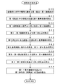
- FIG. 5 It is a schematic diagram which shows a mode that the candidate image was extracted. It is a schematic diagram which shows an example of the target image by which projective transformation was carried out. It is a flowchart which shows an example of the search process in the search server of FIG. 5 is a flowchart illustrating an example of a subroutine for conversion to a standard image in the flowchart of FIG. 4.
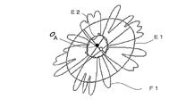
- A is a schematic diagram illustrating an example of an outline of the target image of FIG. 5 and an ellipse that approximates the target image
- (B) is a center candidate image and a center candidate image including a center candidate extracted from the target image. It is a schematic diagram which shows an example of the ellipse which approximates.
- FIG. 9 It is a schematic diagram which shows the relationship between the ellipse of FIG. 9 (A) and the ellipse of FIG. 9 (B). It is a schematic diagram which shows the relationship between the object image of FIG. 5, and the rectangle which touches an ellipse. It is a schematic diagram which shows the mode of the projective transformation from an ellipse to a perfect circle, Comprising: (A) is a schematic diagram which shows the rectangle which touches an ellipse, (B) is a schematic diagram which shows the mode after projective transformation. (A) is a schematic diagram which shows the plane for demonstrating a projective transformation matrix, (B) is a schematic diagram which shows the plane for demonstrating the projective transformation of a quadratic curve. FIG.
- FIG. 9 is a flowchart illustrating an example of a square calculation subroutine in the flowchart of FIG. 8.
- FIG. It is a flowchart which shows an example of the square calculation subroutine in the 1st, 2nd modification which calculates
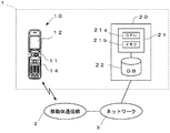
- FIG. 1 is a schematic diagram showing a schematic configuration example of an image search system according to an embodiment of the present invention.
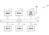
- FIG. 2 is a block diagram showing an example of a schematic configuration of the mobile terminal of FIG.
- an image search system 1 as an example of an image processing apparatus includes a mobile terminal 10 that captures a subject to be imaged, such as a portable wireless telephone, and an image search that performs a search based on image data from the mobile terminal 10. And a server 20.
- the mobile terminal 10 that functions as an example of an image processing apparatus includes an imaging unit 11 that captures an imaging target, a display unit 12 that displays captured images, and a wireless that performs transmission and reception with a wireless base station.
- a communication unit 13, an operation unit 14 for inputting numbers, characters, and the like, a storage unit 15 for storing captured images, and a control unit 16 for performing various controls of the mobile terminal 10 are provided via a bus 17. It is connected.
- the imaging unit 11 includes a digital camera including a CMOS (Complementary Metal Oxide Semiconductor) image sensor, a CCD (charge-coupled device) image sensor, and the like.
- CMOS Complementary Metal Oxide Semiconductor
- CCD charge-coupled device
- the display unit 12 is configured by a liquid crystal display element or an EL (Electro Luminescence) element.
- the wireless communication unit 13 communicates with the image search server 20 through the mobile communication network 2 and the network 3 such as the Internet.
- the operation unit 14 includes various keys. The user moves the pointer displayed on the display unit 12 through the operation unit 14 or selects and confirms an image portion.
- the storage unit 15 includes a RAM (Random Access Memory), a ROM (Read Only Memory), a non-volatile memory such as a flash memory, etc., and a memory in which an image processing program is loaded or image data is stored. A space is formed.
- RAM Random Access Memory
- ROM Read Only Memory
- non-volatile memory such as a flash memory, etc.
- the control unit 16 has a CPU (Central Processing Unit), and executes an image processing program as a computer.
- CPU Central Processing Unit
- the image search server 20 that functions as a computer includes a control unit 21 that controls the entire image search server 20 and performs image processing calculations, and a database 22 in which a database for image search is constructed. .
- control unit 21 includes a CPU 21a that executes a computer program, a RAM 21 that stores a program to be executed, a memory 21b such as a nonvolatile memory such as a flash memory, and the like.
- the CPU 21a of the control unit 21 retrieves information from the database 22 in response to a retrieval request transmitted from the mobile terminal 10, performs image processing for retrieving information from received image data, and manages the database 22. To go.
- a program for executing an image search is developed, received image data is stored, and a calculation result is temporarily stored.
- the database 22 includes a hard disk drive, a silicon disk, and the like, and stores information associated with image feature amounts.
- the database 22 includes string information such as the color of the flower, the number of petals, information on the shape of the whole flower, petal information such as the petal breaks, etc.
- information about flowers such as names and scientific names of flowers and images related to flowers such as flowers, leaves, and fruits are stored.
- the mobile terminal 10 is connected to the mobile communication network 2, the image search server 20 is connected to a network 3 such as the Internet, and the mobile communication network 2 and the network 3 convert protocol, convert language to describe content, etc. Connected by a gateway or the like.
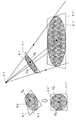
- FIG. 3 is a conceptual diagram showing a concept of how a subject is projected on a photograph when the subject is photographed from the observation point V1.
- the image is deformed so that the flower image taken obliquely from the observation point V1 looks like a front view.
- the flower of the subject is approximated by the ellipse E1 and is on the plane of the quadrangle P1 '.
- each contour line is approximated to an ellipse.
- the ellipse approximating the entire flower corresponds to an ellipse E1
- the center is a point O B.
- the center of the ellipse approximating the flower core corresponds to the point O A.
- projective transformation is performed to obtain a standard image (conversion image) that looks from the front of the flower.
- Projective transformation is equivalent to copying an object in a three-dimensional space onto a film on a two-dimensional plane when compared to a photograph.
- This reverse direction that is, projection from 2D to 3D is generally impossible, but it is possible by limiting some conditions.
- projective transformation from a two-dimensional plane to a two-dimensional plane is performed by assuming that a planar flower exists on a plane (a plane including the quadrangle P1) in the three-dimensional space. Further, to simplify the method, it is assumed that the actual flower shape can be approximated to a perfect circle E1 '.
- the flower cut out in the input image is approximated to an ellipse E1, and a quadrangle P1 circumscribing the ellipse E1 is obtained and used as a deformation target region.
- the transformation target area is projectively transformed into a square P1 'that is a square, the ellipse E1 is projected onto the assumed perfect circle E1'.
- the standard image is an image converted so as to be displayed in a desired direction.
- a standard image is an image in which flowers are displayed at an angle such that the center of the flower is near the center of the whole flower, for example, as long as the image is viewed from an angle that makes it easy to identify the target image such as a flower Good.
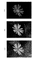
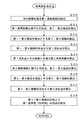
- FIG. 4 is a flowchart showing an example of image processing by the mobile terminal of FIG. 5A is a schematic diagram illustrating an example of an image including a target image
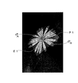
- FIG. 5B is a schematic diagram illustrating a state of the target image extracted from the image
- FIG. 5C is a center candidate from the target image. It is a schematic diagram which shows a mode that the center candidate image containing is extracted.
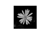
- FIG. 6 is a schematic diagram illustrating an example of a target image subjected to projective transformation.
- the mobile terminal 10 acquires an image to be captured by the imaging unit 11 (step S ⁇ b> 1). Specifically, the control unit 16 of the mobile terminal 10 acquires an image including a target image (flower image) as illustrated in FIG. 5A from the imaging unit 11, and stores image data of the image as a storage unit 15 stored.
- the portable terminal 10 functions as an example of an image acquisition unit that acquires an image including a target image, and also functions as an example of a storage unit that stores a target image for performing image processing.
- the flower of the subject is not photographed from the front.
- the mobile terminal 10 extracts a target image from the acquired image (step S2). Specifically, as shown in FIG. 5B, the control unit 16 obtains the outline of the entire flower and extracts an image of the flower. In FIG. 5B, the entire flower characterized by the petals is drawn by the outline, and the background portion is darkened.
- the user designates a flower portion and a background portion by a pointer displayed on the display unit 12 by the operation unit 14, and based on the color information, The control unit 16 may extract the target image.
- the mobile terminal 10 functions as an example of a target image extraction unit that extracts a target image from the acquired image.
- the target image extraction unit includes at least one foreground pixel on a flower portion (foreground region) included in the acquired image, and a background portion (background region) included in the acquired image.
- Accepting means for accepting designation of at least one background pixel from the user, a divided color space obtained by dividing the three-dimensional color space into a plurality of parts, using the designated foreground pixel and the designated background pixel as reference pixels, respectively.
- a divided color space specifying means for performing a divided color space specifying process for specifying a divided color space to which each reference pixel belongs as a reference divided color space, and a color distance in a color space between each reference pixel and an adjacent pixel adjacent thereto.
- Color distance calculation means for performing a color distance calculation process to be calculated, an attribute determination for determining whether each adjacent pixel belongs to each reference divided color space Attribute determination means for processing, the color distance calculated for each adjacent pixel, and the weight based on the attribute to the reference divided color space determined for each adjacent pixel, and the cost for each adjacent pixel
- the foreground region may be extracted from the acquired image by causing the computer to repeat the color distance calculation process, the affiliation determination process, the cost calculation process, and the confirmation process, and the target image may be extracted.
- the mobile terminal 10 extracts a center candidate image from the target image (step S3).
- the control unit 16 extracts the outline of the flower core portion, which is an example of the center candidate image, in the outline of the entire flower.
- the user designates the petal part and the flower core part by the pointer displayed on the display unit 12 by the operation unit 14, and based on the color information.
- the control unit 16 may extract the target image.
- the mobile terminal 10 functions as an example of a center candidate determination unit that extracts a center candidate image that is an image of a predetermined region including a center candidate from the target image.
- the center candidate image is, for example, an image of a region in the target image that includes the center candidate and whose depth or color information is discontinuously different from the surroundings.
- the mobile terminal 10 converts the target image into a standard image (step S4).
- the control unit 16 converts the target image stored in the storage unit 15 into a standard image obtained by photographing a flower from the front as shown in FIG. .
- the portable terminal 10 functions as an example of a standard image acquisition unit (converted image acquisition unit) that performs a projective conversion on the target image stored in the storage unit based on the projection conversion matrix to acquire a standard image.
- the neighboring image data including the target image is converted into a standard image.
- the mobile terminal 10 transmits a standard image for search to the image search server 20 (step S5). Specifically, in order to search for what kind of flower the photographed flower is, the control unit 16 transmits a standard image as shown in FIG. 6 from the wireless communication unit 13 through the mobile communication network 2 and the network 3. Is transmitted to the image search server 20.
- the mobile terminal 10 receives and displays the search result from the image search server 20 (step S6).
- the control unit 16 receives the searched flower name and flower information from the image search server 20 by the wireless communication unit 13 and displays them on the display unit 12.
- FIG. 7 is a flowchart showing an example of search processing in the image search server 20.
- the image search server 20 receives a standard image from the mobile terminal 10 (step S7). Specifically, the control unit 21 of the image search server 20 receives a standard image from the mobile terminal 10 through the mobile communication network 2 and the network 3.
- the image search server 20 extracts a feature amount from the received standard image (step S8). Specifically, when the target image is a flower image, the control unit 21 uses the number of petals, the color of the flower, information on the shape of the entire flower, petal information such as the petal break, and the like as the feature amount of the standard image. To extract.
- the image search server 20 searches the database 22 for information for specifying the standard image based on the extracted feature amount of the standard image (step S9). Specifically, the control unit 21 searches for a similar flower from the database 22 based on the feature amount of the standard image of the flower, and obtains information about the higher-level flower such as the similarity and an image about the flower. As described above, the image search server 20 functions as an example of a search unit that searches for information specifying a target image based on a standard image. In addition, the image search server 20 functions as an example of a search unit that extracts a feature amount of an image from a standard image and searches for information for specifying a target image based on the feature amount.
- the image search server 20 transmits the upper search result to the mobile terminal 10 (step S10).
- the control unit 21 transmits information related to flowers and images related to flowers.
- the image search server 20 functions as an example of a search unit that searches for information specifying a target image based on a standard image.
- the image search server 20 functions as an example of a search unit that extracts a feature amount of an image from a standard image and searches for information for specifying a target image based on the feature amount.
- the mobile terminal 10 may include a database such as the database 22 of the image search server 20 and search for image information from the standard image.
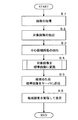
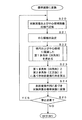
- FIG. 8 is a flowchart showing an example of a subroutine for conversion to a standard image in the flowchart of FIG.
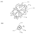
- FIG. 9A is a schematic diagram illustrating an example of an outline of the target image in FIG. 5 and an ellipse that approximates the target image.
- FIG. 9B illustrates a center candidate image including a center candidate extracted from the target image and a center. It is a schematic diagram which shows an example of the ellipse which approximates a candidate image.
- FIG. 10 is a schematic diagram showing the relationship between the ellipse of FIG. 9A and the ellipse of FIG. 9B.
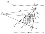
- FIG. 11 is a schematic diagram showing the relationship between the target image of FIG. 5 and a quadrangle that touches the ellipse.
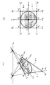
- FIG. 12 is a schematic diagram showing a state of projective transformation from an ellipse to a perfect circle, where (A) is a schematic diagram showing a quadrangle in contact with the ellipse, and (B) is a schematic diagram showing a state after projective transformation. It is.
- the mobile terminal 10 performs ellipse approximation of the target image and the center candidate image (step S20). Specifically, as shown in FIG. 9A, the control unit 16 approximates the contour F1 of the whole flower extracted in step S2 to the ellipse E1 by the least square method, and as shown in FIG. 9B. The outline F2 of the flower core portion extracted in step S3 is approximated to the ellipse E2 by the least square method. As described above, the mobile terminal 10 functions as an example of an ellipse calculation unit that calculates an ellipse that approximates the target image. The ellipse approximation will be described later.
- the mobile terminal 10 determines a center candidate (step S21). More specifically, the control unit 16, as shown in FIG. 9 (B), from the intersection of the long axis E2A and a minor axis E 2 B of the ellipse E2 approximating the flower core, determines the center candidate O A.
- the center candidate O A is the depth information.
- the relationship between the ellipse E1 of the whole flower and the ellipse E2 of the flower core is as shown in FIG.
- the mobile terminal 10 functions as an example of a center candidate determination unit that determines a center candidate of the target image.
- the mobile terminal 10 functions as an example of a center candidate determination unit that determines a center candidate from the intersection of the major axis and the minor axis of an ellipse obtained by ellipse approximation of the extracted center candidate image.
- the mobile terminal 10 functions as an example of an ellipse calculation unit that calculates an ellipse that approximates a flower image when the target image is a flower image.
- the mobile terminal 10 functions as an example of a center candidate determination unit that determines a center candidate of a flower image from the center part of the flower image when the target image is a flower image.
- the mobile terminal 10 obtains a rectangle related to the ellipse and the center candidate (step S22). Specifically, as shown in FIG. 11, the control unit 16 by a center candidate O A of the whole flower ellipse E1 and Hanashin ellipse E2, a rectangle P1 as an example of the first polygon that is in contact with the ellipse E1 Ask. As described above, the mobile terminal 10 functions as an example of a polygon calculating unit that calculates the first polygon related to the ellipse and the center candidate. In addition, the mobile terminal 10 functions as an example of a polygon calculating unit that calculates a rectangle related to the ellipse and the center candidate.
- the mobile terminal 10 calculates a projective transformation matrix based on a quadrangle that is an example of a first polygon and a square that is an example of a second polygon (step S23).
- the control unit 16 is an example of the vertices x1, x2, x3, and x4 of the quadrangle P1 that is the first polygon, and the second polygon.
- a projective transformation matrix is calculated based on the vertices x1 ′, x2 ′, x3 ′, and x4 ′ of the square P1 ′.
- the mobile terminal 10 uses the projective transformation matrix calculating means for calculating the projective transformation matrix for projectively transforming the first polygon to the second polygon related to the ellipse centered on the point where the center candidate is projectively transformed. It serves as an example. Further, the mobile terminal 10 functions as a projective transformation matrix calculating unit that calculates a projective transformation matrix for projectively transforming a quadrangle to a square related to an ellipse centered on a point where the center candidate is projectively transformed.
- the second polygon is, for example, a regular polygon.
- the center of the second polygon is, for example, the center of gravity, inner center, or outer center of the second polygon that is a regular polygon.
- a square is used as the second polygon.
- the square P1 'that is the second polygon circumscribes an ellipse (a perfect circle in the present embodiment) E1' centered at a point where the center candidate is projective transformed.
- the center of the ellipse refers to the intersection of the major axis and the minor axis of the ellipse.
- the ellipse includes a perfect circle in which the length of the major axis coincides with the length of the minor axis. The projective transformation matrix will be described later.
- the mobile terminal 10 converts the target image into a standard image based on the projective transformation matrix (step S24). Specifically, the control unit 16 stores the storage unit based on the projective transformation matrix that converts the square P1 (x1, x2, x3, x4) to the square P1 ′ (x1 ′, x2 ′, x3 ′, x4 ′). Conversion is performed on each pixel of the image data of the stored target image.
- the mobile terminal 10 determines whether or not the standard image needs to be corrected (step S25). Specifically, the control unit 16 determines whether the correction of the standard image is necessary based on the error between the ellipse approximation and the outline of the whole flower, the distortion of the standard image, the distortion of the center part of the standard image, or the like. judge. Alternatively, when a human sees the standard image and correction is necessary, the control unit 16 receives input from the operation unit 14 and determines whether correction of the standard image is necessary. And when correction is required (step S25; YES), the control part 16 returns to step S20, and adjusts the position of an ellipse shape or a center candidate. On the other hand, when correction is unnecessary (step S25; NO), the control unit 16 ends the subroutine.
- a quadratic curve can be expressed by the following equation using coefficients A to F.
- Ax 2 + 2Bxy + Cy 2 + 2Dx + 2Ey + F 0 ⁇ (1)
- FIG. 13A is a schematic diagram showing a plane for explaining the projective transformation matrix
- FIG. 13B is a schematic diagram showing a plane for explaining the projective transformation of the quadratic curve.
- each equation can be divided by an arbitrary constant and consists of eight independent coefficients. Therefore, an arbitrary 1 coefficient can be fixed.
- a 33 1.
- the coordinates of these eight points are substituted into equation (8) and solved, and a projective transformation matrix P is defined below from the coefficients.
- the matrix Q is defined by the coefficients A to F as follows.
- equation (12) can be further replaced with the following equation.
- X T QX 0 ⁇ (14 )
- the quadratic curve retains the properties of the quadratic curve even when projective transformation is applied.
- FIG. 14 is a flowchart showing an example of a square calculation subroutine in the flowchart of FIG.
- the object of the projective transformation is limited to an ellipse of the quadratic curve, and the virtual quadrangle (deformation target area) P1 obtained from the ellipse E1 changes to the square P1 ′ inscribed with the perfect circle E1 ′.
- the projective transformation from the ellipse E1 to the perfect circle E1 ' is considered.
- This subroutine obtains the square P1 of the deformation target area by the following method.
- the mobile terminal 10 determines a first reference line that passes through the center candidate (step S30). Any More specifically, the control unit 16 of the mobile terminal 10, as shown in FIG. 12 (A), that for one of the ellipse E1 and the point of its inner (center candidates) O A, passing through the center candidate O A linear, for example, to determine a first reference line l 0 parallel to the long axis E1A of the ellipse E1. In this way, the mobile terminal 10 functions as an example of a polygon calculation unit that obtains a straight line (first reference straight line l 0 ) passing through the center candidate from a straight line parallel to the major axis of the ellipse.
- the mobile terminal 10 calculates the first contact and the second contact from the intersection of the first reference line and the ellipse (step S31). More specifically, the control unit 16 calculates the first reference straight line l 0 and elliptic E1 a first contact from the intersection point q 1 and second contact q 2.
- the mobile terminal 10 calculates a first tangent line with the first contact as a contact point and a second tangent line with the second contact point as a contact point (step S32). More specifically, the control unit 16 calculates a first tangent line m 1 of the ellipse E1 in the first contact q 1, and a second tangential line m 2 of the ellipse E1 in the second contact q 2.
- the mobile terminal 10 calculates the first vanishing point from the intersection of the first tangent and the second tangent (step S33). Specifically, the control unit 16 calculates the first vanishing point q ⁇ from the intersection of the first tangent line m 1 and the second tangent line m 2 .
- the first vanishing point q ⁇ is called a pole
- the reference straight line 10 is called a polar line. If one is determined, the other is determined.
- the mobile terminal 10 calculates a second reference line that passes through the first vanishing point and the center candidate (step S34). Specifically, the control unit 16 calculates the second reference straight line m 0 as a polar line that passes through both the first vanishing point q ⁇ and the center candidate O A.
- the mobile terminal 10 calculates the third and fourth contacts from the second reference line, the ellipse, and the intersection (step S35). More specifically, the control unit 16 calculates a more third contact p 1 and a fourth contact point p 2 intersection and the second reference line m 0 and elliptic E1.
- the mobile terminal 10 calculates a third tangent line with the third contact as a contact point and a fourth tangent line with the fourth contact point as a contact point (step S36). More specifically, the control unit 16 calculates a third tangent line l 1 of the ellipse E1 in the third contact point p 1, and a fourth tangent line l 2 of the ellipse E1 in the fourth contact p 2.
- the mobile terminal 10 calculates the second vanishing point from the intersection of the third tangent and the fourth tangent (step S37). More specifically, the control unit 16 calculates the second vanishing p ⁇ third tangent line l 1 pole from the intersection of the fourth tangent line l 2.
- the mobile terminal 10 calculates a square vertex from the intersection of the first to fourth tangents (step S38). More specifically, the control unit 16, the intersection x 1 of the first tangential line m 1 and the fourth tangent line l 2 Prefecture, intersection x 2 from the fourth tangent line l 2 and the second tangential line m 2 Prefecture, a second tangent line m 2 intersection x 3 from the third tangent line l 1 Tokyo, and the third tangent line l 1 and calculates an intersection point x 4 from the second tangent line m 1 Tokyo, a vertex of the rectangle P1.
- a quadrangle P1 surrounded by the first to fourth tangents is an example of a first polygon having a contact point at the intersection of a straight line passing through the center candidate and an ellipse.
- the mobile terminal 10 functions as an example of a polygon calculation unit that calculates a quadrangle of an example of a first polygon having a contact point at an intersection of a straight line passing through the center candidate and an ellipse.
- step S23 determines the coordinates of the vertices x1 to x4 of the quadrangle P1 shown in FIG. 12A and the vertices x1 ′ to x4 of the square P1 ′ shown in FIG.
- a projective transformation matrix P is calculated from the coordinates of '.
- the projective transformation matrix P the ellipse E1 is projectively transformed into a perfect circle E1 ′ as an example of a standard image, and at the same time, the center candidate O A is projected onto the center O A ′ of the perfect circle.
- the mobile terminal 10 stores the target image to be subjected to image processing in the storage unit 15, calculates the ellipse E1 that approximates the target image (for example, the entire contour F1 of the flower), A center candidate OA of the target image is determined, a first polygon (for example, a quadrangle P1) related to the ellipse and the center candidate is calculated, and a second related to the ellipse centered on the point where the center candidate is projectively transformed.
- a projective transformation matrix P for projectively transforming the first polygon into a polygon (for example, a square P1 ′) is calculated, and the target image stored in the storage unit 15 is projectively transformed based on the projective transformation matrix to convert the target image.
- the mobile terminal 10 can convert the subject into a standard image obtained by photographing the subject from the front, that is, an image displayed in a desired direction, the user is not concerned about the angle of photographing, and the burden on the user is reduced. Can do. For example, in the past, when the subject is a flower, the user can place the flower on a black background to align the direction and shape of the flower and automatically remove unnecessary backgrounds. I was shooting. For this reason, the burden on the user is heavy, such as adjusting the angle during shooting. In addition, there are many flowers inhabiting places that cannot be easily photographed in the mountains, and with the conventional technology, it has been impossible to later change a photograph that has already been photographed into an image displayed in a desired orientation. However, according to the present embodiment, even a subject having no straight line portion can be converted into an image taken from the front.
- the mobile terminal 10 can change the orientation displayed in the image after shooting, the subject can be shot without worrying about the reflection of illumination, and the convenience of the user can be improved.
- the target image is converted into an image taken from the front and searched based on the converted image.
- the search can be facilitated by the feature amount, and the search speed and the search accuracy can be improved.
- a database for search can be constructed in association with only an image whose display orientation is specified, such as a front image, and image data taken from various angles of a subject are prepared in advance. Since it is not necessary, the database can be easily constructed and simplified. For this reason, the mobile terminal 10 includes a database and can perform a search.
- the portable terminal 10 is, as polygon calculating means, the straight line l 0, m 0 intersections q 1 of the ellipse E1, q 2, p 1, first polygon that is in contact with the p 2 passing through the center candidate O A (e.g. When calculating the quadrangle P1), the first polygon related to the ellipse and the center candidate can be easily obtained uniquely, and the projective transformation matrix can be determined from the coordinates of the vertexes of the first polygon.
- the mobile terminal 10 as a polygon calculating means, when obtaining the linear l 0 which passes through the center candidate O A from a straight line parallel to the ellipse major axis E1A, Motomari less standard image distortion, the converted image becomes visible. In addition, since the standard image has little distortion, the search accuracy is improved.
- the center portable terminal 10 calculates the square P1 associated with the ellipse E1 and center candidates O A, as the projection transformation matrix calculation unit, a center candidate O A 'corresponding to the center candidate O A
- the four coordinates for obtaining the projective transformation matrix can be easily calculated from the vertices of the quadrangle P1 and the like. it can.
- the mobile terminal 10 extracts a center candidate image including a center candidate (flower core) from target images such as an entire image of flowers as a center candidate determination unit, and an ellipse E2 that approximates the extracted center candidate image to an ellipse.
- a center candidate image including a center candidate (flower core) from target images such as an entire image of flowers as a center candidate determination unit, and an ellipse E2 that approximates the extracted center candidate image to an ellipse.
- the center candidate is determined from the intersection (point O A ) between the major axis E2 A and the minor axis E2 B
- the depth information is objectively obtained from the center candidate, and a standard image closer to the image photographed from the front is obtained. Can be sought.
- the target image is a flower image (flower outline F1)
- the mobile terminal 10 calculates an ellipse E1 that approximates the flower image as an ellipse calculation means, and the center of the flower image (when determining the center candidate O a flower core contour F2) portion from the flower image, even in photographing locations and angles limited image, obtains the flowers standard image, such as front image viewed flowers towards pistil I can.
- the mobile terminal 10 can specify the type of flower and the like from the standard image of the flower.
- the mobile terminal 10 includes the imaging unit 11 as an example of an image acquisition unit that acquires an image including a target image
- a target image such as a flower is photographed on the go, such as a mountain
- a standard image displayed in a desired direction, such as a front image, can be obtained, and the target image can be easily specified, for example, by specifying the type of flower.
- the mobile terminal 10 includes target image extraction means for extracting the target image from the acquired image as in step S2, the background image and the target image can be separated and the influence of the background image can be removed.
- a standard image with high accuracy can be obtained, or search accuracy based on the standard image can be improved.
- the target image is extracted based on the color information of the flower portion and the background portion, the user can shoot the target image without worrying about the contrast, and the mobile terminal 10 takes the burden on the user at the time of shooting. It can be reduced.
- the image search server 20 searches for information specifying a target image based on the standard image transmitted from the mobile terminal 10, the mobile terminal 10 receives the search result, so that the information search of the image can be performed even in the mountains. For example, it is possible to construct a system for easily retrieving information on a flower from a photograph of the flower taken in the mountains. In addition, for example, since a target image is specified based on a standard image taken from the front, it is possible to search using standardized feature values, improve search speed and search accuracy, and simplify a database. .
- the image search server 20 extracts the feature amount of the image from the standard image as a search means and searches for information for specifying the target image based on the feature amount, the search accuracy can be improved.
- FIG. 15 is a flowchart showing an example of a quadrangle calculation subroutine in the first and second modifications for obtaining a quadrangle that touches an ellipse.
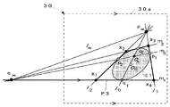
- FIG. 16 is a schematic diagram showing a first modification for obtaining a quadrangle that touches an ellipse.
- FIG. 17 is a schematic diagram illustrating a second modification in which a quadrangle that touches an ellipse is obtained.
- the mobile terminal 10 determines a first contact point and a first tangent line that are horizontal to the image frame and touch the ellipse (step S40). Specifically, as shown in FIG. 16, the control unit 16 of the mobile terminal 10 determines the first contact point q 2 and the first tangent line m 2 that are in contact with the ellipse E1 horizontally on the upper side 30a or the lower side of the image frame 30.
- the image frame 30 is, for example, a rectangular frame that surrounds the entire captured two-dimensional image.
- the mobile terminal 10 calculates a first reference straight line that passes through the first contact point and the center candidate (step S41). More specifically, the control unit 16 calculates the first reference line l 0 which passes through the first contact point q 2 and the center candidate O A.
- the mobile terminal 10 calculates the second contact point and the second tangent line from the first reference straight line and the ellipse (step S42). More specifically, the control unit 16 obtains a more second contacts q 1 intersection of the first reference straight line l 0 and the ellipse E1, calculates a second tangent line m 1 in contact with the ellipse E1 in the second contact q 1.
- the mobile terminal 10 calculates the first vanishing point from the intersection of the first tangent and the second tangent (step S43). Specifically, the control unit 16 calculates the first vanishing point q ⁇ from the intersection of the first tangent m 2 and the second tangent m 1 . Note that steps S44 to S48 are the same as steps S34 to S38, and finally a square P2 as shown in FIG. 16 can be obtained.
- the mobile terminal 10 functions as an example of a first polygon calculating means for calculating a square example of the polygon to the intersection of the straight line and ellipse E1 through the center candidate O A and the contact q 2.
- the mobile terminal 10 functions a point contact and a straight line m 2 and elliptic E1 parallel to any side 30a of the image frame 30 surrounding the target image as an example of a polygon calculating means for the contact q 2.
- the target image when the target image is projectively transformed by the projective transformation from the quadrangle P2 to the square P1 ', a standard image with little image rotation in the circumferential direction can be obtained with respect to the target image. Therefore, it becomes easy for the user to compare the target image with the standard image obtained by conversion, and the image can be easily edited.
- a second modified example of obtaining a square transformation target area in step S40, the first contact q 1 and the first tangential contact with the ellipse E1 horizontally to the upper side 30a or bottom of the image frame 30 m 1 may be determined.
- the shape of the quadrangle P3 is different, the same effect as the first modification can be obtained.
- the mobile terminal 10 functions as an example of a first polygon calculating means for calculating a square example of the polygon to the intersection of the straight line and ellipse E1 through the center candidate O A and contacts q 1.
- the mobile terminal 10 functions as an example of a polygon calculation unit that uses the point where the straight line m 1 parallel to one of the sides 30a of the image frame 30 surrounding the target image 30 and the ellipse E1 contact each other as the contact point q 1 .
- the reference straight line l 0, m 0 is an arbitrary straight line passing through the center candidate O A, and may be a straight line which intersects the main candidate O A to each other, There are various variations.
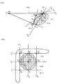
- FIG. 18 is a third modification for obtaining a quadrangle that touches an ellipse, in which (A) is a schematic diagram showing an example of a quadrangle inscribed in the ellipse, and (B) is a schematic diagram showing a state after projective transformation. It is.
- the quadrangle for obtaining the projective transformation matrix P is a quadrangle P4 having apexes of the contacts p 1 , q 1 , p 2 , and q 2 .
- This square P4 is inscribed in the ellipse E1.
- the second polygon for obtaining the projective transformation matrix P has the contact points p 1 ′, q 1 ′, p 2 ′, q 2 ′ as vertices, and a perfect circle E1. It becomes a square P4 inscribed in '.
- the projective transformation matrix calculating means performs the projective transformation of the quadrangle P4 to the square P4 ′ inscribed by the ellipse (the perfect circle E1 ′ in this modification) centered at the point O A ′ where the center candidate O A is projective transformed.
- a projective transformation matrix is calculated.
- the mobile terminal 10 functions as an example of a polygon calculating unit that calculates the first polygon related to the ellipse and the center candidate.
- the mobile terminal 10 functions as an example of a polygon calculation unit that calculates a quadrangle of an example of a first polygon having a contact point at an intersection of a straight line passing through the center candidate and an ellipse.
- the vertices of the quadrangle P4 for obtaining the projective transformation matrix P are easily obtained as the first contact, the second contact, the third contact, and the fourth contact.
- FIG. 19 is a fourth modification for obtaining a quadrangle that touches an ellipse, where (A) is a schematic diagram illustrating an example of a quadrangle that touches an ellipse, and (B) is a schematic diagram illustrating a state after projective transformation. is there.
- the center candidate O A is a case in the vicinity of the edge of the ellipse E1.
- the quadrangle circumscribing the ellipse E1 is the quadrangle P5
- the quadrangle circumscribing the ellipse E1 is the quadrangle P6.
- the first reference line l 0 and the second reference line m 0 is an arbitrary straight line passing through the center candidate O A, and was determined as a straight line which intersects the main candidate O A to each other.
- the quadrangle P5 circumscribing the ellipse E1 at the contacts p 1 , q 1 , p 2 , q 2 does not surround the ellipse E1. Therefore, in the second polygon for obtaining the projective transformation matrix P, the coordinates of x3 ′ corresponding to the vertex x3 are ( ⁇ , ⁇ ), and conceptually, in FIG. The resulting second polygon P5 ′ is obtained. Thus, even when the quadrangle P5 does not surround the ellipse E1, the projective transformation matrix P can be calculated.
- the projective transformation matrix calculating means projects the quadrangle P5 onto the polygon P5 ′ related to the ellipse (the perfect circle E1 ′ in this modification) centered at the point O A ′ where the center candidate O A is projective transformed.
- a projective transformation matrix to be converted is calculated.
- the second polygon for obtaining the projective transformation matrix P is as shown in FIG. p 1 ′, q 1 ′, p 2 ′, and q 2 ′ are the vertices, and a square P6 ′ inscribed in the perfect circle E1 ′ is formed.
- the inscribed rectangle P6 even when the center candidate is close to the edge of the ellipse, it is easy to intuitively think of the second polygon.
- the projective transformation matrix calculating means performs the projective transformation of the quadrangle P6 to the square P6 ′ circumscribing an ellipse (a perfect circle E1 ′ in this modification) centered at the point O A ′ where the center candidate O A is projectively transformed.
- a projective transformation matrix is calculated.
- a triangle or a pentagon may be used as an example of the polygon.
- the coordinates of at least four points may Kimare in connection with the ellipse E1 and center candidates O A.
- a point on a certain side or a point such as the center of gravity, inner center, or outer center inside the triangle may be used as the fourth coordinate.
- the second polygon is, for example, an equiangular polygon such as a regular triangle, a square, a rectangle, or a regular pentagon, or a regular polygon, and is a figure associated with the perfect circle E1 ′ after the projective transformation. It suffices if the matrix P can be calculated. Further, the second polygon is not limited to a regular polygon. An ellipse that is inscribed or circumscribed with respect to the second polygon centered on the point at which the center candidate is projectively transformed is not limited to a perfect circle.
- the image search server 20 side may obtain a standard image that is a converted image displayed in a desired direction from the target image as an image processing apparatus. For example, image data including a target image captured by the mobile terminal 10 is transmitted as a search request image to the image search server 20 side through the network 3. Then, the receiving unit on the image search server 20 side functions as an image acquisition unit, and the image search server 20 converts the image into a standard image, and the image search server 20 searches based on the standard image. Then, the image search server 20 transmits the search result to the mobile terminal 10.
- the target image captured by the digital camera is captured in a personal computer in which a program for functioning the method of the present embodiment is installed and displayed in a desired orientation.
- the standard image which is a converted image may be obtained.
- the processing of the image search server 20 of the image search system 1 may be performed by one server or may be distributed to a plurality of servers.
- a search server may not be provided, and for example, a standard image may be simply obtained, or a process different from a search may be performed using the obtained standard image.
- the target image is not limited to a flower image, and may be, for example, another circular shape, such as a plate, a cup, a CD, a DVD, a clock face, or a road sign.
- the target image is not limited to a flower image, and may be, for example, an elliptical and planar object.
- the present invention is not limited to the above embodiments.
- Each of the embodiments described above is an exemplification, and any configuration that has substantially the same configuration as the technical idea described in the claims of the present invention and has the same operational effects can be used. It is included in the technical scope of the present invention.
Landscapes
- Engineering & Computer Science (AREA)
- Multimedia (AREA)
- Signal Processing (AREA)
- Physics & Mathematics (AREA)
- General Physics & Mathematics (AREA)
- Theoretical Computer Science (AREA)
- Image Processing (AREA)
- Image Analysis (AREA)
- Editing Of Facsimile Originals (AREA)
- Studio Devices (AREA)
Abstract
Description
Ax2+ 2Bxy + Cy2 + 2Dx + 2Ey + F = 0 ・・・(1)
vTc = 1 ・・・(2)
c=-1/F[A,2B,C,2D,2E]T ・・・(3)
c=[x2,xy,y2,x,y]T ・・・(4)
Vc=1 ・・・(5)
∂/∂c∥Vc-1∥2=0 ・・・(6)
c~=(VTV)-1VT=V+1 ・・・(7)
V+は擬似逆行列と呼ばれる。


X=[X1,X2,X3]T ・・・(10)
x = [X1/X3, X2/X3]T ・・・(11)
AX1 2+2BX1X2+CX2 2+2DX1X3+2EX2X3+FX3 2=0 ・・・(12)

XTQX = 0 ・・・(14)
X’ = PX ・・・(15)
X = P’X’ ・・・(16)
Q=PTQ’P ・・・(17)
Q’=P’TQP’ ・・・(18)
15:記憶部
14:撮像部
16:制御部
20:画像検索サーバ
21:制御部
21b:記憶部
22:データベース
30:画像枠
E1:楕円
F1:花の輪郭
F2:花芯の輪郭
OA:中心候補
P1:四角形(第1多角形)
P1’:正方形(第2多角形)
Claims (18)
- 対象画像に対して画像処理を行う画像処理装置であって、
前記対象画像を近似する楕円を算出する楕円算出手段と、
前記対象画像の中心候補を決定する中心候補決定手段と、
前記楕円および前記中心候補に関連した第1多角形を算出する多角形算出手段と、
前記中心候補が射影変換される点を中心とする楕円に関連する第2多角形へ前記第1多角形を射影変換する射影変換行列を算出する射影変換行列算出手段と、
前記対象画像を前記射影変換行列に基づき射影変換して、変換画像を取得する変換画像取得手段と、
を備えたことを特徴とする画像処理装置。 - 請求項1に記載の画像処理装置において、
前記射影変換行列算出手段が、前記中心候補が射影変換される点を中心とする楕円が内接または外接する第2多角形へ前記第1多角形を射影変換する射影変換行列を算出することを特徴とする画像処理装置。 - 前記射影変換行列算出手段における前記中心候補が射影変換される点を中心とする楕円は真円であることを特徴とする請求項1又は2に記載の画像処理装置。
- 請求項1から3のいずれか1項に記載の画像処理装置において、
前記多角形算出手段が、
前記中心候補を通る直線と前記楕円との交点を接点とする前記第1多角形を算出することを特徴とする画像処理装置。 - 請求項4に記載の画像処理装置において、
前記多角形算出手段が、
前記中心候補を通る直線を前記楕円の長軸に平行な直線から求めることを特徴とする画像処理装置。 - 請求項4に記載の画像処理装置において、
前記多角形算出手段が、
前記対象画像を取り囲む画像枠のいずれかの辺に平行な直線と前記楕円とが接する点を前記接点とすることを特徴とする画像処理装置。 - 請求項1から請求項6のいずれか1項に記載の画像処理装置において、
前記多角形算出手段が、前記楕円および前記中心候補に関連した四角形を算出し、
前記射影変換行列算出手段が、前記中心候補が射影変換される点を中心とする楕円に関連する正方形へ前記四角形を射影変換する射影変換行列を算出することを特徴とする画像処理装置。 - 請求項1から請求項7のいずれか1項に記載の画像処理装置において、
前記中心候補決定手段が、
前記対象画像の中から前記中心候補を含む中心候補画像を抽出し、
抽出した前記中心候補画像を楕円近似した楕円の長軸と短軸との交点から前記中心候補を決定することを特徴とする画像処理装置。 - 請求項1から請求項8のいずれか1項に記載の画像処理装置において、
前記対象画像が花画像であって、
前記楕円算出手段が、前記花画像を近似する前記楕円を算出し、
前記中心候補決定手段が、前記花画像の花芯部分から前記花画像の前記中心候補を決定することを特徴とする画像処理装置。 - 請求項1から請求項9のいずれか1項に記載の画像処理装置において、
前記対象画像を含む画像を取得する画像取得手段を更に備えたことを特徴とする画像処理装置。 - 請求項10に記載の画像処理装置において、
前記取得された画像から、前記対象画像を抽出する対象画像抽出手段を更に備えたことを特徴とする画像処理装置。 - 請求項1から請求項11のいずれか1項に記載の画像処理装置において、
前記変換画像に基づき、前記対象画像を特定する情報を検索する検索手段を更に備えたことを特徴とする画像処理装置。 - 請求項12に記載の画像処理装置において、
前記検索手段が、
前記変換画像より画像の特徴量を抽出し、
前記特徴量に基づき、前記対象画像を特定する情報を検索することを特徴とする画像処理装置。 - 請求項1から13のいずれか1項に記載の画像処理装置において、
前記第2多角形が正多角形であることを特徴とする画像処理装置。 - 請求項1から14のいずれか1項に記載の画像処理装置において、
前記対象画像を記憶する記憶手段を更に備えたことを特徴とする画像処理装置。 - 対象画像に対して画像処理を行う画像処理方法であって、
前記対象画像を近似する楕円を算出する楕円算出ステップと、
前記画像処理後における前記対象画像の中心候補を決定する中心候補決定ステップと、
前記楕円および前記中心候補に関連した第1多角形を算出する多角形算出ステップと、
前記中心候補が射影変換される点を中心とする楕円に関連する第2多角形へ前記第1多角形を射影変換する射影変換行列を算出する射影変換行列算出ステップと、
前記対象画像を前記射影変換行列に基づき射影変換して、変換画像を取得する変換画像取得ステップと、
を有することを特徴とする画像処理方法。 - コンピュータを、
画像処理の対象画像を近似する楕円を算出する楕円算出手段、
前記画像処理後における前記対象画像の中心候補を決定する中心候補決定手段、
前記楕円および前記中心候補に関連した第1多角形を算出する多角形算出手段、
前記中心候補が射影変換される点を中心とする楕円に関連する第2多角形へ前記第1多角形を射影変換する射影変換行列を算出する射影変換行列算出手段、および、
前記対象画像を前記射影変換行列に基づき射影変換して、変換画像を取得する変換画像取得手段として機能させることを特徴とする画像処理プログラム。 - コンピュータを、
画像処理の対象画像を近似する楕円を算出する楕円算出手段、
前記画像処理後における前記対象画像の中心候補を決定する中心候補決定手段、
前記楕円および前記中心候補に関連した第1多角形を算出する多角形算出手段、
前記中心候補が射影変換される点を中心とする楕円に関連する第2多角形へ前記第1多角形を射影変換する射影変換行列を算出する射影変換行列算出手段、および、
前記対象画像を前記射影変換行列に基づき射影変換して、変換画像を取得する変換画像取得手段として機能させることを特徴とする画像処理プログラムを記録したコンピュータ読み取り可能な記録媒体。
Priority Applications (6)
| Application Number | Priority Date | Filing Date | Title |
|---|---|---|---|
| KR1020127012887A KR101379066B1 (ko) | 2009-10-20 | 2010-10-18 | 화상 처리 장치, 화상 처리 방법, 및, 기록 매체 |
| EP10824895.6A EP2477152B1 (en) | 2009-10-20 | 2010-10-18 | Image processing device, image processing method, image processing program, and recording medium |
| US13/502,972 US8660309B2 (en) | 2009-10-20 | 2010-10-18 | Image processing apparatus, image processing method, image processing program and recording medium |
| CN201080053867.3A CN102656605B (zh) | 2009-10-20 | 2010-10-18 | 图像处理装置、图像处理方法 |
| CA2776881A CA2776881C (en) | 2009-10-20 | 2010-10-18 | Image processing device, image processing method, image processing program, and recording medium |
| ES10824895.6T ES2694762T3 (es) | 2009-10-20 | 2010-10-18 | Dispositivo de procesamiento de imágenes, procedimiento de procesamiento de imágenes, programa de procesamiento de imágenes y medio de grabación |
Applications Claiming Priority (2)
| Application Number | Priority Date | Filing Date | Title |
|---|---|---|---|
| JP2009-241233 | 2009-10-20 | ||
| JP2009241233A JP5075182B2 (ja) | 2009-10-20 | 2009-10-20 | 画像処理装置、画像処理方法、および、画像処理プログラム |
Publications (1)
| Publication Number | Publication Date |
|---|---|
| WO2011049046A1 true WO2011049046A1 (ja) | 2011-04-28 |
Family
ID=43900272
Family Applications (1)
| Application Number | Title | Priority Date | Filing Date |
|---|---|---|---|
| PCT/JP2010/068281 Ceased WO2011049046A1 (ja) | 2009-10-20 | 2010-10-18 | 画像処理装置、画像処理方法、画像処理プログラム、および、記録媒体 |
Country Status (9)
| Country | Link |
|---|---|
| US (1) | US8660309B2 (ja) |
| EP (1) | EP2477152B1 (ja) |
| JP (1) | JP5075182B2 (ja) |
| KR (1) | KR101379066B1 (ja) |
| CN (1) | CN102656605B (ja) |
| CA (1) | CA2776881C (ja) |
| ES (1) | ES2694762T3 (ja) |
| TW (1) | TWI434567B (ja) |
| WO (1) | WO2011049046A1 (ja) |
Cited By (1)
| Publication number | Priority date | Publication date | Assignee | Title |
|---|---|---|---|---|
| CN109003327A (zh) * | 2018-06-29 | 2018-12-14 | 平安科技(深圳)有限公司 | 图像处理方法、装置、计算机设备及存储介质 |
Families Citing this family (27)
| Publication number | Priority date | Publication date | Assignee | Title |
|---|---|---|---|---|
| TWI476730B (zh) * | 2012-10-31 | 2015-03-11 | Vivotek Inc | 數位影像的反扭曲處理方法 |
| CN106296578B (zh) * | 2015-05-29 | 2020-04-28 | 阿里巴巴集团控股有限公司 | 一种图像处理方法及装置 |
| US11568627B2 (en) | 2015-11-18 | 2023-01-31 | Adobe Inc. | Utilizing interactive deep learning to select objects in digital visual media |
| US10192129B2 (en) * | 2015-11-18 | 2019-01-29 | Adobe Systems Incorporated | Utilizing interactive deep learning to select objects in digital visual media |
| CN107767326B (zh) * | 2017-09-28 | 2021-11-02 | 北京奇虎科技有限公司 | 图像中对象变换处理方法、装置及计算设备 |
| CN108038880B (zh) * | 2017-12-20 | 2019-12-13 | 百度在线网络技术(北京)有限公司 | 用于处理图像的方法和装置 |
| US10719937B2 (en) * | 2017-12-22 | 2020-07-21 | ABYY Production LLC | Automated detection and trimming of an ambiguous contour of a document in an image |
| WO2019181337A1 (ja) | 2018-03-23 | 2019-09-26 | 株式会社 東芝 | 読取システム、読取方法、及び記憶媒体 |
| JP6730379B2 (ja) * | 2018-03-23 | 2020-07-29 | 株式会社東芝 | 読取システム、読取方法、プログラム、及び記憶媒体 |
| JP6609345B2 (ja) | 2018-04-27 | 2019-11-20 | 株式会社東芝 | 読取システム、読取方法、プログラム、及び記憶媒体 |
| US11244195B2 (en) | 2018-05-01 | 2022-02-08 | Adobe Inc. | Iteratively applying neural networks to automatically identify pixels of salient objects portrayed in digital images |
| CN110650239B (zh) * | 2018-06-26 | 2021-03-16 | 百度在线网络技术(北京)有限公司 | 图像处理方法、装置、计算机设备及存储介质 |
| JP6818002B2 (ja) | 2018-12-12 | 2021-01-20 | 株式会社東芝 | 読取支援システム、移動体、読取支援方法、プログラム、及び記憶媒体 |
| US11282208B2 (en) | 2018-12-24 | 2022-03-22 | Adobe Inc. | Identifying target objects using scale-diverse segmentation neural networks |
| JP6763060B1 (ja) | 2019-05-27 | 2020-09-30 | 株式会社東芝 | 読取システム、移動体、読取方法、プログラム、及び記憶媒体 |
| CN110659370B (zh) * | 2019-08-12 | 2024-04-02 | 深圳市华付信息技术有限公司 | 一种高效数据标注方法 |
| CN113327863B (zh) * | 2020-02-28 | 2022-06-21 | 芯恩(青岛)集成电路有限公司 | 半导体工艺方法 |
| CN113469872B (zh) * | 2020-03-31 | 2024-01-19 | 广东博智林机器人有限公司 | 一种区域显示方法、装置、设备及存储介质 |
| US11335004B2 (en) | 2020-08-07 | 2022-05-17 | Adobe Inc. | Generating refined segmentation masks based on uncertain pixels |
| JP2022036839A (ja) * | 2020-08-24 | 2022-03-08 | セイコーエプソン株式会社 | 画像処理装置、画像処理方法および画像処理プログラム |
| US11676279B2 (en) | 2020-12-18 | 2023-06-13 | Adobe Inc. | Utilizing a segmentation neural network to process initial object segmentations and object user indicators within a digital image to generate improved object segmentations |
| CN113763439B (zh) * | 2021-02-07 | 2025-03-18 | 北京沃东天骏信息技术有限公司 | 图像处理方法和装置 |
| US11875510B2 (en) | 2021-03-12 | 2024-01-16 | Adobe Inc. | Generating refined segmentations masks via meticulous object segmentation |
| US12020400B2 (en) | 2021-10-23 | 2024-06-25 | Adobe Inc. | Upsampling and refining segmentation masks |
| CN115272448B (zh) * | 2022-07-25 | 2026-03-06 | 武汉理工大学 | 一种视觉测量中离焦同心圆图像实际中心确定方法及装置 |
| WO2024089763A1 (ja) * | 2022-10-25 | 2024-05-02 | 日本電信電話株式会社 | 矩形領域推定装置、矩形領域推定方法及びプログラム |
| CN118364838B (zh) * | 2024-05-06 | 2026-04-03 | 招商银行股份有限公司 | 图片变换方法、装置、设备以及存储介质 |
Citations (7)
| Publication number | Priority date | Publication date | Assignee | Title |
|---|---|---|---|---|
| JPH0290378A (ja) * | 1988-09-28 | 1990-03-29 | Agency Of Ind Science & Technol | 円の3次元計測方法 |
| JP2002203242A (ja) * | 2000-12-28 | 2002-07-19 | Japan Science & Technology Corp | 植物認識システム |
| JP2005122320A (ja) | 2003-10-14 | 2005-05-12 | Casio Comput Co Ltd | 撮影装置、その画像処理方法及びプログラム |
| JP2006277293A (ja) * | 2005-03-29 | 2006-10-12 | Dainippon Printing Co Ltd | 回転体の三次元情報復元装置 |
| JP2007200020A (ja) * | 2006-01-26 | 2007-08-09 | Nikon Corp | 対象物認識システム |
| JP2007251720A (ja) * | 2006-03-17 | 2007-09-27 | Nikon Corp | 対象物認識システム |
| JP2007251700A (ja) * | 2006-03-17 | 2007-09-27 | Casio Comput Co Ltd | デジタルカメラ及び画像処理プログラム |
Family Cites Families (3)
| Publication number | Priority date | Publication date | Assignee | Title |
|---|---|---|---|---|
| GB2397423B (en) * | 2001-09-17 | 2005-06-01 | Ca Minister Agriculture & Food | A method and apparatus for identifying and quantifying characteristics of seeds and other small objects |
| JP4033198B2 (ja) * | 2004-02-27 | 2008-01-16 | カシオ計算機株式会社 | 画像処理装置、画像投影装置、画像処理方法及びプログラム |
| KR100947002B1 (ko) * | 2005-08-25 | 2010-03-11 | 가부시키가이샤 리코 | 화상 처리 방법 및 장치, 디지털 카메라, 및 화상 처리프로그램을 기록한 기록 매체 |
-
2009
- 2009-10-20 JP JP2009241233A patent/JP5075182B2/ja active Active
-
2010
- 2010-10-18 CN CN201080053867.3A patent/CN102656605B/zh active Active
- 2010-10-18 ES ES10824895.6T patent/ES2694762T3/es active Active
- 2010-10-18 US US13/502,972 patent/US8660309B2/en active Active
- 2010-10-18 KR KR1020127012887A patent/KR101379066B1/ko active Active
- 2010-10-18 CA CA2776881A patent/CA2776881C/en active Active
- 2010-10-18 WO PCT/JP2010/068281 patent/WO2011049046A1/ja not_active Ceased
- 2010-10-18 EP EP10824895.6A patent/EP2477152B1/en active Active
- 2010-10-20 TW TW099135750A patent/TWI434567B/zh active
Patent Citations (7)
| Publication number | Priority date | Publication date | Assignee | Title |
|---|---|---|---|---|
| JPH0290378A (ja) * | 1988-09-28 | 1990-03-29 | Agency Of Ind Science & Technol | 円の3次元計測方法 |
| JP2002203242A (ja) * | 2000-12-28 | 2002-07-19 | Japan Science & Technology Corp | 植物認識システム |
| JP2005122320A (ja) | 2003-10-14 | 2005-05-12 | Casio Comput Co Ltd | 撮影装置、その画像処理方法及びプログラム |
| JP2006277293A (ja) * | 2005-03-29 | 2006-10-12 | Dainippon Printing Co Ltd | 回転体の三次元情報復元装置 |
| JP2007200020A (ja) * | 2006-01-26 | 2007-08-09 | Nikon Corp | 対象物認識システム |
| JP2007251720A (ja) * | 2006-03-17 | 2007-09-27 | Nikon Corp | 対象物認識システム |
| JP2007251700A (ja) * | 2006-03-17 | 2007-09-27 | Casio Comput Co Ltd | デジタルカメラ及び画像処理プログラム |
Cited By (1)
| Publication number | Priority date | Publication date | Assignee | Title |
|---|---|---|---|---|
| CN109003327A (zh) * | 2018-06-29 | 2018-12-14 | 平安科技(深圳)有限公司 | 图像处理方法、装置、计算机设备及存储介质 |
Also Published As
| Publication number | Publication date |
|---|---|
| EP2477152B1 (en) | 2018-10-17 |
| US8660309B2 (en) | 2014-02-25 |
| CN102656605A (zh) | 2012-09-05 |
| CA2776881A1 (en) | 2011-04-28 |
| KR20120083486A (ko) | 2012-07-25 |
| US20120201423A1 (en) | 2012-08-09 |
| TWI434567B (zh) | 2014-04-11 |
| TW201143352A (en) | 2011-12-01 |
| EP2477152A1 (en) | 2012-07-18 |
| KR101379066B1 (ko) | 2014-03-28 |
| CA2776881C (en) | 2016-01-05 |
| ES2694762T3 (es) | 2018-12-27 |
| CN102656605B (zh) | 2015-12-16 |
| JP5075182B2 (ja) | 2012-11-14 |
| EP2477152A4 (en) | 2014-01-15 |
| JP2011090374A (ja) | 2011-05-06 |
Similar Documents
| Publication | Publication Date | Title |
|---|---|---|
| JP5075182B2 (ja) | 画像処理装置、画像処理方法、および、画像処理プログラム | |
| CN110568447B (zh) | 视觉定位的方法、装置及计算机可读介质 | |
| EP2328125B1 (en) | Image splicing method and device | |
| JP7675288B2 (ja) | 撮影測定方法、装置、機器及び記憶媒体 | |
| WO2018214365A1 (zh) | 图像校正方法、装置、设备、系统及摄像设备和显示设备 | |
| CN107690673A (zh) | 图像处理方法、装置及服务器 | |
| JP2014071850A (ja) | 画像処理装置、端末装置、画像処理方法、およびプログラム | |
| JP2011239361A (ja) | 繰り返し撮影用arナビゲーション及び差異抽出のシステム、方法及びプログラム | |
| CN115641401A (zh) | 一种三维实景模型的构建方法及相关装置 | |
| CN111693025B (zh) | 一种遥感影像数据生成方法、系统及设备 | |
| JP2017208619A (ja) | 画像処理装置、画像処理方法、プログラム及び撮像システム | |
| KR101574636B1 (ko) | 면형방식 디지털 항공카메라로 촬영한 시계열 항공사진을 입체시하여 좌표를 연동하고 변화지역을 판독하는 시스템 | |
| US10482571B2 (en) | Dual fisheye, hemispherical image projection and stitching method, device and computer-readable medium | |
| JP6486603B2 (ja) | 画像処理装置 | |
| KR20110082903A (ko) | 항공사진의 정사보정 및 최적화된 정사영상 제작 방법 | |
| CN112270702A (zh) | 体积测量方法及装置、计算机可读介质和电子设备 | |
| JP2016212784A (ja) | 画像処理装置、画像処理方法 | |
| JP2014164483A (ja) | データベース生成装置、カメラ姿勢推定装置、データベース生成方法、カメラ姿勢推定方法、およびプログラム | |
| CN114066731B (zh) | 生成全景图的方法、装置、电子设备及存储介质 | |
| JP5216703B2 (ja) | 映像表示システム、及び、映像表示方法 | |
| KR101598399B1 (ko) | 로드뷰 사진이미지의 좌표정보를 이용한 자동 이미지 합성 시스템 | |
| JP6714819B2 (ja) | 画像表示システム、情報処理装置、画像表示方法及び画像表示プログラム | |
| CN113012160A (zh) | 图像处理方法、装置、终端设备及计算机可读存储介质 | |
| JP6625654B2 (ja) | 投影装置、投影方法、および、プログラム | |
| KR100953737B1 (ko) | 이미지 매칭을 이용한 맨홀 도화 시스템 |
Legal Events
| Date | Code | Title | Description |
|---|---|---|---|
| WWE | Wipo information: entry into national phase |
Ref document number: 201080053867.3 Country of ref document: CN |
|
| 121 | Ep: the epo has been informed by wipo that ep was designated in this application |
Ref document number: 10824895 Country of ref document: EP Kind code of ref document: A1 |
|
| WWE | Wipo information: entry into national phase |
Ref document number: 2776881 Country of ref document: CA |
|
| WWE | Wipo information: entry into national phase |
Ref document number: 2010824895 Country of ref document: EP |
|
| WWE | Wipo information: entry into national phase |
Ref document number: 13502972 Country of ref document: US |
|
| WWE | Wipo information: entry into national phase |
Ref document number: 1201001767 Country of ref document: TH |
|
| WWE | Wipo information: entry into national phase |
Ref document number: 4287/CHENP/2012 Country of ref document: IN |
|
| ENP | Entry into the national phase |
Ref document number: 20127012887 Country of ref document: KR Kind code of ref document: A |