WO2011049183A1 - ターボコンパウンドシステムおよびその運転方法 - Google Patents
ターボコンパウンドシステムおよびその運転方法 Download PDFInfo
- Publication number
- WO2011049183A1 WO2011049183A1 PCT/JP2010/068634 JP2010068634W WO2011049183A1 WO 2011049183 A1 WO2011049183 A1 WO 2011049183A1 JP 2010068634 W JP2010068634 W JP 2010068634W WO 2011049183 A1 WO2011049183 A1 WO 2011049183A1
- Authority
- WO
- WIPO (PCT)
- Prior art keywords
- turbine
- power
- exhaust
- exhaust gas
- output
- Prior art date
- Legal status (The legal status is an assumption and is not a legal conclusion. Google has not performed a legal analysis and makes no representation as to the accuracy of the status listed.)
- Ceased
Links
Images

Classifications
-
- F—MECHANICAL ENGINEERING; LIGHTING; HEATING; WEAPONS; BLASTING
- F01—MACHINES OR ENGINES IN GENERAL; ENGINE PLANTS IN GENERAL; STEAM ENGINES
- F01K—STEAM ENGINE PLANTS; STEAM ACCUMULATORS; ENGINE PLANTS NOT OTHERWISE PROVIDED FOR; ENGINES USING SPECIAL WORKING FLUIDS OR CYCLES
- F01K23/00—Plants characterised by more than one engine delivering power external to the plant, the engines being driven by different fluids
- F01K23/02—Plants characterised by more than one engine delivering power external to the plant, the engines being driven by different fluids the engine cycles being thermally coupled
- F01K23/06—Plants characterised by more than one engine delivering power external to the plant, the engines being driven by different fluids the engine cycles being thermally coupled combustion heat from one cycle heating the fluid in another cycle
- F01K23/10—Plants characterised by more than one engine delivering power external to the plant, the engines being driven by different fluids the engine cycles being thermally coupled combustion heat from one cycle heating the fluid in another cycle with exhaust fluid of one cycle heating the fluid in another cycle
-
- F—MECHANICAL ENGINEERING; LIGHTING; HEATING; WEAPONS; BLASTING
- F01—MACHINES OR ENGINES IN GENERAL; ENGINE PLANTS IN GENERAL; STEAM ENGINES
- F01D—NON-POSITIVE DISPLACEMENT MACHINES OR ENGINES, e.g. STEAM TURBINES
- F01D15/00—Adaptations of machines or engines for special use; Combinations of engines with devices driven thereby
- F01D15/02—Adaptations for driving vehicles, e.g. locomotives
- F01D15/04—Adaptations for driving vehicles, e.g. locomotives the vehicles being waterborne vessels
-
- F—MECHANICAL ENGINEERING; LIGHTING; HEATING; WEAPONS; BLASTING
- F01—MACHINES OR ENGINES IN GENERAL; ENGINE PLANTS IN GENERAL; STEAM ENGINES
- F01D—NON-POSITIVE DISPLACEMENT MACHINES OR ENGINES, e.g. STEAM TURBINES
- F01D15/00—Adaptations of machines or engines for special use; Combinations of engines with devices driven thereby
- F01D15/10—Adaptations for driving, or combinations with, electric generators
-
- F—MECHANICAL ENGINEERING; LIGHTING; HEATING; WEAPONS; BLASTING
- F01—MACHINES OR ENGINES IN GENERAL; ENGINE PLANTS IN GENERAL; STEAM ENGINES
- F01K—STEAM ENGINE PLANTS; STEAM ACCUMULATORS; ENGINE PLANTS NOT OTHERWISE PROVIDED FOR; ENGINES USING SPECIAL WORKING FLUIDS OR CYCLES
- F01K13/00—General layout or general methods of operation of complete plants
- F01K13/02—Controlling, e.g. stopping or starting
-
- F—MECHANICAL ENGINEERING; LIGHTING; HEATING; WEAPONS; BLASTING
- F01—MACHINES OR ENGINES IN GENERAL; ENGINE PLANTS IN GENERAL; STEAM ENGINES
- F01K—STEAM ENGINE PLANTS; STEAM ACCUMULATORS; ENGINE PLANTS NOT OTHERWISE PROVIDED FOR; ENGINES USING SPECIAL WORKING FLUIDS OR CYCLES
- F01K15/00—Adaptations of plants for special use
- F01K15/02—Adaptations of plants for special use for driving vehicles, e.g. locomotives
- F01K15/04—Adaptations of plants for special use for driving vehicles, e.g. locomotives the vehicles being waterborne vessels
-
- F—MECHANICAL ENGINEERING; LIGHTING; HEATING; WEAPONS; BLASTING
- F01—MACHINES OR ENGINES IN GENERAL; ENGINE PLANTS IN GENERAL; STEAM ENGINES
- F01K—STEAM ENGINE PLANTS; STEAM ACCUMULATORS; ENGINE PLANTS NOT OTHERWISE PROVIDED FOR; ENGINES USING SPECIAL WORKING FLUIDS OR CYCLES
- F01K23/00—Plants characterised by more than one engine delivering power external to the plant, the engines being driven by different fluids
- F01K23/02—Plants characterised by more than one engine delivering power external to the plant, the engines being driven by different fluids the engine cycles being thermally coupled
- F01K23/06—Plants characterised by more than one engine delivering power external to the plant, the engines being driven by different fluids the engine cycles being thermally coupled combustion heat from one cycle heating the fluid in another cycle
- F01K23/065—Plants characterised by more than one engine delivering power external to the plant, the engines being driven by different fluids the engine cycles being thermally coupled combustion heat from one cycle heating the fluid in another cycle the combustion taking place in an internal combustion piston engine, e.g. a diesel engine
-
- F—MECHANICAL ENGINEERING; LIGHTING; HEATING; WEAPONS; BLASTING
- F01—MACHINES OR ENGINES IN GENERAL; ENGINE PLANTS IN GENERAL; STEAM ENGINES
- F01K—STEAM ENGINE PLANTS; STEAM ACCUMULATORS; ENGINE PLANTS NOT OTHERWISE PROVIDED FOR; ENGINES USING SPECIAL WORKING FLUIDS OR CYCLES
- F01K23/00—Plants characterised by more than one engine delivering power external to the plant, the engines being driven by different fluids
- F01K23/12—Plants characterised by more than one engine delivering power external to the plant, the engines being driven by different fluids the engines being mechanically coupled
- F01K23/14—Plants characterised by more than one engine delivering power external to the plant, the engines being driven by different fluids the engines being mechanically coupled including at least one combustion engine
-
- F—MECHANICAL ENGINEERING; LIGHTING; HEATING; WEAPONS; BLASTING
- F01—MACHINES OR ENGINES IN GENERAL; ENGINE PLANTS IN GENERAL; STEAM ENGINES
- F01N—GAS-FLOW SILENCERS OR EXHAUST APPARATUS FOR MACHINES OR ENGINES IN GENERAL; GAS-FLOW SILENCERS OR EXHAUST APPARATUS FOR INTERNAL-COMBUSTION ENGINES
- F01N5/00—Exhaust or silencing apparatus combined or associated with devices profiting by exhaust energy
- F01N5/02—Exhaust or silencing apparatus combined or associated with devices profiting by exhaust energy the devices using heat
-
- F—MECHANICAL ENGINEERING; LIGHTING; HEATING; WEAPONS; BLASTING
- F01—MACHINES OR ENGINES IN GENERAL; ENGINE PLANTS IN GENERAL; STEAM ENGINES
- F01N—GAS-FLOW SILENCERS OR EXHAUST APPARATUS FOR MACHINES OR ENGINES IN GENERAL; GAS-FLOW SILENCERS OR EXHAUST APPARATUS FOR INTERNAL-COMBUSTION ENGINES
- F01N5/00—Exhaust or silencing apparatus combined or associated with devices profiting by exhaust energy
- F01N5/04—Exhaust or silencing apparatus combined or associated with devices profiting by exhaust energy the devices using kinetic energy
-
- F—MECHANICAL ENGINEERING; LIGHTING; HEATING; WEAPONS; BLASTING
- F02—COMBUSTION ENGINES; HOT-GAS OR COMBUSTION-PRODUCT ENGINE PLANTS
- F02B—INTERNAL-COMBUSTION PISTON ENGINES; COMBUSTION ENGINES IN GENERAL
- F02B37/00—Engines characterised by provision of pumps driven at least for part of the time by exhaust
- F02B37/001—Engines characterised by provision of pumps driven at least for part of the time by exhaust using exhaust drives arranged in parallel
- F02B37/002—Engines characterised by provision of pumps driven at least for part of the time by exhaust using exhaust drives arranged in parallel the exhaust supply to one of the exhaust drives can be interrupted
-
- F—MECHANICAL ENGINEERING; LIGHTING; HEATING; WEAPONS; BLASTING
- F02—COMBUSTION ENGINES; HOT-GAS OR COMBUSTION-PRODUCT ENGINE PLANTS
- F02B—INTERNAL-COMBUSTION PISTON ENGINES; COMBUSTION ENGINES IN GENERAL
- F02B37/00—Engines characterised by provision of pumps driven at least for part of the time by exhaust
- F02B37/007—Engines characterised by provision of pumps driven at least for part of the time by exhaust with exhaust-driven pumps arranged in parallel, e.g. at least one pump supplying alternatively
-
- F—MECHANICAL ENGINEERING; LIGHTING; HEATING; WEAPONS; BLASTING
- F02—COMBUSTION ENGINES; HOT-GAS OR COMBUSTION-PRODUCT ENGINE PLANTS
- F02B—INTERNAL-COMBUSTION PISTON ENGINES; COMBUSTION ENGINES IN GENERAL
- F02B41/00—Engines characterised by special means for improving conversion of heat or pressure energy into mechanical power
- F02B41/02—Engines with prolonged expansion
- F02B41/10—Engines with prolonged expansion in exhaust turbines
-
- F—MECHANICAL ENGINEERING; LIGHTING; HEATING; WEAPONS; BLASTING
- F02—COMBUSTION ENGINES; HOT-GAS OR COMBUSTION-PRODUCT ENGINE PLANTS
- F02C—GAS-TURBINE PLANTS; AIR INTAKES FOR JET-PROPULSION PLANTS; CONTROLLING FUEL SUPPLY IN AIR-BREATHING JET-PROPULSION PLANTS
- F02C6/00—Plural gas-turbine plants; Combinations of gas-turbine plants with other apparatus; Adaptations of gas-turbine plants for special use
- F02C6/04—Gas-turbine plants providing heated or pressurised working fluid for other apparatus, e.g. without mechanical power output
- F02C6/10—Gas-turbine plants providing heated or pressurised working fluid for other apparatus, e.g. without mechanical power output supplying working fluid to a user, e.g. a chemical process, which returns working fluid to a turbine of the plant
- F02C6/12—Turbochargers, i.e. plants for augmenting mechanical power output of internal-combustion piston engines by increase of charge pressure
-
- F—MECHANICAL ENGINEERING; LIGHTING; HEATING; WEAPONS; BLASTING
- F02—COMBUSTION ENGINES; HOT-GAS OR COMBUSTION-PRODUCT ENGINE PLANTS
- F02D—CONTROLLING COMBUSTION ENGINES
- F02D23/00—Controlling engines characterised by their being supercharged
-
- F—MECHANICAL ENGINEERING; LIGHTING; HEATING; WEAPONS; BLASTING
- F02—COMBUSTION ENGINES; HOT-GAS OR COMBUSTION-PRODUCT ENGINE PLANTS
- F02D—CONTROLLING COMBUSTION ENGINES
- F02D29/00—Controlling engines, such controlling being peculiar to the devices driven thereby, the devices being other than parts or accessories essential to engine operation, e.g. controlling of engines by signals external thereto
- F02D29/06—Controlling engines, such controlling being peculiar to the devices driven thereby, the devices being other than parts or accessories essential to engine operation, e.g. controlling of engines by signals external thereto peculiar to engines driving electric generators
-
- F—MECHANICAL ENGINEERING; LIGHTING; HEATING; WEAPONS; BLASTING
- F02—COMBUSTION ENGINES; HOT-GAS OR COMBUSTION-PRODUCT ENGINE PLANTS
- F02D—CONTROLLING COMBUSTION ENGINES
- F02D41/00—Electrical control of supply of combustible mixture or its constituents
- F02D41/0002—Controlling intake air
- F02D41/0007—Controlling intake air for control of turbo-charged or super-charged engines
-
- F—MECHANICAL ENGINEERING; LIGHTING; HEATING; WEAPONS; BLASTING
- F02—COMBUSTION ENGINES; HOT-GAS OR COMBUSTION-PRODUCT ENGINE PLANTS
- F02D—CONTROLLING COMBUSTION ENGINES
- F02D41/00—Electrical control of supply of combustible mixture or its constituents
- F02D41/02—Circuit arrangements for generating control signals
- F02D41/021—Introducing corrections for particular conditions exterior to the engine
-
- F—MECHANICAL ENGINEERING; LIGHTING; HEATING; WEAPONS; BLASTING
- F02—COMBUSTION ENGINES; HOT-GAS OR COMBUSTION-PRODUCT ENGINE PLANTS
- F02B—INTERNAL-COMBUSTION PISTON ENGINES; COMBUSTION ENGINES IN GENERAL
- F02B29/00—Engines characterised by provision for charging or scavenging not provided for in groups F02B25/00, F02B27/00 or F02B33/00 - F02B39/00; Details thereof
- F02B29/04—Cooling of air intake supply
- F02B29/0406—Layout of the intake air cooling or coolant circuit
- F02B29/0412—Multiple heat exchangers arranged in parallel or in series
-
- F—MECHANICAL ENGINEERING; LIGHTING; HEATING; WEAPONS; BLASTING
- F05—INDEXING SCHEMES RELATING TO ENGINES OR PUMPS IN VARIOUS SUBCLASSES OF CLASSES F01-F04
- F05D—INDEXING SCHEME FOR ASPECTS RELATING TO NON-POSITIVE-DISPLACEMENT MACHINES OR ENGINES, GAS-TURBINES OR JET-PROPULSION PLANTS
- F05D2240/00—Components
- F05D2240/40—Use of a multiplicity of similar components
-
- Y—GENERAL TAGGING OF NEW TECHNOLOGICAL DEVELOPMENTS; GENERAL TAGGING OF CROSS-SECTIONAL TECHNOLOGIES SPANNING OVER SEVERAL SECTIONS OF THE IPC; TECHNICAL SUBJECTS COVERED BY FORMER USPC CROSS-REFERENCE ART COLLECTIONS [XRACs] AND DIGESTS
- Y02—TECHNOLOGIES OR APPLICATIONS FOR MITIGATION OR ADAPTATION AGAINST CLIMATE CHANGE
- Y02T—CLIMATE CHANGE MITIGATION TECHNOLOGIES RELATED TO TRANSPORTATION
- Y02T10/00—Road transport of goods or passengers
- Y02T10/10—Internal combustion engine [ICE] based vehicles
- Y02T10/12—Improving ICE efficiencies
Definitions
- the present invention relates to a turbo compound system that recovers exhaust heat energy of exhaust gas (combustion gas) discharged from an engine main body constituting a marine diesel engine, an onshore generator diesel engine, and the like, and an operation method thereof.
- exhaust gas combustion gas
- a turbo compound system that further includes a power turbine driven by exhaust gas from a diesel engine and a steam turbine is configured, and exhaust gas energy is recovered as power generation output to further save energy Attempts have been made to improve.
- the present invention has been made in view of such circumstances, and an object of the present invention is to provide a turbo compound system which is excellent in energy saving and improved in engine output or efficiency.
- the turbo compound system and the operation method thereof according to the present invention employ the following means. That is, the turbo compound system according to the first aspect of the present invention is extracted from a plurality of exhaust turbine superchargers driven by exhaust gas guided from the engine body and upstream of these exhaust turbine superchargers.
- the control unit is an engine of the engine body.
- the exhaust turbine superchargers When the engine load of the engine body is in a low load region that is a predetermined value or less, at least one of the exhaust turbine superchargers is stopped. Since at least one exhaust turbine supercharger is stopped, the flow rate of the exhaust gas flowing into the other exhaust turbine supercharger is increased by that amount and supplied from the other exhaust turbine supercharger to the engine body.
- the scavenging pressure (the pressure of the supercharged air (outside air)) will increase.
- the power turbine can be started and the minimum scavenging pressure is obtained so that the exhaust heat can be recovered. Therefore, the exhaust heat energy from the engine body can be effectively recovered as power (power generation amount). Can save energy.
- the onboard power demand is less than the maximum possible power output of the turbo compound system
- the amount of exhaust gas extracted from the engine body is reduced to reduce the output of the power turbine, so the exhaust gas is reduced by reducing the amount of exhaust gas extracted.
- the scavenging pressure can be increased by increasing the amount of exhaust gas flowing to the turbine supercharger. Thereby, even if the engine body is lightly loaded, the scavenging pressure can be increased to improve the efficiency of the engine body. Even if the output of the power turbine is reduced as described above, power can be generated by the steam turbine that recovers heat by the exhaust gas boiler, so that the necessary power output can be ensured.
- the control unit when the demand power is reduced, the control unit is configured to compensate for the difference between the output of the steam turbine and the demand power. Reduce output.
- the output of the power turbine is reduced so as to compensate for the difference between the output of the steam turbine and the demand power.
- the scavenging pressure is increased preferentially due to the decrease in the output of the power turbine, so that the efficiency of the engine body can be improved.
- the power turbine output is reduced so as to compensate for the difference between the steam turbine output and the demand power, and the power turbine is given priority over the steam turbine. An excessive reduction in turbine output can be reduced as much as possible.
- the turbo compound system operating method includes a plurality of exhaust turbine superchargers driven by exhaust gas guided from an engine main body, and air is extracted from the upstream side of these exhaust turbine superchargers.
- a power turbine driven by the exhaust gas a steam turbine connected to a rotating shaft of the power turbine and driven by steam generated by an exhaust gas boiler using the exhaust gas of the engine body, the power turbine and the steam turbine
- the control unit includes: When the engine load of the engine body is less than a predetermined value, the exhaust turbine supercharging It stops the at least one of, when the ship power demand is less than the maximum power output capable of turbocompound system, reduces the amount of exhaust gas to be bled to reduce the output of the power turbine from the engine body.
- the exhaust turbine superchargers When the engine load of the engine body is in a low load region that is a predetermined value or less, at least one of the exhaust turbine superchargers is stopped. Since at least one exhaust turbine supercharger is stopped, the flow rate of the exhaust gas flowing into the other exhaust turbine supercharger is increased by that amount and supplied from the other exhaust turbine supercharger to the engine body.
- the scavenging pressure (the pressure of the supercharged air (outside air)) will increase.
- the power turbine can be started and the minimum scavenging pressure is obtained so that the exhaust heat can be recovered. Therefore, the exhaust heat energy from the engine body can be effectively recovered as power (power generation amount). Can save energy.
- the onboard power demand is less than the maximum possible power output of the turbo compound system
- the amount of exhaust gas extracted from the engine body is reduced to reduce the output of the power turbine, so the exhaust gas is reduced by reducing the amount of exhaust gas extracted.
- the scavenging pressure can be increased by increasing the amount of exhaust gas flowing to the turbine supercharger. Thereby, even if the engine body is lightly loaded, the scavenging pressure can be increased to improve the efficiency of the engine body. Even if the output of the power turbine is reduced as described above, power can be generated by the steam turbine that recovers heat by the exhaust gas boiler, so that the necessary power output can be ensured.
- the turbo compound system and the operating method of the present invention the following operational effects can be obtained.
- stop at least one of the exhaust turbine superchargers and further reduce the amount of exhaust gas extracted from the engine body to reduce the power turbine output. Since the scavenging pressure is increased, the operating region of the power turbine can be increased, and not only energy saving can be improved, but also the efficiency of the engine body can be improved.
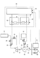
- a marine diesel engine 1 includes a diesel engine main body (for example, a low-speed two-cycle diesel engine) 2, a first exhaust turbine supercharger (main exhaust turbine supercharger) 3, and the like. , A second exhaust turbine supercharger (sub-exhaust turbine supercharger) 4, a power turbine 5, a steam turbine 10, and a turbine generator 25 connected to the power turbine 5 and the steam turbine 10. ing.
- a screw propeller (not shown) is directly or indirectly connected to a crankshaft (not shown) constituting the diesel engine main body (hereinafter referred to as “engine main body”) 2 via a propeller shaft (not shown). It is attached.
- the engine body 2 is provided with a cylinder portion 6 including a cylinder liner (not shown), a cylinder cover (not shown) and the like, and in each cylinder portion 6 is a piston (see FIG. (Not shown) is arranged. Further, the exhaust port (not shown) of each cylinder portion 6 is connected to the exhaust manifold 7.
- the exhaust manifold 7 is connected to the inlet side of the turbine section 3a of the first exhaust turbine supercharger (hereinafter referred to as “first supercharger”) 3 via the first exhaust pipe L1, and the second exhaust pipe L2 is connected to the exhaust manifold 7 through the first exhaust pipe L2.
- first supercharger first exhaust turbine supercharger
- second supercharger second exhaust turbine supercharger
- an air supply port (not shown) of each cylinder portion 6 is connected to an air supply manifold 8
- the air supply manifold 8 is connected to the compressor portion of the first supercharger 3 via a first air supply pipe L4. 3b, and is connected to the compressor section 4b of the second supercharger 4 through the second air supply pipe L5.
- the first supercharger 3 is driven by exhaust gas (combustion gas) guided from the engine main body 2 through the first exhaust pipe L1, and is driven by the turbine part 3a so that the outside air is supplied to the engine main body 2.
- the main component is a compressor section 3b that pumps the air and a casing (not shown) that is provided between the turbine section 3a and the compressor section 3b and supports them.
- the casing is inserted with a rotary shaft 3c having one end projecting toward the turbine section 3a and the other end projecting to the compressor section 3b.
- One end portion of the rotating shaft 3c is attached to a turbine disk (not shown) of a turbine rotor (not shown) constituting the turbine portion 3a, and the other end portion of the rotating shaft 3c is connected to the compressor portion 3b.
- a first valve V1 that is opened and closed by a controller (not shown) is connected in the middle of the first exhaust pipe L1.
- a third valve V3 that is opened and closed by a controller (not shown) is connected to the outlet side of the compressor 3b.
- the second supercharger 4 is driven by exhaust gas guided from the engine body 2 via the second exhaust pipe L2, and is driven by the turbine section 4a to pump outside air to the engine body 2.
- the compressor unit 4b and a casing (not shown) that is provided between the turbine unit 4a and the compressor unit 4b and supports them are mainly configured.
- a rotating shaft 4c having one end projecting toward the turbine section 4a and the other end projecting into the compressor section 4b is inserted into the casing.
- One end portion of the rotating shaft 4c is attached to a turbine disk (not shown) of a turbine rotor (not shown) constituting the turbine portion 4a, and the other end portion of the rotating shaft 4c is connected to the compressor portion 4b. It is attached to a hub (not shown) of a compressor impeller (not shown).
- a silencer (not shown) is arranged in the middle of the first supply pipe L4 and the second supply pipe L5 connected to the inlet side of the compressor units 3b, 4b, and the outside air that has passed through the silencer
- the compressor sections 3b and 4b are guided to the compressor sections 3b and 4b, respectively.
- An air cooler (intercooler) 9 and a surge tank (not shown) are connected in the middle of the first air supply pipe L4 and the second air supply pipe L5 connected to the outlet side of the compressor parts 3b and 4b.
- the outside air that has passed through 3b and 4b is supplied to the air supply manifold 8 of the engine body 2 after passing through the air cooler 9 and the surge tank.
- the power turbine 5 is rotationally driven by the exhaust gas extracted from the exhaust manifold 7 via the third exhaust pipe L3, and the steam turbine 10 is rotated by the steam generated by the exhaust gas economizer 11 being supplied. It is designed to be driven.
- Exhaust gas from the turbine section 3a of the first supercharger 3 and the turbine section 4a of the second supercharger 4 is introduced into the exhaust gas economizer 11 via the sixth exhaust pipe L6.
- the exhaust gas economizer 11 is introduced with exhaust gas discharged from the outlet side of the power turbine 5 through the seventh exhaust pipe L7.
- the water supplied from the water supply pipe 23 is heated and evaporated by the heat of the introduced exhaust gas to generate steam.
- the steam generated in the heat exchanging section 21 is introduced into the steam turbine 10 through the first steam pipe J1, and the steam that has finished work in the steam turbine 10 is discharged through the second steam pipe J2 and is not shown in the figure (recovery). Led to water).
- the power turbine 5 and the steam turbine 10 are coupled in series to drive the turbine generator 25.
- the rotating shaft 29 of the steam turbine 10 is connected to the turbine generator 25 via a reduction gear and a coupling (not shown), and the rotating shaft 27 of the power turbine 5 is connected to the rotating shaft of the steam turbine 10 via a reduction gear and a clutch 31 (not shown). 29.
- a clutch that is engaged and disengaged at a predetermined rotational speed is used.
- an SSS (Synchro-Self-Shifting) clutch is preferably used.
- the third exhaust pipe L3 is provided with an exhaust gas amount adjusting valve 33 that controls the amount of gas introduced into the power turbine 5, and an emergency stop emergency shut-off valve 35 that shuts off the supply of exhaust gas to the power turbine 5 in an emergency. ing. Bypass to prevent supercharging (supercharging exceeding the optimum operating pressure of the engine) to the turbine parts 3a, 4a of the superchargers 3, 4 when the emergency stop emergency shutoff valve 35 is shut off.
- the valve 34 is provided between the seventh exhaust pipe L7.
- the first steam pipe J1 includes a steam amount adjusting valve 37 that controls the amount of steam introduced into the steam turbine 10 and an emergency stop emergency shut-off valve 39 that shuts off the supply of steam to the steam turbine 10 in an emergency. is set up.
- the exhaust gas amount adjusting valve 33 and the steam amount adjusting valve 37 are controlled in opening degree by a turbine generator control device 43 described with reference to FIG.
- the turbine generator 25 is driven using the exhaust energy of the exhaust gas (combustion gas) of the engine body 2 as power.
- FIG. 2 shows a schematic configuration of a control device of a power generation system having the turbine generator 25 shown in FIG.
- the turbine generator control device 43 shown in FIG. 2 constitutes a part of an inboard control device that controls the first supercharger 3 and the second supercharger 4.
- the power generation system includes a plurality (two in this embodiment) of diesel engine generators 60 separately installed in the ship.
- the turbine generator control device 43 receives a signal from the power sensor 45 that detects the output power of the turbine generator 25 and detects the rotation speed of the rotating shaft 29 of the steam turbine 10 as the rotation speed of the turbine generator 25.
- a signal from the rotation sensor 49 is input.
- An output signal from the diesel engine generator 60 and a signal from the inboard power consumption sensor 51 that detects inboard power consumption are input to the turbine generator control device 43.
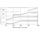
- the turbine generator control device 43 includes a load sharing control unit 53, a power turbine governor unit 55, a steam turbine governor unit 57, and a diesel engine generator 60 governor unit (not shown).
- the load sharing control unit 53 determines the load sharing of the power turbine 5, the steam turbine 10, and the diesel engine generator 60 according to the onboard demand power.
- the horizontal axis of FIG. 3 shows a percentage with respect to a rating of 100% of the onboard demand power.
- a power turbine (PT) 5, a steam turbine (ST) 10, a first diesel engine generator (DG1) 60, and a second diesel engine generator (DG2) 60 are arranged from the bottom, respectively.
- the vertical direction in the column of means the output.
- the output control described below is an example, and in the present embodiment, it is assumed that the outputs of the power turbine 5, the steam turbine 10, and the diesel engine generator 60 have almost the same ability, but the systems having different setting outputs. In this case, the control standard of onboard power demand is changed as appropriate to optimize the load sharing.
- the onboard demand power is 0 to 25%
- the output of the steam turbine 10 is gradually increased as the inboard demand power is increased while the output of the power turbine 5 is minimized, or the inboard demand power is decreased.
- the output of the steam turbine 10 is gradually reduced. In this way, the use of the steam turbine 10 preferentially eliminates the generation and dumping (discharge to the atmosphere) of surplus steam.
- the inboard demand power is 25 to 50%
- the outputs of the steam turbine 10 and the power turbine 5 are gradually increased as the inboard demand power increases, or the steam turbine 10 and the power turbine 5 are decreased as the inboard demand power decreases. Is gradually reduced.
- the output of the power turbine 5 increases or decreases so as to compensate for the difference between the onboard demand power and the output of the steam turbine 10, and the generation and dumping of surplus steam and discharge (discharge to the condenser) are abolished. is doing.
- the first diesel engine generator 60 starts up with a minimum output so as to supplement the onboard power demand. When the onboard power demand is 50 to 75%, the steam turbine 10 and the power turbine 5 output the rated output at a constant level. The output of the first diesel engine generator 60 is gradually increased as the inboard demand power increases, or the output of the first diesel engine generator 60 is gradually decreased as the inboard demand power decreases. Yes.
- the steam turbine 10, the power turbine 5, and the first diesel engine generator 60 output the rated output at a constant level.
- the output of the second diesel engine generator 60 is gradually increased as the inboard demand power increases, or the output of the second diesel engine generator 60 is gradually decreased as the inboard demand power decreases. Yes.
- the output signal corresponding to the load factor determined as shown in FIG. 3 is output from the load sharing control unit 53 to the power turbine governor unit 55, the steam turbine governor unit 57, and the diesel engine. Each is output to the governor section for the generator 60.
- the power turbine governor unit 55 is configured to control the turbine generator 25 based on a control function based on the set rotational speed droop control (proportional control) according to the output of the power turbine 5 instructed from the load sharing control unit 53.
- a control signal is calculated based on the deviation from the actual rotation speed detected by the rotation sensor 49 so as to stabilize the rotation speed fluctuation at the target rotation speed. Then, the control signal is output to the exhaust gas amount adjusting valve 33, the opening degree of the exhaust gas amount adjusting valve 33 is controlled, and the exhaust gas flow rate supplied to the power turbine 5 is controlled.
- the rotational speed droop control function is a function that calculates a control amount by applying a proportional gain to the deviation between the rotational speed target value and the current rotational speed that is actually controlled.
- the steam turbine governor unit 57 also sets the rotational speed droop control (proportional control) according to the output burden ratio of the steam turbine 10 instructed from the load sharing control unit 53.
- the control signal is calculated based on the deviation from the actual rotational speed detected by the rotation sensor 49 so that the rotational speed fluctuation of the turbine generator 25 is stabilized at the target rotational speed. .
- the control signal is output to the steam amount adjusting valve 37, the opening amount of the steam amount adjusting valve 37 is controlled, and the steam amount supplied to the steam turbine 10 is controlled.
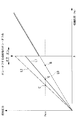
- FIG. 4 represents the engine load of the engine body 2, and the vertical axis represents the scavenging pressure.
- the first supercharger 3 is set so that only the second supercharger 4 is operated alone. Stop.
- the first supercharger 3 and the second supercharger 4 are operated in parallel. That is, when the engine load is equal to or less than a predetermined value, the first valve V1 and the third valve V3 are closed by the controller, and the first supercharger 3 is not operated (operated). Is higher than the predetermined value A, the first valve V1 and the third valve V3 are opened by the controller so that the first supercharger 3 operates normally.
- the controller automatically opens and closes the first valve V1 and the third valve V3 according to the engine load.
- a change in scavenging pressure of a normal turbo compound system in which the number of operating turbochargers is not switched according to the engine load is indicated by a broken line L0.
- the scavenging pressure increases linearly as the engine load increases.
- the change in the scavenging pressure of the turbocharging system of the sequential supercharging system that switches the number of operating turbochargers according to the engine load as in the present embodiment is shown by a solid line L1.
- the flow rate of the exhaust gas flowing into the second supercharger 4 increases accordingly, and the second supercharger is increased.
- the scavenging pressure supplied from 4 to the engine body 2 increases. Therefore, the minimum turbo load that satisfies the minimum scavenging pressure Pmin at which the power turbine 5 can be started and the exhaust heat can be recovered starts from the point B on the broken line L0 indicating the normal turbo compound system. It moves to the low load side to the point C on the solid line L1 indicating the compound system, and the operable region of the power turbine 5 is expanded.
- the minimum scavenging pressure at which the power turbine 5 can be started and the exhaust heat can be recovered is obtained from the pressure at which the power turbine 5 operates stably. Desired.
- the output of the power turbine 5 is decreased according to the decrease in the onboard power demand (see FIG. 3). Then, since the amount of exhaust gas extracted from the exhaust manifold 7 decreases, the amount of exhaust gas flowing to the second supercharger 4 increases. As a result, the scavenging pressure further increases as indicated by the one-dot chain line L2 in FIG. Since the scavenging pressure is further increased in this way, the minimum engine load at which the power turbine 5 can be started moves from the point C to the point C ′ further toward the low load side, and the operable range of the power turbine 5 is further expanded. To do. Even if the engine body 2 is operated in a low load region, the scavenging pressure increases, so that the output or efficiency of the engine body 2 can be improved.
- the turbo compound system and the operation method thereof According to the turbo compound system and the operation method thereof according to the present embodiment described above, the following operational effects can be obtained.
- the first supercharger 3 When the engine load of the engine body 2 is in a low load region of a predetermined value A or less, the first supercharger 3 is stopped, so that the amount of exhaust gas flowing into the second supercharger 4 increases accordingly.
- the scavenging pressure supplied from the second supercharger 4 to the engine body 2 will increase.
- the power turbine 5 can be started and the minimum scavenging pressure Pmin is obtained so that the exhaust heat can be recovered. Therefore, the exhaust heat energy from the engine body 2 is effective as power (power generation amount). It is possible to recover the energy and to further save energy.
- the scavenging pressure can be increased. Therefore, even if the engine main body 2 has a low load, the scavenging pressure can be increased and the output or efficiency of the engine main body 2 can be improved.
- the output of the power turbine 5 is reduced so as to compensate for the difference between the output of the steam turbine 10 and the demand power.
- the scavenging pressure is increased preferentially due to the decrease in the output of the power turbine 5, so that the output or efficiency of the engine body 2 can be improved.
- the output of the power turbine 5 is reduced so as to compensate for the difference between the output of the steam turbine 10 and the demand power, and the output of the power turbine 5 is preferentially reduced over the steam turbine 10. Therefore, excessive reduction of the output of the steam turbine 10 can be reduced as much as possible. As a result, excessively reducing the output of the steam turbine 10 makes it possible to avoid surplus steam generated by the exhaust gas economizer 11 and release it to the outside (for example, a condenser), and effectively exhaust heat from the engine body 2 without waste. Can be recovered.
- the present embodiment has been described with a configuration in which two exhaust turbine superchargers are provided, the present invention is not limited to this and may be three or more. Further, when the number of exhaust turbine superchargers is three or more, the number of exhaust turbine superchargers to be stopped when the engine main body 2 is low is not limited to one, and may be two or more.
- the marine turbo compound system has been described. However, the marine turbo compound system can also be used as an onshore turbo compound system.
Landscapes
- Engineering & Computer Science (AREA)
- Chemical & Material Sciences (AREA)
- Combustion & Propulsion (AREA)
- Mechanical Engineering (AREA)
- General Engineering & Computer Science (AREA)
- Chemical Kinetics & Catalysis (AREA)
- General Chemical & Material Sciences (AREA)
- Supercharger (AREA)
- Engine Equipment That Uses Special Cycles (AREA)
Abstract
省エネルギー性に優れ、出力ないし効率を向上させたターボコンパウンドシステムを提供することを目的とする。複数の排気タービン過給機(3,4)と、パワータービン(5)と、排ガスエコノマイザ(11)によって生成された蒸気によって駆動される蒸気タービン(10)と、パワータービン(5)および蒸気タービン(10)の回転軸に接続されたタービン発電機(25)と、排気タービン過給機(3,4)、パワータービン(5)及び蒸気タービン(10)の動作を制御する制御部とを備えたターボコンパウンドシステムにおいて、エンジン本体(2)の機関負荷が所定値以下である場合に、一方の排気タービン過給機(3)を停止させるとともに、エンジン本体(2)から抽気する排ガス量を減少させてパワータービン(5)の出力を減少させる。
Description
本発明は、舶用ディーゼル機関や陸上発電機用ディーゼル機関等を構成するエンジン本体から排出された排ガス(燃焼ガス)の排熱エネルギーを動力として回収するターボコンパウンドシステムおよびその運転方法に関するものである。
従来より、ディーゼルエンジンに対して複数の過給機を設け、負荷に応じて過給機の運転台数を切り替える運転方法が知られている(例えば、下記特許文献1参照)。
一方、複数台の過給機に加えて、ディーゼルエンジンからの排ガスよって駆動されるパワータービン及び蒸気タービンをさらに搭載したターボコンパウンドシステムを構成し、排ガスエネルギーを発電出力として回収して省エネルギー性をさらに向上させる試みがなされている。
しかしながら、複数台の過給機とパワータービン及び蒸気タービンとを搭載した場合に、省エネルギー性とエンジンの出力ないし効率の向上を両立させる運転システムや運転方法については検討されていない。
本発明は、このような事情に鑑みてなされたものであって、省エネルギー性に優れ、エンジンの出力ないし効率を向上させたターボコンパウンドシステムを提供することを目的とする。
上記課題を解決するために、本発明のターボコンパウンドシステムおよびその運転方法は以下の手段を採用する。
すなわち、本発明の第1の態様に係るターボコンパウンドシステムは、エンジン本体から導かれた排気ガスによって駆動される複数の排気タービン過給機と、これら排気タービン過給機の上流側から抽気された排ガスによって駆動されるパワータービンと、該パワータービンの回転軸に接続され、前記エンジン本体の排ガスを用いた排ガスボイラによって生成された蒸気によって駆動される蒸気タービンと、前記パワータービンおよび前記蒸気タービンの回転軸に接続された発電機と、前記排気タービン過給機、前記パワータービン及び前記蒸気タービンの動作を制御する制御部とを備えたターボコンパウンドシステムにおいて、前記制御部は、前記エンジン本体の機関負荷が所定値以下である場合に、前記排気タービン過給機のうちの少なくとも1台を停止させるとともに、船内需要電力がターボコンパウンドシステムの可能な最大発電出力よりも小さいときには、前記エンジン本体から抽気する排ガス量を減少させて前記パワータービンの出力を減少させる。
すなわち、本発明の第1の態様に係るターボコンパウンドシステムは、エンジン本体から導かれた排気ガスによって駆動される複数の排気タービン過給機と、これら排気タービン過給機の上流側から抽気された排ガスによって駆動されるパワータービンと、該パワータービンの回転軸に接続され、前記エンジン本体の排ガスを用いた排ガスボイラによって生成された蒸気によって駆動される蒸気タービンと、前記パワータービンおよび前記蒸気タービンの回転軸に接続された発電機と、前記排気タービン過給機、前記パワータービン及び前記蒸気タービンの動作を制御する制御部とを備えたターボコンパウンドシステムにおいて、前記制御部は、前記エンジン本体の機関負荷が所定値以下である場合に、前記排気タービン過給機のうちの少なくとも1台を停止させるとともに、船内需要電力がターボコンパウンドシステムの可能な最大発電出力よりも小さいときには、前記エンジン本体から抽気する排ガス量を減少させて前記パワータービンの出力を減少させる。
エンジン本体の機関負荷が所定値以下の低負荷領域にある場合には、排気タービン過給機のうちの少なくとも1台を停止させる。少なくとも1台の排気タービン過給機を停止させるので、その分だけ、他の排気タービン過給機に流入する排ガス流量が増加して、他の排気タービン過給機からエンジン本体へと供給される掃気圧力(過給空気(外気)の圧力)が上昇することとなる。これにより、エンジン本体の低負荷領域でも、パワータービンが起動可能となり排熱回収可能となる最低掃気圧力が得られるので、エンジン本体からの排熱エネルギーを動力(発電量)として有効に回収することができ、さらなる省エネルギー化を図ることができる。
さらに、船内需要電力がターボコンパウンドシステムの可能な最大発電出力よりも小さいときには、エンジン本体から抽気する排ガス量を減少させてパワータービンの出力を減少させるので、抽気する排ガス量を減少させることによって排気タービン過給機へと流れる排ガス量を増大させることで、掃気圧力を上昇させることができる。これにより、エンジン本体が低負荷であっても、掃気圧力を上昇させてエンジン本体の効率を向上させることができる。
上記のようにパワータービンの出力を減少させても、排ガスボイラによって熱回収する蒸気タービンによって発電できるので、必要な発電出力を確保することができる。
さらに、船内需要電力がターボコンパウンドシステムの可能な最大発電出力よりも小さいときには、エンジン本体から抽気する排ガス量を減少させてパワータービンの出力を減少させるので、抽気する排ガス量を減少させることによって排気タービン過給機へと流れる排ガス量を増大させることで、掃気圧力を上昇させることができる。これにより、エンジン本体が低負荷であっても、掃気圧力を上昇させてエンジン本体の効率を向上させることができる。
上記のようにパワータービンの出力を減少させても、排ガスボイラによって熱回収する蒸気タービンによって発電できるので、必要な発電出力を確保することができる。
さらに、本発明の第1の態様に係るターボコンパウンドシステムでは、前記制御部は、需要電力が減少した場合に、前記蒸気タービンの出力と前記需要電力との差分を補うように、前記パワータービンの出力を減少させる。
需要電力が減少した場合に、蒸気タービンの出力と需要電力との差分を補うように、パワータービンの出力を減少させることとした。これにより、パワータービンの出力減少による掃気圧力の上昇が優先的に行われるので、エンジン本体の効率の向上を実現することができる。
需要電力が減少した場合であっても、蒸気タービンの出力と需要電力との差分を補うようにパワータービンの出力を減少させて、蒸気タービンよりもパワータービンを優先的に出力減少させるので、蒸気タービンの出力を過剰に減少させることを可及的に減らすことができる。これにより、蒸気タービンの出力を過剰に減少させることにより排ガスボイラで生成した蒸気が余剰となり、外部(例えばコンデンサ)へ放出することを回避でき、エンジン本体からの排熱を無駄なく有効に回収することができる。
需要電力が減少した場合であっても、蒸気タービンの出力と需要電力との差分を補うようにパワータービンの出力を減少させて、蒸気タービンよりもパワータービンを優先的に出力減少させるので、蒸気タービンの出力を過剰に減少させることを可及的に減らすことができる。これにより、蒸気タービンの出力を過剰に減少させることにより排ガスボイラで生成した蒸気が余剰となり、外部(例えばコンデンサ)へ放出することを回避でき、エンジン本体からの排熱を無駄なく有効に回収することができる。
本発明の第2の態様にかかるターボコンパウンドシステムの運転方法は、エンジン本体から導かれた排気ガスによって駆動される複数の排気タービン過給機と、これら排気タービン過給機の上流側から抽気された排ガスによって駆動されるパワータービンと、該パワータービンの回転軸に接続され、前記エンジン本体の排ガスを用いた排ガスボイラによって生成された蒸気によって駆動される蒸気タービンと、前記パワータービンおよび前記蒸気タービンの回転軸に接続された発電機と、前記排気タービン過給機、前記パワータービン及び前記蒸気タービンの動作を制御する制御部とを備えたターボコンパウンドシステムの運転方法において、前記制御部は、前記エンジン本体の機関負荷が所定値以下である場合に、前記排気タービン過給機のうちの少なくとも1台を停止させるとともに、船内需要電力がターボコンパウンドシステムの可能な最大発電出力よりも小さいときには、前記エンジン本体から抽気する排ガス量を減少させて前記パワータービンの出力を減少させる。
エンジン本体の機関負荷が所定値以下の低負荷領域にある場合には、排気タービン過給機のうちの少なくとも1台を停止させる。少なくとも1台の排気タービン過給機を停止させるので、その分だけ、他の排気タービン過給機に流入する排ガス流量が増加して、他の排気タービン過給機からエンジン本体へと供給される掃気圧力(過給空気(外気)の圧力)が上昇することとなる。これにより、エンジン本体の低負荷領域でも、パワータービンが起動可能となり排熱回収可能となる最低掃気圧力が得られるので、エンジン本体からの排熱エネルギーを動力(発電量)として有効に回収することができ、さらなる省エネルギー化を図ることができる。
さらに、船内需要電力がターボコンパウンドシステムの可能な最大発電出力よりも小さいときには、エンジン本体から抽気する排ガス量を減少させてパワータービンの出力を減少させるので、抽気する排ガス量を減少させることによって排気タービン過給機へと流れる排ガス量を増大させることで、掃気圧力を上昇させることができる。これにより、エンジン本体が低負荷であっても、掃気圧力を上昇させてエンジン本体の効率を向上させることができる。
上記のようにパワータービンの出力を減少させても、排ガスボイラによって熱回収する蒸気タービンによって発電できるので、必要な発電出力を確保することができる。
さらに、船内需要電力がターボコンパウンドシステムの可能な最大発電出力よりも小さいときには、エンジン本体から抽気する排ガス量を減少させてパワータービンの出力を減少させるので、抽気する排ガス量を減少させることによって排気タービン過給機へと流れる排ガス量を増大させることで、掃気圧力を上昇させることができる。これにより、エンジン本体が低負荷であっても、掃気圧力を上昇させてエンジン本体の効率を向上させることができる。
上記のようにパワータービンの出力を減少させても、排ガスボイラによって熱回収する蒸気タービンによって発電できるので、必要な発電出力を確保することができる。
本発明のターボコンパウンドシステムおよびその運転方法によれば、以下の作用効果を奏する。
エンジン本体の機関負荷が所定値以下の低負荷領域にある場合に、排気タービン過給機のうちの少なくとも1台を停止させ、さらにエンジン本体から抽気する排ガス量を減少させてパワータービンの出力を減少させることとしたので、掃気圧力を上昇させた上でパワータービンの作動領域を大きくすることができ、省エネルギー性を向上させるだけでなく、エンジン本体の効率をも向上させることができる。
エンジン本体の機関負荷が所定値以下の低負荷領域にある場合に、排気タービン過給機のうちの少なくとも1台を停止させ、さらにエンジン本体から抽気する排ガス量を減少させてパワータービンの出力を減少させることとしたので、掃気圧力を上昇させた上でパワータービンの作動領域を大きくすることができ、省エネルギー性を向上させるだけでなく、エンジン本体の効率をも向上させることができる。
以下に、本発明に係るターボコンパウンドシステムおよびその運転方法の一実施形態について、図面を参照して説明する。
図1に示すように、本実施形態に係る舶用ディーゼル機関1は、ディーゼルエンジン本体(例えば、低速2サイクルディーゼル機関)2と、第1排気タービン過給機(主排気タービン過給機)3と、第2排気タービン過給機(副排気タービン過給機)4と、パワータービン5と、蒸気タービン10と、これらパワータービン5及び蒸気タービン10に対して接続されたタービン発電機25とを備えている。
図1に示すように、本実施形態に係る舶用ディーゼル機関1は、ディーゼルエンジン本体(例えば、低速2サイクルディーゼル機関)2と、第1排気タービン過給機(主排気タービン過給機)3と、第2排気タービン過給機(副排気タービン過給機)4と、パワータービン5と、蒸気タービン10と、これらパワータービン5及び蒸気タービン10に対して接続されたタービン発電機25とを備えている。
ディーゼルエンジン本体(以下「エンジン本体」という。)2を構成するクランク軸(図示せず)には、プロペラ軸(図示せず)を介してスクリュープロペラ(図示せず)が直接的または間接的に取り付けられている。エンジン本体2には、シリンダライナ(図示せず)、シリンダカバー(図示せず)等からなるシリンダ部6が設けられており、各シリンダ部6内には、クランク軸と連結されたピストン(図示せず)が配置されている。さらに、各シリンダ部6の排気ポート(図示せず)は、排気マニホールド7と接続されている。排気マニホールド7は、第1排気管L1を介して第1排気タービン過給機(以下「第1過給機」という。)3のタービン部3aの入口側と接続され、第2排気管L2を介して第2排気タービン過給機(以下「第2過給機」という。)4のタービン部4aの入口側と接続されているとともに、第3排気管L3を介してパワータービン5の入口側と接続されている。一方、各シリンダ部6の給気ポート(図示せず)は、給気マニホールド8と接続されており、給気マニホールド8は、第1給気管L4を介して第1過給機3のコンプレッサ部3bと接続され、第2給気管L5を介して第2過給機4のコンプレッサ部4bと接続されている。
第1過給機3は、第1排気管L1を介してエンジン本体2から導かれた排ガス(燃焼ガス)によって駆動されるタービン部3aと、このタービン部3aにより駆動されてエンジン本体2に外気を圧送するコンプレッサ部3bと、これらタービン部3aとコンプレッサ部3bとの間に設けられてこれらを支持するケーシング(図示せず)とを主たる要素として構成されたものである。
ケーシングには、一端部をタービン部3a側に突出させ、他端部をコンプレッサ部3bに突出させた回転軸3cが挿通されている。回転軸3cの一端部は、タービン部3aを構成するタービン・ロータ(図示せず)のタービン・ディスク(図示せず)に取り付けられており、回転軸3cの他端部は、コンプレッサ部3bを構成するコンプレッサ羽根車(図示せず)のハブ(図示せず)に取り付けられている。
第1排気管L1の途中には、図示しない制御器によって開閉される第1バルブV1が接続されている。コンプレッサ3bの出口側には、図示しない制御器によって開閉される第3バルブV3が接続されている。
ケーシングには、一端部をタービン部3a側に突出させ、他端部をコンプレッサ部3bに突出させた回転軸3cが挿通されている。回転軸3cの一端部は、タービン部3aを構成するタービン・ロータ(図示せず)のタービン・ディスク(図示せず)に取り付けられており、回転軸3cの他端部は、コンプレッサ部3bを構成するコンプレッサ羽根車(図示せず)のハブ(図示せず)に取り付けられている。
第1排気管L1の途中には、図示しない制御器によって開閉される第1バルブV1が接続されている。コンプレッサ3bの出口側には、図示しない制御器によって開閉される第3バルブV3が接続されている。
第2過給機4は、第2排気管L2を介してエンジン本体2から導かれた排気ガスによって駆動されるタービン部4aと、このタービン部4aにより駆動されてエンジン本体2に外気を圧送するコンプレッサ部4bと、これらタービン部4aとコンプレッサ部4bとの間に設けられてこれらを支持するケーシング(図示せず)とを主たる要素として構成されたものである。
ケーシングには、一端部をタービン部4a側に突出させ、他端部をコンプレッサ部4bに突出させた回転軸4cが挿通されている。回転軸4cの一端部は、タービン部4aを構成するタービン・ロータ(図示せず)のタービン・ディスク(図示せず)に取り付けられており、回転軸4cの他端部は、コンプレッサ部4bを構成するコンプレッサ羽根車(図示せず)のハブ(図示せず)に取り付けられている。
ケーシングには、一端部をタービン部4a側に突出させ、他端部をコンプレッサ部4bに突出させた回転軸4cが挿通されている。回転軸4cの一端部は、タービン部4aを構成するタービン・ロータ(図示せず)のタービン・ディスク(図示せず)に取り付けられており、回転軸4cの他端部は、コンプレッサ部4bを構成するコンプレッサ羽根車(図示せず)のハブ(図示せず)に取り付けられている。
コンプレッサ部3b,4bの入口側に接続された第1給気管L4および第2給気管L5の途中には、消音器(図示せず)がそれぞれ配置されており、この消音器を通過した外気が、コンプレッサ部3b,4bにそれぞれ導かれるようになっている。コンプレッサ部3b,4bの出口側に接続された第1給気管L4および第2給気管L5の途中には、空気冷却器(インタークーラ)9や図示しないサージタンク等が接続されており、コンプレッサ部3b,4bを通過した外気は、これら空気冷却器9やサージタンク等を通過した後、エンジン本体2の給気マニホールド8に供給されるようになっている。
パワータービン5は、第3排気管L3を介して排気マニホールド7から抽気された排ガスによって回転駆動されるようになっており、蒸気タービン10は、排ガスエコノマイザ11によって生成された蒸気が供給されて回転駆動されるようになっている。
この排ガスエコノマイザ11には、第1過給機3のタービン部3aおよび第2過給機4のタービン部4aからの排ガスが第6排気管L6を介して導入される。さらに、排ガスエコノマイザ11には、パワータービン5の出口側から第7排気管L7を介して排出される排ガスが導入される。排ガスエコノマイザ11の熱交換部21では、導入された排ガスの熱によって給水管23から供給された水が加熱・蒸発されて蒸気が発生する。熱交換部21で生成された蒸気は第1蒸気管J1を介して蒸気タービン10に導入され、この蒸気タービン10で仕事を終えた蒸気は第2蒸気管J2によって排出されて図示しないコンデンサ(復水器)に導かれる。
この排ガスエコノマイザ11には、第1過給機3のタービン部3aおよび第2過給機4のタービン部4aからの排ガスが第6排気管L6を介して導入される。さらに、排ガスエコノマイザ11には、パワータービン5の出口側から第7排気管L7を介して排出される排ガスが導入される。排ガスエコノマイザ11の熱交換部21では、導入された排ガスの熱によって給水管23から供給された水が加熱・蒸発されて蒸気が発生する。熱交換部21で生成された蒸気は第1蒸気管J1を介して蒸気タービン10に導入され、この蒸気タービン10で仕事を終えた蒸気は第2蒸気管J2によって排出されて図示しないコンデンサ(復水器)に導かれる。
パワータービン5と蒸気タービン10とは直列に結合されてタービン発電機25を駆動するようになっている。蒸気タービン10の回転軸29は図示しない減速機およびカップリングを介してタービン発電機25に接続され、パワータービン5の回転軸27は図示しない減速機およびクラッチ31を介して蒸気タービン10の回転軸29と連結されている。クラッチ31としては、所定の回転数にて嵌脱されるクラッチが用いられ、例えばSSS(Synchro-Self-Shifting)クラッチが好適に用いられる。
第3排気管L3には、パワータービン5に導入するガス量を制御する排ガス量調整弁33と、非常時にパワータービン5への排ガスの供給を遮断する非常停止用緊急遮断弁35とが設けられている。非常停止用緊急遮断弁35が遮断したときに、各過給機3,4のタービン部3a,4aへの過過給(エンジンの最適運転圧力を超えての過給)を防止するためにバイパス弁34が第7排気管L7との間に設けられている。
さらに、第1蒸気管J1には、蒸気タービン10に導入する蒸気量を制御する蒸気量調整弁37と、非常時に蒸気タービン10への蒸気の供給を遮断する非常停止用緊急遮断弁39とが設置されている。
上述の排ガス量調整弁33および蒸気量調整弁37は、図2を用いて説明するタービン発電機制御装置43によって、その開度が制御される。
以上のようにタービン発電機25は、エンジン本体2の排ガス(燃焼ガス)の排気エネルギーを動力として駆動されるようになっている。
上述の排ガス量調整弁33および蒸気量調整弁37は、図2を用いて説明するタービン発電機制御装置43によって、その開度が制御される。
以上のようにタービン発電機25は、エンジン本体2の排ガス(燃焼ガス)の排気エネルギーを動力として駆動されるようになっている。
図2には、図1に示したタービン発電機25を有する発電システムの制御装置の概略構成が示されている。
図2に示したタービン発電機制御装置43は、第1過給機3及び第2過給機4を制御する船内制御装置の一部を構成する。
図2に示したタービン発電機制御装置43は、第1過給機3及び第2過給機4を制御する船内制御装置の一部を構成する。
発電システムは、タービン発電機25に加え、船内に別途設置された複数(本実施形態では2台)のディーゼルエンジン発電機60を備えている。
タービン発電機制御装置43には、タービン発電機25の出力電力を検出する電力センサ45からの信号が入力され、タービン発電機25の回転速度として蒸気タービン10の回転軸29の回転速度を検出する回転センサ49からの信号が入力されている。タービン発電機制御装置43には、ディーゼルエンジン発電機60からの出力信号と、船内消費電力を検出する船内消費電力センサ51からの信号とが入力されている。
タービン発電機制御装置43には、タービン発電機25の出力電力を検出する電力センサ45からの信号が入力され、タービン発電機25の回転速度として蒸気タービン10の回転軸29の回転速度を検出する回転センサ49からの信号が入力されている。タービン発電機制御装置43には、ディーゼルエンジン発電機60からの出力信号と、船内消費電力を検出する船内消費電力センサ51からの信号とが入力されている。
タービン発電機制御装置43は、負荷分担制御部53と、パワータービン用ガバナー部55と、蒸気タービン用ガバナー部57と、ディーゼルエンジン発電機60用ガバナー部(図示せず)とを備えている。
負荷分担制御部53では、図3に示すように、船内需要電力に応じて、パワータービン5、蒸気タービン10及びディーゼルエンジン発電機60の負荷分担を決定する。
図3の横軸は、船内需要電力の定格100%に対する百分率を示している。縦軸方向には、下からパワータービン(PT)5,蒸気タービン(ST)10,第1ディーゼルエンジン発電機(DG1)60、第2ディーゼルエンジン発電機(DG2)60が並べられており、それぞれの欄の縦方向は出力を意味する。以下に説明する出力制御は一例であり、本実施形態ではパワータービン5、蒸気タービン10、ディーゼルエンジン発電機60の出力がほぼ同等の能力を有する構成を想定しているが、設定出力が異なるシステムにおいては、船内需要電力の制御基準を適宜変更し、負荷分担の最適化を図ることになる。
図3の横軸は、船内需要電力の定格100%に対する百分率を示している。縦軸方向には、下からパワータービン(PT)5,蒸気タービン(ST)10,第1ディーゼルエンジン発電機(DG1)60、第2ディーゼルエンジン発電機(DG2)60が並べられており、それぞれの欄の縦方向は出力を意味する。以下に説明する出力制御は一例であり、本実施形態ではパワータービン5、蒸気タービン10、ディーゼルエンジン発電機60の出力がほぼ同等の能力を有する構成を想定しているが、設定出力が異なるシステムにおいては、船内需要電力の制御基準を適宜変更し、負荷分担の最適化を図ることになる。
船内需要電力が0~25%の場合、パワータービン5の出力を最小に抑えつつ、船内需要電力の増大に応じて蒸気タービン10の出力が漸次増大され、或いは、船内需要電力の減少に応じて蒸気タービン10の出力が漸次減少されるようになっている。このように、優先的に蒸気タービン10を用いることとして、余剰蒸気の生成およびダンプ(大気への放出)を廃止している。
船内需要電力が25~50%の場合、船内需要電力の増大に応じて蒸気タービン10及びパワータービン5の出力が漸次増大され、或いは、船内需要電力の減少に応じて蒸気タービン10及びパワータービン5の出力が漸次減少されるようになっている。この場合、パワータービン5の出力は、船内需要電力と蒸気タービン10の出力との差分を補うように増大ないし減少するようになっており、余剰蒸気の生成およびダンプ(コンデンサへの放出)を廃止している。船内需要電力を補うように、第1ディーゼルエンジン発電機60が最小出力で立ち上がる。
船内需要電力が50~75%の場合、蒸気タービン10及びパワータービン5は定格出力を一定に出力する。船内需要電力の増大に応じて第1ディーゼルエンジン発電機60の出力が漸次増大され、或いは、船内需要電力の減少に応じて第1ディーゼルエンジン発電機60の出力が漸次減少されるようになっている。
船内需要電力が75~100%の場合、蒸気タービン10及びパワータービン5並びに第1ディーゼルエンジン発電機60は定格出力を一定に出力する。船内需要電力の増大に応じて第2ディーゼルエンジン発電機60の出力が漸次増大され、或いは、船内需要電力の減少に応じて第2ディーゼルエンジン発電機60の出力が漸次減少されるようになっている。
図3に示したように決定された負荷率に応じた出力信号が、図2に示したように、負荷分担制御部53からパワータービン用ガバナー部55、蒸気タービン用ガバナー部57、及びディーゼルエンジン発電機60用ガバナー部にそれぞれ出力される。
パワータービン用ガバナー部55は、負荷分担制御部53から指示されたパワータービン5の出力に応じて、設定されている回転数ドループ制御(比例制御)による制御関数に基づいて、タービン発電機25の回転速度変動に対して目標回転速度に安定させるように、回転センサ49で検出される実回転速度との偏差を基に制御信号が算出される。そして、該制御信号が排ガス量調整弁33に出力され、排ガス量調整弁33の開度が制御されてパワータービン5に供給される排ガス流量が制御される。この回転数ドループ制御関数とは、回転速度目標値と実際に制御された現在の回転速度との偏差に比例ゲインをかけることにより制御量を演算する関数である。
蒸気タービン用ガバナー部57においても、パワータービン用ガバナー部55と同様に、負荷分担制御部53から指示された蒸気タービン10の出力負担割合に応じて、設定されている回転数ドループ制御(比例制御)による制御関数に基づいて、タービン発電機25の回転速度変動に対して目標回転速度に安定させるように、回転センサ49で検出される実回転速度との偏差を基に制御信号が算出される。そして、該制御信号が蒸気量調整弁37に出力され、該蒸気量調整弁37の開度が制御されて蒸気タービン10に供給される蒸気量が制御されるようになっている。
次に、図4を用いて、上記構成のターボコンパウンドシステムの運転方法について説明する。
図4の横軸はエンジン本体2の機関負荷を示し、縦軸は掃気圧力を示す。
同図に示されているように、エンジン本体2の機関負荷が所定値A以下の低負荷領域の場合には、第2過給機4のみを単独運転するように第1過給機3を停止させる。そして、エンジン本体2の機関負荷が所定値Aよりも高い場合には、第1過給機3と第2過給機4とを並列運転させる。すなわち、機関負荷が所定値以下の場合には、制御器によって第1バルブV1および第3バルブV3が閉塞されて、第1過給機3が作動(運転)しないようになっており、機関負荷が所定値Aよりも高い場合には、制御器によって第1バルブV1および第3バルブV3が開放されて、第1過給機3が通常運転するようになっている。第1バルブV1および第3バルブV3の開閉は、機関負荷に応じて制御器が自動的に行っている。
図4には、機関負荷に応じて過給機の運転台数の切替えを行わない通常のターボコンパウンドシステムの掃気圧力の変化が破線L0にて示されている。同図に示されているように、機関負荷が増大するにつれて線形的に掃気圧力が増大するようになっている。
これに対して、本実施形態のように機関負荷に応じて過給機の運転台数の切替えを行うシーケンシャル過給方式のターボコンパウンドシステムの掃気圧力の変化が実線L1にて示されている。同図に示されているように、低負荷領域では、第1過給機3を停止させるので、その分だけ第2過給機4に流入する排ガス流量が増加して、第2過給機4からエンジン本体2へと供給される掃気圧力が上昇する。したがって、パワータービン5が起動可能となり排熱回収可能となる最低掃気圧力Pminを満たす最小機関負荷が、通常のターボコンパウンドシステムを示す破線L0上のB点から、本実施形態のシーケンシャル過給方式ターボコンパウンドシステムを示す実線L1上のC点へと低負荷側に移動し、パワータービン5の運転可能領域が拡大する。パワータービン5が起動可能となり排熱回収可能となる最低掃気圧力は、パワータービン5が安定的に動作する圧力から得られ、例えば、クラッチ31(図1参照)が嵌脱する回転数を基準として求められる。
これに対して、本実施形態のように機関負荷に応じて過給機の運転台数の切替えを行うシーケンシャル過給方式のターボコンパウンドシステムの掃気圧力の変化が実線L1にて示されている。同図に示されているように、低負荷領域では、第1過給機3を停止させるので、その分だけ第2過給機4に流入する排ガス流量が増加して、第2過給機4からエンジン本体2へと供給される掃気圧力が上昇する。したがって、パワータービン5が起動可能となり排熱回収可能となる最低掃気圧力Pminを満たす最小機関負荷が、通常のターボコンパウンドシステムを示す破線L0上のB点から、本実施形態のシーケンシャル過給方式ターボコンパウンドシステムを示す実線L1上のC点へと低負荷側に移動し、パワータービン5の運転可能領域が拡大する。パワータービン5が起動可能となり排熱回収可能となる最低掃気圧力は、パワータービン5が安定的に動作する圧力から得られ、例えば、クラッチ31(図1参照)が嵌脱する回転数を基準として求められる。
そして、本実施形態では、船内需要電力の減少に応じて(図3参照)、パワータービン5の出力が減少させられる。すると、排気マニホールド7から抽気される排ガス量が減少するので、第2過給機4へと流れる排ガス量が増大する。これにより、図4の一点鎖線L2で示すように、掃気圧力がさらに上昇する。このように掃気圧力がさらに上昇するので、パワータービン5が起動可能となる最小機関負荷がC点からC’点へとさらに低負荷側へと移動し、パワータービン5の運転可能領域がさらに拡大する。エンジン本体2が低負荷領域で運転されていても、掃気圧力が増大するので、エンジン本体2の出力ないし効率を向上させることができる。
上述した本実施形態にかかるターボコンパウンドシステムおよびその運転方法によれば、以下の作用効果を奏する。
エンジン本体2の機関負荷が所定値A以下の低負荷領域にある場合には、第1過給機3を停止させるので、その分だけ第2過給機4に流入する排ガス流量が増加して、第2過給機4からエンジン本体2へと供給される掃気圧力が上昇することとなる。これにより、エンジン本体2の低負荷領域でも、パワータービン5が起動可能となり排熱回収可能となる最低掃気圧力Pminが得られるので、エンジン本体2からの排熱エネルギーを動力(発電量)として有効に回収することができ、さらなる省エネルギー化を図ることができる。
エンジン本体2の機関負荷が所定値A以下の低負荷領域にある場合には、第1過給機3を停止させるので、その分だけ第2過給機4に流入する排ガス流量が増加して、第2過給機4からエンジン本体2へと供給される掃気圧力が上昇することとなる。これにより、エンジン本体2の低負荷領域でも、パワータービン5が起動可能となり排熱回収可能となる最低掃気圧力Pminが得られるので、エンジン本体2からの排熱エネルギーを動力(発電量)として有効に回収することができ、さらなる省エネルギー化を図ることができる。
さらに、エンジン本体2から抽気する排ガス量を減少させてパワータービン5の出力を減少させるので、抽気する排ガス量を減少させることによって第2過給機4へと流れる排ガス量を増大させることで、掃気圧力を上昇させることができる。これにより、エンジン本体2が低負荷であっても、掃気圧力を上昇させてエンジン本体2の出力ないし効率を向上させることができる。
パワータービン5の出力を減少させても、排ガスエコノマイザ11によって熱回収する蒸気タービン10によって発電できるので、必要な発電出力を確保することができる。
需要電力が減少した場合に、蒸気タービン10の出力と需要電力との差分を補うように、パワータービン5の出力を減少させることとした。これにより、パワータービン5の出力減少による掃気圧力の上昇が優先的に行われるので、エンジン本体2の出力ないし効率の向上を実現することができる。
需要電力が減少した場合であっても、蒸気タービン10の出力と需要電力との差分を補うようにパワータービン5の出力を減少させて、蒸気タービン10よりもパワータービン5を優先的に出力減少させるので、蒸気タービン10の出力を過剰に減少させることを可及的に減らすことができる。これにより、蒸気タービン10の出力を過剰に減少させることにより排ガスエコノマイザ11で生成した蒸気が余剰となり、外部(例えばコンデンサ)へ放出することを回避でき、エンジン本体2からの排熱を無駄なく有効に回収することができる。
本実施形態では、排気タービン過給機を2台とした構成で説明したが、本発明はこれに限定されるものではなく、3台以上としても良い。また、排気タービン過給機を3台以上とする場合、エンジン本体2の低負荷時に停止させる排気タービン過給機は1台に限らず、2台以上であっても良い。
本実施形態では、舶用のターボコンパウンドシステムについて説明したが、陸上用のターボコンパウンドシステムとしても用いることができる。
本実施形態では、舶用のターボコンパウンドシステムについて説明したが、陸上用のターボコンパウンドシステムとしても用いることができる。
1 舶用ディーゼル機関
2 エンジン本体
3 第1過給機(排気タービン過給機)
4 第2過給機(排気タービン過給機)
5 パワータービン
10 蒸気タービン
11 排ガスエコノマイザ(排ガスボイラ)
25 タービン発電機
2 エンジン本体
3 第1過給機(排気タービン過給機)
4 第2過給機(排気タービン過給機)
5 パワータービン
10 蒸気タービン
11 排ガスエコノマイザ(排ガスボイラ)
25 タービン発電機
Claims (3)
- エンジン本体から導かれた排気ガスによって駆動される複数の排気タービン過給機と、
これら排気タービン過給機の上流側から抽気された排ガスによって駆動されるパワータービンと、
該パワータービンの回転軸に接続され、前記エンジン本体の排ガスを用いた排ガスボイラによって生成された蒸気によって駆動される蒸気タービンと、
前記パワータービンおよび前記蒸気タービンの回転軸に接続された発電機と、
前記排気タービン過給機、前記パワータービン及び前記蒸気タービンの動作を制御する制御部と、
を備えたターボコンパウンドシステムにおいて、
前記制御部は、前記エンジン本体の機関負荷が所定値以下である場合に、前記排気タービン過給機のうちの少なくとも1台を停止させるとともに、船内需要電力がターボコンパウンドシステムの可能な最大発電出力よりも小さいときには、前記エンジン本体から抽気する排ガス量を減少させて前記パワータービンの出力を減少させるターボコンパウンドシステム。 - 前記制御部は、需要電力が減少した場合に、前記蒸気タービンの出力と前記需要電力との差分を補うように、前記パワータービンの出力を減少させる請求項1に記載のターボコンパウンドシステム。
- エンジン本体から導かれた排気ガスによって駆動される複数の排気タービン過給機と、
これら排気タービン過給機の上流側から抽気された排ガスによって駆動されるパワータービンと、
該パワータービンの回転軸に接続され、前記エンジン本体の排ガスを用いた排ガスボイラによって生成された蒸気によって駆動される蒸気タービンと、
前記パワータービンおよび前記蒸気タービンの回転軸に接続された発電機と、
前記排気タービン過給機、前記パワータービン及び前記蒸気タービンの動作を制御する制御部と、
を備えたターボコンパウンドシステムの運転方法において、
前記制御部は、前記エンジン本体の機関負荷が所定値以下である場合に、前記排気タービン過給機のうちの少なくとも1台を停止させるとともに、船内需要電力がターボコンパウンドシステムの可能な最大発電出力よりも小さいときには、前記エンジン本体から抽気する排ガス量を減少させて前記パワータービンの出力を減少させるターボコンパウンドシステムの運転方法。
Priority Applications (3)
| Application Number | Priority Date | Filing Date | Title |
|---|---|---|---|
| EP10825032.5A EP2492458B1 (en) | 2009-10-23 | 2010-10-21 | Turbo compound system and method for operating same |
| DK10825032.5T DK2492458T3 (en) | 2009-10-23 | 2010-10-21 | Turbo-Compound System and Method of Use |
| KR1020127009918A KR101234466B1 (ko) | 2009-10-23 | 2010-10-21 | 터보 컴파운드 시스템 및 그 운전 방법 |
Applications Claiming Priority (2)
| Application Number | Priority Date | Filing Date | Title |
|---|---|---|---|
| JP2009-244382 | 2009-10-23 | ||
| JP2009244382A JP5155980B2 (ja) | 2009-10-23 | 2009-10-23 | ターボコンパウンドシステムおよびその運転方法 |
Publications (1)
| Publication Number | Publication Date |
|---|---|
| WO2011049183A1 true WO2011049183A1 (ja) | 2011-04-28 |
Family
ID=43900406
Family Applications (1)
| Application Number | Title | Priority Date | Filing Date |
|---|---|---|---|
| PCT/JP2010/068634 Ceased WO2011049183A1 (ja) | 2009-10-23 | 2010-10-21 | ターボコンパウンドシステムおよびその運転方法 |
Country Status (5)
| Country | Link |
|---|---|
| EP (1) | EP2492458B1 (ja) |
| JP (1) | JP5155980B2 (ja) |
| KR (1) | KR101234466B1 (ja) |
| DK (1) | DK2492458T3 (ja) |
| WO (1) | WO2011049183A1 (ja) |
Cited By (2)
| Publication number | Priority date | Publication date | Assignee | Title |
|---|---|---|---|---|
| JP2014084853A (ja) * | 2012-10-26 | 2014-05-12 | Mitsubishi Heavy Ind Ltd | 内燃機関システムおよびこれを備えた船舶ならびに内燃機関システムの運転方法 |
| CN114352402A (zh) * | 2022-01-17 | 2022-04-15 | 中船重工(重庆)西南装备研究院有限公司 | 一种增压器自适应控制系统 |
Families Citing this family (13)
| Publication number | Priority date | Publication date | Assignee | Title |
|---|---|---|---|---|
| JP4934468B2 (ja) | 2006-11-17 | 2012-05-16 | 古河電気工業株式会社 | 電線の端子圧着装置及び電線の端子圧着方法 |
| JP5185910B2 (ja) * | 2009-10-16 | 2013-04-17 | 三菱重工業株式会社 | ミラーサイクルエンジン |
| US9166303B2 (en) | 2011-08-15 | 2015-10-20 | Dmc Power, Inc. | Full tension swaged connector for reinforced cable |
| WO2014022208A1 (en) * | 2012-08-01 | 2014-02-06 | Borgwarner Inc. | System and method of using a turbo alternator in an exhaust gas system to generate power |
| KR101449141B1 (ko) * | 2012-11-07 | 2014-10-08 | 현대자동차주식회사 | 차량의 폐열 회수 시스템을 이용한 터보장치 |
| JP5571151B2 (ja) * | 2012-11-09 | 2014-08-13 | 三菱重工業株式会社 | 船舶推進装置、船舶、及び船舶推進方法 |
| CN102966428A (zh) * | 2012-11-12 | 2013-03-13 | 上海交通大学 | 船用发动机外围气路系统 |
| GB2508866B (en) * | 2012-12-13 | 2020-05-20 | Bowman Power Group Ltd | Turbogenerator system and method |
| JP5563052B2 (ja) * | 2012-12-14 | 2014-07-30 | 三菱重工業株式会社 | 排熱回収システム及び排熱回収方法 |
| GB2509103B (en) | 2012-12-20 | 2020-05-06 | Bowman Power Group Ltd | Method and apparatus for controlling a turbogenerator system |
| KR101366469B1 (ko) | 2013-04-24 | 2014-02-25 | 현대중공업 주식회사 | 내연기관 시스템 |
| KR200490813Y1 (ko) | 2017-07-31 | 2020-01-17 | (주) 봄날애 | 의료용 침대의 보조난간장치 |
| CN108757164A (zh) * | 2018-07-10 | 2018-11-06 | 福州大学 | 提高发动机废气涡轮发电效率的装置及方法 |
Citations (8)
| Publication number | Priority date | Publication date | Assignee | Title |
|---|---|---|---|---|
| JPS60166716A (ja) | 1984-02-08 | 1985-08-30 | Mitsubishi Heavy Ind Ltd | デイ−ゼルエンジンの過給機切換運転方法 |
| JPS61113196U (ja) * | 1984-12-28 | 1986-07-17 | ||
| JPS61244806A (ja) * | 1985-04-19 | 1986-10-31 | Mitsubishi Heavy Ind Ltd | 発電システム |
| JPS63183225A (ja) * | 1987-01-22 | 1988-07-28 | Ishikawajima Harima Heavy Ind Co Ltd | パワ−タ−ビン付デイ−ゼル機関の運転方法 |
| JPS63302138A (ja) * | 1987-05-16 | 1988-12-09 | エム・アー・エヌ・‐ベー・ウント・ヴエー・デイーゼル・ゲゼルシヤフト・ミツト・ベシユレンクテル・ハフツング | 燃焼機関設備 |
| JPH01195924A (ja) * | 1987-09-01 | 1989-08-07 | Man B & W Diesel Gmbh | 内燃機関設備 |
| JPH03164526A (ja) * | 1989-12-19 | 1991-07-16 | Mitsubishi Heavy Ind Ltd | 複合内燃機関 |
| WO2008135059A1 (en) * | 2007-05-03 | 2008-11-13 | Man Diesel Filial Af Man Diesel Se, Tyskland | Large supercharged diesel engine with scr reactor |
Family Cites Families (3)
| Publication number | Priority date | Publication date | Assignee | Title |
|---|---|---|---|---|
| JPH081133B2 (ja) * | 1989-09-01 | 1996-01-10 | マツダ株式会社 | ターボ過給機付エンジンの過給圧制御装置 |
| JPH09256814A (ja) * | 1996-03-22 | 1997-09-30 | Mitsubishi Heavy Ind Ltd | ディーゼル機関プラント |
| JP4797946B2 (ja) * | 2006-11-22 | 2011-10-19 | トヨタ自動車株式会社 | 内燃機関の過給機制御装置 |
-
2009
- 2009-10-23 JP JP2009244382A patent/JP5155980B2/ja active Active
-
2010
- 2010-10-21 EP EP10825032.5A patent/EP2492458B1/en active Active
- 2010-10-21 KR KR1020127009918A patent/KR101234466B1/ko active Active
- 2010-10-21 DK DK10825032.5T patent/DK2492458T3/en active
- 2010-10-21 WO PCT/JP2010/068634 patent/WO2011049183A1/ja not_active Ceased
Patent Citations (8)
| Publication number | Priority date | Publication date | Assignee | Title |
|---|---|---|---|---|
| JPS60166716A (ja) | 1984-02-08 | 1985-08-30 | Mitsubishi Heavy Ind Ltd | デイ−ゼルエンジンの過給機切換運転方法 |
| JPS61113196U (ja) * | 1984-12-28 | 1986-07-17 | ||
| JPS61244806A (ja) * | 1985-04-19 | 1986-10-31 | Mitsubishi Heavy Ind Ltd | 発電システム |
| JPS63183225A (ja) * | 1987-01-22 | 1988-07-28 | Ishikawajima Harima Heavy Ind Co Ltd | パワ−タ−ビン付デイ−ゼル機関の運転方法 |
| JPS63302138A (ja) * | 1987-05-16 | 1988-12-09 | エム・アー・エヌ・‐ベー・ウント・ヴエー・デイーゼル・ゲゼルシヤフト・ミツト・ベシユレンクテル・ハフツング | 燃焼機関設備 |
| JPH01195924A (ja) * | 1987-09-01 | 1989-08-07 | Man B & W Diesel Gmbh | 内燃機関設備 |
| JPH03164526A (ja) * | 1989-12-19 | 1991-07-16 | Mitsubishi Heavy Ind Ltd | 複合内燃機関 |
| WO2008135059A1 (en) * | 2007-05-03 | 2008-11-13 | Man Diesel Filial Af Man Diesel Se, Tyskland | Large supercharged diesel engine with scr reactor |
Non-Patent Citations (1)
| Title |
|---|
| See also references of EP2492458A4 * |
Cited By (3)
| Publication number | Priority date | Publication date | Assignee | Title |
|---|---|---|---|---|
| JP2014084853A (ja) * | 2012-10-26 | 2014-05-12 | Mitsubishi Heavy Ind Ltd | 内燃機関システムおよびこれを備えた船舶ならびに内燃機関システムの運転方法 |
| CN114352402A (zh) * | 2022-01-17 | 2022-04-15 | 中船重工(重庆)西南装备研究院有限公司 | 一种增压器自适应控制系统 |
| CN114352402B (zh) * | 2022-01-17 | 2024-05-28 | 中船重工(重庆)西南装备研究院有限公司 | 一种增压器自适应控制系统 |
Also Published As
| Publication number | Publication date |
|---|---|
| JP5155980B2 (ja) | 2013-03-06 |
| KR20120068924A (ko) | 2012-06-27 |
| DK2492458T3 (en) | 2017-03-20 |
| EP2492458B1 (en) | 2016-12-07 |
| EP2492458A4 (en) | 2015-06-03 |
| KR101234466B1 (ko) | 2013-02-18 |
| JP2011089488A (ja) | 2011-05-06 |
| EP2492458A1 (en) | 2012-08-29 |
Similar Documents
| Publication | Publication Date | Title |
|---|---|---|
| JP5155980B2 (ja) | ターボコンパウンドシステムおよびその運転方法 | |
| JP6294646B2 (ja) | ターボコンパウンドシステムの制御装置 | |
| JP4950082B2 (ja) | 舶用ディーゼル機関 | |
| CN103026037B (zh) | 发动机排气能量回收装置 | |
| JP5173776B2 (ja) | 排気エネルギー回収装置 | |
| JP7642674B2 (ja) | 船舶のための空気供給装置、この装置を含む船舶、及び空気潤滑デバイスに空気を供給する方法 | |
| JP5138643B2 (ja) | タービン発電機、タービン発電機の制御方法、制御装置、および該タービン発電機を備えた船舶 | |
| CN102959185B (zh) | 涡轮发电机的控制方法及装置 | |
| JP2011027053A5 (ja) | ||
| CN104838094B (zh) | 废热回收系统及废热回收方法 | |
| JP5448703B2 (ja) | 舶用ディーゼル機関 | |
| WO2016175194A1 (ja) | 内燃機関の過給機余剰動力回収装置 | |
| JP6370716B2 (ja) | 過給システム及び過給システムの運転方法 | |
| JP5804756B2 (ja) | 過給機システム、内燃機関及び過給機システムの制御方法 | |
| JP2013029111A (ja) | 発電方法、タービン発電機、タービン発電機の制御方法、制御装置、および該タービン発電機を備えた船舶 | |
| JP5449509B2 (ja) | 排気エネルギー回収方法および排気エネルギー回収装置 | |
| JP5675932B2 (ja) | 発電方法、タービン発電機、タービン発電機の制御方法、制御装置、および該タービン発電機を備えた船舶 |
Legal Events
| Date | Code | Title | Description |
|---|---|---|---|
| 121 | Ep: the epo has been informed by wipo that ep was designated in this application |
Ref document number: 10825032 Country of ref document: EP Kind code of ref document: A1 |
|
| REEP | Request for entry into the european phase |
Ref document number: 2010825032 Country of ref document: EP |
|
| WWE | Wipo information: entry into national phase |
Ref document number: 2010825032 Country of ref document: EP |
|
| ENP | Entry into the national phase |
Ref document number: 20127009918 Country of ref document: KR Kind code of ref document: A |