WO2011052236A1 - 立体表示装置および立体表示システム - Google Patents
立体表示装置および立体表示システム Download PDFInfo
- Publication number
- WO2011052236A1 WO2011052236A1 PCT/JP2010/006443 JP2010006443W WO2011052236A1 WO 2011052236 A1 WO2011052236 A1 WO 2011052236A1 JP 2010006443 W JP2010006443 W JP 2010006443W WO 2011052236 A1 WO2011052236 A1 WO 2011052236A1
- Authority
- WO
- WIPO (PCT)
- Prior art keywords
- control unit
- backlight
- eye
- open
- video
- Prior art date
- Legal status (The legal status is an assumption and is not a legal conclusion. Google has not performed a legal analysis and makes no representation as to the accuracy of the status listed.)
- Ceased
Links
Images


Classifications
-
- G—PHYSICS
- G02—OPTICS
- G02B—OPTICAL ELEMENTS, SYSTEMS OR APPARATUS
- G02B30/00—Optical systems or apparatus for producing three-dimensional [3D] effects, e.g. stereoscopic images
- G02B30/20—Optical systems or apparatus for producing three-dimensional [3D] effects, e.g. stereoscopic images by providing first and second parallax images to an observer's left and right eyes
- G02B30/22—Optical systems or apparatus for producing three-dimensional [3D] effects, e.g. stereoscopic images by providing first and second parallax images to an observer's left and right eyes of the stereoscopic type
- G02B30/24—Optical systems or apparatus for producing three-dimensional [3D] effects, e.g. stereoscopic images by providing first and second parallax images to an observer's left and right eyes of the stereoscopic type involving temporal multiplexing, e.g. using sequentially activated left and right shutters
-
- H—ELECTRICITY
- H04—ELECTRIC COMMUNICATION TECHNIQUE
- H04N—PICTORIAL COMMUNICATION, e.g. TELEVISION
- H04N13/00—Stereoscopic video systems; Multi-view video systems; Details thereof
- H04N13/30—Image reproducers
- H04N13/332—Displays for viewing with the aid of special glasses or head-mounted displays [HMD]
- H04N13/341—Displays for viewing with the aid of special glasses or head-mounted displays [HMD] using temporal multiplexing
-
- H—ELECTRICITY
- H04—ELECTRIC COMMUNICATION TECHNIQUE
- H04N—PICTORIAL COMMUNICATION, e.g. TELEVISION
- H04N13/00—Stereoscopic video systems; Multi-view video systems; Details thereof
- H04N13/30—Image reproducers
- H04N13/398—Synchronisation thereof; Control thereof
Definitions
- the present invention relates to a stereoscopic display system for observing a stereoscopic image using glasses for stereoscopic image observation and a stereoscopic display device used therefor.
- a stereoscopic display device for obtaining a stereoscopic image a left-eye video and a right-eye video having parallax are alternately supplied to a display at a predetermined cycle (for example, a field cycle), and the image is synchronized with the predetermined cycle.
- a predetermined cycle for example, a field cycle
- There is a method of observing with stereoscopic image observing glasses having a liquid crystal shutter that is driven see, for example, Patent Document 1).
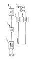
- FIG. 1 shows a block diagram of a conventional stereoscopic display system, and a case where a left and right video signal of 60 Hz is input will be described.
- the left and right video signal of 60 Hz is input to the stereoscopic video processing unit 101, converted into a signal with a period of 120 Hz, and input to the display driving unit 102.
- the display drive unit 102 converts the left and right video signals of 120 Hz into a format that can be displayed on the display display 103 and inputs the converted signal to the display display 103. Thereby, on the display 103, an image is alternately displayed on the left and right with a period of 120 Hz.
- the left glasses position control circuit 104L and the right glasses position control circuit 104R are respectively the left liquid crystal glasses shutter 105L and the right liquid crystal glasses shutter of the stereoscopic observation glasses 105.
- 105R is controlled.
- the eyeglass position control circuits 104 ⁇ / b> L and 104 ⁇ / b> R control the eyeglass shutters 105 ⁇ / b> L and 105 ⁇ / b> R to open and close in synchronization with the left and right output images of the display 103.
- the left and right images that have passed through the eyeglass shutters 105L and 105R are respectively input to the left and right eyes of the person, and as a result, a visual stereoscopic image is generated in the person's head.
- the light from the fluorescent lamp is also incident together with the image from the display display in the room.
- the fluorescent lamp blinks in synchronization with the power supply frequency, and flicker may occur when the blinking period and the period of driving the stereoscopic image observation glasses are in a specific relationship.
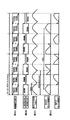
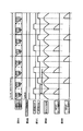
- FIG. 2 is a control timing chart in the conventional stereoscopic display device.
- FIG. 2A shows the scanning timing of the left and right video signals on the display 103
- FIG. 2B shows the opening / closing timing of the eyeglass shutters 105L and 105R
- FIG. 2C shows the temporal change in the light intensity of the fluorescent lamp around the apparatus
- FIG. Indicates the light intensities of the fluorescent lamps passing through the eyeglass shutters 105L and 105R, respectively.
- the fluorescent lamp in the area where the commercial power frequency is 50 Hz has a full-wave rectified waveform whose light intensity is 50 Hz.
- the waveform is repeated with a period of 100 Hz.
- the result obtained by integrating the light intensity waveform of the 100 Hz fluorescent lamp and the shutter opening / closing timing of the 60 Hz glasses is the glasses shutter 105L in FIG. 2D. , 105R, respectively.
- the waveform of FIG. 2D the waveform has a period of 20 Hz. Since the frequency component of this waveform is perceived by the eye as flicker, it interferes.
- this method is obtained by adding a left eyeglass pulse width control circuit 141L and a right eyeglass pulse width control circuit 141R to the conventional example shown in FIG.
- the width of the open period when the glasses are basically opened (light transmission) is adjusted to the fluorescent lamp cycle time (10 msec) of 100 Hz.
- the width of the closed period when the glasses are closed (light shielding) is adjusted to the remaining time (6.7 msec) of the cycle time (16.7 msec) of the glasses at 60 Hz.
- the glasses open period coincides with the periodic period of the light intensity waveform of the 100 Hz fluorescent lamp, so that no flicker occurs.
- Patent Document 2 has the following problems.
- the open period is set to 10 msec by matching the period in which the open periods overlap with the blanking period in which there is no effective video of the other video (left field video if right, right field video if left). The interference between both crosstalk and flicker is reduced in a balanced manner.
- the flicker reduction method may not provide a sufficient flicker reduction effect depending on the length of the blanking period.
- the shutter open period is set to be long, there is a problem that crosstalk interference becomes large.
- An object of the present invention is to provide a stereoscopic display device and a stereoscopic display system capable of reducing flicker due to the influence of a fluorescent lamp while preventing an increase in crosstalk.
- a first stereoscopic display device includes a display control unit that displays a left-eye video and a right-eye video based on an input left-eye video signal and a right-eye video signal on a display unit. And a shutter control unit that controls an open / close state of the left and right shutters of the stereoscopic image observation glasses with an open / close cycle corresponding to a display cycle of the left-eye video and the right-eye video, and the shutter control unit
- the duty ratio of the open period of each of the shutters is controlled to a value greater than 50%, and the display control unit is only while the shutter control unit is controlling one of the left and right shutters to be closed.
- the video image on the side where the shutter is open is displayed among the video for the left eye and the video for the right eye.
- the second stereoscopic display device modulates light incident from the back according to the input left-eye video signal and right-eye video signal, and displays the left-eye video and the right-eye video.
- a liquid crystal panel a backlight that irradiates light from the back to the liquid crystal panel, a backlight control unit that controls a light emission state of the backlight, and an open / closed state of the left and right shutters of the stereoscopic image observation glasses.
- a shutter control unit that controls the open / close cycle according to the display cycle of the right-eye video image, wherein the shutter control unit controls the duty ratio of the open period of each of the left and right shutters to a value greater than 50%.
- the backlight control unit is in an ON state only while the shutter control unit is controlling one of the left and right shutters to be in a closed state. It is controlled to be, a configuration.
- the third stereoscopic display device modulates light incident from the back according to the input left-eye video signal and right-eye video signal, and displays the left-eye video and the right-eye video.
- a shutter control unit that controls with a switching cycle according to the display cycle of the right-eye video
- a flicker detection unit that detects the presence or absence of flicker due to interference between the luminance fluctuation cycle of the ambient light of the device and the switching cycle
- the fourth stereoscopic display device modulates light incident from the back according to the input left-eye video signal and right-eye video signal, and displays the left-eye video and the right-eye video.
- a shutter control unit that controls the open / close cycle according to the display cycle of the right-eye image, and the open period width of each of the left and right shutters is substantially the same as the luminance fluctuation cycle of the ambient light of the device itself,
- the backlight control unit controls the light emission of the backlight to be on only while the shutter control unit is controlling one of the left and right shutters to be closed.
- the fifth stereoscopic display device modulates light incident from the back according to the input left-eye video signal and right-eye video signal, and displays the left-eye video and the right-eye video.
- a liquid crystal panel a backlight that irradiates light from the back to the liquid crystal panel, a backlight control unit that controls a light emission state of the backlight, and an open / closed state of the left and right shutters of the stereoscopic image observation glasses.
- a shutter control unit that controls the open / close cycle according to the display cycle of the right-eye image, and the open period width of each of the left and right shutters is 1 ⁇ 2 of the cycle of the commercial power supply voltage supplied to the device.
- the backlight control unit is configured so that the backlight is turned on only while the shutter control unit is controlling one of the left and right shutters to the closed state. Controlled to so that, a configuration.
- the stereoscopic display system includes the stereoscopic display device, and stereoscopic image observation glasses that are controlled by the stereoscopic display device according to the left-eye video and the right-eye video according to the open / closed state of the left and right shutters, The structure with is adopted.
- the stereoscopic display device and the stereoscopic display system of the present invention it is possible to provide a stereoscopic display device and a stereoscopic display system that can reduce flicker due to the influence of a fluorescent lamp while preventing an increase in crosstalk.
- Block diagram of a conventional stereoscopic display system 2A is a control timing chart in a conventional stereoscopic display device
- FIG. 2A is a diagram showing the scanning timing of the left and right video signals
- FIG. 2B is a diagram showing the opening / closing timing of the glasses shutter
- FIG. 2C is the light intensity of the fluorescent lamp around the device.
- Fig. 2D shows the light intensity of the light passing through the shutter
- Block diagram of a conventional stereoscopic display system that improves flicker 1 is a block diagram illustrating a configuration of a stereoscopic display system according to Embodiment 1.
- FIG. 5A is a control timing chart of the stereoscopic display system
- FIG. 5A is a diagram showing the scanning timing of the left and right video signals
- FIG. 5B is a diagram showing the timing of the light emission on / off control of the backlight and the light emission period
- FIG. FIG. 5D is a diagram showing the light intensity of the fluorescent lamp around the apparatus
- FIG. 5E is a diagram showing the light intensity of the light passing through the shutter.
- 6A is a control timing chart of the stereoscopic display system when a fluorescent tube is used for the backlight
- FIG. 6A is a diagram showing the scanning timing of the left and right video signals
- FIG. 6B is a diagram showing the timing of light emission on / off control of the backlight and the light emission period
- 6C is a diagram showing the opening / closing timing of the shutter
- FIG. 6D is a diagram showing the light intensity of the fluorescent lamp around the apparatus
- FIG. 6E is a diagram showing the light intensity of the light passing through the shutter.
- FIG. 6 is a block diagram illustrating a configuration of a stereoscopic display system according to Embodiment 2.
- 8A is a control timing chart of the stereoscopic display system when the power supply frequency is 60 Hz and there is no flicker
- FIG. 8A is a diagram showing the scanning timing of the left and right video signals
- FIG. 8B is a diagram showing the timing of the light emission on / off control of the backlight and the light emission period.
- FIG. 8C is a diagram showing the opening / closing timing of the shutter
- FIG. 8D is a diagram showing the light intensity of the fluorescent lamp around the apparatus
- FIG. 8E is a diagram showing the light intensity of the light passing through the shutter.
- FIG. 8A is a control timing chart of the stereoscopic display system when the power supply frequency is 60 Hz and there is no flicker
- FIG. 8A is a diagram showing the scanning timing of the left and right
- FIG. 9A is a control timing chart when the power frequency is 50 Hz and the brightness of the first and second peaks in the fluorescent lamp is different.
- FIG. 9A is a diagram showing the scanning timing of the left and right video signals
- FIG. 9B is the timing of backlight emission on / off control.
- FIG. 9C is a diagram showing the opening / closing timing of the shutter
- FIG. 9D is a diagram showing the light intensity of the fluorescent lamp around the apparatus
- FIG. 9E is a diagram showing the light intensity of the light passing through the shutter.
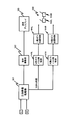
- FIG. 4 is a block diagram illustrating a configuration of the stereoscopic display system according to Embodiment 1.
- the stereoscopic display system 100 includes a stereoscopic display device 10 and stereoscopic image observation glasses 5 that are controlled by the stereoscopic display device 10 in accordance with the left-eye video and the right-eye video.
- the stereoscopic display device 10 includes a stereoscopic video processing unit 1, a liquid crystal driving unit 2, a liquid crystal panel 31, a backlight 32, a shutter control unit 4, and a backlight control unit 6.
- the stereoscopic video processing unit 1 inputs left and right video signals having a basic vertical synchronization frequency. Then, the stereoscopic video processing unit 1 divides and outputs the left-eye video signal and the right-eye video signal at a frequency N times the basic vertical synchronization frequency (N is a positive integer of 1 or more).
- N is a positive integer of 1 or more.
- the input 60 Hz left and right video signals are input and converted into signals with a period of 120 Hz, and the liquid crystal drive unit 2, shutter control unit 4 and backlight control are performed. Output to unit 6.
- the liquid crystal drive unit 2 converts the 120 Hz left and right video signals into a format that can be displayed on the liquid crystal panel 31.
- the liquid crystal drive unit 2 inputs the converted left and right video signals to the liquid crystal panel 31.
- the liquid crystal panel 31 modulates light incident from the back according to the input left-eye video signal and right-eye video signal, and sequentially displays the left-eye video and the right-eye video.
- the liquid crystal panel 31 can employ various driving methods such as an IPS (In Plane Switching) method, a VA (Vertical Alignment) method, and a TN (Twisted Nematic) method.
- the backlight 32 irradiates the liquid crystal panel 31 with light from the back side.
- a backlight that emits light by using a plurality of light emitting diodes arranged two-dimensionally can be used.
- the backlight 32 may obtain surface emission by arranging a plurality of fluorescent tubes side by side.
- the backlight 32 may be of an edge type in which a light emitting diode or a fluorescent tube is arranged at the end.
- the backlight 32 emits light based on the light emission control signal from the backlight control unit 6 based on the synchronization of 120 Hz output from the stereoscopic video processing unit 1.
- the shutter control unit 4 controls the open / close state of the left and right shutters of the stereoscopic image observation glasses 5 with an open / close cycle corresponding to the display cycle of the left-eye video and the right-eye video.
- the shutter control unit 4 controls the open / close state in accordance with the display cycle 120 Hz of the left-eye video and the right-eye video, and therefore controls the open / close cycle 60 Hz.
- the shutter control unit 4 includes a left glasses position control circuit 40L, a right glasses position control circuit 40R, a left glasses pulse width control circuit 41L, and a right glasses pulse width control circuit 41R.
- the left and right eyeglass pulse width control circuits 41L and 41R determine the pulse widths of the open periods of the left and right shutters 5L and 5R based on the synchronization of 120 Hz of the stereoscopic image processing unit 1.
- the left and right eyeglass position control circuits 40L and 40R receive the output signals of the eyeglass pulse width control circuits 41L and 41R, and determine the phase of the shutter opening period. And the open / closed state of the left and right shutters 5L, 5R is controlled by the output signals of the eyeglass position control circuits 40L, 40R.
- the shutter control unit 4 first sets a shutter pulse width (open period width) where flicker hardly occurs so that flicker does not occur even in a fluorescent lamp having a commercial power supply frequency of 50 Hz.
- a shutter pulse width open period width
- this pulse width is set to 10 msec.
- the backlight control unit 6 determines the lighting period (ON period) of the backlight.
- the glasses position control circuit 40L controls based on the output of the backlight control unit 6 so that the left shutter 5L is always closed during the period in which the backlight 32 is lit in response to the right-eye video signal.
- the glasses position control circuit 40R controls based on the output of the backlight control unit 6 so that the right shutter 5R is always closed during the period in which the backlight 32 is lit corresponding to the left-eye video signal. .
- FIG. 5 shows a control timing chart of the stereoscopic display system 100.
- FIG. 5A shows the scanning timing of the left and right video signals on the liquid crystal panel 31
- FIG. 5B shows the timing of the light emission on / off control of the backlight 32 and the light emission period of the backlight 32 by the backlight control unit 6
- FIG. 5L and 5R show the opening / closing timing of 5L and 5R
- FIG. 5D shows the time change of the light intensity of the fluorescent lamp around the apparatus
- FIG. 5E shows the light intensity of the fluorescent lamp passing through the shutters 5L and 5R, respectively.
- the power supply frequency is 50 Hz
- the light intensity of the fluorescent lamp has a waveform peak period of 100 Hz (10 msec) as shown in FIG. 5D.
- the width of the open period of the left and right shutters 5L and 5R of the glasses is set to 10 msec as described above.
- the left-eye shutter 5L is controlled to be closed, and the backlight corresponding to the left-eye video signal is controlled.
- the right-eye shutter 5R is controlled to be in the closed period. Therefore, the occurrence of crosstalk between the left and right images can be suppressed.
- the shutter control unit 4 is configured to control the open / close state of the left and right shutters 5L and 5R so that the open periods of the left and right shutters 5L and 5R are 10 msec. That is, the open period widths of the left and right shutters 5L and 5R substantially coincide with the luminance fluctuation period of the ambient light of the stereoscopic display device 10.
- substantially match means that, for example, 90 or more matches. As a result, flicker can be minimized.
- the open period widths of the left and right shutters 5L and 5R substantially coincide with 1 ⁇ 2 of the cycle of the commercial power supply voltage supplied to the stereoscopic display device 10.
- the amounts of peripheral light incident during the open periods of the left and right shutters 5L and 5R are substantially the same, and flicker can be minimized.
- the control of the shutter control unit 4 is not limited to these.
- the shutter control unit 4 can obtain a flicker reduction effect more than that of the conventional stereoscopic display device by controlling the duty ratio of the open periods of the left and right shutters 5L and 5R to a value larger than 50%. If the duty ratio of the open periods of the left and right shutters 5L and 5R is greater than 50%, the shutter open periods overlap.
- the backlight control unit 6 controls the light emission of the backlight 32 to be on only while the shutter control unit 4 controls either one of the left and right shutters 5L and 5R to the closed state. The occurrence of crosstalk can be suppressed.
- FIG. 6 shows a control timing chart of the stereoscopic display system 100 when a fluorescent tube is used for the backlight 32.
- the backlight control unit 6 prevents the afterglow after turning off the light emission of the backlight 32 from leaking during a period in which both the left and right shutters 5R and 5L are open. Controls the light emission state.
- the control time of the backlight 32 and the lighting time of the backlight 32 are not the same, and the lighting time of the backlight 32 becomes longer. Further, this afterglow generally has the longest G (Green). Therefore, by controlling the ON period of the backlight 32 including the afterglow to be included in the closed period of the shutters 5R and 5L, not only crosstalk but also color unevenness can be suppressed.
- the second embodiment is different from the first embodiment in that it mainly includes a flicker detection unit that detects flicker.
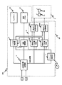
- FIG. 7 is a block diagram showing a configuration of the stereoscopic display system 200 according to the second embodiment.
- the stereoscopic display system 200 includes a stereoscopic display device 20 and stereoscopic image observation glasses 5 that are controlled by the stereoscopic display device 20 in accordance with the left-eye video and the right-eye video.
- the stereoscopic display device 20 includes a stereoscopic video processing unit 1, a liquid crystal drive unit 2, a liquid crystal panel 31, a backlight 32, a flicker detection unit 7, a shutter control unit 8, and a backlight control unit 9.
- the flicker detection unit 7 detects the presence or absence of flicker due to interference between the luminance fluctuation cycle of the ambient light of the stereoscopic display device 20 and the shutter opening / closing cycle. For example, it may be determined that the flicker is present when the amplitude of the flicker is greater than or equal to a predetermined value, and may be determined that there is no flicker when the amplitude is smaller than the predetermined value.
- the flicker detection unit 7 inputs a synchronization signal having a frequency of 120 Hz in the left and right video signals and ambient light from the fluorescent lamp, and detects flicker of the fluorescent lamp in the 50 Hz power supply frequency region.
- the shutter control unit 8 controls the duty ratio of the open periods of the left and right shutters 5L and 5R with a value larger than 50%. Further, when flicker is not detected, the shutter control unit 8 controls the duty ratios of the open periods of the left and right shutters 5L and 5R with values of 50% or less.
- the backlight control unit 9 emits the backlight only while the shutter control unit 8 controls one of the left and right shutters 5L and 5R to be closed. Control to turn on.
- the backlight control unit 9 performs control so that the light emission of the backlight 32 is always on when the flicker detection unit 7 does not detect flicker.
- FIG. 8 shows a control timing chart of the stereoscopic display system 200 when the power supply frequency is 60 Hz and the flicker detection unit 7 does not detect flicker.
- the pulse width of the shutters 5R and 5L is adjusted to 1/120 second or less (8.35 msec or less) and the luminance is maximized.
- the ON period of the backlight 32 is adjusted so that the crosstalk can be optimized.
- the open periods of the shutters 5L and 5R do not overlap, and crosstalk can be suppressed.
- the following effects can be obtained by switching the control depending on whether or not flicker is detected.
- flicker When flicker is detected, the shutter open period is extended to reduce flicker and the backlight emission timing is controlled to prevent the occurrence of crosstalk.
- the shutter opening period is shortened to prevent the occurrence of crosstalk, the backlight is always turned on to increase the brightness, or the temperature of the liquid crystal panel 31 is increased to increase the response. It can be raised.
- the backlight control unit 9 controls the light emission of the backlight 32 to be always on when the flicker is not detected by the flicker detection unit 7. I can't. When the flicker is not detected by the flicker detection unit 7, the light emission of the backlight 32 is turned on only while the shutter control unit 9 controls one of the left and right shutters 5L and 5R to the open state. You may control to. In this way, low power consumption can be achieved.
- the method for detecting the presence or absence of flicker is not limited to the above.
- the presence or absence of flicker may be detected by determining that there is flicker when the power supply frequency of the stereoscopic display device is 50 Hz and that there is no flicker when the power supply frequency is 60 Hz.
- Embodiment 3 of the present invention will be described with reference to the drawings.
- the third embodiment is different from the first and second embodiments in that flicker is further reduced when there is an asymmetry in the amplitude of the emission luminance of a full-wave rectified fluorescent lamp.
- the configuration of the block diagram of the second embodiment is almost the same.
- the power supply frequency is 50 Hz
- the light emitted from the full-wave rectified fluorescent lamp does not have a 100 Hz period, and the first and second peaks are different from each other due to the rectifier circuit, resulting in 50 Hz.
- the flicker detection unit detects the flicker cycle due to the interference between the luminance fluctuation cycle of the ambient light of the device itself and the shutter opening / closing cycle.
- the shutter control unit controls the width of the open period or the closed period of the left and right shutters based on the flicker cycle.
- FIG. 9 shows a control timing chart when the brightness of the first and second peaks in a fluorescent lamp with a power frequency of 50 Hz is different.
- FIG. 9D shows the light intensity of the fluorescent lamp.
- the shutter control unit 9 controls the open / close state of the left and right shutters 5L and 5R so that the flicker is reduced. Specifically, flicker can be further improved by controlling the open periods of the shutters 5L and 5R according to the detected flicker cycle.
- the liquid crystal panel is an example of a display unit.
- the backlight and the backlight control unit are examples of the display control unit.
- an organic EL panel, a plasma display panel, or the like may be applied as the display unit as long as the display unit includes a display control unit that can control the display timing of the video displayed on the display unit.
- the present invention is suitable as a stereoscopic display device and a stereoscopic display system capable of reducing crosstalk and reducing flicker.
Landscapes
- Engineering & Computer Science (AREA)
- Multimedia (AREA)
- Signal Processing (AREA)
- Physics & Mathematics (AREA)
- General Physics & Mathematics (AREA)
- Optics & Photonics (AREA)
- Liquid Crystal Display Device Control (AREA)
- Testing, Inspecting, Measuring Of Stereoscopic Televisions And Televisions (AREA)
- Control Of Indicators Other Than Cathode Ray Tubes (AREA)
Abstract
Description
図4は、実施の形態1に係る立体表示システムの構成を示すブロック図である。立体表示システム100は、立体表示装置10と、立体表示装置10によって左右のシャッター5L、5Rの開閉状態を左目用映像と右目用映像に合わせて制御される立体画像観察用眼鏡5とからなる。
次に本発明の実施の形態2について、図面を参照しながら説明する。実施の形態2は、主として、フリッカを検出するフリッカ検出部を有する点で、実施の形態1とは異なる。
次に本発明の実施の形態3について、図面を参照しながら説明する。実施の形態3は、全波整流された蛍光灯の発光輝度の振幅に非対称性が存在する場合のフリッカをさらに低減する点で、実施の形態1および2とは異なる。
2 液晶駆動部
31 液晶パネル
32 バックライト
4、8 シャッター制御部
40L、80L、104L 左側メガネ位置制御回路
40R、80R、104R 右側メガネ位置制御回路
41L、81L、141L 左側メガネパルス幅制御回路
41R、81R、141R 右側メガネパルス幅制御回路
5、105 立体画像観察用眼鏡
5L、105L 左シャッター
5R、105R 右シャッター
6、9 バックライト制御部
7 フリッカ検出部
10、20 立体表示装置
100、200 立体表示システム
102 表示駆動部
103 表示ディスプレイ
Claims (12)
- 入力される左目用映像信号と右目用映像信号に基づく左目用映像と右目用映像とを表示部に表示させる表示制御部と、
立体画像観察用眼鏡の左右のシャッターの開閉状態を前記左目用映像と右目用映像の表示周期に応じた開閉周期で制御するシャッター制御部と、を備え、
前記シャッター制御部は、前記左右のシャッターそれぞれの開期間のデューティ比を50%よりも大きい値で制御し、
前記表示制御部は、前記シャッター制御部が前記左右のシャッターのいずれか一方を閉状態に制御している間にのみ、前記映像左目用映像と右目用映像のうちシャッターが開状態である側の映像を表示させる、
立体表示装置。 - 入力される左目用映像信号と右目用映像信号とに応じて背面から入射する光を変調し、左目用映像と右目用映像とを表示する液晶パネルと、
前記液晶パネルに背面から光を照射するバックライトと、
前記バックライトの発光状態を制御するバックライト制御部と、
立体画像観察用眼鏡の左右のシャッターの開閉状態を前記左目用映像と右目用映像の表示周期に応じた開閉周期で制御するシャッター制御部と、を備え、
前記シャッター制御部は、前記左右のシャッターそれぞれの開期間のデューティ比を50%よりも大きい値で制御し、
前記バックライト制御部は、前記シャッター制御部が前記左右のシャッターのいずれか一方を閉状態に制御している間にのみ前記バックライトの発光がオン状態となるように制御する、
立体表示装置。 - 入力される左目用映像信号と右目用映像信号とに応じて背面から入射する光を変調し、左目用映像と右目用映像とを表示する液晶パネルと、
前記液晶パネルに背面から光を照射するバックライトと、
前記バックライトの発光状態を制御するバックライト制御部と、
立体画像観察用眼鏡の左右のシャッターの開閉状態を前記左目用映像と右目用映像の表示周期に応じた開閉周期で制御するシャッター制御部と、
自装置の周辺光の輝度変動周期と前記開閉周期の干渉によるフリッカの有無を検出するフリッカ検出部と、を備え、
前記シャッター制御部は、前記フリッカ検出部でフリッカが検出された場合、前記左右のシャッターそれぞれの開期間のデューティ比を50%よりも大きい値で制御し、
前記バックライト制御部は、前記フリッカ検出部でフリッカが検出された場合、前記シャッター制御部が前記左右のシャッターのいずれか一方を閉状態に制御している間にのみ前記バックライトの発光がオン状態となるように制御する、
立体表示装置。 - 前記シャッター制御部は、前記フリッカ検出部でフリッカが検出されなかった場合、前記左右のシャッターそれぞれの開期間のデューティ比を50%以下の値で制御する、
請求項3記載の立体表示装置。 - 前記バックライト制御部は、前記フリッカ検出部でフリッカが検出されなかった場合、前記バックライトの発光が常時オン状態となるように制御する、
請求項3記載の立体表示装置。 - 前記バックライト制御部は、前記フリッカ検出部でフリッカが検出されなかった場合、前記シャッター制御部が前記左右のシャッターのいずれか一方を開状態に制御している間にのみ前記バックライトの発光がオン状態となるように制御する、
請求項3記載の立体表示装置。 - 前記バックライト制御部は、前記バックライトの発光をオフ状態にした後の残光が前記左右のシャッターの両方が開状態となる期間に漏れ込まないように前記バックライトの発光状態を制御する、
請求項2記載の立体表示装置。 - 前記バックライト制御部は、前記バックライトの発光をオフ状態にした後の残光が前記左右のシャッターの両方が開状態となる期間に漏れ込まないように前記バックライトの発光状態を制御する、
請求項3記載の立体表示装置。 - 自装置の周辺光の輝度変動周期と前記開閉周期の干渉によるフリッカの周期を検出するフリッカ検出部を備え、
前記シャッター制御部は、前記フリッカの周期に基づいて、前記左右のシャッターの開期間の幅または閉期間の幅を制御する、
請求項1記載の立体表示装置。 - 入力される左目用映像信号と右目用映像信号とに応じて背面から入射する光を変調し、左目用映像と右目用映像とを表示する液晶パネルと、
前記液晶パネルに背面から光を照射するバックライトと、
前記バックライトの発光状態を制御するバックライト制御部と、
立体画像観察用眼鏡の左右のシャッターの開閉状態を前記左目用映像と右目用映像の表示周期に応じた開閉周期で制御するシャッター制御部と、を備え、
前記左右のシャッターそれぞれの開期間幅は、自装置の周辺光の輝度変動周期と略一致しており、
前記バックライト制御部は、前記シャッター制御部が前記左右のシャッターのいずれか一方を閉状態に制御している間にのみ前記バックライトの発光がオン状態となるように制御する、
立体表示装置。 - 入力される左目用映像信号と右目用映像信号とに応じて背面から入射する光を変調し、左目用映像と右目用映像とを表示する液晶パネルと、
前記液晶パネルに背面から光を照射するバックライトと、
前記バックライトの発光状態を制御するバックライト制御部と、
立体画像観察用眼鏡の左右のシャッターの開閉状態を前記左目用映像と右目用映像の表示周期に応じた開閉周期で制御するシャッター制御部と、を備え、
前記左右のシャッターそれぞれの開期間幅は、自装置に供給される商用電源電圧の周期の1/2に略一致しており、
前記バックライト制御部は、前記シャッター制御部が前記左右のシャッターのいずれか一方を閉状態に制御している間にのみ前記バックライトの発光がオン状態となるように制御する、
立体表示装置。 - 請求項1記載の立体表示装置と、
前記立体表示装置によって左右のシャッターの開閉状態を前記左目用映像と右目用映像に合わせて制御される立体画像観察用眼鏡と、を備えた、
立体表示システム。
Priority Applications (4)
| Application Number | Priority Date | Filing Date | Title |
|---|---|---|---|
| JP2011517129A JP5275461B2 (ja) | 2009-11-02 | 2010-11-01 | 立体表示装置および立体表示システム |
| EP10826371A EP2498505A1 (en) | 2009-11-02 | 2010-11-01 | Three-dimensional display apparatus and three-dimensional display system |
| CN2010800033433A CN102227914A (zh) | 2009-11-02 | 2010-11-01 | 立体显示装置以及立体显示系统 |
| US13/132,037 US20110234777A1 (en) | 2009-11-02 | 2010-11-01 | Three-demensional display apparatus and three-dimensional display system |
Applications Claiming Priority (2)
| Application Number | Priority Date | Filing Date | Title |
|---|---|---|---|
| JP2009-251688 | 2009-11-02 | ||
| JP2009251688 | 2009-11-02 |
Publications (1)
| Publication Number | Publication Date |
|---|---|
| WO2011052236A1 true WO2011052236A1 (ja) | 2011-05-05 |
Family
ID=43921668
Family Applications (1)
| Application Number | Title | Priority Date | Filing Date |
|---|---|---|---|
| PCT/JP2010/006443 Ceased WO2011052236A1 (ja) | 2009-11-02 | 2010-11-01 | 立体表示装置および立体表示システム |
Country Status (5)
| Country | Link |
|---|---|
| US (1) | US20110234777A1 (ja) |
| EP (1) | EP2498505A1 (ja) |
| JP (1) | JP5275461B2 (ja) |
| CN (1) | CN102227914A (ja) |
| WO (1) | WO2011052236A1 (ja) |
Cited By (3)
| Publication number | Priority date | Publication date | Assignee | Title |
|---|---|---|---|---|
| WO2012046424A1 (ja) * | 2010-10-04 | 2012-04-12 | パナソニック株式会社 | 映像表示装置 |
| JP2012085260A (ja) * | 2010-09-14 | 2012-04-26 | Panasonic Corp | 情報表示装置、再生装置、および立体映像表示装置 |
| WO2015097742A1 (ja) * | 2013-12-24 | 2015-07-02 | 株式会社 東芝 | 立体映像表示装置 |
Families Citing this family (12)
| Publication number | Priority date | Publication date | Assignee | Title |
|---|---|---|---|---|
| WO2012081181A1 (ja) * | 2010-12-13 | 2012-06-21 | パナソニック株式会社 | 眼鏡装置及び眼鏡装置の制御方法 |
| US9426453B2 (en) * | 2011-03-04 | 2016-08-23 | Dolby Laboratories Licensing Corporation | Methods and apparatus for 3D shutter glasses synchronization |
| KR101906424B1 (ko) * | 2011-11-15 | 2018-12-10 | 엘지디스플레이 주식회사 | 이원 방식 홀로그래피 입체 영상 표시장치 |
| CN102547341A (zh) * | 2011-12-20 | 2012-07-04 | 四川长虹电器股份有限公司 | 一种调整电视机3d眼镜镜片开通时间的方法 |
| WO2013092198A1 (en) * | 2011-12-20 | 2013-06-27 | Sony Corporation | Tv frame play-out in sync with line cycle |
| US9413982B2 (en) | 2012-02-28 | 2016-08-09 | Hewlett-Packard Development Company, L.P. | System and method for video frame sequence control |
| CN102663981A (zh) * | 2012-04-19 | 2012-09-12 | 深圳市华星光电技术有限公司 | 立体显示装置及其显示控制方法 |
| JP5950692B2 (ja) * | 2012-05-25 | 2016-07-13 | 三菱電機株式会社 | 立体画像表示装置 |
| US9513507B2 (en) * | 2013-12-30 | 2016-12-06 | Shenzhen China Star Optoelectronics Technology Co., Ltd. | Three-dimensional liquid crystal display device, and shutter glass and control method for the same |
| US10459224B2 (en) * | 2014-09-29 | 2019-10-29 | Honeywell International Inc. | High transmittance eyewear for head-up displays |
| US9606355B2 (en) | 2014-09-29 | 2017-03-28 | Honeywell International Inc. | Apparatus and method for suppressing double images on a combiner head-up display |
| CN107272319A (zh) * | 2016-04-07 | 2017-10-20 | 中强光电股份有限公司 | 投影装置以及影像投影方法 |
Citations (5)
| Publication number | Priority date | Publication date | Assignee | Title |
|---|---|---|---|---|
| JPS62133891A (ja) | 1985-12-06 | 1987-06-17 | Victor Co Of Japan Ltd | 画像再生装置 |
| JPS6486694A (en) * | 1987-09-28 | 1989-03-31 | Sharp Kk | Stereoscopic video reproducing system |
| JPH09138384A (ja) | 1995-11-15 | 1997-05-27 | Sanyo Electric Co Ltd | 立体画像観察用眼鏡の制御方法 |
| WO2008056753A1 (en) * | 2006-11-08 | 2008-05-15 | Nec Corporation | Display system |
| JP2009251688A (ja) | 2008-04-01 | 2009-10-29 | Canon Inc | 構造化データ処理装置、方法及びプログラム |
Family Cites Families (15)
| Publication number | Priority date | Publication date | Assignee | Title |
|---|---|---|---|---|
| US5402191A (en) * | 1992-12-09 | 1995-03-28 | Imax Corporation | Method and apparatus for presenting stereoscopic images |
| TW432354B (en) * | 1999-03-16 | 2001-05-01 | Asustek Comp Inc | The control device of LCD shutter glass |
| KR100381963B1 (ko) * | 2000-12-26 | 2003-04-26 | 삼성전자주식회사 | 감소된 플리커를 갖는 액정 표시 장치 및 그것의 플리커저감 방법 |
| TW548960B (en) * | 2001-01-23 | 2003-08-21 | Vrex Inc | Method and apparatus of flicker reduction for LC shutter glasses |
| JP4354449B2 (ja) * | 2005-10-26 | 2009-10-28 | オリンパス株式会社 | 表示画像撮像方法および装置 |
| JP4438826B2 (ja) * | 2007-06-04 | 2010-03-24 | セイコーエプソン株式会社 | プロジェクタ及びプロジェクタ用光源装置の駆動方法 |
| CN101415126A (zh) * | 2007-10-18 | 2009-04-22 | 深圳Tcl新技术有限公司 | 一种产生三维图像效果的方法及数字视频装置 |
| CN101878654B (zh) * | 2007-11-28 | 2013-02-13 | 皇家飞利浦电子股份有限公司 | 立体可视化 |
| JP5111100B2 (ja) * | 2007-12-28 | 2012-12-26 | キヤノン株式会社 | 画像処理装置、画像処理方法、プログラム及び記憶媒体 |
| TWI383709B (zh) * | 2008-02-21 | 2013-01-21 | Chunghwa Picture Tubes Ltd | 光源驅動模組及電路 |
| JP4518283B2 (ja) * | 2008-03-19 | 2010-08-04 | セイコーエプソン株式会社 | 放電灯点灯装置及びその制御方法並びにプロジェクタ |
| KR101362771B1 (ko) * | 2008-09-17 | 2014-02-14 | 삼성전자주식회사 | 입체 영상 표시 방법 및 장치 |
| JP2011053554A (ja) * | 2009-09-03 | 2011-03-17 | Toshiba Mobile Display Co Ltd | 有機el表示装置 |
| US20110090324A1 (en) * | 2009-10-15 | 2011-04-21 | Bit Cauldron Corporation | System and method of displaying three dimensional images using crystal sweep with freeze tag |
| JP5214020B2 (ja) * | 2009-12-07 | 2013-06-19 | パナソニック株式会社 | 立体表示システム |
-
2010
- 2010-11-01 EP EP10826371A patent/EP2498505A1/en not_active Withdrawn
- 2010-11-01 CN CN2010800033433A patent/CN102227914A/zh active Pending
- 2010-11-01 WO PCT/JP2010/006443 patent/WO2011052236A1/ja not_active Ceased
- 2010-11-01 US US13/132,037 patent/US20110234777A1/en not_active Abandoned
- 2010-11-01 JP JP2011517129A patent/JP5275461B2/ja not_active Expired - Fee Related
Patent Citations (5)
| Publication number | Priority date | Publication date | Assignee | Title |
|---|---|---|---|---|
| JPS62133891A (ja) | 1985-12-06 | 1987-06-17 | Victor Co Of Japan Ltd | 画像再生装置 |
| JPS6486694A (en) * | 1987-09-28 | 1989-03-31 | Sharp Kk | Stereoscopic video reproducing system |
| JPH09138384A (ja) | 1995-11-15 | 1997-05-27 | Sanyo Electric Co Ltd | 立体画像観察用眼鏡の制御方法 |
| WO2008056753A1 (en) * | 2006-11-08 | 2008-05-15 | Nec Corporation | Display system |
| JP2009251688A (ja) | 2008-04-01 | 2009-10-29 | Canon Inc | 構造化データ処理装置、方法及びプログラム |
Cited By (4)
| Publication number | Priority date | Publication date | Assignee | Title |
|---|---|---|---|---|
| JP2012085260A (ja) * | 2010-09-14 | 2012-04-26 | Panasonic Corp | 情報表示装置、再生装置、および立体映像表示装置 |
| WO2012046424A1 (ja) * | 2010-10-04 | 2012-04-12 | パナソニック株式会社 | 映像表示装置 |
| US9438892B2 (en) | 2010-10-04 | 2016-09-06 | Panasonic Intellectual Property Management Co., Ltd. | Video display device |
| WO2015097742A1 (ja) * | 2013-12-24 | 2015-07-02 | 株式会社 東芝 | 立体映像表示装置 |
Also Published As
| Publication number | Publication date |
|---|---|
| EP2498505A1 (en) | 2012-09-12 |
| JP5275461B2 (ja) | 2013-08-28 |
| US20110234777A1 (en) | 2011-09-29 |
| JPWO2011052236A1 (ja) | 2013-03-14 |
| CN102227914A (zh) | 2011-10-26 |
Similar Documents
| Publication | Publication Date | Title |
|---|---|---|
| JP5275461B2 (ja) | 立体表示装置および立体表示システム | |
| JP5556492B2 (ja) | 電気光学装置および立体視表示装置 | |
| JP5558163B2 (ja) | 立体映像表示装置及びその駆動方法 | |
| US9001198B2 (en) | Image display viewing system, optical modulator and image display device | |
| JPWO2011142141A1 (ja) | 表示装置及び映像視聴システム | |
| JP2011128548A (ja) | 画像表示装置、画像表示観察システム及び画像表示方法 | |
| US20110292089A1 (en) | Display device, display method and computer program | |
| JP2011252943A (ja) | 立体表示システム | |
| JP5214020B2 (ja) | 立体表示システム | |
| TWI423223B (zh) | 液晶顯示裝置及其背光調整方法 | |
| US20110221788A1 (en) | Liquid crystal display and picture display system | |
| KR101981530B1 (ko) | 입체영상 표시장치와 그 구동방법 | |
| JP5884367B2 (ja) | プロジェクター | |
| CN103439798B (zh) | 立体显示装置驱动方法及设备、立体显示装置及立体眼镜 | |
| JP5400902B2 (ja) | 制御装置、表示装置、眼鏡装置及び映像システム | |
| US9083967B2 (en) | Method for displaying a stereoscopic image and display apparatus for performing the same | |
| US20130002837A1 (en) | Display control circuit and projector apparatus | |
| KR20120095098A (ko) | 입체영상 표시장치 및 그의 크로스토크 보상방법 | |
| KR101291804B1 (ko) | 입체영상 표시장치 | |
| KR101063478B1 (ko) | 안경을 이용한 입체영상 제공 장치 및 그 방법 | |
| EP3990973B1 (en) | Display apparatus and method of controlling thereof | |
| JP2011237687A (ja) | 表示装置及び映像視聴システム | |
| WO2013038883A1 (ja) | 立体画像表示装置、及び立体画像表示装置の駆動方法 | |
| KR101811059B1 (ko) | 입체영상 표시장치 | |
| CN103916651A (zh) | 可平衡左右眼图像亮度的立体图像系统及相关驱动方法 |
Legal Events
| Date | Code | Title | Description |
|---|---|---|---|
| WWE | Wipo information: entry into national phase |
Ref document number: 201080003343.3 Country of ref document: CN |
|
| WWE | Wipo information: entry into national phase |
Ref document number: 2011517129 Country of ref document: JP |
|
| WWE | Wipo information: entry into national phase |
Ref document number: 13132037 Country of ref document: US Ref document number: 2010826371 Country of ref document: EP |
|
| 121 | Ep: the epo has been informed by wipo that ep was designated in this application |
Ref document number: 10826371 Country of ref document: EP Kind code of ref document: A1 |
|
| NENP | Non-entry into the national phase |
Ref country code: DE |