WO2011052276A1 - 画像処理装置、画像処理方法、画像処理プログラム、画像処理プログラムを記録した記録媒体 - Google Patents
画像処理装置、画像処理方法、画像処理プログラム、画像処理プログラムを記録した記録媒体 Download PDFInfo
- Publication number
- WO2011052276A1 WO2011052276A1 PCT/JP2010/063220 JP2010063220W WO2011052276A1 WO 2011052276 A1 WO2011052276 A1 WO 2011052276A1 JP 2010063220 W JP2010063220 W JP 2010063220W WO 2011052276 A1 WO2011052276 A1 WO 2011052276A1
- Authority
- WO
- WIPO (PCT)
- Prior art keywords
- image
- line segment
- quadrilateral
- unit
- virtual line
- Prior art date
- Legal status (The legal status is an assumption and is not a legal conclusion. Google has not performed a legal analysis and makes no representation as to the accuracy of the status listed.)
- Ceased
Links
Images


Classifications
-
- H—ELECTRICITY
- H04—ELECTRIC COMMUNICATION TECHNIQUE
- H04N—PICTORIAL COMMUNICATION, e.g. TELEVISION
- H04N1/00—Scanning, transmission or reproduction of documents or the like, e.g. facsimile transmission; Details thereof
- H04N1/387—Composing, repositioning or otherwise geometrically modifying originals
-
- G—PHYSICS
- G06—COMPUTING OR CALCULATING; COUNTING
- G06T—IMAGE DATA PROCESSING OR GENERATION, IN GENERAL
- G06T5/00—Image enhancement or restoration
- G06T5/80—Geometric correction
-
- G—PHYSICS
- G06—COMPUTING OR CALCULATING; COUNTING
- G06T—IMAGE DATA PROCESSING OR GENERATION, IN GENERAL
- G06T7/00—Image analysis
- G06T7/10—Segmentation; Edge detection
- G06T7/12—Edge-based segmentation
-
- H—ELECTRICITY
- H04—ELECTRIC COMMUNICATION TECHNIQUE
- H04N—PICTORIAL COMMUNICATION, e.g. TELEVISION
- H04N23/00—Cameras or camera modules comprising electronic image sensors; Control thereof
- H04N23/60—Control of cameras or camera modules
- H04N23/68—Control of cameras or camera modules for stable pick-up of the scene, e.g. compensating for camera body vibrations
Definitions
- the present invention relates to an image processing apparatus, and more particularly to an image processing apparatus that corrects image distortion.
- Patent Document 1 Japanese Patent Application Laid-Open No. 8-163427
- Patent Document 2 the original aspect ratio of the subject image and the projection parameters are calculated from the distorted subject image in the captured image. Then, the distortion of the captured image is corrected using them.
- Patent Document 3 distortion of a captured image (document image) is detected using a line segment detected from a document image. It is corrected.
- An object of the present invention is to provide an image processing apparatus capable of correcting distortion of an image of a subject without manually adjusting a correction degree.
- an image processing apparatus generates a line segment image obtained by extracting a contour line segment that is a line segment included in the contour of the subject image from a captured image obtained by capturing the subject.
- an image correction unit that corrects the perspective transformation distortion of the captured image.
- An image processing method is an image processing method in an image processing apparatus for solving the above-described problem, and is a line segment included in an outline of an image of a subject from a captured image obtained by capturing the subject.
- a line segment image generation step for generating a line segment image obtained by extracting a contour line segment, and inserting at least one virtual line segment that is a virtual line segment into the line segment image generated in the line segment image generation step
- a quadrilateral specifying step of selecting four line segments from the set of virtual line segments and the contour line segments, and specifying a quadrilateral surrounded by four straight lines each including the four line segments, and the four sides
- an image correction step of correcting the perspective transformation distortion of the captured image based on the quadrilateral specified in the shape specifying step.
- the line segment image generation unit extracts the contour of the subject image from the captured image obtained by capturing the subject. Then, the line segment image generation unit generates a line segment image indicating the contour line segment by extracting a contour line segment that is a line segment included in the extracted contour (a straight line segment separated by two points).
- the subject includes two sets of line segments that are substantially parallel to each other at the outer edge, and the angle between the sets of line segments that are substantially perpendicular to each other (for example, a subject having a rectangular or square surface). Assumed. Further, it is assumed that the subject image included in the captured image has at least two sides.
- the quadrilateral identifying unit inserts at least one virtual line segment into the generated line segment image, selects four line segments from the set of the inserted virtual line segment and the outline segment included in the line segment image, A quadrilateral surrounded by four straight lines each including the four line segments is specified.
- the image correcting unit corrects the perspective transformation distortion of the captured image based on the quadrilateral identified by the quadrilateral identifying unit.
- the image correction unit may cause the quadrangle to have the same aspect ratio as the aspect ratio of the image of the subject corresponding to the quadrangle so that the four corners of the quadrangle specified by the quadrangle specifying unit are perpendicular to each other.
- the perspective transformation distortion of the captured image is corrected by correcting the quadrilateral.
- the perspective transformation distortion of the captured image can be corrected appropriately.
- the image processing apparatus generates a line segment image that generates a line segment image obtained by extracting a contour line segment that is a line segment included in the contour of the subject image from a captured image obtained by capturing the subject.
- At least one virtual line segment that is a virtual line segment is inserted into the line segment image generated by the generation unit and the line segment image generation unit, and four lines are collected from the set of the inserted virtual line segment and the contour line segment.
- a quadrilateral specifying unit that selects a line segment and specifies a quadrilateral surrounded by four straight lines each including the four line segments, and a quadrilateral specified by the quadrilateral specifying unit, And an image correcting unit that corrects the perspective transformation distortion.
- An image processing method is an image processing method in an image processing apparatus, and extracts a line segment image, which is a line segment included in the outline of the subject image, from a captured image obtained by imaging the subject.
- a line image generating step for generating a line segment, and at least one virtual line segment that is a virtual line segment is inserted into the line segment image generated in the line segment image generating step, and the inserted virtual line segment and the contour line segment are inserted
- an image correction step for correcting the perspective transformation distortion of the captured image.
- the perspective transformation distortion of the captured image can be appropriately corrected.
- FIG. 1 is a block diagram illustrating a configuration of an image processing apparatus according to an embodiment of the present invention. It is a figure for demonstrating the function of the digital camera which concerns on one Embodiment of this invention. It is a block diagram which shows the structure of the digital camera which concerns on one Embodiment of this invention.
- (A) is a figure which shows an example of a captured image
- (b) is a figure which shows the edge image produced
- (A) is a figure which shows an example of the edge image which the outline extraction part produced
- (b) is a figure which shows the line segment image produced
- (A) is a graph showing the positions of point A and point B in the xy coordinate system of the edge image, and (b) converts (x, y) coordinates in the xy coordinate system into coordinates ( ⁇ , ⁇ ) in the polar coordinate system. It is a graph which shows the curve corresponding to the point A and the point B when doing. It is a figure which shows the vote in Hough conversion.
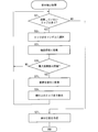
- It is a flowchart which shows an example of the flow of a process in the line segment extraction part with which the said image processing apparatus is provided.
- (A) And (b) is a figure which shows the specific example of the quadrilateral candidate from which evaluation value differs. It is a figure for demonstrating the significance of making the evaluation value of a virtual line segment small. It is a figure which shows the example of a display in the monitor of a captured image and a quadrilateral candidate. It is a figure which shows an example of an operation button. It is a figure which shows the positional relationship of the object in perspective transformation.
- (A) is a figure which shows an example of the image after correction
- (b) is a figure which shows an example of the quadrilateral contained in the image before correction
- FIG. 1 It is a flowchart which shows an example of the flow of a process in the quadrangle candidate calculation part with which the image processing apparatus concerning another embodiment of this invention is provided.
- A is a figure which shows an example of the display screen of a monitor when selecting a virtual line segment
- (b) is a figure which shows the display screen of a monitor when the rightmost virtual line segment is selected. It is a figure which shows an example of the operation button for inputting the insertion position of a virtual line segment.
- (A) And (b) is a figure for demonstrating the insertion position determination process in an insertion position determination part. It is a figure which shows the structure of the computer which concerns on another embodiment of this invention.
- the image processing apparatus of the present invention is not limited to a digital camera, but is an apparatus (for example, a scanner, a printer, a mobile phone) that acquires captured image data from a built-in imaging apparatus or an external apparatus and processes the captured image data. ) As long as it is any device.
- an apparatus for example, a scanner, a printer, a mobile phone
- FIG. 2 is a diagram for explaining functions of the digital camera 100 according to the present embodiment.
- the digital camera 100 captures the white plate 110 from an oblique direction
- the white plate image 112 in the captured image 111 is distorted.
- a subject such as a schedule board
- a part of the subject image may not fit in the captured image.
- an image including a white plate image 114 without distortion such as the corrected image 113 is obtained.
- an image without distortion can be obtained even when a part of the subject image does not fit in the captured image.
- FIG. 3 is a diagram illustrating the configuration of the digital camera 100.
- a digital camera 100 includes an optical system 1, an image sensor 2, a memory 3, a card reader / writer 4, a CPU (central processing unit) 5, an operation button 6, a monitor (display unit) 7, and an image processing device. 10 is provided.
- the optical system 1 includes a lens (not shown) for forming an image of a subject on the imaging surface of the image sensor 2 and a lens driving mechanism (not shown) for adjusting the focus of the lens.
- the optical system 1 outputs focal length information indicating the focal length when the captured image is captured to the CPU 5.
- the image sensor 2 is an image pickup element having an image pickup surface in which a plurality of sensors are arranged in a matrix, and converts an optical image of a subject formed on the image pickup surface through the optical system 1 into an image signal.
- a charge coupled device (CCD) image sensor or a complementary metal-oxide-semiconductor (CMOS) image sensor can be used.
- the image sensor 2 stores the generated captured image in the memory 3.
- the memory 3 is a storage unit for storing a captured image, a corrected captured image (corrected image), and the like, and is, for example, a semiconductor memory.
- the card reader / writer 4 reads and writes captured images and corrected images with respect to the memory card 30.
- the CPU 5 is a main control unit of the digital camera 100 and images the subject by controlling the optical system 1 and the image sensor 2 and stores the captured image in the memory 3 and displays it on the monitor 7. At the same time, the CPU 5 associates the captured image with the focal length when the captured image is captured and inputs the image to the image processing apparatus 10. Thereafter, the CPU 5 receives the corrected image without distortion from the image processing apparatus 10, stores it in the memory 3, and displays the corrected image on the monitor 7. Further, the CPU 5 controls the card reader / writer 4 to output the corrected image to the memory card 30.
- the focal length may be embedded in the captured image data when the image is taken.
- information called Exif is embedded in the captured image data of the digital camera together with the data of the captured image itself, and the focal length may be stored in Exif.
- the monitor 7 is a display unit that displays a captured image, a corrected image, and the like, and is, for example, a liquid crystal display.
- the operation button 6 is an instruction input unit that receives an instruction from a user who operates the digital camera 100.
- the operation button 6 may be realized as a soft key displayed on the monitor 7 functioning as a touch panel.
- FIG. 1 is a block diagram illustrating a configuration of the image processing apparatus 10.
- the image processing apparatus 10 includes a focal length input unit 11, an image input unit 12, a contour extraction unit (line segment image generation unit) 13, a line segment extraction unit (line segment image generation unit) 14, four sides
- a shape candidate calculation unit (quadron identification unit, ranking unit) 15, a quadrangle selection unit 16, an image correction unit 17, and an image output unit 18 are provided.
- the focal length input unit 11 receives the focal length information indicating the focal length when the captured image is captured as an input from the CPU 5, and outputs the received focal length information to the image correction unit 17.
- the image input unit 12 receives the captured image generated by the image sensor 2 as an input from the CPU 5, and outputs the received captured image to the contour extraction unit 13.
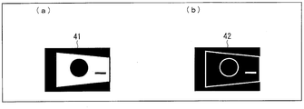
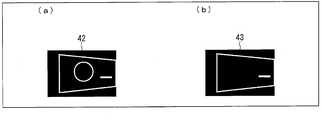
- the contour extraction unit 13 generates an edge image 42 by extracting the contour of the subject image from the captured image 41 received from the image input unit 12, as shown in FIGS. 4A and 4B.
- FIG. 4A is a diagram illustrating an example of a captured image
- FIG. 4B is a diagram illustrating an edge image generated from the captured image illustrated in FIG.
- an edge image is an image showing a sequence of points where the luminance value changes abruptly (discontinuously) in an image to be processed (that is, a captured image), and an image of a subject included in the image. It is an image which shows the curve or line segment which shows a boundary.
- the line segment extracting unit 14 extracts a contour line segment that is a line segment included in the contour of the image of the subject from the edge image generated by the contour extracting unit 13, and generates a line segment image indicating the contour line segment.
- the contour extraction unit 13 and the line segment extraction unit 14 generate a line segment image by extracting a contour line segment that is a line segment included in the contour of the image of the subject from the captured image obtained by capturing the subject. Functions as an image generation unit.
- the quadrangle candidate calculation unit 15 inserts at least one virtual line segment, which is a virtual line segment, into the line segment image generated by the line segment extraction unit 14, and is included in the inserted virtual line segment and line segment image.
- Four line segments are selected from the set of contour line segments, and a quadrilateral (quadron candidate) surrounded by four straight lines each including the four line segments is specified.
- the quadrilateral candidate calculating unit 15 inserts a virtual line segment along at least one side (in parallel with one side) of the four sides forming the outer edge of the line segment image or overlapping the one side.
- the number of virtual line segments to be inserted is at least one, but in order to reliably compensate for the missing portion of the image of the subject, a virtual line segment is inserted into each of the four sides forming the outer edge of the line segment image (that is, It is preferable to insert four virtual line segments).
- the quadrilateral candidate calculation unit 15 inserts one virtual line segment for each of the four sides forming the outer edge of the line segment image.
- the quadrilateral selection unit 16 displays the ranked quadrilateral candidates on the monitor 7 according to the ranking, and allows the user to select a quadrilateral (correction quadrilateral) to be used for correcting the captured image from the plurality of quadrilateral candidates, Information specifying the correction quadrilateral is received from the user.
- the image output unit 18 outputs the captured image (corrected image) corrected by the image correction unit 17 to the CPU 5. This corrected image is displayed on the monitor 7 and stored in the memory 3.
- the contour extraction unit 13 When the contour extraction unit 13 receives the captured image from the image input unit 12, the contour extraction unit 13 generates an edge image indicating the contour of the image of the subject from the received captured image (step S2). The contour extracting unit 13 outputs the generated edge image to the line segment extracting unit 14.
- the line segment extraction unit 14 extracts a contour line segment included in the contour of the image of the subject from the received edge image, and generates a line segment image indicating the contour line segment (step S3).
- the line segment extraction unit 14 outputs the generated line segment image to the quadrilateral candidate calculation unit 15.
- the quadrilateral candidate calculation unit 15 uses a plurality of quadrilaterals with reference to the lengths of the outline and virtual line segments that each quadrilateral candidate has.
- the shape candidates are ranked (step S6).
- the quadrilateral candidate calculation unit 15 outputs information indicating the ranked quadrilateral candidates to the quadrangle selection unit 16.
- the quadrangle candidate calculation unit 15 outputs correction quadrilateral specifying information for specifying the quadrilateral candidate to the image correction unit 17.
- the image output unit 18 outputs the captured image corrected by the image correction unit 17 to the CPU 5 (step S10).
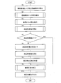
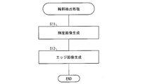
- FIG. 6 is a flowchart illustrating an example of a processing flow in the contour extraction unit 13.
- the contour extraction unit 13 generates a luminance image from the captured image received from the image input unit 12 (step S11).
- a luminance image is an image obtained by extracting only luminance value information from a captured image, and is a monochrome grayscale image that does not include color information.
- the R (red), G (green), and B (blue) values (luminance values) of the coordinates (x, y) of the captured image are r (x, y), g (x, y), and b (x), respectively. , Y), and the brightness value l (x, y) of the coordinates (x, y) of the brightness image is expressed by the following equation (1).
- c1, c2, and c3 are coefficients.
- c1, c2, and c3 are all 1/3, and averages of R, G, and B values are taken.
- the contour extraction unit 13 generates an edge image from the luminance image (step S12).
- a method for generating an edge image there is a method using an image processing filter such as Sobel or Prewitt.
- Sobel filter calculates an edge intensity value from a primary differential value that is a change amount of a luminance value in the x and y directions.
- the value e (x, y) of the coordinate (x, y) of the edge image is expressed by the following equations (2a), (2b), (2c) using the value l (x, y) of the coordinate (x, y) of the luminance image. ).
- ⁇ x ⁇ 1 ⁇ l (x ⁇ 1, y ⁇ 1) ⁇ 2 ⁇ l (x ⁇ 1, y) ⁇ 1 ⁇ l (x ⁇ 1, y + 1) + 1 ⁇ l (x + 1, y ⁇ 1) + 2 ⁇ l (X + 1, y) + 1 ⁇ l (x + 1, y + 1)
- ⁇ y ⁇ 1 ⁇ l (x ⁇ 1, y ⁇ 1) ⁇ 2 ⁇ l (x, y ⁇ 1) ⁇ 1 ⁇ l (x + 1, y ⁇ 1) + 1 ⁇ l (x ⁇ 1, y + 1) + 2 ⁇ l (X, y + 1) + 1 ⁇ l (x + 1, y + 1)
- e (x, y) ( ⁇ x ⁇ ⁇ x + ⁇ y ⁇ ⁇ y) 1/2
- e (x, y) is set to 0 when the edge value e (x, y) is smaller than a predetermined threshold in order to remove noise
- FIG. 7A is a diagram illustrating an example of an edge image generated by the contour extracting unit 13
- FIG. 7B is a diagram illustrating a line segment image generated from the edge image illustrated in FIG. FIG.
- Hough transform is used for line segment extraction.
- the Hough transform is to convert the coordinates (x, y) of the edge image into the coordinates ( ⁇ , ⁇ ) of the polar coordinate system, and the coordinates (x, y) are converted to ( ⁇ , ⁇ ) by the following equation (3). To do.
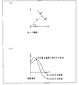
- FIG. 8 (a) and FIG. 8 (b) Expression (3) is shown in FIG. 8 (a) and FIG. 8 (b).
- 8A is a graph showing the positions of the points A and B in the xy coordinate system of the edge image
- FIG. 8B is a graph showing the (x, y) coordinates of the xy coordinate system in the polar coordinate system. It is a graph which shows the curve corresponding to the point A and the point B when it converts into coordinate ((rho), (theta)).
- the points A and B in the edge image each correspond to one curve in the polar coordinate system, and the straight line passing through the points A and B in the edge image corresponds to the intersection of two curves in the polar coordinate system.
- FIG. 10 is a flowchart showing an example of the processing flow in the line segment extraction unit 14.
- the line segment extraction unit 14 confirms whether there is an edge point that is not used for voting in the Hough transform (step S21).
- An edge point refers to a pixel whose edge value e is not 0 in the edge image.
- the line segment extraction unit 14 randomly selects an edge point from the edge point (step S22).
- the line segment extraction unit 14 votes the coordinates on the curve of the polar coordinate system for the selected edge point (step S23).
- the line segment extraction unit 14 confirms whether or not the vote number that is the maximum vote number in the previous step S23 is equal to or greater than a predetermined threshold (step S24).
- the line segment extraction unit 14 considers the maximum number of votes and calculates a corresponding straight line, and converts the calculated straight line into a plurality of line segments (step). S25). Specifically, the coordinates on the straight line are scanned in the edge image, and the portion where the edge points are connected is extracted as a line segment (contour line segment). However, extremely short line segments are not extracted as noise.
- the line segment extraction unit 14 removes the edge points on the extracted line segment by setting the value to 0 as being used for the straight line detection (step S26), and repeats the processing from step S21 onward.
- step S24 the line segment extracting unit 14 repeats the processes in and after step S21.
- step S21 the line segment extraction unit 14 creates a line segment image with the extracted line segment (step S27), and ends the process.
- the quadrilateral candidate calculation unit 15 calculates a plurality of quadrilaterals composed of line segments included in the line segment image as quadrilateral candidates used for correcting the captured image. However, in consideration of the case where the subject image does not fit in the captured image, a virtual line segment is inserted at the end of the line segment image.
- FIG. 11 is a diagram illustrating a line segment image 44 into which virtual line segments 45, 46, 47, and 48 are inserted. In the figure, four virtual line segments are inserted along the four sides forming the outer edge of the line segment image 44.
- the length of the virtual line segment may be substantially the same as the long side or the short side of the line segment image, or may be shorter than that, and is not particularly limited.
- the virtual line segment is preferably inserted in parallel to the outer edge side of the line segment image, but since the angle of the virtual line segment can be changed as in the embodiment described later, It is not always necessary to insert.
- the quadrilateral candidate calculation unit 15 ends the process because the quadrilateral cannot be formed.
- the quadrangle candidate calculation unit 15 selects four lines from the set of line segments including the virtual line segment (step S33). At this time, a combination not selected so far is selected. It is confirmed whether the four sides constituting the quadrilateral can be calculated for the selected four line segments (step S34).
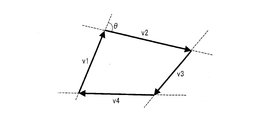
- FIG. 13 is a diagram illustrating straight lines that form four sides of a quadrilateral candidate.
- the number of intersections generated from the four straight lines is six at the maximum as shown in FIG.
- the four sides constituting the quadrilateral cannot be calculated. If the number of intersections is 4 or more, a quadrilateral having four sides of four lines obtained by selecting any four points from the intersections and dividing the straight line by the selected four points is expressed as follows. If all the conditions are met, the candidate is a quadrilateral. If there is a condition that does not satisfy even one, the four sides constituting the quadrilateral candidate cannot be calculated.
- FIG. 14 is a diagram for explaining a method for determining whether or not a quadrilateral is a convex shape.
- the sign of the outer product (v1 ⁇ v2) of the vectors v1 and v2 is the sign of sin ⁇ with respect to the angle ⁇ when v1 is rotated clockwise so as to overlap v2.
- FIGS. 15A to 15D are diagrams showing examples of captured images when the image of the subject does not fit in the captured image.
- a quadrilateral that shows a part of the contour of the subject image Can be calculated.
- FIG. 15 (d) shows a case where one of the four sides forming the contour of the subject image does not fit. The case where the two sides do not fit is shown.
- quadrilateral candidate calculation unit 15 stores the calculated four sides as a quadrilateral candidate (step S35).
- the quadrilateral candidate calculation unit 15 executes the processes in and after step S36.
- step S35 the quadrangle candidate calculation unit 15 confirms whether all line segment combinations have been selected (step S36).
- quadrilateral candidate calculation unit 15 orders the quadrilateral candidates in a reasonable order (step S37).
- the user of a digital camera seems to image the subject as large as possible.
- a line segment other than the line segment forming the contour of the image of the subject is a part of the sides of the quadrilateral candidate.
- the lengths of the line segments (contour line segment and virtual line segment) respectively corresponding to the four sides forming the quadrilateral candidate are used as evaluation values, and the quadrilateral candidates are ordered in descending order of the evaluation values. Since the virtual line segment is not an original line segment, the evaluation value may be decreased by multiplying the length included in the quadrilateral by a certain ratio of 1 or less.
- the quadrilateral candidate calculation unit 15 uses a value positively correlated with the length of the contour line segment and the virtual line segment as the evaluation value of the quadrilateral candidate, and the evaluation value for the unit length of the virtual line segment is the contour line. It is smaller than the evaluation value for the unit length of minutes.
- FIG. 16 is a diagram for explaining evaluation values of quadrilateral candidates.
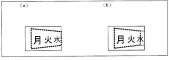
- FIGS. 17A and 17B are diagrams illustrating specific examples of quadrilateral candidates having different evaluation values.
- a quadrilateral indicated by a thick broken line represents a quadrilateral candidate.
- the sum of the lengths of line segments a, b, c, and d is an evaluation value.
- the length of the line segment part forming the side of the quadrilateral candidate is determined. Use the evaluation value.
- the quadrilateral candidate corresponding to the four sides forming the contour of the image of the subject has a long side, and the evaluation value increases because the line segment included in each side is long.
- the side of the quadrilateral candidate from a part of a character in the white board is used.
- the evaluation value is small because the line segment included in the side is short.
- the contour line segment that forms the contour of the image of the subject is extracted from the captured image.
- a line segment that does not form the contour of the subject image may be extracted as the contour line segment.
- the evaluation value is a value for lowering the priority of the quadrilateral candidate calculated based on the line segment that should not be extracted as the contour line segment.
- step S33 if the quadrilateral candidate calculation unit 15 has not selected all the line segment combinations (NO in step S36), the process from step S33 is repeated.
- a ranking unit that ranks the quadrilaterals may be provided.
- the ranking unit determines a plurality of identified quadrilaterals based on the lengths of the contour line segments and virtual line segments of each quadrilateral candidate for the plurality of quadrilateral candidates identified by the quadrilateral candidate calculating unit 15. Ranking.
- FIG. 18 is a diagram for explaining the significance of reducing the evaluation value of the virtual line segment.
- the quadrilateral to be detected in FIG. 18 is a quadrilateral surrounded by straight lines each including line segments s1, s2, s3, and s4.
- the line segment s2 is shorter than the side of the subject, but if the subject is slightly warped or the subject side itself is not a strict straight line due to lens distortion or the like, the extracted line segment is shorter than the actual side. Become.
- the virtual line segment can be used only when the subject image does not fit in the captured image. It is possible to increase the possibility that a quadrilateral including a character is ranked higher than a quadrilateral candidate.
- FIG. 19 is a diagram illustrating a display example of the captured image and the quadrangle candidate on the monitor 7.
- the quadrilateral selection unit 16 displays a captured image 81 and a quadrilateral candidate 82 on the monitor 7 as shown in FIG.
- the quadrilateral selection unit 16 uses the selected quadrilateral candidate for correcting the captured image.
- the correction quadrilateral is output to the image correction unit 17.
- the quadrilateral selection unit 16 first displays the quadrilateral candidate with the highest evaluation value.
- An example of the operation button 6 is shown in FIG. Each time the next candidate display button 61 is pressed, the next quadrilateral candidate is displayed in descending order of the evaluation value. Each time the previous candidate display button 62 is pressed, the next quadrilateral candidate is displayed in ascending order of evaluation values.
- the decision button 63 is pressed when correcting the image with the displayed quadrilateral candidate. That is, the button is pressed when the quadrilateral candidate displayed at that time is specified as a correction quadrilateral. By this operation, correction quadrilateral specifying information is input.
- the image correcting unit 17 calculates the aspect ratio of the subject according to the perspective transformation principle described below, and corrects the distorted quadrilateral on the captured image to a rectangle.
- FIG. 21 is a diagram illustrating the positional relationship of objects in perspective transformation.
- the positional relationship of objects in perspective transformation is shown in FIG. 21 in a three-dimensional vector space with the center of the lens as the origin O.
- the imaging surface 51 is perpendicular to the optical axis 52 of the optical system 1 and the distance from the lens center to the imaging surface 51 is the focal length d.
- the imaging surface 51 means an imaging surface in the image sensor 2.
- the positional relationship shown in FIG. 21 is generally used from the viewpoint of easy understanding. It is.
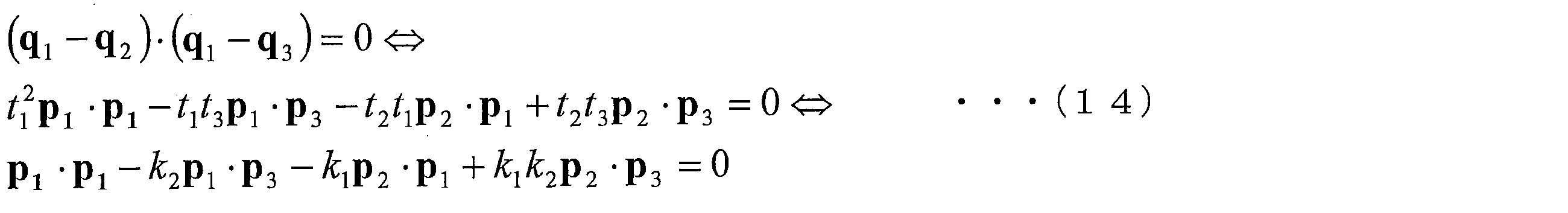
- the rectangular vertices of the subject 53 are defined as q 1 , q 2 , q 3 , and q 4, and the vertices of the distorted quadrilateral 51 a on the imaging surface 51 are defined as p 1 , p 2 , p 3 , and p 4 .
- p i (1 ⁇ i ⁇ 4) is defined by the following equation (4).
- ⁇ represents an inner product of vectors.
- Expression (6a) is a condition for forming a parallelogram
- Expression (6b) is a condition for allowing adjacent edges to be orthogonal.
- the following formula (7) is obtained from the formula (5) and the formula (6a).
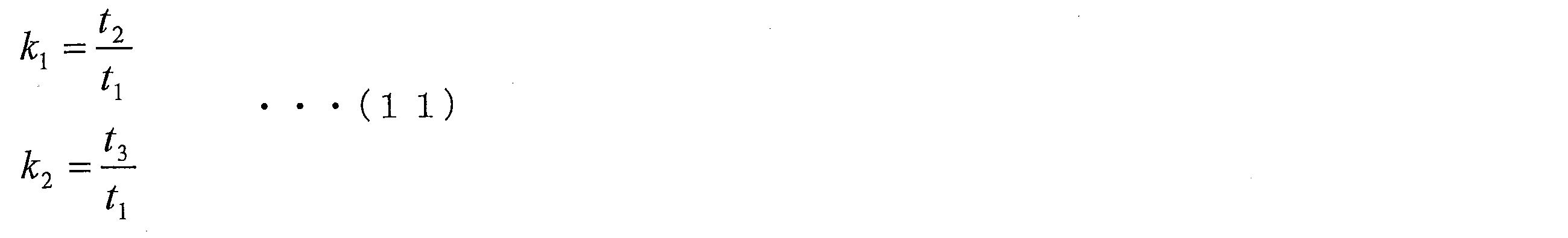
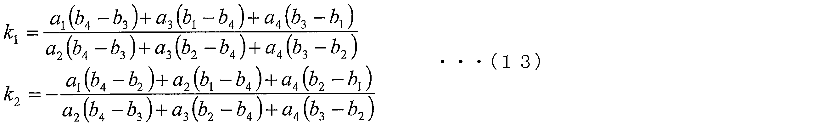
- Equation (12) is a simultaneous equation with respect to k 1 and k 2 , and the following equation (13) is obtained by solving this.
- the focal length may be given from the outside. That is, the focal length indicated by the focal length information received from the CPU 5 by the focal length input unit 11 may be used.
- the aspect ratio of the subject 53 is expressed by the following equation (16).
- a distance magnification t i (1 ⁇ i ⁇ 4) from the imaging surface 51 is determined for each vertex of the subject 53.
- FIGS. 22A and 22B The correspondence between the corrected pixel value and the distorted quadrilateral pixel before correction is shown in FIGS. 22A and 22B.
- FIG. 22A is a diagram illustrating an example of an image after correction
- FIG. 22B is a diagram illustrating an example of a quadrilateral included in the image before correction.
- the pixel values that divide the upper and lower sides of the rectangle 54 as the corrected image into m: (1-m) and the left and right sides into n: (1-n) are the four sides for correction included in the pre-correction image.
- the upper side of form 55 is internally divided into t 2 ⁇ m: t 1 ⁇ (1-m)
- the lower side is internally divided into t 4 ⁇ m: t 3 ⁇ (1-m)
- the left side is t 3 ⁇ n:
- a corrected image is calculated by using an interpolation method such as bilinear interpolation or bicubic interpolation.
- Bilinear interpolation is a method in which the weighted average pixel value of four pixels around the position calculated according to the internal ratio in the quadrilateral included in the pre-correction image is used as the pixel value of the post-correction image.
- Bicubic interpolation is a method for calculating pixel values of a corrected image using 16 neighboring pixels.
- FIG. 23 is a flowchart illustrating an example of a processing flow in the image correction unit 17.
- the image correction unit 17 checks whether or not the focal length can be calculated from the correction quadrilateral selected by the user in accordance with the perspective transformation principle (step S41).
- the image correcting unit 17 calculates the aspect ratio of the corrected image using the calculated focal length (step S42).
- the image correction unit 17 calculates the aspect ratio of the corrected image using the focal length input in the focal length input unit 11 (step S43).
- the image correction unit 17 creates a corrected image according to the perspective transformation principle using the aspect ratio of the corrected image and the distance magnification (step S44).
- contour extraction unit 13, the line segment extraction unit 14, the quadrilateral candidate calculation unit 15, and the quadrilateral selection unit 16 can reduce the processing cost by performing the above-described processing on the image obtained by reducing the captured image.
- the quadrangle candidate calculation unit 15 shapes the quadrangle candidate. Specifically, the quadrilateral candidate calculation unit 15 determines the position of the side including the virtual line segment so that the side including the virtual line segment included in the quadrilateral candidate identified by itself is parallel to the opposite side ( Change the (tilt). Therefore, in the present embodiment, the quadrangle candidate calculation unit 15 also has a function as a quadrilateral shaping unit. The image correction unit 17 corrects the perspective transformation distortion of the captured image based on the quadrangle candidate shaped by the quadrangle candidate calculation unit 15.
- FIG. 24 is a flowchart showing an example of a processing flow in the quadrangle candidate calculation unit 15 provided in the image processing apparatus 10 according to the present embodiment.
- the quadrangle candidate calculation unit 15 executes side correction processing (step S55) between step S34 and step S35 shown in FIG.
- Steps S51 to S54 shown in FIG. 24 are the same as steps S31 to S34, and steps S56 to S58 are the same as steps S35 to S37.
- the image correction unit 17 corrects the quadrangle candidate so that the side including the virtual line segment is parallel to the opposite side.
- a quadrilateral necessary for correction can be obtained even when the digital camera is rotated with respect to the subject.
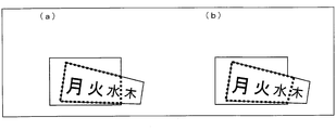
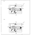
- FIG. 25A is a diagram showing a quadrilateral candidate before the side position is corrected
- FIG. 25B is a diagram showing the quadrilateral candidate after the side position is corrected.
- a quadrilateral indicated by a thick broken line is a quadrilateral candidate.
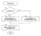
- FIG. 26 is a flowchart illustrating an example of the flow of edge correction processing.
- the quadrangle candidate calculation unit 15 checks whether or not the number of virtual line segments among the four line segments constituting the quadrangle is 1 (step S61).
- the quadrangle candidate calculation unit 15 adds both ends of the sides including the virtual line segments so that the sides including the virtual line segments are parallel to the opposite sides. The position of either one of the vertices is corrected (step S62).
- any position of the vertices at both ends of the side including the virtual line segment may be corrected, but it is preferable to correct the position of the vertex having the larger area of the generated quadrilateral. This is because the area of the subject image included in the corrected image becomes larger.
- the vertex after the position correction does not fit in the line segment image.
- a virtual image (virtual image) larger than the line segment image having the same coordinate system as that of the line segment image is formed, and four sides are used using the coordinates (pixel positions) in the virtual image.
- the positions of the four vertices of the shape candidate may be specified.
- the quadrilateral candidate calculation unit 15 calculates four sides of the quadrilateral including the corrected vertex (step S63).
- the process ends without doing anything.
- the number of virtual line segments is 0, 1 or 2 according to the selection conditions 4 and 5 of the quadrangle candidate in step S53 (FIG. 23) of the quadrangle candidate calculation process. If there are two virtual line segments, they are already arranged as parallel sides facing each other. If there are zero virtual line segments, it is not necessary to correct points because all are original line segments.
- a quadrilateral shaping unit may be provided separately from the quadrilateral candidate calculating unit 15, and the quadrilateral shaping unit may perform the above-described shaping for each of the quadrilateral candidates calculated by the quadrilateral candidate calculating unit 15.
- the image correction unit 17 corrects the perspective transformation distortion of the captured image based on the quadrilateral shaped by the quadrilateral shaping unit.
- Embodiment 3 The following will describe another embodiment of the present invention with reference to FIGS.
- symbol is attached
- insertion position information indicating the insertion position of the virtual line segment is received from the user of the digital camera 100, and the quadrilateral candidate calculation unit 15 inserts the virtual line segment at the insertion position indicated by the acquired insertion position information. To do.
- the operation button 6 or the monitor 7 Since the insertion position information is input via a soft key displayed on the operation button 6 or the monitor 7, the operation button 6 or the monitor 7 functions as an insertion position information acquisition unit that acquires the insertion position information.
- FIG. 27 is a flowchart illustrating an example of a processing flow in the quadrangle candidate calculation unit 15 included in the image processing apparatus 10 according to the present embodiment.
- a virtual line segment selection process by the user is executed before step S31 in FIG. 12 (step S71).
- Steps S72 to S78 shown in FIG. 27 are the same as steps S31 to S37.
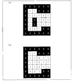
- FIG. 28A is a diagram showing an example of a monitor display screen when a virtual line segment is selected
- FIG. 28B is a diagram of the monitor 7 when the rightmost virtual line segment is selected. It is a figure which shows a display screen.
- the quadrilateral candidate calculation unit 15 displays the captured image 75 on the monitor 7 and cursors 71 to 74 indicating the insertion position of the virtual line segment. Are displayed in the vicinity of the upper, lower, left and right outer edge portions of the captured image 75, respectively.
- the user of the digital camera determines the insertion position of the virtual line segment using the operation button 6.
- the color of the cursor 72 corresponding to the rightmost virtual line segment changes as shown in FIG.
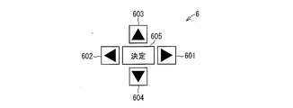
- FIG. 29 shows an example of the operation button 6 for inputting the insertion position of the virtual line segment.
- the right line segment selection button 601 When the right line segment selection button 601 is pressed, the rightmost virtual line segment is selected. When the right line segment selection button 601 is pressed again, the selection of the rightmost virtual line segment is canceled.
- a left line segment selection button 602, an upper line segment selection button 603, and an underline segment selection button 604 are arranged on the operation button 6. Selection is completed when the enter button 605 is pressed.
- the operation button 6 shown in FIG. 29 and the operation button 6 shown in FIG. 20 may share parts.
- the right line segment selection button 601 and the next candidate display button 61, the left line segment selection button 602 and the previous candidate display button 62, and the determination button 605 and the determination button 63 can share components.
- the operation button 6 is not necessarily realized as a physical button.
- a touch panel for detecting a touch position may be provided on the monitor 7 to detect the touch of a figure such as the cursors 71 to 74 displayed on the monitor 7 and perform the same processing as when the button is pressed.
- FIG. 30 is a block diagram showing a configuration of the image processing apparatus 20 according to the present embodiment. As shown in the figure, the image processing apparatus 20 is different from the image processing apparatus 10 in that it includes an insertion position determination unit 19 that determines a position where a virtual line segment is inserted.
- the insertion position determination unit 19 determines a missing portion of the subject image in the captured image on the outer edge of the captured image. Specifically, the insertion position determination unit 19 determines the insertion position of the virtual line segment by determining which of the four sides forming the outer edge of the captured image the subject image in the captured image intersects. . That is, the insertion position determination unit 19 determines the outer edge side of the captured image that is in contact with the subject image as the insertion position of the virtual line segment.
- the insertion position determination unit 19 sets the right end of the captured image as the insertion position of the virtual line segment. Judge as.
- the quadrilateral candidate calculation unit 15 inserts a virtual line segment so as to compensate for the missing portion determined by the insertion position determination unit 19. Specifically, the quadrilateral candidate calculation unit 15 inserts a virtual line segment so as to be close to or overlap the side determined by the insertion position determination unit 19.
- the subsequent processing of the quadrangle candidate calculation unit 15 is the same as the processing in the first embodiment described above.
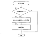
- FIG. 31 is a flowchart illustrating an example of a processing flow in the insertion position determination unit 19.
- FIGS. 32A and 32B are diagrams for explaining the insertion position determination process in the insertion position determination unit 19.
- the insertion position determination unit 19 binarizes the captured image (step S81).
- a binarization method for example, the method of Otsu can be used.
- Otsu's method is a method of taking a histogram for the luminance component of a captured image and selecting a threshold value that maximizes the inter-region variance when the histogram is classified into two regions according to a certain threshold value. Each pixel is classified into a white pixel and a black pixel by binarization.
- the insertion position determination unit 19 performs expansion processing and contraction processing on the binarized image a plurality of times for noise removal (step S82).
- the expansion process is a process of making a black pixel adjacent to a white pixel a white pixel, and a small black pixel region can be integrated into a white pixel region.
- the contraction process is a process of making a white pixel adjacent to a black pixel a black pixel, and a small white pixel region can be integrated into the black pixel region.
- a technique of performing the same number of contraction processes after a plurality of expansion processes is called closing, and applying the same number of expansion processes after a plurality of expansion processes is called opening. Noise can be removed by applying closing and opening in sequence.
- 32 (a) and 32 (b) are diagrams for explaining the insertion position determination process in the insertion position determination unit.
- the insertion position determination unit 19 performs a labeling process on the binarized image with noise removed (step S83). In this process, a number is assigned to the connected white pixel area or black pixel area.
- the insertion position determination unit 19 integrates the areas of the labeled areas that are smaller than a predetermined threshold into the surrounding areas (step S84).
- the insertion position determination unit 19 considers that the center of the image belongs to the image of the subject, and determines which side of the outer edges of the captured image is adjacent to the region including the center pixel (step S85). ). Then, the insertion position determination unit 19 outputs the position of the side of the captured image adjacent to the subject image to the quadrangle candidate calculation unit 15 as the virtual line segment insertion position.
- a region of the label having the largest number of pixels near the center of the captured image may be set as the subject region.
- the insertion position determination unit 19 displays information indicating that it is not necessary to insert a virtual line segment. What is necessary is just to output to the candidate calculation part 15. In this case, the quadrangle candidate calculation unit 15 calculates the quadrangle candidate without inserting the virtual line segment.
- FIG. 33 is a diagram showing a configuration of a computer 200 according to the present embodiment.
- the computer 200 includes an input device such as a keyboard 201 and a mouse 202, a CPU (Central Processing Unit) 204, a memory 206 including a ROM (Read Only Memory) and a RAM (Random Access Memory), and a fixed disk (storage unit) 207. And an output interface 203.
- the computer 200 outputs the display image to the monitor 205 through the output interface 203.
- the computer 200 includes an optical disc drive 209 that can read data from an optical disc such as a CD-ROM (Compact Disk Read-Only Memory) 212, an FD drive 208 that can read data from a flexible disk (FD: Flexible Disk) 211, It further includes a communication module 210 that can exchange data with an external device.
- an optical disc drive 209 that can read data from an optical disc such as a CD-ROM (Compact Disk Read-Only Memory) 212
- an FD drive 208 that can read data from a flexible disk (FD: Flexible Disk) 211
- FD Flexible Disk
- An image processing program for causing the CPU 204 to execute each of the processes described above in the image processing apparatus 10 or the image processing apparatus 20 is stored and distributed in a recording medium such as the CD-ROM 212 or the flexible disk 211, and the optical disk drive 209 or the FD. It is read by the drive 208 and installed on the fixed disk 207.
- the storage unit for storing the image processing program in the computer 200 is not limited to a fixed disk, and may be a flash memory (semiconductor memory) such as an SSD (Solid State Drive).
- flash memory semiconductor memory
- SSD Solid State Drive
- the computer 200 when the computer 200 is connected to the network via the communication module 210, it receives the image processing program transmitted from the server on the network and installs it on the fixed disk 207. May be.
- the image processing program When receiving an image processing program via a network, the image processing program may be executed after being loaded on the RAM without being installed on the fixed disk 207.
- the recording medium for storing the image processing program is not limited to the CD-ROM 212 and the flexible disk 211, and may be, for example, a DVD-ROM (Digital Versatile Disk) or a memory card.
- a drive device capable of reading such a recording medium is provided.
- the CPU 204 reads a captured image of the digital camera from the fixed disk 207, the CD-ROM 212, or the flexible disk 211, stores it in the memory 206, and displays it on the monitor 205. Then, the CPU 204 creates a corrected image without distortion from the captured image, stores it in the memory 206, and displays it on the monitor 205 via the output interface 203.
- the focal length input unit 11 stores in the memory 206 the focal length when the captured image to be corrected is captured.
- the focal length may be read from Exif included in the captured image data, or the focal length calculated when the captured image was corrected previously is stored in the fixed disk 207 in association with the captured image, The focal length may be read into the memory 206.
- the quadrilateral selection unit 16 displays the captured image and quadrilateral candidates on the monitor 205 via the output interface 203, and the user of the computer 200 uses the keyboard 201 and the mouse 202 instead of the operation buttons 6 to select the quadrilateral. Select a quadrilateral from the candidates. For example, the design of the operation button shown in FIG. 20 is displayed on the monitor 205, and processing corresponding to the case where the operation button is pressed when the mouse 202 is clicked is executed.
- the image output unit 18 stores the corrected image in the memory 206 and displays it on the monitor 205.
- part of the processing performed by the computer 200 shown in FIG. 33 may be performed by another computer connected via the communication module.
- the computer 200 transmits a captured image, receives quadrilateral candidates calculated by another computer, and displays them on the monitor 205.
- the computer 200 transmits the quadrilateral selected by the user, receives the corrected image created by another computer, and displays it on the monitor 205.
- the computer 200 transmits a captured image, receives a corrected image corrected by another computer using a quadrilateral candidate having the highest evaluation value, and displays it on the monitor 205.
- the quadrilateral specifying unit displays the virtual line segment so as to be along or overlap with at least one of the four sides forming the outer edge of the line segment image. It is preferable to insert.
- the virtual line segment may have a predetermined length, and the length is not particularly limited.
- the image processing apparatus further includes an insertion position information acquisition unit that receives insertion position information indicating an insertion position of the virtual line segment from a user, and the quadrilateral identification unit is acquired by the insertion position information acquisition unit. It is preferable to insert the virtual line segment at the insertion position indicated by the insertion position information.
- the insertion position information acquisition unit receives insertion position information indicating the insertion position of the virtual line segment from the user, and the quadrilateral specifying unit inserts the virtual line segment at the insertion position indicated by the insertion position information. To do.
- the image processing apparatus may further include a determination unit that determines a missing portion of the image of the subject in the captured image on the outer edge of the captured image, and the quadrilateral specifying unit is a missing portion determined by the determination unit. It is preferable to insert the imaginary line segment so as to supplement the portion.
- the determination unit determines the missing portion on the outer edge of the captured image, and the virtual line segment is inserted so as to compensate for the missing portion.
- the image processing apparatus further includes a determination unit that determines which of the four sides forming the outer edge of the captured image the image of the subject in the captured image is in contact with. It is preferable to insert the virtual line segment along the side determined by the determination unit or so as to overlap the side.
- the determination unit determines which of the four sides (outer edge sides) forming the outer edge of the captured image is in contact with the subject image in the captured image.
- this processing it is possible to determine in which outer edge of the captured image the missing image of the subject is generated. This is because there is a high possibility that the image of the subject is missing in the portion of the image of the subject in contact with the outer edge.
- the image processing apparatus changes the position of the side including the virtual line segment so that the side including the virtual line segment included in the quadrilateral specified by the quadrilateral specifying unit is parallel to the opposite side. It is preferable that the image correction unit further corrects the perspective transformation distortion of the captured image based on the quadrilateral shaped by the quadrangle shaping unit.
- the quadrilateral shaping unit is opposed to the sides including the virtual line segment (in other words, the side formed by the virtual line segment) included in the quadrilateral identified by the quadrilateral identifying unit.
- the position of the side including the virtual line segment is changed so as to be parallel to the side.
- the image correction unit corrects the perspective transformation distortion of the captured image based on the quadrilateral shaped by the quadrilateral shaping unit.
- the image processing device includes a plurality of specified quadrilaterals based on the lengths of the contour line segments and virtual line segments included in each quadrilateral. It is preferable to further include a ranking unit that ranks the shapes.
- the quadrangle is ranked by the ranking unit. This ranking is performed on the basis of the lengths of contour lines and virtual lines included in each quadrilateral. For example, the quadrilaterals are ranked in descending order of the total length of the line segments included in each quadrilateral.
- the quadrilateral specifying unit uses a value positively correlated with the contour line segment and the length of the virtual line segment as the evaluation value of the quadrilateral, and the evaluation value for the unit length of the virtual line segment is: It is preferably smaller than the evaluation value for the unit length of the contour line segment.
- the evaluation value of the quadrilateral used by the quadrilateral specifying unit is positively correlated with the lengths of the contour line segment and the virtual line segment. That is, as the length of the line segment increases, the evaluation value of the quadrilateral including the line segment increases.
- the evaluation value for the unit length of the virtual line segment is set smaller than the evaluation value for the unit length of the contour line segment.
- the length of the contour line segment extracted from the contour of the subject image can be shortened by partially distorting the subject image or by fragmenting the contour line segment due to the low contrast of the subject image.
- the virtual line segment has a predetermined length, and when the predetermined length is long, the length of the virtual line segment is statistically longer than the length of the contour line segment. It is possible.
- the evaluation value for the unit length of the virtual line segment By setting the evaluation value for the unit length of the virtual line segment to be smaller than the evaluation value for the unit length of the contour line segment, an unnecessary virtual line segment is inserted, and a quadrilateral including the virtual line segment is specified. The evaluation value of the quadrilateral can be reduced.
- an image processing program for causing a computer to execute each step in the image processing method, and a computer-readable recording medium on which the image processing program is recorded.
- each block of the digital camera 100 described above, particularly each block of the image processing apparatuses 10 and 20 may be configured by hardware logic, or may be realized by software using a CPU as follows.
- the image processing apparatuses 10 and 20 include a CPU (central processing unit) that executes instructions of a control program that realizes each function, a ROM (read only memory) that stores the program, and a RAM (random access that expands the program). memory), a storage device (recording medium) such as a memory for storing the program and various data.
- a CPU central processing unit
- ROM read only memory
- RAM random access that expands the program
- memory a storage device (recording medium) such as a memory for storing the program and various data.
- An object of the present invention is to read a program code (execution format program, intermediate code program, source program) of a control program (image processing program) of the image processing apparatus 10/20, which is software that realizes the functions described above, by a computer
- This can also be achieved by supplying a recording medium recorded as possible to the image processing apparatuses 10 and 20 and reading and executing the program code recorded on the recording medium by the computer (or CPU or MPU).
- Examples of the recording medium include tapes such as magnetic tapes and cassette tapes, magnetic disks such as floppy (registered trademark) disks / hard disks, and disks including optical disks such as CD-ROM / MO / MD / DVD / CD-R.
- Card system such as IC card, IC card (including memory card) / optical card, or semiconductor memory system such as mask ROM / EPROM / EEPROM / flash ROM.
- the image processing apparatuses 10 and 20 may be configured to be connectable to a communication network, and the program code may be supplied via the communication network.
- the communication network is not particularly limited.
- the Internet intranet, extranet, LAN, ISDN, VAN, CATV communication network, virtual private network, telephone line network, mobile communication network, satellite communication. A net or the like is available.
- the transmission medium constituting the communication network is not particularly limited.
- infrared rays such as IrDA and remote control, Bluetooth ( (Registered trademark), 802.11 wireless, HDR (high data rate), mobile phone network, satellite line, terrestrial digital network, and the like can also be used.
- the present invention can also be realized in the form of a computer data signal embedded in a carrier wave in which the program code is embodied by electronic transmission.
- the present invention can also be expressed as follows.
- the image processing apparatus of the present invention includes an image input unit, a line segment extraction unit that extracts a line segment from the image input by the image input unit, and a virtual line segment (virtual line segment) in the image.
- a virtual line segment insertion unit for inserting a quadrilateral candidate calculation unit for calculating a quadrilateral candidate from the line segment (extracted line segment) obtained by the line segment extraction unit and the virtual line segment, and the quadrilateral candidate calculation unit
- an image correction unit that corrects the perspective transformation distortion of the image based on the quadrangle calculated in (1).
- the virtual line segment insertion unit inserts the virtual line segment into one or a plurality of positions from the upper, lower, left and right ends of the image.
- the quadrilateral candidate calculating unit corrects the position of the side including the virtual line segment in the quadrilateral candidate so as to be parallel to the opposite side.
- the quadrilateral candidate calculation unit orders the quadrilateral candidates based on an evaluation value based on the lengths of the extracted line segments and the virtual line segments included in the quadrilateral candidates.
- the evaluation value is preferably such that the evaluation value based on the length of the virtual line segment is smaller than the evaluation value based on the length of the extracted line segment.
- the present invention can be used as an image processing apparatus that corrects distortion of an image of a subject included in a captured image.
- Image Processing Device 13 Outline Extraction Unit (Line Segment Image Generation Unit) 14 Line segment extraction unit (line segment image generation unit) 15 Quadrilateral candidate calculation unit (quadron identification unit, quadrilateral shaping unit, ranking unit) 17 Image correction unit 19 Insertion position determination unit (determination unit) 20 Image Processing Device 41 Captured Image 44 Line Segment Image 45/46/47/48/49 Virtual Line Segment 53 Subject 55 Quadrilateral 100 Digital Camera (Image Processing Device) 110 White board (subject) 111 captured image 113 corrected image 200 computer (image processing apparatus)
Landscapes
- Engineering & Computer Science (AREA)
- Multimedia (AREA)
- Signal Processing (AREA)
- Physics & Mathematics (AREA)
- General Physics & Mathematics (AREA)
- Theoretical Computer Science (AREA)
- Computer Vision & Pattern Recognition (AREA)
- Image Processing (AREA)
- Studio Devices (AREA)
- Editing Of Facsimile Originals (AREA)
- Image Analysis (AREA)
Abstract
Description
本発明の実施の一形態について図1~図23に基づいて説明すれば、以下のとおりである。ここでは、本発明の画像処理装置をデジタルカメラで実施する形態を説明する。ただし、本発明の画像処理装置は、デジタルカメラに限定されず、内蔵する撮像装置または外部の装置から撮像画像データを取得し、その撮像画像データを処理する装置(例えば、スキャナー、プリンター、携帯電話)であれば、どのような装置であってもよい。
図2は、本実施の形態のデジタルカメラ100の機能を説明するための図である。デジタルカメラ100で白板110を斜め方向から撮像すると、撮像画像111における白板の像112は歪む。また、スケジュールボードなどの被写体が大きい場合は被写体の像一部が撮像画像に収まらない場合がある。歪んだ撮像画像をデジタルカメラ100により補正すると補正後画像113のような歪みのない白板の像114を含む画像が得られる。特に、被写体の像一部が撮像画像に収まらない場合においても歪みのない画像が得られる。
図3は、デジタルカメラ100の構成を示す図である。同図に示すように、デジタルカメラ100は、光学系1、イメージセンサ2、メモリ3、カードリーダライタ4、CPU(中央処理装置)5、操作ボタン6、モニタ(表示部)7および画像処理装置10を備えている。
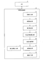
図1は、画像処理装置10の構成を示すブロック図である。同図に示すように、画像処理装置10は、焦点距離入力部11、画像入力部12、輪郭抽出部(線分画像生成部)13、線分抽出部(線分画像生成部)14、四辺形候補算出部(四辺形特定部、順位付け部)15、四辺形選択部16、画像補正部17および画像出力部18を備えている。
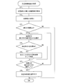
次に画像処理装置10における処理の大まかな流れについて説明する。各処理の詳細については後述する。なお、ここでは、仮想線分を4本挿入する場合の処理について説明する。
図6は、輪郭抽出部13における処理の流れの一例を示すフローチャートである。最初に、輪郭抽出部13は、画像入力部12から受け取った撮像画像から輝度画像を生成する(ステップS11)。輝度画像とは、撮像画像から輝度値の情報のみを抽出した画像であり、色情報を含まないモノクロ濃淡画像である。例えば、撮像画像の座標(x,y)のR(赤)、G(緑)、B(青)値(輝度値)がそれぞれr(x,y)、g(x,y)、b(x,y)であるとし、輝度画像の輝度をL値で表わすと、輝度画像の座標(x,y)の輝度値l(x,y)は下記式(1)によって表わされる。
式(1)において、c1、c2、c3は係数である。輝度画像を得るためには、例えばc1、c2、c3をすべて1/3としてR、G、B値の平均を取る。別の場合には、c1=0.299、c2=0.587、c3=0.114としてYUVフォーマットのY値を算出してもよい。
Δx=-1×l(x-1,y-1)-2×l(x-1,y)-1×l(x-1,y+1)+1×l(x+1,y-1)+2×l(x+1,y)+1×l(x+1,y+1) ・・・(2a)
Δy=-1×l(x-1,y-1)-2×l(x,y-1)-1×l(x+1,y-1)+1×l(x-1,y+1)+2×l(x,y+1)+1×l(x+1,y+1) ・・・(2b)
e(x,y)=(Δx×Δx+Δy×Δy)1/2 ・・・(2c)
ただし、ノイズを除去するためエッジの値e(x,y)が所定の閾値よりも小さい場合は、e(x,y)を0にする。
線分抽出部14は、四辺形を抽出するための前処理として、図7の(a)および図7の(b)に示すようにエッジ画像42から線分を抽出し、線分画像43を生成する。図7の(a)は、輪郭抽出部13が生成したエッジ画像の一例を示す図であり、図7の(b)は、図7の(a)に示すエッジ画像から生成した線分画像を示す図である。線分抽出にはハフ変換を用いる。ハフ変換とはエッジ画像の座標(x,y)を極座標系の座標(ρ,θ)に変換することであり、下記式(3)によって座標(x,y)を(ρ,θ)に変換する。
式(3)を図で示すと図8の(a)および図8の(b)のようになる。図8の(a)は、エッジ画像のxy座標系における点Aおよび点Bの位置を示すグラフであり、図8の(b)は、xy座標系の(x,y)座標を極座標系の座標(ρ,θ)に変換したときの点Aおよび点Bに対応する曲線を示すグラフである。エッジ画像中の点A、点Bは、極座標系ではそれぞれ1本の曲線に対応し、エッジ画像中の点Aおよび点Bを通る直線は極座標系では2つの曲線の交点に対応する。ここで、ρはエッジ画像中の原点から直線への法線ベクトルの長さ、θは法線ベクトルとx軸が成す角度に相当する。ただし、θは0°≦θ<180°であり、180°以上の範囲ではρが負の値で表現される。
四辺形候補算出部15は、線分画像に含まれる線分から構成される複数の四辺形を、撮像画像の補正に用いる四辺形の候補として算出する。ただし、被写体の像が撮像画像に収まっていない場合を考慮して、線分画像の端に仮想線分を挿入する。図11は、仮想線分45・46・47・48を挿入した線分画像44を示す図である。同図では、線分画像44の外縁を形成する四辺に沿って4本の仮想線分が挿入されている。
条件1:上記4辺で構成される四辺形が凸型である。
条件2:上記4辺で構成される四辺形の隣り合う頂点間に直線が存在する。
条件3:上記4辺で構成される四辺形の向かい合う頂点間に直線が存在しない。
条件4:上記4辺のうち仮想線分を含む辺は2本以下である。
条件5:上記4辺のうち仮想線分を含む辺が2本の場合は、仮想線分は4辺で構成される四辺形の向かい合う2辺に対応する。
ここで、四辺形に含まれる仮想線分の長さに対して1以下の一定の割合を掛けることにより評価値を小さくすることの意義について説明する。図18は、仮想線分の評価値を小さくすることの意義を説明するための図である。
図19は、撮像画像および四辺形候補のモニタ7における表示例を示す図である。四辺形選択部16は、図19に示すように、モニタ7に撮像画像81と四辺形候補82とを表示する。デジタルカメラ100の使用者が操作ボタン6を用いて複数の四辺形候補の中から1つの四辺形候補を選択すると、四辺形選択部16は、選択された四辺形候補を撮像画像の補正に用いる補正用四辺形として画像補正部17へ出力する。
画像補正部17は、以下に説明する透視変換の原理にしたがって、被写体の縦横比を算出し、撮像画像上の歪んだ四辺形を長方形に補正する。
まず被写体の縦横比の算出方法を示す。図21は、透視変換における物体の位置関係を示す図である。図21を用いて透視変換における物体の位置関係を、レンズの中心を原点Oとして3次元のベクトル空間で示す。撮像面51は光学系1の光軸52に垂直であり、レンズ中心から撮像面51までの距離が焦点距離dとなる。撮像面51とは、デジタルカメラ100では、イメージセンサ2における撮像面を意味する。物理的な位置関係では撮像面51はレンズの中心に対して被写体53とは反対の位置に存在するが、透視変換では理解の容易さの観点から図21に示す位置関係を用いることが一般的である。

被写体53は長方形であるため、下記式(6a)および(6b)が成り立つ。
(q1-q2)・(q1-q3)=0 ・・・(6b)
式(6b)において「・」はベクトルの内積を表す。式(6a)は平行四辺形となるための条件であり、式(6b)は隣り合う辺が直交するための条件である。
式(5)と式(6a)とにより、下記式(7)が得られる。


次に歪んだ四辺形を長方形に補正する方法を示す。
t2=k1 ・・・(17)
t3=k2
t4=k1+k2-1
補正後の画像として、式(16)で求めた縦横比に従う適当な大きさの長方形を用意する。このときの補正後の画素の値と補正前の歪んだ四辺形の画素との対応関係を図22の(a)および図22の(b)に示す。図22の(a)は、補正後の画像の一例を示す図であり、図22の(b)は、補正前の画像に含まれる四辺形の一例を示す図である。
図23は画像補正部17における処理の流れの一例を示すフローチャートである。画像補正部17は、最初に使用者によって選択された補正用四辺形から透視変換の原理に従って焦点距離を算出できるかどうかを確認する(ステップS41)。
本発明の他の実施形態について図24~図26に基づいて説明すれば、以下のとおりである。なお、実施の形態1と同様の部材に関しては、同じ符号を付し、その説明を省略する。ここでは、四辺形候補算出部15において、四辺形候補の整形を行う実施形態について説明する。具体的には、四辺形候補算出部15は、自身が特定した四辺形候補が有する、仮想線分を含む辺が、対向する辺と平行になるように当該仮想線分を含む辺の位置(傾き)を変更する。それゆえ、本実施の形態では、四辺形候補算出部15は、四辺形整形部としての機能も有している。画像補正部17は、四辺形候補算出部15が整形した四辺形候補に基づいて撮像画像の透視変換歪みを補正する。
図26は、辺補正処理の流れの一例を示すフローチャートである。辺補正処理では最初に、四辺形候補算出部15は、四辺形を構成する4本の線分のうち仮想線分の個数が1かどうかを確認する(ステップS61)。
本発明の他の実施形態について図27~図29に基づいて説明すれば、以下のとおりである。なお、実施の形態1・2と同様の部材に関しては、同じ符号を付し、その説明を省略する。
本発明の他の実施形態について図30~図32に基づいて説明すれば、以下のとおりである。なお、実施の形態1~3と同様の部材に関しては、同じ符号を付し、その説明を省略する。
図30は、本実施の形態に係る画像処理装置20の構成を示すブロック図である。同図に示すように画像処理装置20は、仮想線分を挿入する位置を判定する挿入位置判定部19を備えている点で画像処理装置10と異なっている。
次に、挿入位置判定部19における挿入位置判定処理の詳細について説明する。図31は挿入位置判定部19における処理の流れの一例を示すフローチャートである。図32の(a)および図32の(b)は、挿入位置判定部19における挿入位置判定処理を説明するための図である。
本発明の他の実施形態について図33に基づいて説明すれば、以下のとおりである。
図33は、本実施の形態にかかるコンピュータ200の構成を示す図である。
本実施の形態にかかるコンピュータ200の処理の流れは、実施の形態1の画像処理装置10における処理の流れ(図5参照)とほぼ同様である。以下、各処理の詳細において、実施の形態1と異なる部分について説明する。
本発明は上述した各実施形態に限定されるものではなく、請求項に示した範囲で種々の変更が可能であり、異なる実施形態にそれぞれ開示された技術的手段を適宜組み合わせて得られる実施形態についても本発明の技術的範囲に含まれる。
13 輪郭抽出部(線分画像生成部)
14 線分抽出部(線分画像生成部)
15 四辺形候補算出部(四辺形特定部、四辺形整形部、順位付け部)
17 画像補正部
19 挿入位置判定部(判定部)
20 画像処理装置
41 撮像画像
44 線分画像
45・46・47・48・49 仮想線分
53 被写体
55 四辺形
100 デジタルカメラ(画像処理装置)
110 白板(被写体)
111 撮像画像
113 補正後画像
200 コンピュータ(画像処理装置)
Claims (12)
- 被写体を撮像した撮像画像から、上記被写体の像の輪郭に含まれる線分である輪郭線分を抽出した線分画像を生成する線分画像生成部と、
上記線分画像生成部が生成した線分画像に仮想的な線分である仮想線分を少なくとも1本挿入し、挿入した仮想線分および上記輪郭線分の集合から4本の線分を選択し、その4本の線分をそれぞれ含む4本の直線によって囲まれる四辺形を特定する四辺形特定部と、
上記四辺形特定部が特定した四辺形に基づいて上記撮像画像の透視変換歪みを補正する画像補正部とを備えることを特徴とする画像処理装置。 - 上記四辺形特定部は、上記線分画像の外縁を形成する四辺のうちの少なくとも一辺に沿ってまたは当該一辺に重なるように上記仮想線分を挿入することを特徴とする請求項1に記載の画像処理装置。
- 上記四辺形特定部は、上記線分画像の外縁を形成する四辺のそれぞれに対して上記仮想線分を挿入することを特徴とする請求項1または2に記載の画像処理装置。
- 上記仮想線分の挿入位置を示す挿入位置情報を使用者から受け付ける挿入位置情報取得部をさらに備え、
上記四辺形特定部は、上記挿入位置情報取得部が取得した挿入位置情報が示す挿入位置に上記仮想線分を挿入することを特徴とする請求項1または2に記載の画像処理装置。 - 上記撮像画像における上記被写体の像の、当該撮像画像の外縁辺における欠落部分を判定する判定部をさらに備え、
上記四辺形特定部は、上記判定部が判定した欠落部分を補うように、上記仮想線分を挿入することを特徴とする請求項1に記載の画像処理装置。 - 上記撮像画像における上記被写体の像が、当該撮像画像の外縁を形成する四辺のいずれと接しているかを判定する判定部をさらに備え、
上記四辺形特定部は、上記判定部が判定した辺に沿って、または当該辺に重なるように上記仮想線分を挿入することを特徴とする請求項1に記載の画像処理装置。 - 上記四辺形特定部が特定した四辺形が有する、上記仮想線分を含む辺が、対向する辺と平行になるように当該仮想線分を含む辺の位置を変更する四辺形整形部をさらに備え、
上記画像補正部は、上記四辺形整形部が整形した四辺形に基づいて上記撮像画像の透視変換歪みを補正することを特徴とする請求項1~6のいずれか1項に記載の画像処理装置。 - 上記四辺形特定部が上記四辺形を複数特定した場合に、各四辺形に含まれる輪郭線分および仮想線分の長さを基準として、特定された複数の四辺形を順位付ける順位付け部をさらに備えることを特徴とする請求項1~6のいずれか1項に記載の画像処理装置。
- 上記四辺形特定部は、上記輪郭線分および上記仮想線分の長さと正の相関のある値を上記四辺形の評価値として用い、
上記仮想線分の単位長さに対する評価値は、上記輪郭線分の上記単位長さに対する評価値よりも小さいことを特徴とする請求項8に記載の画像処理装置。 - 画像処理装置における画像処理方法であって、
被写体を撮像した撮像画像から、上記被写体の像の輪郭に含まれる線分である輪郭線分を抽出した線分画像を生成する線分画像生成工程と、
上記線分画像生成工程において生成した線分画像に仮想的な線分である仮想線分を少なくとも1本挿入し、挿入した仮想線分および上記輪郭線分の集合から4本の線分を選択し、その4本の線分をそれぞれ含む4本の直線によって囲まれる四辺形を特定する四辺形特定工程と、
上記四辺形特定工程において特定した四辺形に基づいて上記撮像画像の透視変換歪みを補正する画像補正工程とを含むことを特徴とする画像処理方法。 - 請求項10に記載の上記各工程をコンピュータに実行させるための画像処理プログラム。
- 請求項11に記載の画像処理プログラムを記録したコンピュータ読み取り可能な記録媒体。
Priority Applications (3)
| Application Number | Priority Date | Filing Date | Title |
|---|---|---|---|
| CN2010800487099A CN102648622A (zh) | 2009-10-28 | 2010-08-04 | 图像处理装置、图像处理方法、图像处理程序、记录有图像处理程序的记录介质 |
| EP10826411.0A EP2495949A4 (en) | 2009-10-28 | 2010-08-04 | PICTURE PROCESSING DEVICE, PICTURE PROCESSING METHOD, PICTURE PROCESSING PROGRAM, AND RECORDING MEDIUM WITH PICTURE PROCESSING MAIL RECORDED THEREFOR |
| US13/504,424 US8731321B2 (en) | 2009-10-28 | 2010-08-04 | Image processing device, image processing method, image processing program, and recording medium with recorded image processing program |
Applications Claiming Priority (2)
| Application Number | Priority Date | Filing Date | Title |
|---|---|---|---|
| JP2009-247788 | 2009-10-28 | ||
| JP2009247788A JP4630936B1 (ja) | 2009-10-28 | 2009-10-28 | 画像処理装置、画像処理方法、画像処理プログラム、画像処理プログラムを記録した記録媒体 |
Publications (1)
| Publication Number | Publication Date |
|---|---|
| WO2011052276A1 true WO2011052276A1 (ja) | 2011-05-05 |
Family
ID=43638558
Family Applications (1)
| Application Number | Title | Priority Date | Filing Date |
|---|---|---|---|
| PCT/JP2010/063220 Ceased WO2011052276A1 (ja) | 2009-10-28 | 2010-08-04 | 画像処理装置、画像処理方法、画像処理プログラム、画像処理プログラムを記録した記録媒体 |
Country Status (5)
| Country | Link |
|---|---|
| US (1) | US8731321B2 (ja) |
| EP (1) | EP2495949A4 (ja) |
| JP (1) | JP4630936B1 (ja) |
| CN (1) | CN102648622A (ja) |
| WO (1) | WO2011052276A1 (ja) |
Families Citing this family (55)
| Publication number | Priority date | Publication date | Assignee | Title |
|---|---|---|---|---|
| US20050097046A1 (en) | 2003-10-30 | 2005-05-05 | Singfield Joy S. | Wireless electronic check deposit scanning and cashing machine with web-based online account cash management computer application system |
| US8708227B1 (en) | 2006-10-31 | 2014-04-29 | United Services Automobile Association (Usaa) | Systems and methods for remote deposit of checks |
| US7873200B1 (en) | 2006-10-31 | 2011-01-18 | United Services Automobile Association (Usaa) | Systems and methods for remote deposit of checks |
| US10380559B1 (en) | 2007-03-15 | 2019-08-13 | United Services Automobile Association (Usaa) | Systems and methods for check representment prevention |
| US9058512B1 (en) | 2007-09-28 | 2015-06-16 | United Services Automobile Association (Usaa) | Systems and methods for digital signature detection |
| US9892454B1 (en) | 2007-10-23 | 2018-02-13 | United Services Automobile Association (Usaa) | Systems and methods for obtaining an image of a check to be deposited |
| US9159101B1 (en) | 2007-10-23 | 2015-10-13 | United Services Automobile Association (Usaa) | Image processing |
| US10380562B1 (en) | 2008-02-07 | 2019-08-13 | United Services Automobile Association (Usaa) | Systems and methods for mobile deposit of negotiable instruments |
| US10504185B1 (en) | 2008-09-08 | 2019-12-10 | United Services Automobile Association (Usaa) | Systems and methods for live video financial deposit |
| JP2012504832A (ja) | 2008-10-02 | 2012-02-23 | ボールズ、マーク | デバイスに対する二次市場およびベンディングシステム |
| US8452689B1 (en) | 2009-02-18 | 2013-05-28 | United Services Automobile Association (Usaa) | Systems and methods of check detection |
| US10956728B1 (en) | 2009-03-04 | 2021-03-23 | United Services Automobile Association (Usaa) | Systems and methods of check processing with background removal |
| US9779392B1 (en) | 2009-08-19 | 2017-10-03 | United Services Automobile Association (Usaa) | Apparatuses, methods and systems for a publishing and subscribing platform of depositing negotiable instruments |
| US8977571B1 (en) | 2009-08-21 | 2015-03-10 | United Services Automobile Association (Usaa) | Systems and methods for image monitoring of check during mobile deposit |
| US8699779B1 (en) | 2009-08-28 | 2014-04-15 | United Services Automobile Association (Usaa) | Systems and methods for alignment of check during mobile deposit |
| US9129340B1 (en) | 2010-06-08 | 2015-09-08 | United Services Automobile Association (Usaa) | Apparatuses, methods and systems for remote deposit capture with enhanced image detection |
| JP5708051B2 (ja) * | 2011-03-07 | 2015-04-30 | 株式会社リコー | 映像処理装置、映像処理システム、テレビ会議システム、遠方監視システム、映像処理方法、及び撮像装置 |
| JP5742399B2 (ja) * | 2011-04-06 | 2015-07-01 | 富士ゼロックス株式会社 | 画像処理装置及びプログラム |
| JP5488548B2 (ja) | 2011-08-04 | 2014-05-14 | カシオ計算機株式会社 | 画像処理装置、画像処理方法及びプログラム |
| JP6049000B2 (ja) * | 2011-09-21 | 2016-12-21 | 株式会社メガチップス | 線分および円弧検出装置 |
| US9443318B2 (en) | 2011-08-30 | 2016-09-13 | Megachips Corporation | Line segment and arc detection apparatus |
| JP2013050762A (ja) * | 2011-08-30 | 2013-03-14 | Mega Chips Corp | 線分および円弧検出装置 |
| US10380565B1 (en) | 2012-01-05 | 2019-08-13 | United Services Automobile Association (Usaa) | System and method for storefront bank deposits |
| JP2016167311A (ja) * | 2012-01-17 | 2016-09-15 | シャープ株式会社 | 画像処理装置および画像処理方法 |
| US9401011B2 (en) * | 2012-06-13 | 2016-07-26 | United Services Automobile Association (Usaa) | Systems and methods for removing defects from images |
| JP2014092899A (ja) * | 2012-11-02 | 2014-05-19 | Fuji Xerox Co Ltd | 画像処理装置及び画像処理プログラム |
| US10552810B1 (en) | 2012-12-19 | 2020-02-04 | United Services Automobile Association (Usaa) | System and method for remote deposit of financial instruments |
| CN103996212B (zh) * | 2013-02-18 | 2017-11-14 | 威达电股份有限公司 | 自动描绘对象边缘走向之方法 |
| US9122921B2 (en) * | 2013-06-12 | 2015-09-01 | Kodak Alaris Inc. | Method for detecting a document boundary |
| US11138578B1 (en) | 2013-09-09 | 2021-10-05 | United Services Automobile Association (Usaa) | Systems and methods for remote deposit of currency |
| US9286514B1 (en) | 2013-10-17 | 2016-03-15 | United Services Automobile Association (Usaa) | Character count determination for a digital image |
| JP6152821B2 (ja) | 2014-03-31 | 2017-06-28 | ブラザー工業株式会社 | 画像処理装置、および、コンピュータプログラム |
| US9462189B2 (en) | 2014-07-31 | 2016-10-04 | Apple Inc. | Piecewise perspective transform engine |
| US10445708B2 (en) | 2014-10-03 | 2019-10-15 | Ecoatm, Llc | System for electrically testing mobile devices at a consumer-operated kiosk, and associated devices and methods |
| US20170169401A1 (en) | 2015-12-11 | 2017-06-15 | ecoATM, Inc. | Systems and methods for recycling consumer electronic devices |
| WO2016145334A1 (en) * | 2015-03-12 | 2016-09-15 | Raytheon Company | Apparatus and processes for corn moisture analysis and pprediction of optimum harvest date |
| US10402790B1 (en) | 2015-05-28 | 2019-09-03 | United Services Automobile Association (Usaa) | Composing a focused document image from multiple image captures or portions of multiple image captures |
| FR3038432A1 (fr) * | 2015-07-02 | 2017-01-06 | Gabriel Kasser | Procede de rectification d'une image et d'extraction d'elements d'information issus de cette image |
| JP6676299B2 (ja) * | 2015-07-21 | 2020-04-08 | キヤノン株式会社 | 画像処理装置、画像処理方法、コンピュータプログラム |
| JP6833324B2 (ja) * | 2016-03-09 | 2021-02-24 | キヤノン株式会社 | 情報処理装置、プログラム及び情報処理方法 |
| US10269110B2 (en) | 2016-06-28 | 2019-04-23 | Ecoatm, Llc | Methods and systems for detecting cracks in illuminated electronic device screens |
| CN108780572B (zh) * | 2017-02-22 | 2021-04-20 | 华为技术有限公司 | 图像校正的方法及装置 |
| CN108943724A (zh) * | 2017-05-19 | 2018-12-07 | 三纬国际立体列印科技股份有限公司 | 切层图像处理方法以及立体打印设备 |
| JP7030425B2 (ja) * | 2017-05-22 | 2022-03-07 | キヤノン株式会社 | 画像処理装置、画像処理方法、プログラム |
| JP6542407B1 (ja) * | 2018-02-16 | 2019-07-10 | 株式会社東芝 | 読取システム、読取方法、プログラム、及び記憶媒体 |
| US11030752B1 (en) | 2018-04-27 | 2021-06-08 | United Services Automobile Association (Usaa) | System, computing device, and method for document detection |
| US12380420B2 (en) | 2019-12-18 | 2025-08-05 | Ecoatm, Llc | Systems and methods for vending and/or purchasing mobile phones and other electronic devices |
| CN111507924B (zh) * | 2020-04-27 | 2023-09-29 | 北京百度网讯科技有限公司 | 视频帧的处理方法和装置 |
| US11922467B2 (en) * | 2020-08-17 | 2024-03-05 | ecoATM, Inc. | Evaluating an electronic device using optical character recognition |
| US11900755B1 (en) | 2020-11-30 | 2024-02-13 | United Services Automobile Association (Usaa) | System, computing device, and method for document detection and deposit processing |
| WO2022222047A1 (zh) * | 2021-04-20 | 2022-10-27 | Oppo广东移动通信有限公司 | 文档扫描方法及装置、存储介质及电子设备 |
| WO2023283647A1 (en) | 2021-07-09 | 2023-01-12 | Ecoatm, Llc | Identifying electronic devices using temporally changing information |
| WO2023073972A1 (ja) * | 2021-10-29 | 2023-05-04 | 日本電信電話株式会社 | 領域検出装置、領域検出方法、及びプログラム |
| JP7782293B2 (ja) * | 2022-02-10 | 2025-12-09 | セイコーエプソン株式会社 | 焦点距離演算方法、プロジェクターの表示方法および撮影システム |
| US12211095B1 (en) | 2024-03-01 | 2025-01-28 | United Services Automobile Association (Usaa) | System and method for mobile check deposit enabling auto-capture functionality via video frame processing |
Citations (7)
| Publication number | Priority date | Publication date | Assignee | Title |
|---|---|---|---|---|
| JPH08163427A (ja) | 1994-12-05 | 1996-06-21 | Canon Inc | 撮像装置 |
| JP2004040395A (ja) | 2002-07-02 | 2004-02-05 | Fujitsu Ltd | 画像歪み補正装置、方法及びプログラム |
| JP2005122328A (ja) * | 2003-10-14 | 2005-05-12 | Casio Comput Co Ltd | 撮影装置、その画像処理方法及びプログラム |
| JP2005122320A (ja) * | 2003-10-14 | 2005-05-12 | Casio Comput Co Ltd | 撮影装置、その画像処理方法及びプログラム |
| JP2005258718A (ja) * | 2004-03-10 | 2005-09-22 | Casio Comput Co Ltd | 画像処理装置、画像投影装置、画像処理方法及びプログラム |
| JP2007058634A (ja) * | 2005-08-25 | 2007-03-08 | Ricoh Co Ltd | 画像処理方法及び装置、デジタルカメラ装置、並びに画像処理プログラムを記録した記録媒体 |
| JP2008257713A (ja) | 2007-03-16 | 2008-10-23 | Fujitsu Ltd | 透視変換歪み発生文書画像補正装置および方法 |
Family Cites Families (5)
| Publication number | Priority date | Publication date | Assignee | Title |
|---|---|---|---|---|
| GB0104664D0 (en) * | 2001-02-23 | 2001-04-11 | Hewlett Packard Co | Improvements relating to document capture |
| JP3743828B2 (ja) * | 2003-10-14 | 2006-02-08 | カシオ計算機株式会社 | 電子カメラ |
| US7425958B2 (en) * | 2004-10-25 | 2008-09-16 | Adobe Systems Incorporated | Perspective editing tools for 2-D images |
| KR100947002B1 (ko) | 2005-08-25 | 2010-03-11 | 가부시키가이샤 리코 | 화상 처리 방법 및 장치, 디지털 카메라, 및 화상 처리프로그램을 기록한 기록 매체 |
| JP2013009304A (ja) * | 2011-05-20 | 2013-01-10 | Ricoh Co Ltd | 画像入力装置、会議装置、画像処理制御プログラム、記録媒体 |
-
2009
- 2009-10-28 JP JP2009247788A patent/JP4630936B1/ja active Active
-
2010
- 2010-08-04 US US13/504,424 patent/US8731321B2/en active Active
- 2010-08-04 WO PCT/JP2010/063220 patent/WO2011052276A1/ja not_active Ceased
- 2010-08-04 EP EP10826411.0A patent/EP2495949A4/en not_active Withdrawn
- 2010-08-04 CN CN2010800487099A patent/CN102648622A/zh active Pending
Patent Citations (7)
| Publication number | Priority date | Publication date | Assignee | Title |
|---|---|---|---|---|
| JPH08163427A (ja) | 1994-12-05 | 1996-06-21 | Canon Inc | 撮像装置 |
| JP2004040395A (ja) | 2002-07-02 | 2004-02-05 | Fujitsu Ltd | 画像歪み補正装置、方法及びプログラム |
| JP2005122328A (ja) * | 2003-10-14 | 2005-05-12 | Casio Comput Co Ltd | 撮影装置、その画像処理方法及びプログラム |
| JP2005122320A (ja) * | 2003-10-14 | 2005-05-12 | Casio Comput Co Ltd | 撮影装置、その画像処理方法及びプログラム |
| JP2005258718A (ja) * | 2004-03-10 | 2005-09-22 | Casio Comput Co Ltd | 画像処理装置、画像投影装置、画像処理方法及びプログラム |
| JP2007058634A (ja) * | 2005-08-25 | 2007-03-08 | Ricoh Co Ltd | 画像処理方法及び装置、デジタルカメラ装置、並びに画像処理プログラムを記録した記録媒体 |
| JP2008257713A (ja) | 2007-03-16 | 2008-10-23 | Fujitsu Ltd | 透視変換歪み発生文書画像補正装置および方法 |
Non-Patent Citations (1)
| Title |
|---|
| See also references of EP2495949A4 |
Also Published As
| Publication number | Publication date |
|---|---|
| JP2011097251A (ja) | 2011-05-12 |
| US20120263394A1 (en) | 2012-10-18 |
| JP4630936B1 (ja) | 2011-02-09 |
| US8731321B2 (en) | 2014-05-20 |
| EP2495949A1 (en) | 2012-09-05 |
| CN102648622A (zh) | 2012-08-22 |
| EP2495949A4 (en) | 2014-05-07 |
Similar Documents
| Publication | Publication Date | Title |
|---|---|---|
| JP4630936B1 (ja) | 画像処理装置、画像処理方法、画像処理プログラム、画像処理プログラムを記録した記録媒体 | |
| US10484610B2 (en) | Image-capturing apparatus, captured image processing system, program, and recording medium | |
| CN101248454B (zh) | 图像处理方法和设备、数字照相机 | |
| KR100947002B1 (ko) | 화상 처리 방법 및 장치, 디지털 카메라, 및 화상 처리프로그램을 기록한 기록 매체 | |
| US9497355B2 (en) | Image processing apparatus and recording medium for correcting a captured image | |
| JP6688277B2 (ja) | プログラム、学習処理方法、学習モデル、データ構造、学習装置、および物体認識装置 | |
| CN102025809B (zh) | 便携终端装置及其控制方法、图像输出装置和方法 | |
| EP1577832A2 (en) | Image processing apparatus for correcting distortion of image and image shooting apparatus for correcting distortion of shot image | |
| JP2007201948A (ja) | 撮像装置、画像処理方法及びプログラム | |
| CN101295359B (zh) | 图像处理装置及图像处理方法 | |
| JP5488530B2 (ja) | 画像処理装置及び画像処理プログラム | |
| CN101460937A (zh) | 基于模型的去扭曲方法和设备 | |
| JP2019040617A (ja) | 画像処理装置および画像処理方法 | |
| JP4556813B2 (ja) | 画像処理装置、及びプログラム | |
| JP6797046B2 (ja) | 画像処理装置及び画像処理プログラム | |
| JP5541679B2 (ja) | 画像処理装置及び方法、並びに、プログラム | |
| US8897538B1 (en) | Document image capturing and processing | |
| JP2007074578A (ja) | 画像処理装置、撮影装置、及びプログラム | |
| JP4487000B2 (ja) | 画像処理装置、画像形成装置、画像処理方法、画像処理システム、画像処理プログラムおよびその記録媒体 | |
| CN118212157A (zh) | 图像处理方法 | |
| JP4696239B2 (ja) | 文字列の傾斜補正方法及び装置 | |
| JP2012014430A (ja) | 画像処理装置、制御方法、及びプログラム | |
| JP4591343B2 (ja) | 画像処理装置、撮像装置、画像処理方法及びプログラム |
Legal Events
| Date | Code | Title | Description |
|---|---|---|---|
| WWE | Wipo information: entry into national phase |
Ref document number: 201080048709.9 Country of ref document: CN |
|
| 121 | Ep: the epo has been informed by wipo that ep was designated in this application |
Ref document number: 10826411 Country of ref document: EP Kind code of ref document: A1 |
|
| WWE | Wipo information: entry into national phase |
Ref document number: 13504424 Country of ref document: US |
|
| NENP | Non-entry into the national phase |
Ref country code: DE |
|
| WWE | Wipo information: entry into national phase |
Ref document number: 2010826411 Country of ref document: EP |
|
| WWE | Wipo information: entry into national phase |
Ref document number: 4072/CHENP/2012 Country of ref document: IN |