WO2011052623A1 - インバータ装置 - Google Patents
インバータ装置 Download PDFInfo
- Publication number
- WO2011052623A1 WO2011052623A1 PCT/JP2010/069035 JP2010069035W WO2011052623A1 WO 2011052623 A1 WO2011052623 A1 WO 2011052623A1 JP 2010069035 W JP2010069035 W JP 2010069035W WO 2011052623 A1 WO2011052623 A1 WO 2011052623A1
- Authority
- WO
- WIPO (PCT)
- Prior art keywords
- temperature
- switching element
- loss
- current
- switching
- Prior art date
- Legal status (The legal status is an assumption and is not a legal conclusion. Google has not performed a legal analysis and makes no representation as to the accuracy of the status listed.)
- Ceased
Links
Images


Classifications
-
- H—ELECTRICITY
- H02—GENERATION; CONVERSION OR DISTRIBUTION OF ELECTRIC POWER
- H02M—APPARATUS FOR CONVERSION BETWEEN AC AND AC, BETWEEN AC AND DC, OR BETWEEN DC AND DC, AND FOR USE WITH MAINS OR SIMILAR POWER SUPPLY SYSTEMS; CONVERSION OF DC OR AC INPUT POWER INTO SURGE OUTPUT POWER; CONTROL OR REGULATION THEREOF
- H02M7/00—Conversion of AC power input into DC power output; Conversion of DC power input into AC power output
- H02M7/42—Conversion of DC power input into AC power output without possibility of reversal
- H02M7/44—Conversion of DC power input into AC power output without possibility of reversal by static converters
- H02M7/48—Conversion of DC power input into AC power output without possibility of reversal by static converters using discharge tubes with control electrode or semiconductor devices with control electrode
-
- B—PERFORMING OPERATIONS; TRANSPORTING
- B60—VEHICLES IN GENERAL
- B60L—PROPULSION OF ELECTRICALLY-PROPELLED VEHICLES; SUPPLYING ELECTRIC POWER FOR AUXILIARY EQUIPMENT OF ELECTRICALLY-PROPELLED VEHICLES; ELECTRODYNAMIC BRAKE SYSTEMS FOR VEHICLES IN GENERAL; MAGNETIC SUSPENSION OR LEVITATION FOR VEHICLES; MONITORING OPERATING VARIABLES OF ELECTRICALLY-PROPELLED VEHICLES; ELECTRIC SAFETY DEVICES FOR ELECTRICALLY-PROPELLED VEHICLES
- B60L3/00—Electric devices on electrically-propelled vehicles for safety purposes; Monitoring operating variables, e.g. speed, deceleration or energy consumption
- B60L3/0023—Detecting, eliminating, remedying or compensating for drive train abnormalities, e.g. failures within the drive train
- B60L3/003—Detecting, eliminating, remedying or compensating for drive train abnormalities, e.g. failures within the drive train relating to inverters
-
- H—ELECTRICITY
- H02—GENERATION; CONVERSION OR DISTRIBUTION OF ELECTRIC POWER
- H02M—APPARATUS FOR CONVERSION BETWEEN AC AND AC, BETWEEN AC AND DC, OR BETWEEN DC AND DC, AND FOR USE WITH MAINS OR SIMILAR POWER SUPPLY SYSTEMS; CONVERSION OF DC OR AC INPUT POWER INTO SURGE OUTPUT POWER; CONTROL OR REGULATION THEREOF
- H02M1/00—Details of apparatus for conversion
- H02M1/32—Means for protecting converters other than automatic disconnection
- H02M1/327—Means for protecting converters other than automatic disconnection against abnormal temperatures
Definitions
- Embodiments of the present invention relate to an inverter device that drives an electric motor, and more particularly to a technique for estimating the temperature of a switching element that constitutes an inverter.
- the electric motor is used in a hybrid vehicle combined with an engine or an electric vehicle driven only by the electric motor.
- an inverter When driving the electric motor, an inverter is used to obtain a predetermined torque and frequency. Inverters are incorporated in automobiles, and higher power density is desired to secure boarding space.
- the operating temperature of the inverter varies greatly depending on the driving environment of the car. Especially in a hybrid car, the inverter becomes hot due to the heat generated by the engine.
- the switching element in the inverter rises in temperature due to the steady loss caused by current flowing in the switching element itself and the switching loss caused by on / off in addition to the ambient temperature. There is a fear.
- ⁇ To avoid destruction of the switching element it is necessary to detect and protect the temperature of the switching element. Since the temperature can be detected with high accuracy by using an on-chip sensor in which a diode is formed on the element, such a sensor is mounted on an inverter for a hybrid vehicle. Since an on-chip sensor has a high potential, it is necessary to transmit temperature information to a microcontroller (hereinafter referred to as a microcomputer) through an insulation circuit.
- a microcontroller hereinafter referred to as a microcomputer
- a plurality of insulation circuits are required to detect the temperatures of all the switching elements, which may increase the substrate area and increase the inverter volume.
- a method for detecting one or more switching element temperatures and estimating the temperature of the switching element at the highest temperature from a loss model of the switching element and a heat transfer model of the IGBT module is disclosed.
- the loss model and the heat transfer model of the switching element are in a steady state, and a current flows in some switching elements as when the motor is locked or rotating at a low frequency.
- the switching element at the highest temperature cannot be reliably identified, and the switching element temperature cannot be estimated accurately.
- the heat transfer model is configured based on the estimated temperature of the switching elements around the switching element that is estimated to be the maximum temperature, there is an error in the estimated value of the underlying switching element The estimation error of the switching element temperature indicating the maximum temperature increases.
- the present invention has been made in order to solve the above-described problems, and the temperature of the other switching element is accurately determined based on the temperature detected from one switching element, regardless of the operation mode of the inverter.
- the purpose is to reduce the number of parts of the inverter device and the board space.
- An inverter device converts a DC voltage into a predetermined AC voltage, current, and frequency by turning on / off a DC power supply, a switching element and a free wheel diode connected to the DC power supply, and the switching element.
- an inverter device including a temperature detection unit installed in the vicinity of one or more switching elements, a loss model of the switching element and the free wheel diode, a thermal resistance model of a module for fixing the switching element and the free wheel diode, Based on the estimated temperature rise value calculated using the loss model and the thermal resistance model, and the temperature of the switching element detected by the temperature detection unit, the temperature of the switching element and freewheeling diode not provided with the temperature detection unit is calculated. Estimating means for estimating.
- FIG. The figure which shows the inverter circuit and control block which concern on Example 1 of this invention.
- the flowchart which shows the outline
- FIG. The figure which shows the semiconductor module which concerns on Example 1 of this invention.
- FIG. 1 is a diagram showing a configuration of an embodiment when an inverter device according to the present invention is applied to an electric vehicle such as an electric vehicle or a hybrid vehicle.
- the inverter device according to the present invention can be applied not only to electric cars but also to electric propulsion ships and the like.
- a torque command value Tq * is input from the accelerator device 1 to the inverter 2, and the output voltage of the DC voltage source 4 such as a battery is changed to a three-phase AC voltage with a variable voltage and variable frequency in accordance with the torque command value Tq *. And the electric motor 5 is driven to drive and control the wheel 6.
- a capacitor 7 that smoothes a DC voltage is connected to an input stage, and a U-phase, V-phase, and W-phase bridge circuit is configured by a switching element.
- the connection point between the switching element S U and the switching element S X is connected to the electric motor 5.
- Free-wheeling diodes D U and D X are respectively connected in antiparallel to switching element S U and switching element S X.
- the bridge circuit of the V-phase consists of a freewheeling diode D V and D Y, the switching element S W and S Z, also bridge circuit composed W phase reflux diode D W and D Z It is constituted similarly.
- a temperature sensor is provided in the vicinity of one or more of the switching elements S U , S X , S V , S Y , S W , and S Z.
- the temperature sensors C X , C Y , and C Z are on-chip diodes built on the switching elements. Diodes tend to have a forward voltage that decreases with increasing temperature under constant current conditions.
- the temperature of the switching element can be obtained by supplying a constant current to the diode and measuring the forward voltage.
- the temperature sensor may be other than the diode, but it is desirable to have a high response and high accuracy.
- the voltages output from the temperature sensors C X , C Y , and C Z are input to the temperature detection circuit 8.
- the temperature signal 9 of the switching element indicating the highest temperature is transmitted to the control arithmetic device 10. Since the switching elements S X , S Y , and S Z constituting the lower leg (also referred to as an arm) of the inverter have the same potential and do not need to be insulated from each other, a temperature signal indicating the maximum temperature T NMAX can be easily extracted. .
- FIG. 2 shows an example of a circuit 8a for selecting the maximum temperature T NMAX .
- This circuit is generally used as a minimum value circuit composed of operational amplifiers 11X, 11Y, and 11Z and diodes 12X, 12Y, and 12Z, and outputs the lowest voltage among the temperature sensor voltages V fX , V fY , and V fZ .
- a circle written on each operational amplifier input indicates an inverting input terminal. Since the forward voltage of the diode decreases as the temperature rises, the lowest voltage is a signal indicating the maximum temperature T NMAX .
- the output voltage is compared by the triangular wave generating circuit 13 and the comparator 14, converted into a pulse, and transmitted to the control arithmetic unit 10 through the insulating element 15 such as a photocoupler.
- the control arithmetic unit 10 calculates the pulse duty ratio to obtain the maximum temperature T NMAX .
- the circuit is configured so that the duty decreases as the temperature rises. In this way, if only one signal is transmitted, one insulating element is sufficient for the temperature detection circuit 8, and the circuit scale does not increase.
- the temperature of any one of the switching elements S X , S Y , S Z may be always detected, a more reliable temperature protection system can be provided by detecting the maximum temperature.
- the control arithmetic device 10 includes a current control unit 16 and a temperature estimation unit 17.
- the current control unit 16 receives the three-phase current instantaneous value 19 obtained from the current detector 18 and the electrical angle 21 obtained from the motor angle detector 20.
- a current command value corresponding to the torque command value Tqb * is calculated by the current control unit 16 and a gate signal 22 for obtaining a desired current is output to the gate drive circuit 23.
- the gate drive circuit 23 is connected to all the gates of the switching elements S U , S X , S V , S Y , S W , and S Z, and is turned on / off according to the gate signal 22 input from the control arithmetic unit 10. Switch.
- the temperature estimation unit 17 includes a three-phase current instantaneous value 19, a voltage value 25 obtained from the DC voltage detector 24, and the highest switching element temperature 9 among the switching element temperatures obtained from the temperature sensors C X , C Y , C Z. Entered. Based on these physical quantities, the temperature of all the switching elements and the temperature of the free wheel diode are estimated.
- FIG. 3 is a flowchart showing an outline of the temperature estimation method performed by the temperature estimation unit 17.
- the temperature estimation unit 17 estimates the loss of all the elements of the IGBT and the free wheel diode (FWD) based on the IGBT temperature, DC voltage, phase current, duty ratio, carrier frequency, and the like (S10).
- the temperature estimation part 17 estimates the temperature rise value of all the IGBT and FWD elements by inputting a loss to the IGBT module thermal resistance model (S20).
- the temperature estimation part 17 estimates temperature from the difference of a temperature rise estimated value and detected temperature (S30). Further, based on the detected temperature of the IGBT, the temperature of other elements not detected in temperature is calculated.
- the temperature of each element is determined by the heat generated by its own loss and the heat caused by the loss of surrounding elements. Therefore, first, it is necessary to estimate the loss of each element.
- the loss of the switching element can be divided into a conduction loss and a switching loss.
- the conduction loss is caused by the current flowing through the element and the resistance component of the element itself, and depends on the junction temperature, and is expressed by the equation (1).
- I C current flowing through the element (instantaneous value)
- T j junction temperature of the element
- DUTY current ratio of the switching element.
- the current I C can be obtained from the current detector 18.
- T j cannot be obtained because it is a temperature estimated from now, in this embodiment, the maximum temperature T NMAX of the low-side element detected by the temperature sensor is applied to all elements. In this embodiment, the estimation is performed based on the maximum temperature in consideration of safety, not the average temperature.
- the function f is expressed by a polynomial expression of current I C and temperature T j and is stored in advance in the control arithmetic unit 10.
- switching loss is the sum of the off losses P SWOFF occurring on loss P SWON and at turn-off occurring at turn, overlap of voltage and current, i.e. a cause of loss of voltage to the switching element and the current is generated at the same time Become. Since this also depends on the junction temperature T j , it is expressed by equations (2) and (3), respectively.
- the voltage VDC is obtained from the voltage detector 24.
- the conduction loss and the switching loss are obtained for each of the switching elements S U to S Z.
- the sum of the conduction loss and the switching loss is the loss generated in one element.
- the free-wheeling diode is provided to prevent a surge voltage from being generated when the switching element is turned off. Therefore, a current flows through the free wheel diode during the off period of the switching element, and no current flows through the free wheel diode while the switching element is on.
- the loss of the freewheeling diode is calculated as the sum of the conduction loss and the recovery loss.
- the basic calculation method of the conduction loss is the same as that for the switching element. That is, it can be described by equation (4) using a function i represented by a polynomial of current and junction temperature.
- DUTY is a conduction ratio of a switching element paired (e.g. switching element S X relative freewheeling diode D U).
- a U-phase leg will be described as an example.
- the switching element S U has the freewheeling diode D X in the OFF period of energization may be multiplied by 1-DUTY U indicating the rate of the off-period of the switching element S U. Since no current flows through the freewheeling diode D U this time, the conduction loss of the return diode D U is zero.
- the recovery loss is a loss that occurs when the freewheeling diode transitions from the ON state to the OFF state, and depends on the DC voltage, current, and junction temperature, and can be calculated by Equation (5). Since the time required to turn on the freewheeling diode is negligibly short, the loss when turning on from off can be ignored.
- the function j is a polynomial composed of three variables.
- the U-phase leg will be described in detail as an example.
- I U I U is substituted into the equation (5) to obtain the recovery loss of the freewheeling diode D X. Since no current flows to the return diode D U this time, the recovery loss of the return diode D U is zero.
- the recovery loss of the V and W phase free-wheeling diodes is calculated in the same way.
- the conduction loss and the recovery loss are obtained for each of the return diodes D U to D Z.
- the sum of the conduction loss and the recovery loss is the loss generated in one freewheeling diode.
- the loss estimation method described above is possible when the motor is driven at a low frequency. However, when the motor is driven at a high frequency, the calculation time consumed for the loss and temperature estimation is compared to the drive frequency. It will not be short enough. For example, if the period of the drive signal frequency coincides with the calculation time, the same detection current value is used for each calculation period, so that the accuracy of loss estimation is significantly deteriorated.
- the conduction loss can be expressed by Equation (6).
- On loss P SWON, off losses P SWOFF and recovery loss P trr is the current average value
- the switching of the loss calculation method is determined by the electrical frequency obtained by the angle detector.
- the electrical frequency is less than the frequency fe
- the current instantaneous value is used for loss estimation
- the frequency is equal to or higher than the frequency fe
- the current effective value I rms is used for loss estimation.
- the period of the frequency fe is a period sufficiently shorter than the calculation period and the thermal time constant of the switching element.
- the loss P LOSS and the temperature rise value ⁇ T j are in the relationship of Expression (7).
- This temperature rise value ⁇ T j is the difference between the junction temperature and the ambient temperature.
- P LOSS is the loss of the object itself for calculating the temperature rise value ⁇ T j , but the module is often configured adjacent to another semiconductor element, and is also affected by the loss generated from the other semiconductor element, The temperature rises. That is, it is necessary for temperature estimation with high accuracy to obtain the temperature rise value in consideration of the influence from other semiconductor elements.
- Zth is referred to as heat transfer impedance, and is determined by the shape and material of the module composed of switching elements and free-wheeling diodes. That is, the heat transfer impedance Zth can be obtained by simulation or experiment. Zth is expressed in the form as shown in Expression (8).
- R th is called a thermal resistance, and is a constant representing the relationship between the loss in the steady state and the temperature rise value.
- ⁇ is a thermal time constant, which is a constant indicating the rate of temperature rise over time in a transient state.
- the semiconductor module 26 in FIG. 4 includes, as an example, a semiconductor element constituting a U-phase leg, and shows the relationship between each semiconductor element and the heat transfer impedance.
- the temperature rise values of the switching elements S U , S X and the free wheeling diodes D U , D X are ⁇ T SU , ⁇ T SX , ⁇ T DU , ⁇ T DX , Equation (9) is established.
- the heat transfer impedance Z ij is all in the form of equation (8), and the values of the thermal resistance R th , the thermal time constant ⁇ , and the natural number n are determined by the shape and material of the module 26 and the installation position of the semiconductor element. These Z ij are stored in the control arithmetic device 10 in advance.
- the junction temperature input to the control arithmetic device 10 is the maximum temperature T NMAX of the low side element.
- the maximum value indicates the maximum temperature increase value ⁇ T NMAX of the low side element. Placing the environmental temperature T a, the equation (10) holds.
- ⁇ T NMAX is the largest value among the temperature rise values ⁇ T SX , ⁇ T SY , ⁇ T SZ of the low-side switching elements of each phase whose temperature is measured by using Equation (9).
- T su is the current junction temperature estimation value of the switching elements S U.
- the temperatures of all switching elements and freewheeling diodes can be estimated.
- the temperature can be estimated by detecting any one junction temperature among all the switching elements as in the prior art, without using the reference temperature as the maximum temperature T NMAX of the low-side element.
- using the highest temperature increases the reliability as described above.
- the switching element having the highest temperature is estimated based on the electrical angle information obtained from the angle sensor.
- thermal interference becomes complicated, and it is difficult to estimate a switching element that has a maximum temperature only by an electrical angle.
- the thermal interference model based on loss is used in the present application.
- the temperature rise value can be accurately estimated even in a phase other than the phase including the element in which the element is recorded.
- the heat transfer impedance is composed only of the thermal resistance component, it cannot follow the temperature change in the transient state.
- the estimated temperature 29 actually depends on the current with respect to the true temperature 28 that gradually changes due to the influence of the heat capacity. Then, since it suddenly becomes high, it is estimated to be higher than the true temperature 28.
- current in T 1 is decreased time, the estimated temperature than the true temperature is lowered, it is impaired reliability.
- the junction temperature of all switching elements and freewheeling diodes can be accurately estimated without depending on the configuration of the module, the operation mode, and the transition state, so that reliable protection can be performed and reliability can be achieved.
- Inverter device with high level can be provided.
- the loss estimation method of the first embodiment is improved. Therefore, the same components as those in the first embodiment are denoted by the same reference numerals, and redundant description is omitted.
- the maximum temperature T NMAX of the low-side element detected by the temperature sensor is substituted for T j used for the loss calculation of the equations (1) to (5).
- the temperature is repeatedly calculated every control cycle T CTRL , so the current temperature can be estimated using the estimated temperature of each element obtained before the control cycle (T CTRL ).
- the maximum temperature T NMAX to estimate the loss uniformly, if the estimated temperature of each switching element and the freewheeling diode in accordance with the actual is used, the loss can be estimated more accurately (value close to the actual value) The estimation accuracy is also increased.
- control period T CTRL should be sufficiently shorter than the thermal time constant of the semiconductor device.
- the present embodiment is applied to a serial-para hybrid vehicle equipped with an inverter for driving an electric motor for traveling and an inverter for a generator driven by an engine. Since the Siripara hybrid vehicle is equipped with two inverters, the two inverters may be integrated to reduce the installation space. At this time, since the semiconductor element for the electric motor and the semiconductor element for the generator are mounted on the module constituted by the semiconductor elements, they are affected by the heat generation. In the first and second embodiments, the temperature estimation is limited only to the inverter for the electric motor. However, when it is affected by the heat generation of the semiconductor element for the generator as in the present embodiment, a temperature estimation error occurs.
- FIG. 6 shows a configuration example of this embodiment.
- the same components as those in the first embodiment are denoted by the same reference numerals, and redundant description is omitted.
- the inverter for driving the electric motor 5 has the same configuration as that of the first embodiment.
- the inverter for the generator is composed of a capacitor 101, switching elements S GU , S GV , S GW , S GX , S GY , S GZ and a freewheeling diode D GU , D GV , D GW , D GX , D GY , D GZ . Composed. It is connected to a generator 103 driven by the engine 102 and regenerates electric power to the DC voltage source 4.
- a current controller 104 for a generator is added to the control arithmetic device 11.
- the current control unit detects the current value 107 detected by the current sensor 106 and the angle sensor 108 of the generator according to the current command value I * 105 commanded from the hybrid vehicle according to the state of charge of the battery (DC voltage source 4).
- the gate signal 110 of the switching element is generated from the electrical angle 109 that is generated.
- the gate signal 110 is input to the gate drive circuit 111, and the switching element is turned on / off. Similar to the motor inverter, the temperature detection of the generator inverter detects the low-side maximum temperature element.
- the configuration of the temperature detection circuit 112 is the same as that of the temperature detection circuit 9 of the inverter for electric motors.
- the temperature estimation unit 113 estimates the junction temperatures of all the semiconductor elements of the motor inverter and the generator inverter. Therefore, the temperature estimation unit 113 uses the generator current value 107 and the low-side maximum temperature element temperature 114.
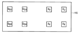
- the estimation method is described below. As illustrated in FIG. 7, when the module 115 in which the U phase of the inverter for electric motors and the U phase of the generator inverter are integrated is taken as an example, the number of mounted semiconductor elements is eight.
- the basic estimation method is the same as in the first and second embodiments, and only the target elements for temperature estimation are increased. First, the losses of all the elements are estimated by the equations (1) to (5).
- the detected current used for loss estimation uses the current value 19 detected by the current sensor 18 for the semiconductor element on the motor side, and the current value 107 detected by the current sensor 106 for the semiconductor element on the generator side.
- the heat transfer impedance of equation (8) is also measured in advance.
- Equation (12) is used as an equation representing the relationship between the temperature rise and loss in Equation (9).
- the temperature rise value of the semiconductor element mounted on the V and W phase modules can be obtained using the same equation.
- the junction temperature is calculated according to the equation (11).
- the maximum temperature T NMAX of the low side element of the inverter for the motor is used as a reference, and in this embodiment, T NMAX is also used as a reference.
- the temperature is also detected by the temperature sensor in the low-side element for the generator, and when the maximum temperature T NGMAX of the low-side element is obtained, the semiconductor element for the generator is expressed by the formula (11 ) To estimate.
- the loss (P GSU to P GDX ) of the generator in equation (12) is obtained by using the maximum temperature of the generator in the equations (1) to (5) of loss, and the temperature rise value from equation (12) ⁇ T is obtained, and the junction temperature is obtained by substituting the temperature increase value ⁇ T into equation (11).
- the temperature estimation accuracy increases.
- SYMBOLS 1 ... Accelerator apparatus, 2 ... Inverter, 4 ... DC voltage source, 5 ... Electric motor, 6 ... Wheel, 7 ... Capacitor, 8 ... Temperature detection circuit, 9 ... Low side element maximum temperature, 10 ... Control arithmetic unit, 11 ... Operational amplifier, DESCRIPTION OF SYMBOLS 12 ... Diode, 13 ... Triangular wave generation circuit, 14 ... Comparator, 15 ... Photocoupler, 16 ... Current control part, 17 ... Temperature estimation part, 18 ... Current detector, 19 ... Current value, 20 ... Angle detector, 21 ... Electrical angle, 22 ... gate signal, 23 ... gate drive circuit, 24 ... voltage detector, 25 ...
Landscapes
- Engineering & Computer Science (AREA)
- Power Engineering (AREA)
- Life Sciences & Earth Sciences (AREA)
- Sustainable Development (AREA)
- Sustainable Energy (AREA)
- Transportation (AREA)
- Mechanical Engineering (AREA)
- Inverter Devices (AREA)
- Electric Propulsion And Braking For Vehicles (AREA)
- Hybrid Electric Vehicles (AREA)
Abstract
直流電源4と、前記直流電源4に接続されたスイッチング素子Sおよび還流ダイオードDと、スイッチング素子Sのオン/オフによって直流電圧を所定の交流電圧、電流、周波数に変換する手段と、1つ以上のスイッチング素子近傍に設置した温度検出部Cを備えたインバータ装置2において、スイッチング素子Sおよび還流ダイオードDの損失モデル(式(1)~(5))と、前記スイッチング素子Sおよび還流ダイオードDを固定するモジュールの熱抵抗モデル(式(6)~(9))と、前記損失モデルおよび熱抵抗モデルを利用して算出された推定温度上昇値と、前記温度検出部Cで検出したスイッチング素子の温度とに基づいて、温度検出部を備えていないスイッチング素子および還流ダイオードの温度を推定する推定手段17を備える。インバータの運転モードによらず、1つのスイッチング素子から検出した温度を基に、他のスイッチング素子温度を推定する。
Description
本発明の実施形態は電動機を駆動するインバータ装置に関し、特にインバータを構成するスイッチング素子の温度を推定する技術に関する。
電動機は、エンジンと組み合わせたハイブリッド自動車、または電動機のみで駆動する電気自動車等に用いられる。電動機を駆動する際、所定のトルク、周波数を得るのにインバータが用いられる。インバータは自動車内に組み込まれ、搭乗スペースの確保のためにその高パワー高密度化が望まれている。
自動車の走行環境によってインバータの運転温度が大きく変動し、特にハイブリッド自動車においては、エンジンの発熱の影響でインバータは高温になる。インバータ内のスイッチング素子は、このような周囲温度に加えて、スイッチング素子自身に電流が流れることによる定常損失、オン・オフによるスイッチング損失の影響で温度が上昇し、ある温度を超えると破壊に至る恐れがある。
スイッチング素子の破壊を回避するために、スイッチング素子の温度を検出して保護を行う必要がある。温度検出には素子上にダイオードを作りこんだオンチップセンサを利用すると精度が高く検出できるので、このようなセンサがハイブリッド自動車用インバータに搭載されている。オンチップセンサは高電位になるため、絶縁回路を通してマイクロコントローラ(以下マイコン)などに温度情報を伝送する必要がある。少なくとも6個のスイッチング素子が搭載されているインバータにおいては、全てのスイッチング素子の温度を検出するために絶縁回路が複数必要となり、基板面積が増大してインバータ容積が大きくなる恐れがある。
このような課題を解決するために、一部のスイッチング素子のみ温度検出を行い、残りのスイッチング素子温度は推定する方法が考えられる。1つ以上のスイッチング素子温度を検出し、スイッチング素子の損失モデル、およびIGBTモジュールの熱伝達モデルから最高温度のスイッチング素子の温度を推定する方法が開示されている。
従来の方法においては、スイッチング素子の損失モデルおよび熱伝達モデルが、定常状態におけるものであり、モータがロックしたときや低周波で回転しているときのように、一部のスイッチング素子に電流が集中する状態に遷移するときは、最高温度となるスイッチング素子が確実に特定できず、スイッチング素子温度を精確に推定できない。また、最高温度と推定されるスイッチング素子周囲にあるスイッチング素子の温度推定値を基に、熱伝達モデルが構成されているために、基になるスイッチング素子温度の推定値に誤差がある場合には、最高温度を示すスイッチング素子温度の推定誤差が増大する。
本発明は上述した課題を解決するためになされたものであり、インバータの運転モードがどのような状態であっても、1つのスイッチング素子から検出した温度を基に、他のスイッチング素子温度を精確に推定することで、インバータ装置の部品点数及び基板スペースの削減を目的とする。
本発明の一実施例に係るインバータ装置は、直流電源と、直流電源に接続されたスイッチング素子および還流ダイオードと、スイッチング素子のオン/オフによって直流電圧を所定の交流電圧、電流、周波数に変換する手段と、1つ以上のスイッチング素子近傍に設置した温度検出部を備えたインバータ装置において、スイッチング素子および還流ダイオードの損失モデルと、前記スイッチング素子および還流ダイオードを固定するモジュールの熱抵抗モデルと、前記損失モデルおよび熱抵抗モデルを利用して算出された推定温度上昇値と、前記温度検出部で検出したスイッチング素子の温度とに基づいて、温度検出部を備えていないスイッチング素子および還流ダイオードの温度を推定する推定手段とを備える。
以下、本発明に係るインバータ装置の実施例について、図面を参照して説明する。
(構成)
図1は本発明によるインバータ装置を、電気自動車又はハイブリッド車等の電気車に適用したときの実施例の構成を示す図である。本発明によるインバータ装置は、電気車のみならず、電気推進船等にも適用できる。
図1は本発明によるインバータ装置を、電気自動車又はハイブリッド車等の電気車に適用したときの実施例の構成を示す図である。本発明によるインバータ装置は、電気車のみならず、電気推進船等にも適用できる。
このインバータ装置は、アクセル装置1からインバータ2にトルク指令値Tq*を入力し、トルク指令値Tq*に応じて、バッテリなどの直流電圧源4の出力電圧を可変電圧可変周波数の3相交流電圧に変換し、電動機5を駆動して車輪6を駆動制御する。
インバータ2は、直流電圧を平滑化するコンデンサ7が入力段に接続され、スイッチング素子によりU相、V相、W相のブリッジ回路を構成している。U相のブリッジ回路は、スイッチング素子SUとスイッチング素子SXの接続点が電動機5に接続されている。スイッチング素子SUとスイッチング素子SXには還流ダイオードDUとDXがそれぞれ逆並列に接続されている。
スイッチング素子SVとSY,還流ダイオードDVとDYで構成されるV相のブリッジ回路、スイッチング素子SWとSZ,還流ダイオードDWとDZで構成されるW相のブリッジ回路も同様に構成されている。
スイッチング素子SU、SX、SV、SY、SW、SZのいずれか1つまたは複数の近傍に温度センサが設けられる。本実施例においては、スイッチング素子SX、SY、SZのローサイド素子に温度センサCX,CY,CZをそれぞれ設置する。温度センサCX,CY,CZはスイッチング素子上に作り込まれたオンチップのダイオードとする。ダイオードは定電流の条件では、温度が上昇すると順方向電圧が小さくなる傾向にある。ダイオードに一定の電流を供給し、順方向電圧を測定することによって、スイッチング素子の温度が得られる。温度センサはダイオード以外のものでもよいが、応答性が高く、高精度のものが望ましい。
温度センサCX,CY,CZが出力した電圧は、温度検出回路8に入力される。そのうちの最も高い温度を示すスイッチング素子の温度信号9を制御演算装置10に伝達する。インバータの下レグ(アームとも呼ばれる)を構成するスイッチング素子SX、SY、SZは、電位が等しく互いの絶縁をとる必要がないので、最高温度TNMAXを示す温度信号を簡単に抽出できる。図2に最高温度TNMAXを選択する回路8aの一例を示す。本回路はオペアンプ11X、11Y、11Zとダイオード12X、12Y、12Zから成る最小値回路として一般的に用いられ、温度センサ電圧VfX、VfY、VfZのうち最も低い電圧を出力する。各オペアンプ入力に記載された丸印は反転入力端子であることを示す。ダイオードは温度が上昇すると順方向電圧が下がるので、最も低い電圧は最高温度TNMAXを示す信号となる。
出力した電圧は三角波発生回路13とコンパレータ14にて比較され、パルスに変換されてフォトカプラなどの絶縁素子15を通して制御演算装置10へ伝達される。制御演算装置10がパルスのデューティ比を計算することによって最高温度TNMAXを得る。図2では温度が上昇するほどデューティが小さくなるように回路を構成している。このように、伝達する信号が1つであれば、温度検出回路8に使用する絶縁素子が1個で足りるので回路規模が大きくならない。スイッチング素子SX、SY、SZのうちどれか1つの温度を常に検出してもよいが、最高温度を検出することでより信頼性の高い温度保護システムを提供できる。
制御演算装置10は、電流制御部16と温度推定部17で構成される。電流制御部16には電流検出器18から得られた三相電流瞬時値19と、電動機の角度検出器20から得られた電気角21が入力される。トルク指令値Tqb*に対応する電流指令値を電流制御部16で演算し、所望の電流を得るようなゲート信号22をゲート駆動回路23に出力する。ゲート駆動回路23はスイッチング素子SU、SX、SV、SY、SW、SZが有するゲートの全てに接続され、制御演算装置10から入力されたゲート信号22に応じてオン・オフの切り替えを行う。
温度推定部17には三相電流瞬時値19と直流電圧検出器24から得られる電圧値25、温度センサCX,CY,CZから得られるスイッチング素子温度のうちの最高スイッチング素子温度9が入力される。これらの物理量を基にして全てのスイッチング素子の温度、および還流ダイオードの温度を推定する。
以上がインバータ装置全体の構成である。
(作用)
図3は温度推定部17により行われる温度推定方法の概要を示すフローチャートである。先ず温度推定部17は、IGBT温度、直流電圧、相電流、デューティ比、キャリア周波数等を基に、IGBT及び還流ダイオード(FWD)全素子の損失を推定する(S10)。次に温度推定部17は、IGBTモジュール熱抵抗モデルに損失を入力することで、IGBT及びFWD全素子の温度上昇値を推定する(S20)。そして温度推定部17は、温度上昇推定値と検出温度の差から温度を推定する(S30)。また、検出されたあるIGBTの温度をベースとして、温度検出していないその他の素子の温度を算出する。
図3は温度推定部17により行われる温度推定方法の概要を示すフローチャートである。先ず温度推定部17は、IGBT温度、直流電圧、相電流、デューティ比、キャリア周波数等を基に、IGBT及び還流ダイオード(FWD)全素子の損失を推定する(S10)。次に温度推定部17は、IGBTモジュール熱抵抗モデルに損失を入力することで、IGBT及びFWD全素子の温度上昇値を推定する(S20)。そして温度推定部17は、温度上昇推定値と検出温度の差から温度を推定する(S30)。また、検出されたあるIGBTの温度をベースとして、温度検出していないその他の素子の温度を算出する。
以下に第1の実施例におけるスイッチング素子及び還流ダイオードの温度の推定方法を詳細に述べる。各素子の温度は自身の損失で発生する熱と、周囲の素子の損失がもたらす熱によって決まる。従って、先ずは各素子の損失を推定する必要がある。
最初に、スイッチング素子SU~SZの損失の推定方法を記述する。スイッチング素子の損失は、導通損失とスイッチング損失に分けることができる。先ず導通損失は、素子に流れる電流と素子自身の抵抗成分によって生じ、ジャンクション温度に依存するため、式(1)で表される。

ここで、IC=素子に流れる電流(瞬時値)、Tj=素子のジャンクション温度、DUTY=スイッチング素子の通流率を表す。電流ICは電流検出器18から得ることができる。Tjはこれから推定する温度なので得ることができないが、本実施例では温度センサで検出したローサイド素子の最高温度TNMAXを全ての素子に適用する。本実施例では、平均温度等ではなく、安全を見込んで最高温度に基づいて推定が行われる。関数fは電流ICと温度Tjの多項式で表され、制御演算装置10にあらかじめ記憶させておく。U相のレグを例にすると、U相電流IUが正の値であれば電流はスイッチング素子SUまたは還流ダイオードDXを流れ、負の値であればスイッチング素子SXまたは還流ダイオードDUを流れている。従って電流IUが正のとき、式(1)にIC=IUを代入してスイッチング素子SUの導通損失を求める。スイッチング素子SUはオン/オフしているので、オン期間の割合を示す通流率DUTYUを乗算すれば、スイッチング周期TSW期間における平均導通損失が求められる。このときスイッチング素子SXには電流が流れていないので、素子SXの導通損失はゼロとなる。逆に電流IUが負のとき、スイッチング素子Sxに電流が流れており、式(1)にIC=-IUを代入し、通流率DUTYXを乗算してその導通損失を求めることができる。もちろん、スイッチング素子SUのスイッチング損失はこのときゼロである。V、W相の各スイッチング素子の導通損失も同様に計算できる。スイッチング周期TSWは温度上昇の時定数に比べれば十分短い時間なので、式(1)で求められる損失は瞬時値として扱って問題ない。
一方、スイッチング損失はターンオン時に生じるオン損失PSWONとターンオフ時に生じるオフ損失PSWOFFの和であり、電圧と電流の重なり、つまりスイッチング素子に電圧と電流が同時に発生していることが損失の原因となる。これもジャンクション温度Tjに依存するので、それぞれ式(2)、(3)で表される。


ここで、VDC=直流電圧、fSW=スイッチング周波数を表す。電圧VDCは電圧検出器24から得る。これらの関数g、hは変数の多項式で記述でき、制御演算装置10に記憶されている。導通損失と同様に、素子に電流が流れないとスイッチング損失は生じない。再びU相のレグを例にとる。電流IUが正のとき、スイッチング素子SUに電流が流れているので、式(2)、(3)にIC=IUを代入してスイッチング素子SUのスイッチング損失を求める。スイッチング素子SXに電流は流れていないので、素子SXのスイッチング損失はゼロとなる。電流IUが負のとき、式(2)、(3)にIC=-IUを代入してスイッチング素子SXのスイッチング損失が求まる。このときのスイッチング素子SUのスイッチング損失はゼロである。V、W相のスイッチング素子のスイッチング損失も同様にして計算する。
スイッチング素子SU~SZそれぞれについて導通損失、スイッチング損失を求める。導通損失とスイッチング損失を合計したものが1つの素子で発生する損失となる。
次に、還流ダイオードから生じる損失の推定方法を述べる。互いに接続されたスイッチング素子及び還流ダイオードにおいて、スイッチング素子がオフした時に、サージ電圧が発生するのを防ぐために還流ダイオードが設けられている。従って、スイッチング素子のオフ期間中に還流ダイオードに電流が流れ、スイッチング素子がオン期間中はその還流ダイオードに電流は流れない。
還流ダイオードの損失は導通損失とリカバリ損失の和で計算する。導通損失の基本的な計算方法はスイッチング素子のときと同じである。つまり、電流とジャンクション温度の多項式で表される関数iを用いて式(4)で記述できる。

DUTYは、対になるスイッチング素子(例えば還流ダイオードDUに対してスイッチング素子SX)の通流率である。
U相レグを例にして説明する。還流ダイオードDXの導通損失を求めるには、U相電流IUが正のとき式(4)にIC=IUを代入する。スイッチング素子SUがオフの期間に還流ダイオードDXが通電するので、スイッチング素子SUのオフ期間の割合を示す1-DUTYUを乗算すればよい。このとき還流ダイオードDUには電流が流れていないので、還流ダイオードDUの導通損失はゼロとなる。U相電流IUが負のとき式(4)にIC=-IUを代入し、スイッチング素子SXのオフ期間の割合1-DUTYXを乗算することで、還流ダイオードDUの導通損失を求める。還流ダイオードDXは通電していないので、当然、還流ダイオードDXの導通損失はゼロとなる。
一方、リカバリ損失は還流ダイオードがオンからオフの状態に遷移するときに生じる損失であり、直流電圧、電流、ジャンクション温度に依存するので式(5)で計算できる。尚、還流ダイオードはオンするのに必要な時間は無視できるほど短いため、オフからオンするときの損失は無視できる。

関数jは3つの変数で構成される多項式である。リカバリ損失も還流ダイオードに電流が流れないとスイッチング損失は生じない。U相のレグを例にとって詳述する。電流IUが正のとき、還流ダイオードDXに電流が流れているので、式(5)にIC=IUを代入して還流ダイオードDXのリカバリ損失を求める。このとき還流ダイオードDUに電流は流れていないので、還流ダイオードDUのリカバリ損失はゼロとなる。電流IUが負のとき、式(5)にIC=-IUを代入して還流ダイオードDUのリカバリ損失が求まる。このとき還流ダイオードDXのリカバリ損失はゼロである。V、W相の還流ダイオードのリカバリ損失も同様に計算する。
還流ダイオードDU~DZそれぞれについて導通損失、リカバリ損失を求める。導通損失及びリカバリ損失を合計したものが1つの還流ダイオードで発生する損失となる。
以上の計算を行い、全てのスイッチング素子と還流ダイオードから発生する損失が求められる。
電動機が低周波数で駆動されているときは以上のような損失推定方法が可能であるが、高周波数で駆動されているときは、駆動周波数に比較して損失および温度推定に費やされる計算時間が十分に短くならない。例えば、駆動信号周波数の周期と計算時間が一致すると、計算周期ごとに同じ検出電流値を使用してしまうため、損失推定の精度が著しく悪化してしまう。
そこで、電動機が高周波数で駆動されているときは、損失推定に電流実効値Irmsを用いる。このとき、Mを変調率、φを力率とすると導通損失は式(6)で表すことができる。

オン損失PSWON、オフ損失PSWOFFおよびリカバリ損失Ptrrは、電流平均値を、
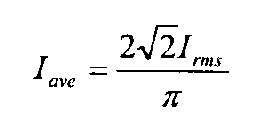
として、式(2)、(3)、(5)のICにこれを代入した上で2分の1を乗算して求められる。
損失計算方法の切り替えは、角度検出器によって得られた電気周波数で判断する。電気周波数が周波数fe未満のとき損失推定に電流瞬時値を用い、周波数fe以上のとき損失推定に電流実効値Irmsを用いる。周波数feの周期は計算周期およびスイッチング素子の熱時定数より十分短い周期とする。
次に、計算した損失を利用して、温度上昇値を求める過程を説明する。損失PLOSSと温度上昇値ΔTjは式(7)の関係にある。この温度上昇値ΔTjは、ジャンクション温度と周囲温度との差である。

PLOSSは温度上昇値ΔTjを計算する対象自身の損失であるが、モジュールは他の半導体素子と隣り合って構成されていることが多く、他の半導体素子から発生する損失の影響も受け、温度が上昇する。つまり、他の半導体素子からの影響も考慮して温度上昇値を求めることが、精度の高い温度推定には必要である。Zthは熱伝達インピーダンスと呼ばれ、スイッチング素子や還流ダイオードで構成されるモジュールの形状や材質で決定される。つまり、熱伝達インピーダンスZthは、シミュレーション又は実験により求められる。Zthは式(8)のような形で表される。

Rthは熱抵抗と呼ばれ、定常状態での損失と温度上昇値の関係を表す定数である。τは熱時定数といい、過渡状態での時間経過に対する温度上昇の割合を示す定数である。モジュールの形状や材質によってこれらの値と自然数nの値は決定される。ここでZthは、熱が伝わる物質の熱抵抗Rthと熱時定数τの並列回路で表わすことができる。例えばシリコンと胴を熱が伝わる場合、Zthはシリコンの熱インピーダンスと胴の熱インピーダンスの直列回路となる(n=2)。
ある半導体モジュールの構成例を図4に示し、この図を参照して温度上昇値の推定方法を説明する。図4の半導体モジュール26には、例としてU相レグを構成する半導体素子が搭載されており、各半導体素子と熱伝達インピーダンスの関係を示している。このとき、スイッチング素子SU、SXと還流ダイオードDU、DXの温度上昇値をそれぞれΔTSU、ΔTSX、ΔTDU、ΔTDXとおくと、式(9)が成り立つ。熱伝達インピーダンスZijは全て式(8)の形式であり、モジュール26の形状や材質、半導体素子の設置位置によって熱抵抗Rth、熱時定数τ、自然数nの値が決まる。これらZijは、制御演算装置10にあらかじめ記憶される。

V、W相の半導体モジュールを構成する各素子も、式(9)を使ってその温度上昇値が求められる。
このように全ての半導体素子の温度上昇値が求まったところで、実際のジャンクション温度を推定する。制御演算装置10に入力されるジャンクション温度は、ローサイド素子の最高温度TNMAXである。式(9)で計算されるローサイド素子の温度上昇値ΔTSX、ΔTSY、ΔTSZのなかで、最も値が大きいものがローサイド素子の最高温度上昇値ΔTNMAXを示す。環境温度をTaとおくと、式(10)が成り立つ。

つまり、ΔTNMAXは式(9)を用いて、温度計測されている各相のローサイドスイッチング素子の温度上昇値ΔTSX、ΔTSY、ΔTSZを計算し、そのなかで最も大きな値である。
例えば、スイッチング素子SUのジャンクション温度Tsuを推定したければ、式(11)で計算でき、環境温度Taの検出をする必要がない。このTsuは、スイッチング素子SUの現在のジャンクション温度推定値である。

同様にして、全てのスイッチング素子と還流ダイオードの温度を推定できる。
(効果)
従来においては、全ての半導体素子が同一モジュールに搭載されている場合の温度推定方法が開示されている。いずれか1つのスイッチング素子のみ温度検出し、かつこの検出温度を基準に温度推定している。そのため従来では、本実施例のようにU、V、W相ごとに異なるモジュールに分かれている場合には、他2相のモジュールの半導体素子については検出温度を基準に推定できない。本実施例では、ローサイド素子の最高温度TNMAXを検出しているため、少なくともローサイドにおいては確実に最高温度TNMAXを検出できる。
従来においては、全ての半導体素子が同一モジュールに搭載されている場合の温度推定方法が開示されている。いずれか1つのスイッチング素子のみ温度検出し、かつこの検出温度を基準に温度推定している。そのため従来では、本実施例のようにU、V、W相ごとに異なるモジュールに分かれている場合には、他2相のモジュールの半導体素子については検出温度を基準に推定できない。本実施例では、ローサイド素子の最高温度TNMAXを検出しているため、少なくともローサイドにおいては確実に最高温度TNMAXを検出できる。
しかしながら、基準とする温度をローサイド素子の最高温度TNMAXとせず、従来のように全スイッチング素子のうち何れか1つのジャンクション温度を検出しても、温度は推定できる。しかし最高温度を使用した方が、前述したように信頼性は高くなる。
従来においては、角度センサから得られた電気角の情報で最高温度となるスイッチング素子を推定している。本実施例のように還流ダイオードを含めたモジュールにおいては、熱干渉が複雑になり、電気角のみで最高温度となるスイッチング素子を推定することは困難となる。
また、従来のような各素子の推定温度を基準とする単なる熱干渉モデルとは異なり、本願では損失を基準とした熱干渉モデルを用いているため、温度検出対象となっている素子(最高温度を記録している素子)が含まれる相以外の相においても、精確に温度上昇値が推定できる。
さらに、従来は熱伝達インピーダンスが熱抵抗成分のみで構成されているため、過渡状態における温度変化に追従できない。例えば、図5を基に説明すると、時間T0の時点で急激に電流27が増大したときは、実際は熱容量の影響で緩やかに変化する真の温度28に対して、推定温度29が電流に依存して急に高くなるために、真の温度28より高く推定してしまう。時間T1で電流が減少したときには、真の温度より推定温度が低くなり、信頼性が損なわれる。
本実施例によれば、モジュールの構成、運転モード、遷移状態に依存することなく、全てのスイッチング素子と還流ダイオードのジャンクション温度が精確に推定できるため、確実な保護を行うことができ、信頼性の高いインバータ装置を提供できる。
次に、本発明に係るインバータ装置の第2実施例について記述する。本実施例においては、実施例1の損失推定方法に改良を加えたものである。よって、実施例1と同一の構成には同一の符号を付し、重複する説明は省略する。
実施例1においては、式(1)~(5)の損失計算に用いたTjに温度センサで検出したローサイド素子の最高温度TNMAXを代入していた。制御演算装置10を使った演算では、制御周期TCTRLごとに繰り返し温度計算を行っているため、制御周期(TCTRL)前に求めた各素子の推定温度を使用して現在の温度を推定できる。一律に最高温度TNMAXを使用して損失を推定するよりも、実際に即した各スイッチング素子、および還流ダイオードの推定温度を用いれば、損失がより精確(実際に近い値)に推定でき、温度推定精度も高くなる。推定する瞬間の真の温度と、損失の推定に使用する制御周期TCTRL前の推定温度を近くするために、制御周期TCTRLは半導体素子の熱時定数より十分短くする必要がある。
次に本発明に係るインバータ装置の第3実施例について述べる。本実施例は、走行用の電動機を駆動するインバータと、エンジンが駆動する発電機用のインバータを搭載するシリパラ方式のハイブリッド自動車に適用する。シリパラ方式のハイブリッド自動車は、インバータが2台搭載されているため、設置スペースを削減するために2台のインバータを一体化する場合がある。このとき、半導体素子で構成されるモジュールに電動機用の半導体素子と発電機用の半導体素子が搭載されるため、互いにその発熱の影響を受ける。実施例1,2においては、電動機用のインバータに限った温度推定であるが、本実施例のように発電機用の半導体素子の発熱の影響を受ける場合には、温度推定誤差が生じる。
図6に本実施例の構成例を示す。実施例1と同一の構成には同一の符号を付し、重複する説明は省略する。電動機5を駆動するインバータは実施例1と全く同じ構成である。発電機用のインバータは、コンデンサ101、スイッチング素子SGU、SGV、SGW、SGX、SGY、SGZと還流ダイオードDGU、DGV、DGW、DGX、DGY、DGZで構成される。エンジン102で駆動する発電機103と接続され、電力を直流電圧源4へ回生する。制御演算装置11には発電機用の電流制御部104を追加する。ハイブリッド自動車からバッテリ(直流電圧源4)の充電状態に応じて指令される電流指令値I*105に従い、電流制御部は電流センサ106で検出した電流値107と、発電機の角度センサ108から検出される電気角109からスイッチング素子のゲート信号110を生成する。ゲート信号110はゲート駆動回路111に入力され、スイッチング素子のオン/オフが行われる。電動機用インバータと同様に、発電機用インバータの温度検出はローサイドの最高温度素子を検出する。温度検出回路112の構成も電動機用インバータの温度検出回路9と同じである。
温度推定部113は電動機用および発電機用インバータの全ての半導体素子のジャンクション温度を推定する。そのため、発電機用の電流値107とローサイドの最高温度素子温度114が温度推定部113で使用される。以下、推定方法を記述する。図7のように、電動機用インバータのU相と発電機用インバータのU相が一体化したモジュール115を例にとると、搭載される半導体素子数は8個となる。基本的な推定方法は実施例1,2と同じであり、温度推定の対象素子が増加しただけである。まずは、式(1)~(5)で全ての素子の損失を推定する。ただし、損失推定に利用する検出電流は、電動機側の半導体素子は電流センサ18で検出した電流値19を用いて、発電機側の半導体素子は電流センサ106で検出した電流値107を用いる。式(8)の熱伝達インピーダンスもあらかじめ測定しておく。式(9)の温度上昇と損失の関係を表した式は、式(12)を用いることになる。

V,W相のモジュールに搭載されている半導体素子の温度上昇値も同様の式を用いて求めることができる。
温度上昇値を求めたところで、式(11)に従ってジャンクション温度を計算する。実施例1,2では、電動機用インバータのローサイド素子の最高温度TNMAXを基準としており、本実施例でもTNMAXを基準とする。ただし、発電機用のローサイド素子にも温度センサによる温度検出がなされており、ローサイド素子の最高温度TNGMAXが得られるときは、発電機用の半導体素子は最高温度TNGMAXを基準として式(11)を使って推定する。つまり、式(12)の発電機の損失(PGSU~PGDX)は、損失の式(1)~(5)に発電機の最高温度を使用して求め、式(12)から温度上昇値ΔTを求めて、式(11)に温度上昇値ΔTを代入して、ジャンクション温度を求める。このように、温度推定の対象となる半導体素子と、基準となる温度を検出する素子の位置関係を近くすれば、温度推定精度が高くなる。
以上の説明はこの発明の実施の形態であって、この発明の装置及び方法を限定するものではなく、様々な変形例を容易に実施することができるものである。
1…アクセル装置、2…インバータ、4…直流電圧源、5…電動機、6…車輪、7…コンデンサ、8…温度検出回路、9…ローサイド素子最高温度、10…制御演算装置、11…オペアンプ、12…ダイオード、13…三角波発生回路、14…コンパレータ、15…フォトカプラ、16…電流制御部、17…温度推定部、18…電流検出器、19…電流値、20…角度検出器、21…電気角、22…ゲート信号、23…ゲート駆動回路、24…電圧検出器、25…電圧値、26…半導体モジュール、27…電流値、28…真のスイッチング素子の温度、29…推定したスイッチング素子の温度101…コンデンサ、102…エンジン、103…発電機、104…電流制御部、105…電流指令値、106…電流検出器、107…電流値、108…角度検出器、109…電気角、110…ゲート信号、111…ゲート駆動回路、112…温度検出回路、113…温度推定部、114…ローサイド素子最高温度、115…半導体モジュール。
Claims (7)
- 直流電源と、前記直流電源に接続されたスイッチング素子および還流ダイオードと、前記スイッチング素子のオン/オフによって直流電圧を所定の交流電圧、電流、周波数に変換する手段と、1つ以上のスイッチング素子近傍に設置した温度検出部を備えたインバータ装置において、
前記スイッチング素子および還流ダイオードの損失モデルと、前記スイッチング素子および還流ダイオードを固定するモジュールの熱抵抗モデルと、前記損失モデルおよび熱抵抗モデルを利用して算出された推定温度上昇値と、前記温度検出部で検出したスイッチング素子の温度とに基づいて、温度検出部を備えていないスイッチング素子および還流ダイオードの温度を推定する推定手段を備えることを特徴とするインバータ装置。 - 前記温度検出部は、前記インバータ装置を構成する低電位側のスイッチング素子に設置され、該スイッチング素子の温度のうち最も高い温度を選択して前記推定手段に入力する手段を備えることを特徴とする請求項1記載のインバータ装置。
- 前記推定手段は、
前記スイッチング素子の損失モデルを、導通損失aとスイッチング損失との和とし、
前記導通損失aをスイッチング素子に流れる電流瞬時値と、電流通流率と、前記温度検出部で検出されたスイッチング素子の温度とで表される多項式で算出される値とし、
前記スイッチング損失をスイッチング素子および還流ダイオードに流れる電流瞬時値と、電流通流率と、前記直流電圧と、前記温度検出部で検出されたスイッチング素子の温度とで表す多項式で算出される値とし、
前記還流ダイオードの損失モデルを、導通損失bとリカバリ損失との和とし、
前記導通損失bを還流ダイオードに流れる電流瞬時値と、電流通流率と、前記温度検出部で検出したスイッチング素子の温度とで表す多項式で算出する値とし、
前記リカバリ損失を還流ダイオードに流れる電流瞬時値と、電流通流率と、前記直流電圧と、前記温度検出部で検出したスイッチング素子の温度とで表す多項式で算出する値とすることを特徴とする請求項1記載のインバータ装置。 - 前記推定手段は、
インバータの出力周波数がある周波数以下であるときにおいて、前記損失モデルを用いてスイッチング素子および還流ダイオードの温度を推定し、
インバータの出力周波数が前記ある周波数を超えたときにおいて、
前記スイッチング素子の損失モデルを、導通損失aとスイッチング損失との和とし、
導通損失aをスイッチング素子に流れる電流実効値と、前記温度検出部で検出されたスイッチング素子の温度とで表される多項式eで算出される値とし、
スイッチング損失をスイッチング素子および還流ダイオードに流れる電流実効値と、前記直流電圧と、前記温度検出部で検出されたスイッチング素子の温度とで表す多項式fで算出される値とし、
前記還流ダイオードの損失モデルを、導通損失bとリカバリ損失との和とし、
前記導通損失bを還流ダイオードに流れる電流実効値と、前記温度検出部で検出したスイッチング素子の温度とで表す多項式gで算出する値とし、
前記リカバリ損失を還流ダイオードに流れる電流実効値と、前記直流電圧と、前記温度検出部で検出したスイッチング素子の温度とで表す多項式hで算出する値とすることを特徴とする請求項3記載のインバータ装置。 - 前記推定手段は、前記モジュールの熱抵抗モデルを、全てのスイッチング素子および還流ダイオード自身と冷却器との間にある熱抵抗と、全てのスイッチング素子および還流ダイオードとで互いに生じる熱干渉によるものとし、自身の熱抵抗および互いに及ぼす熱干渉を熱抵抗および熱容量で表すことを特徴とする請求項1記載のインバータ装置。
- 前記スイッチング素子および還流ダイオードの損失を求める多項式に用いる温度検出部で検出したスイッチング素子の温度を、直前に推定した該スイッチング素子の温度および還流ダイオードの温度とすることを特徴とする請求項2記載のインバータ装置。
- 前記インバータ装置は、シリパラ方式のハイブリッド自動車に搭載される、走行用の電動機を駆動するインバータを構成するスイッチング素子と、エンジンが駆動する発電機用のインバータを構成するスイッチング素子とが一体化しているモジュールを備えるインバータ装置であって、
前記推定手段は、前記発電機用インバータのスイッチング素子および還流ダイオードで発生する損失を推定し、電動機用インバータと発電機用インバータとが発生する損失によって互いに及ぼす影響を考慮して温度上昇値を推定することを特徴とする請求項1乃至5のうち1項記載のインバータ装置。
Priority Applications (3)
| Application Number | Priority Date | Filing Date | Title |
|---|---|---|---|
| EP10826755.0A EP2498391B1 (en) | 2009-11-02 | 2010-10-27 | Inverter device |
| CN201080036867.2A CN102474198B (zh) | 2009-11-02 | 2010-10-27 | 逆变器装置 |
| US13/461,201 US8582335B2 (en) | 2009-11-02 | 2012-05-01 | Inverter apparatus |
Applications Claiming Priority (2)
| Application Number | Priority Date | Filing Date | Title |
|---|---|---|---|
| JP2009252332A JP5443946B2 (ja) | 2009-11-02 | 2009-11-02 | インバータ装置 |
| JP2009-252332 | 2009-11-02 |
Related Child Applications (1)
| Application Number | Title | Priority Date | Filing Date |
|---|---|---|---|
| US13/461,201 Continuation US8582335B2 (en) | 2009-11-02 | 2012-05-01 | Inverter apparatus |
Publications (1)
| Publication Number | Publication Date |
|---|---|
| WO2011052623A1 true WO2011052623A1 (ja) | 2011-05-05 |
Family
ID=43922048
Family Applications (1)
| Application Number | Title | Priority Date | Filing Date |
|---|---|---|---|
| PCT/JP2010/069035 Ceased WO2011052623A1 (ja) | 2009-11-02 | 2010-10-27 | インバータ装置 |
Country Status (5)
| Country | Link |
|---|---|
| US (1) | US8582335B2 (ja) |
| EP (1) | EP2498391B1 (ja) |
| JP (1) | JP5443946B2 (ja) |
| CN (1) | CN102474198B (ja) |
| WO (1) | WO2011052623A1 (ja) |
Cited By (4)
| Publication number | Priority date | Publication date | Assignee | Title |
|---|---|---|---|---|
| WO2013014798A1 (ja) * | 2011-07-28 | 2013-01-31 | 三菱電機株式会社 | モータ制御装置 |
| CN102934344A (zh) * | 2010-06-03 | 2013-02-13 | 日产自动车株式会社 | 电力变换机的控制装置 |
| CN102957333A (zh) * | 2011-08-18 | 2013-03-06 | 三菱电机株式会社 | 半导体功率转换装置 |
| WO2019053825A1 (ja) * | 2017-09-13 | 2019-03-21 | 三菱電機株式会社 | エレベータの制御装置および制御方法 |
Families Citing this family (70)
| Publication number | Priority date | Publication date | Assignee | Title |
|---|---|---|---|---|
| CN103415992B (zh) * | 2011-02-25 | 2016-07-27 | Ntn株式会社 | 电动汽车 |
| JP5482694B2 (ja) * | 2011-03-08 | 2014-05-07 | 株式会社デンソー | 電力変換装置 |
| US9815193B2 (en) | 2011-06-27 | 2017-11-14 | Delaware Capital Formation, Inc. | Electric motor based holding control systems and methods |
| CA2879578A1 (en) * | 2012-08-03 | 2014-02-06 | Abb Schweiz Ag | Overload limitation in peak power operation |
| JP2014036475A (ja) * | 2012-08-08 | 2014-02-24 | Hitachi Automotive Systems Ltd | 電動パワートレインシステム |
| JP5927082B2 (ja) * | 2012-08-28 | 2016-05-25 | 本田技研工業株式会社 | 電動機の駆動装置 |
| JP5843735B2 (ja) * | 2012-09-24 | 2016-01-13 | 三菱電機株式会社 | インバータの過熱保護制御装置及びインバータの過熱保護制御方法 |
| KR102062018B1 (ko) * | 2012-11-14 | 2020-01-08 | 현대로템 주식회사 | 철도차량용 보조전원장치의 제어회로 및 방법 |
| WO2014091852A1 (ja) * | 2012-12-12 | 2014-06-19 | 富士電機株式会社 | 半導体チップ温度推定装置及び過熱保護装置 |
| CN102991374B (zh) * | 2012-12-15 | 2017-07-21 | 奇瑞新能源汽车技术有限公司 | 一种电动汽车电机控制器被动整流保护系统 |
| JP6339022B2 (ja) * | 2012-12-28 | 2018-06-06 | 三菱電機株式会社 | 半導体装置、自動車 |
| FI125501B (fi) * | 2013-02-14 | 2015-10-30 | Abb Technology Oy | Ohjausjärjestelmä puolijohdekytkimiä varten |
| JP2014187789A (ja) * | 2013-03-22 | 2014-10-02 | Fanuc Ltd | 異常検出機能を備えたモータ駆動装置 |
| US9891640B2 (en) * | 2013-06-14 | 2018-02-13 | Infineon Technologies Ag | Sensing element for semiconductor |
| DE102013212925A1 (de) | 2013-07-03 | 2015-01-08 | Zf Friedrichshafen Ag | Kontrollvorrichtung und Verfahren zum Überwachen einer Funktion eines Halbleiterbauelements während dessen Betrieb sowie Elektrische Baugruppe mit einer Kontrollvorrichtung |
| CN103346712B (zh) * | 2013-07-24 | 2015-07-08 | 东南大学 | 一种在线估算低速电流斩波控制模式中开关磁阻电机控制器下续流管温度的方法 |
| CN103457495B (zh) * | 2013-09-13 | 2014-12-10 | 青岛四方车辆研究所有限公司 | 动车组辅助变流器有互联线并联供电控制系统及控制方法 |
| WO2015035803A1 (zh) | 2013-09-13 | 2015-03-19 | 青岛四方车辆研究所有限公司 | 动车组辅助变流器有互联线并联供电控制系统及控制方法 |
| US9465074B2 (en) * | 2013-10-09 | 2016-10-11 | Ford Global Technologies, Llc | System and method for measuring switching loss associated with semiconductor switching devices |
| JP5907236B2 (ja) * | 2013-12-11 | 2016-04-26 | 株式会社デンソー | 温度検出装置 |
| JP6219154B2 (ja) | 2013-12-11 | 2017-10-25 | 新電元工業株式会社 | 温度検出装置 |
| KR102056156B1 (ko) | 2013-12-24 | 2019-12-16 | 현대자동차 주식회사 | 전기 차량의 인버터 보호 방법 |
| CN103701105A (zh) * | 2013-12-31 | 2014-04-02 | 深圳市英威腾电气股份有限公司 | 一种电力电子设备的热过载保护方法、装置及系统 |
| KR101646346B1 (ko) * | 2014-09-23 | 2016-08-05 | 현대자동차주식회사 | 모터 제어 장치 및 방법 |
| CN107306516B (zh) * | 2014-12-24 | 2019-08-20 | 东芝三菱电机产业系统株式会社 | 功率转换装置 |
| JP6091546B2 (ja) * | 2015-05-28 | 2017-03-08 | 三菱電機株式会社 | 回転電機制御装置 |
| JP6557517B2 (ja) | 2015-06-08 | 2019-08-07 | ルネサスエレクトロニクス株式会社 | 半導体集積回路装置および電子装置 |
| JP6549451B2 (ja) | 2015-09-02 | 2019-07-24 | ルネサスエレクトロニクス株式会社 | 半導体集積回路装置および電子装置 |
| US9608558B1 (en) * | 2015-09-14 | 2017-03-28 | Infineon Technologies Ag | Calculation of MOSFET switch temperature in motor control |
| JP2017060276A (ja) * | 2015-09-16 | 2017-03-23 | 富士電機株式会社 | 三相インバータ装置 |
| US9762146B2 (en) * | 2015-10-30 | 2017-09-12 | Faraday&Future Inc. | Methods and systems for interconnecting parallel IGBT modules |
| CA2947465A1 (en) * | 2015-11-18 | 2017-05-18 | General Electric Company | A system and method for fault ride through |
| CN108475997B (zh) * | 2015-12-10 | 2020-08-04 | 株式会社电装 | 信号传输电路 |
| CN108475998B (zh) * | 2015-12-18 | 2020-05-15 | 株式会社电装 | 电力转换装置的控制系统 |
| JP6332297B2 (ja) * | 2016-02-09 | 2018-05-30 | トヨタ自動車株式会社 | 電力変換装置 |
| JP6666174B2 (ja) * | 2016-03-10 | 2020-03-13 | 株式会社Soken | 電力変換装置 |
| CN105655984B (zh) * | 2016-03-28 | 2018-10-30 | 广州七喜智能设备有限公司 | 一种变频器中igbt过温保护方法 |
| JP6180576B1 (ja) * | 2016-04-12 | 2017-08-16 | 三菱電機株式会社 | Dc−dc電圧変換装置 |
| US10811985B2 (en) | 2016-08-26 | 2020-10-20 | General Electric Company | Power conversion system and an associated method thereof |
| US10309838B2 (en) * | 2016-09-08 | 2019-06-04 | Qualcomm Incorporated | Temporal temperature sensor position offset error correction |
| JP2018046647A (ja) * | 2016-09-14 | 2018-03-22 | サンデン・オートモーティブコンポーネント株式会社 | インバータ装置及びそれを備えた車両用電動圧縮機 |
| JP2018096888A (ja) * | 2016-12-15 | 2018-06-21 | ルネサスエレクトロニクス株式会社 | 電圧検出装置、それを備えた温度検出装置、電圧検出方法、及び、それを備えた温度検出方法 |
| KR102712333B1 (ko) * | 2016-12-15 | 2024-10-02 | 현대자동차주식회사 | 파워모듈의 정션온도 측정 방법 |
| CH714311A1 (de) * | 2017-11-08 | 2019-05-15 | Landis & Gyr Ag | Schaltsystem für einen Stromzähler und Verfahren zum Schalten eines Schalters. |
| JP6753837B2 (ja) * | 2017-12-18 | 2020-09-09 | 株式会社東芝 | インバータ装置、及びインバータ装置の放熱特性検出方法 |
| US11323032B2 (en) * | 2017-12-28 | 2022-05-03 | Shindengen Electric Manufacturing Co., Ltd. | Plural power modules conversion device with switch element control |
| JP6753883B2 (ja) * | 2018-03-19 | 2020-09-09 | 株式会社東芝 | 検査装置、検査方法、検査プログラムおよびインバータ装置 |
| JP7091800B2 (ja) * | 2018-04-16 | 2022-06-28 | 株式会社デンソー | 回路基板 |
| EP3627675A1 (en) | 2018-09-21 | 2020-03-25 | Maschinenfabrik Reinhausen GmbH | Analyzing an operating condition of a power converter |
| JP7061060B2 (ja) * | 2018-12-20 | 2022-04-27 | ルネサスエレクトロニクス株式会社 | 制御回路、駆動システムおよびインバータの制御方法 |
| DE102019101163B3 (de) * | 2019-01-17 | 2020-06-04 | Schaeffler Technologies AG & Co. KG | Elektrische Antriebseinheit und Verfahren zur Temperaturberechnung in einer elektrischen Antriebseinheit |
| CN110098635B (zh) * | 2019-04-17 | 2022-06-28 | 华为数字能源技术有限公司 | 一种光伏逆变器以及相应开关频率控制的方法 |
| DE102020002352A1 (de) * | 2019-04-25 | 2020-10-29 | Fanuc Corporation | Motorantriebsvorrichtung mit Energiespeicher |
| JP6847158B2 (ja) * | 2019-05-31 | 2021-03-24 | 三菱電機株式会社 | 電力変換装置 |
| JP7181851B2 (ja) * | 2019-12-13 | 2022-12-01 | 日立Astemo株式会社 | 電力変換装置 |
| KR20210129855A (ko) * | 2020-04-21 | 2021-10-29 | 현대자동차주식회사 | 무선 충전 장치, 차량용 무선 충전 시스템 및 그 제어 방법 |
| JP7472663B2 (ja) * | 2020-06-05 | 2024-04-23 | 富士電機株式会社 | 電力変換装置 |
| JP7494041B2 (ja) * | 2020-07-29 | 2024-06-03 | 株式会社日立産機システム | 電力変換装置および遠隔監視システム |
| JP7385538B2 (ja) * | 2020-07-31 | 2023-11-22 | 株式会社安川電機 | 電力変換装置、温度推定方法及びプログラム |
| DE112021003307T5 (de) * | 2020-08-25 | 2023-04-20 | Sanden Corporation | Wechselrichtervorrichtung und damit ausgerüsteter elektrischer kompressor für fahrzeuge |
| EP3979480A1 (de) * | 2020-10-01 | 2022-04-06 | Siemens Aktiengesellschaft | Anordnung und verfahren zum ermitteln von temperaturen elektronischer bauelemente |
| CN115603604A (zh) * | 2021-07-08 | 2023-01-13 | 法雷奥西门子新能源汽车德国有限责任公司(De) | 逆变器以及半导体开关的内部温度的估算 |
| CN114398809B (zh) * | 2021-12-17 | 2025-09-19 | 中车永济电机有限公司 | 一种考虑散热器的igbt模块结温计算方法 |
| WO2023190776A1 (ja) | 2022-03-29 | 2023-10-05 | ニデック株式会社 | 電力変換装置、推定プログラム及び推定方法 |
| JP7254230B1 (ja) * | 2022-03-29 | 2023-04-07 | 三菱電機株式会社 | 電力変換装置 |
| DE102022208136A1 (de) * | 2022-08-04 | 2024-02-15 | Zf Friedrichshafen Ag | Verfahren und Vorrichtung zum Bestimmen einer Halbleitertemperatur eines Halbleiterelements, Stromrichter, elektrischer Achsantrieb und Kraftfahrzeug |
| CN118826584B (zh) * | 2023-12-26 | 2025-11-04 | 比亚迪股份有限公司 | 电机控制方法、存储介质、控制器及电机 |
| WO2025162313A1 (zh) * | 2024-01-31 | 2025-08-07 | 台达电子工业股份有限公司 | 电源供应装置 |
| DE102024108004A1 (de) * | 2024-03-20 | 2025-09-25 | Schaeffler Technologies AG & Co. KG | Leistungselektronik sowie elektrische Maschine |
| CN118584284B (zh) * | 2024-08-05 | 2025-07-01 | 清华大学 | 功率半导体特性测试回路、方法、系统、设备及存储介质 |
Citations (4)
| Publication number | Priority date | Publication date | Assignee | Title |
|---|---|---|---|---|
| JP2007195343A (ja) | 2006-01-19 | 2007-08-02 | Nissan Motor Co Ltd | インバータ装置 |
| JP2009171702A (ja) * | 2008-01-15 | 2009-07-30 | Toyota Motor Corp | 車両駆動システム |
| JP2009229128A (ja) * | 2008-03-19 | 2009-10-08 | Hitachi Ltd | インバータ回路の温度センサ診断装置 |
| JP2009232656A (ja) * | 2008-03-25 | 2009-10-08 | Mitsubishi Electric Corp | パワーモジュール、車載用電力変換装置、及び車両制御装置 |
Family Cites Families (7)
| Publication number | Priority date | Publication date | Assignee | Title |
|---|---|---|---|---|
| JPH07234162A (ja) * | 1994-02-24 | 1995-09-05 | Toshiba Corp | 電力変換器の温度検出装置 |
| US6483271B1 (en) * | 2000-11-14 | 2002-11-19 | Otis Elevator Company | Motor drive parameters |
| US6747884B2 (en) * | 2001-04-13 | 2004-06-08 | Mitsubishi Denki Kabushiki Kaisha | Power converter device |
| JP4665569B2 (ja) * | 2004-11-30 | 2011-04-06 | トヨタ自動車株式会社 | 電圧変換装置および電圧変換装置における電圧変換の制御をコンピュータに実行させるためのプログラムを記録したコンピュータ読取り可能な記録媒体 |
| US7791300B2 (en) * | 2005-09-21 | 2010-09-07 | Mitsubishi Denki Kabushiki Kaisha | Excessive temperature detecting system of electric motor controller |
| JP4710588B2 (ja) * | 2005-12-16 | 2011-06-29 | トヨタ自動車株式会社 | 昇圧コンバータの制御装置 |
| US8148929B2 (en) * | 2008-09-30 | 2012-04-03 | Rockwell Automation Technologies, Inc. | Power electronic module IGBT protection method and system |
-
2009
- 2009-11-02 JP JP2009252332A patent/JP5443946B2/ja active Active
-
2010
- 2010-10-27 CN CN201080036867.2A patent/CN102474198B/zh active Active
- 2010-10-27 EP EP10826755.0A patent/EP2498391B1/en active Active
- 2010-10-27 WO PCT/JP2010/069035 patent/WO2011052623A1/ja not_active Ceased
-
2012
- 2012-05-01 US US13/461,201 patent/US8582335B2/en active Active
Patent Citations (4)
| Publication number | Priority date | Publication date | Assignee | Title |
|---|---|---|---|---|
| JP2007195343A (ja) | 2006-01-19 | 2007-08-02 | Nissan Motor Co Ltd | インバータ装置 |
| JP2009171702A (ja) * | 2008-01-15 | 2009-07-30 | Toyota Motor Corp | 車両駆動システム |
| JP2009229128A (ja) * | 2008-03-19 | 2009-10-08 | Hitachi Ltd | インバータ回路の温度センサ診断装置 |
| JP2009232656A (ja) * | 2008-03-25 | 2009-10-08 | Mitsubishi Electric Corp | パワーモジュール、車載用電力変換装置、及び車両制御装置 |
Cited By (6)
| Publication number | Priority date | Publication date | Assignee | Title |
|---|---|---|---|---|
| CN102934344A (zh) * | 2010-06-03 | 2013-02-13 | 日产自动车株式会社 | 电力变换机的控制装置 |
| CN102934344B (zh) * | 2010-06-03 | 2015-08-26 | 日产自动车株式会社 | 电力变换机的控制装置 |
| WO2013014798A1 (ja) * | 2011-07-28 | 2013-01-31 | 三菱電機株式会社 | モータ制御装置 |
| JPWO2013014798A1 (ja) * | 2011-07-28 | 2015-02-23 | 三菱電機株式会社 | モータ制御装置 |
| CN102957333A (zh) * | 2011-08-18 | 2013-03-06 | 三菱电机株式会社 | 半导体功率转换装置 |
| WO2019053825A1 (ja) * | 2017-09-13 | 2019-03-21 | 三菱電機株式会社 | エレベータの制御装置および制御方法 |
Also Published As
| Publication number | Publication date |
|---|---|
| EP2498391A1 (en) | 2012-09-12 |
| JP5443946B2 (ja) | 2014-03-19 |
| EP2498391A4 (en) | 2018-02-28 |
| CN102474198A (zh) | 2012-05-23 |
| CN102474198B (zh) | 2014-10-01 |
| JP2011097812A (ja) | 2011-05-12 |
| EP2498391B1 (en) | 2020-04-15 |
| US8582335B2 (en) | 2013-11-12 |
| US20120217795A1 (en) | 2012-08-30 |
Similar Documents
| Publication | Publication Date | Title |
|---|---|---|
| JP5443946B2 (ja) | インバータ装置 | |
| CN101983322B (zh) | 温度检测电路 | |
| CN104736981B (zh) | 半导体芯片温度推定装置及过热保护装置 | |
| JP6274077B2 (ja) | モータ制御装置 | |
| CN100589315C (zh) | 具有过热检测功能的电动机控制装置 | |
| JP6557517B2 (ja) | 半導体集積回路装置および電子装置 | |
| CN111355440B (zh) | 控制电路、电驱动系统、逆变器系统及其控制方法 | |
| JP6443253B2 (ja) | 電力変換器制御装置 | |
| WO2011162318A1 (ja) | 電力変換装置およびその温度上昇演算方法 | |
| JP6217554B2 (ja) | インバータ装置 | |
| CN102957333B (zh) | 半导体功率转换装置 | |
| CN106877779B (zh) | 电力变换装置 | |
| JP2017534240A (ja) | コンバータおよびコンバータを作動する方法 | |
| JP2013258857A (ja) | 半導体モジュール及びその制御方法 | |
| US12237785B2 (en) | Electrical power conversion apparatus | |
| JP7181851B2 (ja) | 電力変換装置 | |
| JP6129260B2 (ja) | 通電装置、電動機制御装置、通電方法 | |
| JP2017103840A (ja) | インバータ装置 | |
| JP2013048515A (ja) | 電気自動車 | |
| JP2016093074A (ja) | インバータシステム | |
| JP6428412B2 (ja) | 電圧コンバータ制御装置 | |
| US12506403B2 (en) | Electric-power conversion apparatus |
Legal Events
| Date | Code | Title | Description |
|---|---|---|---|
| WWE | Wipo information: entry into national phase |
Ref document number: 201080036867.2 Country of ref document: CN |
|
| 121 | Ep: the epo has been informed by wipo that ep was designated in this application |
Ref document number: 10826755 Country of ref document: EP Kind code of ref document: A1 |
|
| WWE | Wipo information: entry into national phase |
Ref document number: 2010826755 Country of ref document: EP |
|
| NENP | Non-entry into the national phase |
Ref country code: DE |