WO2011052642A1 - チャンバ付騒音低減装置 - Google Patents
チャンバ付騒音低減装置 Download PDFInfo
- Publication number
- WO2011052642A1 WO2011052642A1 PCT/JP2010/069079 JP2010069079W WO2011052642A1 WO 2011052642 A1 WO2011052642 A1 WO 2011052642A1 JP 2010069079 W JP2010069079 W JP 2010069079W WO 2011052642 A1 WO2011052642 A1 WO 2011052642A1
- Authority
- WO
- WIPO (PCT)
- Prior art keywords
- chamber
- jet
- peripheral wall
- flow
- noise reduction
- Prior art date
- Legal status (The legal status is an assumption and is not a legal conclusion. Google has not performed a legal analysis and makes no representation as to the accuracy of the status listed.)
- Ceased
Links
Images



Classifications
-
- F—MECHANICAL ENGINEERING; LIGHTING; HEATING; WEAPONS; BLASTING
- F02—COMBUSTION ENGINES; HOT-GAS OR COMBUSTION-PRODUCT ENGINE PLANTS
- F02K—JET-PROPULSION PLANTS
- F02K1/00—Plants characterised by the form or arrangement of the jet pipe or nozzle; Jet pipes or nozzles peculiar thereto
- F02K1/28—Plants characterised by the form or arrangement of the jet pipe or nozzle; Jet pipes or nozzles peculiar thereto using fluid jets to influence the jet flow
- F02K1/34—Plants characterised by the form or arrangement of the jet pipe or nozzle; Jet pipes or nozzles peculiar thereto using fluid jets to influence the jet flow for attenuating noise
-
- F—MECHANICAL ENGINEERING; LIGHTING; HEATING; WEAPONS; BLASTING
- F02—COMBUSTION ENGINES; HOT-GAS OR COMBUSTION-PRODUCT ENGINE PLANTS
- F02C—GAS-TURBINE PLANTS; AIR INTAKES FOR JET-PROPULSION PLANTS; CONTROLLING FUEL SUPPLY IN AIR-BREATHING JET-PROPULSION PLANTS
- F02C6/00—Plural gas-turbine plants; Combinations of gas-turbine plants with other apparatus; Adaptations of gas-turbine plants for special use
- F02C6/04—Gas-turbine plants providing heated or pressurised working fluid for other apparatus, e.g. without mechanical power output
- F02C6/06—Gas-turbine plants providing heated or pressurised working fluid for other apparatus, e.g. without mechanical power output providing compressed gas
- F02C6/08—Gas-turbine plants providing heated or pressurised working fluid for other apparatus, e.g. without mechanical power output providing compressed gas the gas being bled from the gas-turbine compressor
-
- F—MECHANICAL ENGINEERING; LIGHTING; HEATING; WEAPONS; BLASTING
- F02—COMBUSTION ENGINES; HOT-GAS OR COMBUSTION-PRODUCT ENGINE PLANTS
- F02K—JET-PROPULSION PLANTS
- F02K1/00—Plants characterised by the form or arrangement of the jet pipe or nozzle; Jet pipes or nozzles peculiar thereto
- F02K1/38—Introducing air inside the jet
-
- F—MECHANICAL ENGINEERING; LIGHTING; HEATING; WEAPONS; BLASTING
- F02—COMBUSTION ENGINES; HOT-GAS OR COMBUSTION-PRODUCT ENGINE PLANTS
- F02K—JET-PROPULSION PLANTS
- F02K1/00—Plants characterised by the form or arrangement of the jet pipe or nozzle; Jet pipes or nozzles peculiar thereto
- F02K1/44—Nozzles having means, e.g. a shield, reducing sound radiation in a specified direction
-
- F—MECHANICAL ENGINEERING; LIGHTING; HEATING; WEAPONS; BLASTING
- F02—COMBUSTION ENGINES; HOT-GAS OR COMBUSTION-PRODUCT ENGINE PLANTS
- F02K—JET-PROPULSION PLANTS
- F02K1/00—Plants characterised by the form or arrangement of the jet pipe or nozzle; Jet pipes or nozzles peculiar thereto
- F02K1/46—Nozzles having means for adding air to the jet or for augmenting the mixing region between the jet and the ambient air, e.g. for silencing
-
- F—MECHANICAL ENGINEERING; LIGHTING; HEATING; WEAPONS; BLASTING
- F02—COMBUSTION ENGINES; HOT-GAS OR COMBUSTION-PRODUCT ENGINE PLANTS
- F02K—JET-PROPULSION PLANTS
- F02K1/00—Plants characterised by the form or arrangement of the jet pipe or nozzle; Jet pipes or nozzles peculiar thereto
- F02K1/52—Nozzles specially constructed for positioning adjacent to another nozzle or to a fixed member, e.g. fairing
-
- F—MECHANICAL ENGINEERING; LIGHTING; HEATING; WEAPONS; BLASTING
- F05—INDEXING SCHEMES RELATING TO ENGINES OR PUMPS IN VARIOUS SUBCLASSES OF CLASSES F01-F04
- F05D—INDEXING SCHEME FOR ASPECTS RELATING TO NON-POSITIVE-DISPLACEMENT MACHINES OR ENGINES, GAS-TURBINES OR JET-PROPULSION PLANTS
- F05D2220/00—Application
- F05D2220/30—Application in turbines
- F05D2220/32—Application in turbines in gas turbines
- F05D2220/323—Application in turbines in gas turbines for aircraft propulsion, e.g. jet engines
-
- F—MECHANICAL ENGINEERING; LIGHTING; HEATING; WEAPONS; BLASTING
- F05—INDEXING SCHEMES RELATING TO ENGINES OR PUMPS IN VARIOUS SUBCLASSES OF CLASSES F01-F04
- F05D—INDEXING SCHEME FOR ASPECTS RELATING TO NON-POSITIVE-DISPLACEMENT MACHINES OR ENGINES, GAS-TURBINES OR JET-PROPULSION PLANTS
- F05D2260/00—Function
- F05D2260/96—Preventing, counteracting or reducing vibration or noise
Definitions
- the present invention relates to a noise reduction device used for an aircraft jet engine.
- This application claims priority based on Japanese Patent Application No. 2009-247780 filed in Japan on October 28, 2009, the contents of which are incorporated herein by reference.
- An aircraft jet engine includes a fan that takes in air, a compressor that takes in and compresses a portion of the air taken in by the fan, and a combustor that mixes and burns compressed air and fuel generated by the compressor.
- the fan and the turbine that drives the compressor are sequentially arranged by the combustion gas of the combustor.
- the compressor, the combustor, and the turbine are installed in a main nozzle that is a cylindrical partition wall, and the fan is installed on the upstream side of the main nozzle.
- Most of the air taken in by the fan passes through a bypass passage provided between the casing (engine nacelle) covering the outer periphery of the main nozzle.
- the air (bypass flow) that has passed through the bypass channel is discharged so as to surround the outer periphery of the turbine core flow (jet flow), and merges with the jet flow.
- a region where the jet flow and the bypass flow merge serves as a noise generation source to generate noise.
- Various techniques have been disclosed for reducing this noise. For example, a technique is disclosed in which a micro jet nozzle is provided at the ejection side periphery of the main nozzle, and the micro jet is ejected from the micro jet nozzle toward the junction of the jet flow and the bypass flow (for example, see Non-Patent Document 1). ).
- the micro jet nozzle communicates with the fan section or the compressor in the jet engine through a pipe laid around the main nozzle. And a part of compressed air produced
- Patent Document 1 discloses a system and method for reducing exhaust noise of a jet engine nozzle having a protrusion (chevron).
- a first flow of gas is generated by a jet engine, and the first flow is delivered through a nozzle having a trailing edge circumference including a plurality of protrusions extending in the rear direction, and is pressurized.
- Patent Document 2 discloses an apparatus for reducing jet engine exhaust noise using a vibrating jet.
- the piping that guides the compressed air may expand due to the heat of the jet engine, and may be damaged or the injection position may be shifted. Further, a cavity flow is generated around the pipe, and fluid noise is generated, or additional noise accompanying vibration of the pipe is generated. And the operation
- Patent Document 2 a channel that guides an oscillating flow toward the engine exhaust gas is constituted by a small-diameter pipe. For this reason, the pressure loss in the small-diameter channel increases, and it is practically difficult to supply a vibration flow that can effectively reduce engine exhaust noise. In addition, it is necessary to attach an additional device such as a flow control valve or a flow stabilizer to the channel for guiding the oscillating flow. For this reason, the number of parts constituting the apparatus increases, the structure of the apparatus becomes complicated, and the assembly workability decreases.
- an additional device such as a flow control valve or a flow stabilizer
- the present invention has been made in view of the above-described circumstances, and is a noise reduction device that can perform microjet injection efficiently, prevent damage to piping, and prevent displacement of the arrangement position. I will provide a. Further, it is possible to provide a noise reduction device that can prevent additional noise accompanying vibration of piping and can improve assembly workability.
- a noise reduction apparatus with a chamber includes a flow path upstream from a combustor in a jet engine, and a plurality of micro jet nozzles provided on a jet side periphery of a main nozzle of the jet engine. Provide a chamber in the middle of the supply path connecting A part of the compressed air in the flow path is temporarily supplied into the chamber through the supply path, and the compressed air is jetted from the main nozzle into the jet flow from the chamber through the plurality of micro jet nozzles. It is made to inject toward.
- the space space between the flow path upstream from a combustor and a micro jet nozzle can be ensured large. For this reason, pressure loss due to piping can be reduced as in the past, and uniform micro jets can be injected in the circumferential direction by applying uniform pressure to the chamber, enabling efficient noise reduction. become.
- the chamber is provided in place of the pipe, the pipe can be reduced, and accordingly, damage to the pipe due to the heat of the jet engine can be prevented, and displacement of the arrangement position can be prevented.
- the structure of the chamber is simple, it can be easily assembled as compared with pipe laying work. For this reason, assembly workability
- the noise reducing apparatus with a chamber according to the second aspect of the present invention is characterized in that the chamber is provided on the outer peripheral surface of the main nozzle and in the vicinity of the micro jet nozzle.
- the exposure of piping in the outer peripheral surface of a main nozzle can be decreased. For this reason, the cavity flow can be suppressed as much as the number of pipes is reduced, and additional noise accompanying the vibration of the pipes can be prevented, the nacelle resistance can be reduced, and the aerodynamic performance of the jet engine can be improved.
- the distance from the chamber to the tip of the micro jet nozzle can be set short, the pressure loss of the compressed air can be more reliably reduced by this amount. For this reason, it becomes possible to perform microjet injection more efficiently.
- the chamber comprises an inner peripheral wall part constituting a part of an inner peripheral part of the main nozzle and a part of an outer peripheral part of the main nozzle. And an outer peripheral wall part formed so as to cover the inner peripheral wall part, and the compressed air is configured to be taken into a space formed between the inner peripheral wall part and the outer peripheral wall part. It is characterized by that.
- the outer surface of the main nozzle can be formed smoothly, the cavity flow can be more reliably prevented, and the nacelle resistance can be further reliably reduced. For this reason, generation
- the chamber structure can be further simplified, and the main nozzle can be prevented from being enlarged. In addition to this, the assembly workability can be further improved.
- a large space can be secured between the flow path upstream of the combustor and the micro jet nozzle. For this reason, pressure loss due to piping can be reduced as in the past, and uniform micro jets can be injected in the circumferential direction by applying uniform pressure to the chamber, enabling efficient noise reduction. become.
- the chamber is provided instead of the piping, the piping can be reduced and the damage of the piping due to the heat of the jet engine can be prevented, and the displacement of the arrangement position can be prevented.
- the structure of the chamber is simple, it can be easily assembled as compared with pipe laying work. For this reason, assembly workability
- the exposure of piping on the outer peripheral surface of the main nozzle can be reduced. For this reason, the cavity flow can be suppressed as much as the number of pipes is reduced, and additional noise accompanying the vibration of the pipes can be prevented, the nacelle resistance can be reduced, and the aerodynamic performance of the jet engine can be improved. Further, since the distance from the chamber to the tip of the micro jet nozzle can be set short, the pressure loss of the compressed air can be more reliably reduced by this amount. For this reason, it becomes possible to perform microjet injection more efficiently.
- FIG. 1 is a schematic cross-sectional view showing a schematic configuration of a jet engine in an embodiment of the present invention. It is a perspective view of the noise reduction apparatus in the embodiment of the present invention.
- FIG. 3 is a cross-sectional view taken along line AA in FIG. 2. It is the B section enlarged view of FIG. It is explanatory drawing which shows the jet flow in embodiment of this invention, and the flow of air. It is a figure which shows the result of having verified the effect of the pressure loss reduction by the chamber with which the noise reduction apparatus of this invention is equipped.
- FIG. 1 is a schematic cross-sectional view showing a schematic configuration of a jet engine 100 to which a noise reduction device 1 according to the present invention is applied.
- the jet engine 100 includes a cylindrical casing 2, a cylindrical partition wall 3 that is partly protruded from the ejection side peripheral edge (rear edge) 2 a of the casing 2, and upstream of the casing 2.
- the fan 11a, the compressor 4, the combustor 12, and the turbine 13 are sequentially arranged along the central axis C1 from the side to the downstream side.
- the noise reduction device 1 is provided on the jet side (the right side in FIG. 1) of the cylindrical partition wall 3 of the jet engine 100.
- Inside the cylindrical partition wall 3 is a flow path 5 through which a high-speed jet stream X flows.
- a space 6 between the cylindrical partition wall 3 and the casing 2 is a flow path 6 through which a low-speed bypass flow Y flows.
- the casing 2 and the cylindrical partition wall 3 of the jet engine 100 have a function as an engine nacelle that forms the outer shape of the jet engine 100.
- the casing 2 partially covers the outer periphery of the cylindrical partition wall 3.
- the opening on the upstream side of the casing 2 functions as an air intake port 2A for taking in air A, while the opening on the downstream side of the casing 2 functions as a bypass flow discharge port 2B for discharging the bypass flow Y.
- the bypass flow Y is the low-speed fluid that flows between the cylindrical partition wall 3 and the casing 2 and is the air A that is not taken into the compressor 4 out of the air A that is taken in from the air intake port 2A.
- the jet flow X is a fluid that is exhausted from the turbine 13 and flows in the cylindrical partition wall 3, and is a fluid that is faster than the bypass flow Y.
- An external airflow Z flows along the outer peripheral surface of the casing 2. That is, the external airflow Z is a low-speed fluid that flows outside the bypass flow Y.
- the cylindrical partition wall 3 is arranged slightly downstream along the central axis C1 direction with respect to the casing 2, and partitions the flow path 5 through which the jet flow X flows and the flow path 6 through which the bypass flow Y flows.
- a fan 11 a is installed near the upstream end in the casing 2 and upstream of the cylindrical partition wall 3.
- the fan 11a takes in air A from the outside.
- a compressor 4 is installed in the cylindrical partition wall 3 on the downstream side of the fan 11a. The compressor 4 takes in a part of the air A taken in by the fan 11a and compresses it.
- a combustor 12 is installed in the cylindrical partition wall 3 on the downstream side of the compressor 4.
- the combustor 12 mixes fuel with the air A compressed by the compressor 4 and burns it, and discharges combustion gas.
- a turbine 13 is disposed in the cylindrical partition wall 3 on the downstream side of the combustor 12. The turbine 13 drives the fan 11 a and the compressor 4 with the combustion gas discharged from the combustor 12.
- the casing 2 and the cylindrical partition wall 3 of the jet engine 100 configured as described above are suspended from a wing of an aircraft (not shown) via a pylon 8 extending downstream of the jet flow X and the bypass flow Y.
- the pylon 8 is a member that extends in a direction orthogonal to the casing 2 and the central axis C ⁇ b> 1 of the cylindrical partition wall, and has a protruding portion 8 ⁇ / b> A that extends downstream from the casing 2.
- the cylindrical partition wall 3 functions as a main nozzle that discharges the jet stream X, and the noise reduction device 1 is provided on the outer peripheral portion of the cylindrical partition wall 3.
- the noise reduction device 1 includes a chamber 17 provided on the outer peripheral portion of the cylindrical partition wall 3, and a downstream side (right side in FIGS. 1 and 2) of the chamber 17, A plurality of microjet nozzles 63 are provided along the ejection side periphery 3A of the cylindrical partition wall 3. Since the plurality of micro jet nozzles 63 have the same shape, only one micro jet nozzle 63 is shown in FIG. 2, and the other micro jet nozzles 63 are not shown.
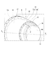
- the chamber 17 is formed of stainless steel (for example, SUS321), Inconel, or the like, and has a cylindrical inner peripheral wall portion 18 that constitutes a part of the inner peripheral portion of the cylindrical partition wall 3. That is, the inner peripheral wall portion 18 is formed in a substantially truncated cone shape in a side view reduced in diameter toward the ejection side (downstream side), and the inner diameter of the downstream end portion is the inner peripheral surface of the cylindrical partition wall 3. It is equal to the outer diameter of the upstream end.
- An outer flange portion 18 a is integrally formed on the upstream peripheral edge of the inner peripheral wall portion 18.
- the outer flange portion 18a is a member for fixing the inner peripheral wall portion 18 to the cylindrical partition wall 3, and a plurality of bolt holes (not shown) are formed at equal intervals in the circumferential direction.
- a female screw portion is formed at a position corresponding to the bolt hole of the cylindrical partition wall 3, and a bolt (not shown) is screwed into the inner peripheral wall portion 18 from the inner peripheral wall portion 18 side. It can be fastened and fixed to the cylindrical partition wall 3.
- a plurality of air intake ports 19 are formed at equal intervals in the circumferential direction so as to avoid unillustrated bolt holes.
- the air intake 19 is connected to the flow path 5 on the upstream side of the combustor 12 via a supply path 20 provided in the cylindrical partition wall 3.
- One end of the supply path 20 is connected to the air intake port 19 of the outer flange portion 18a through a joint (not shown). Thereby, a part of the air A compressed by the fan unit 11 or the compressor 4 is taken into the chamber 17.
- a valve 21 is provided in the supply path 20.
- a Teflon (registered trademark) tube or the like is used as the supply path 20.
- the outer flange 62 is integrally formed on the downstream peripheral edge of the inner peripheral wall 18.
- a plurality of through holes 65 are formed in the outer flange portion 62 at equal intervals in the circumferential direction, and the micro jet nozzle 63 is inserted into each of the through holes 65.
- a cylindrical outer peripheral wall portion 22 is provided on the outer peripheral side of the inner peripheral wall portion 18 so as to cover the inner peripheral wall portion 18 across the two outer flange portions 18 a and 62.
- the outer peripheral wall portion 22 is formed in a substantially truncated cone shape in a side view along the extending direction of the inner peripheral wall portion 18, and constitutes a part of the outer peripheral portion of the cylindrical partition wall 3. That is, the outer diameter of the upstream end portion of the outer peripheral surface of the outer peripheral wall portion 22 is equal to the outer diameter of the downstream end portion of the outer peripheral surface of the cylindrical partition wall 3 (see FIG. 1).
- the upstream peripheral portion of the outer peripheral wall portion 22 is fixed to the outer flange portion 18 a of the inner peripheral wall portion 18 by welding or the like, and the downstream peripheral portion of the outer peripheral wall portion 22 is the outer flange portion 62 of the inner peripheral wall portion 18. It is fixed by welding or the like. A part of the air A compressed by the fan 11a or the compressor 4 is taken into the space K surrounded by the outer peripheral wall portion 22 and the inner peripheral wall portion 18 thus fixed.
- the micro jet nozzle 63 attached to the outer flange portion 62 of the inner peripheral wall portion 18 is formed by piping.
- the micro jet nozzle 63 includes a first piping part 63a extending along the outer peripheral surface of the cylindrical partition wall 3 and along the axial direction, and an ejection side of the cylindrical partition wall 3 from the tip of the first piping part 63a. It is comprised by the 2nd piping part 63b extended diagonally toward the central axis C1 along the periphery 3A.
- the connecting portion between the first piping portion 63a and the outer flange portion 62 of the chamber 17 is secured by welding or the like. Further, the inclination angle ⁇ of the second piping part 63b is set to 30 to 45 degrees with respect to the central axis C1, and the air A taken into the chamber 17 is changed into the jet stream X discharged from the jet stream outlet 16A. It can be reliably injected.
- the ejection side periphery 3A of the cylindrical partition wall 3 is formed so as to become thinner toward the downstream side so that the second piping portion 63b can be arranged at a desired angle.
- the cylindrical partition wall 3 is gradually reduced in diameter toward the downstream.
- the micro jet nozzle 63 is provided so that the tip, that is, the tip of the second piping part 63b, extends along the ejection side periphery 3A of the cylindrical partition wall 3. Therefore, the injection port of the micro jet nozzle 63 is arranged at the throat SP of the cylindrical partition wall 3.
- a jet flow flows through the flow path 5 in the cylindrical partition wall 3 and is discharged from the jet flow discharge port 16A.
- the bypass flow Y flows through the flow path 6 between the cylindrical partition wall 3 and the casing 2 and is discharged from the bypass flow outlet 2B.
- the valve 21 is opened and a part of the air A compressed by the fan 11 a or the compressor 4 is taken into the chamber 17.
- the air A in the chamber 17 increases to a predetermined pressure, the air A is jetted toward the jet stream X through the micro jet nozzle 63.
- FIG. 5 is an explanatory diagram showing the flow of the jet stream X and the air A during microjet injection.
- the jet stream X is a region where the pressure is higher on the upstream side than the throat SP of the cylindrical partition wall 3.
- the downstream side of the throat SP is a lower pressure region than the upstream side. Therefore, since the micro jet injection is performed toward a low pressure region, a sufficient flow rate can be secured without increasing the pressure in the chamber 17 more than necessary. Then, immediately after the throat SP, that is, from the throat SP toward the downstream, the injection is performed so as to form an acute angle with respect to the axial direction.
- the Mach number in the pipe does not increase, and the pressure loss of the air A in the supply path 20 can be reduced. Furthermore, the path in which the pressure loss occurs can be substantially limited to the micro jet nozzle 63 only.
- the micro jet nozzle 63 can be formed so that the length in the axial direction is as short as possible. For this reason, the length of the micro jet nozzle 63 in which pressure loss occurs can be set as short as possible, and the pressure loss can be minimized.
- FIG. 6 shows the result of verifying the effect of reducing the pressure loss by providing the chamber 17 on the upstream side of the micro jet nozzle 63 in the noise reduction device 1 according to the present embodiment.
- the verification results shown in FIG. 6 show the total pressure loss coefficient (%) at the axial position of the flow path 5 upstream from the combustor 12 through the chamber 17 to the micro jet nozzle 63. ing.
- the horizontal axis represents the axial position
- the vertical axis represents the total pressure loss coefficient (%).
- the verification shown in FIG. 6 was performed by numerically analyzing the total pressure loss coefficient at each axial position under the following conditions.
- the total pressure loss coefficient increases rapidly at the connection position of the chamber 17 and the micro jet nozzle 63, that is, at a position where the axial position is 0.1 (m). This is thought to be because the total pressure loss increased because the microjet nozzle 63 had a smaller cross-sectional area than the chamber 17 having a larger cross-sectional area. However, since the cross-sectional area of the micro jet nozzle 63 is small, even if the total pressure loss rapidly increases as shown in FIG. 6, the increase in the total pressure loss in the micro jet nozzle 63 is only about 10% to 20%.
- the chamber 17 is not provided as shown by a broken line in FIG.
- the flow path 5 and the chamber are similar to the increase in the total pressure loss at the axial position 0.1 (m) shown in FIG.
- the total pressure loss suddenly increases from the position of the axial connection position ⁇ 0.18 (m) which is the connection position of 17.
- the total pressure loss at the outlet of the micro jet nozzle 63 is 50 (%).
- the presence of the chamber 17 is a mechanism that is indispensable for actually performing microjet injection in an aircraft engine. This is because the presence of the chamber 17 can suppress the total pressure loss according to the chamber part volume.
- the noise reduction device according to the present embodiment since the chamber 17 is provided, the loss of the extraction pressure from the engine for injecting the microjet is greatly reduced, and a large amount of extraction from the compressor is performed. Do not need.
- the chamber 17 is a space formed by the inner peripheral wall portion 18 and the outer peripheral wall portion 22 as compared with the conventional piping, and thus the heat is stretched. Will not cause damage to the piping. Therefore, stable micro jet injection is performed.
- the microjet-injected air A reaches the region where the discharged jet stream X and the bypass stream Y merge and mixes them appropriately. Thereby, the noise produced by the merge of the jet flow X and the bypass flow Y is reduced.
- the chamber 17 is provided between the micro jet nozzle 63 and the compressor 4, and the air A compressed by the fan 11 a or the compressor 4, that is, the flow path upstream of the combustor 12. 5 compressed air is once supplied into the chamber 17, and microjet injection is performed from the chamber 17 through the microjet nozzle 63. For this reason, the pressure loss by piping which has been a problem in the past can be reduced. Thereby, it becomes possible to perform microjet injection efficiently.
- the chamber 17 is provided instead of the pipe, a part of the pipe used between the fan unit 11 or the compressor 4 and the micro jet nozzle 63 can be reduced.
- micro jet nozzle 63 and the chamber 17 can suppress the risk of damage to thermal expansion as compared with the conventional piping, pressure leakage due to piping failure can be prevented. In addition, since there is no possibility that the flow path position of the air A is shifted by using the chamber 17, stable microjet injection can be performed.
- the chamber 17 is constituted by a cylindrical inner peripheral wall portion 18 constituting a part of the inner peripheral portion of the cylindrical partition wall 3 and an outer peripheral wall portion 22 formed so as to cover the inner peripheral wall portion 18.
- Part of the air A compressed by the fan 11a or the compressor 4 is taken into a space K surrounded by the peripheral wall 18 and the outer peripheral wall 22.
- the assembling operation can be completed only by fastening the outer flange portion 18a of the inner peripheral wall portion 18 to the cylindrical partition wall 3 with a bolt (not shown). For this reason, assembly workability
- the outer peripheral wall portion 22 of the chamber 17 constitutes the periphery of the cylindrical partition wall 3, the pipe flow or the like is not exposed to the outside, so that the cavity flow can be prevented and the additional noise accompanying this can be prevented. Furthermore, the nacelle resistance of the jet engine 100 can be reduced, and aerodynamic performance can be improved.
- the noise reduction apparatus with a chamber according to the present invention can efficiently perform microjet injection, prevent damage to piping, and prevent displacement of the arrangement position. Moreover, the noise reduction apparatus with a chamber according to the present invention can prevent the additional noise accompanying the vibration of the pipe and improve the assembly workability.
Landscapes
- Engineering & Computer Science (AREA)
- Chemical & Material Sciences (AREA)
- Combustion & Propulsion (AREA)
- Mechanical Engineering (AREA)
- General Engineering & Computer Science (AREA)
- Jet Pumps And Other Pumps (AREA)
- Structures Of Non-Positive Displacement Pumps (AREA)
Abstract
Description
本願は、2009年10月28日に、日本に出願された特願2009-247780号に基づき優先権を主張し、その内容をここに援用する。
圧縮機、燃焼器、およびタービンは、筒状隔壁である主ノズル内に設置され、ファンは、主ノズルの上流側に設置されている。ファンが取り入れた空気の大部分は、主ノズルの外周を覆うケーシング(エンジンナセル)との間に設けられたバイパス流路を通る。このバイパス流路を通った空気(バイパス流)は、タービンのコア流(ジェット流)の外周を囲むように排出されて、ジェット流と合流する。
この騒音を低減させるために、さまざまな技術が開示されている。
例えば、主ノズルの噴出側周縁にマイクロジェットノズルを設け、このマイクロジェットノズルからジェット流とバイパス流との合流部に向けてマイクロジェット噴射させる技術が開示されている(例えば、非特許文献1参照)。
さらに、配管の周囲にキャビティ流れが生じ流体騒音が発生、もしくは配管の振動に伴う付加騒音が発生する。
そして、配管を敷設する作業が煩わしく、組み立て工数が増大する。
これに加えて、配管を敷設した際のばらつきによってマイクロジェット本来の騒音低減効果が得られない可能性もある。
また、配管の振動に伴う付加騒音を防止できると共に、組み立て作業性を向上させることが可能な騒音低減装置を提供する。
前記流路の圧縮空気の一部を前記供給路を介して一旦前記チャンバ内に供給し、このチャンバから前記複数のマイクロジェットノズルを介し、前記圧縮空気を前記主ノズルから噴出されるジェット流に向けて噴射させることを特徴とする。
また、配管に代わってチャンバを設けるので、配管を削減できる分、ジェットエンジンの熱による配管の損傷を防止したり、配置位置のズレを防止したりできる。
さらに、チャンバの構造は簡素なものであるので、配管の敷設作業と比較して容易に組み付けることができる。このため、組み立て作業性を向上させることができる。
また、チャンバからマイクロジェットノズル先端に至る間の距離を短く設定することができるので、この分、より確実に圧縮空気の圧力損失を低減できる。このため、さらに効率よくマイクロジェット噴射させることが可能になる。
また、チャンバの構造をさらに簡素化でき、主ノズルの大型化を防止することができる。これに加え、さらに組み立て作業性を向上させることができる。
また、配管に代わってチャンバを設けるので、配管を削減できる分、ジェットエンジンの熱による配管の損傷を防止したり、配置位置のズレを防止できる。
さらに、チャンバの構造は簡素なものであるので、配管の敷設作業と比較して容易に組み付けることができる。このため、組み立て作業性を向上させることができる。
さらに、チャンバからマイクロジェットノズル先端に至る間の距離を短く設定することができるので、この分、より確実に圧縮空気の圧力損失を低減できる。このため、さらに効率よくマイクロジェット噴射させることが可能になる。
次に、この発明の実施形態を図1~図5に基づいて説明する。
図1は、本発明に係る騒音低減装置1が適用されたジェットエンジン100の概略構成を示す、模式断面図である。
図1に示すように、ジェットエンジン100は、筒状のケーシング2と、ケーシング2の噴出側周縁(後縁)2aから一部が突出して内挿される筒状隔壁3と、ケーシング2内に上流側から下流側へ中心軸線C1に沿って順次配列された、ファン11a、圧縮機4、燃焼器12、およびタービン13とを備える。また、ジェットエンジン100の、筒状隔壁3の噴出側(図1における右側)には、騒音低減装置1が設けられている。
筒状隔壁3内は、高速のジェット流Xが流れる流路5とされる。筒状隔壁3とケーシング2との間は、低速のバイパス流Yが流れる流路6とされる。
ケーシング2の上流側の開口は、空気Aを取り入れる空気取入口2Aとして機能する一方、ケーシング2の下流側の開口は、バイパス流Yを排出するバイパス流排出口2Bとして機能している。
ケーシング2内の上流側端部近傍であって筒状隔壁3の上流には、ファン11aが設置されている。ファン11aは、外部から空気Aを取り入れる。
ファン11aよりも下流側であって筒状隔壁3内には、圧縮機4が設置されている。圧縮機4は、ファン11aが取り入れた空気Aの一部を取り込んで圧縮する。
燃焼器12よりも下流側であって筒状隔壁3内には、タービン13が配置されている。
タービン13は、燃焼器12が排出する燃焼ガスによって、ファン11a、および圧縮機4を駆動する。
パイロン8は、ケーシング2、および筒状隔壁の中心軸線C1と直交する方向に延在する部材であって、ケーシング2よりも下流側に延びる突出部8Aを有している。
筒状隔壁3はジェット流Xを排出する主ノズルとして機能しており、この筒状隔壁3の外周部に騒音低減装置1が設けられている。
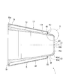
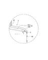
図2は、騒音低減装置1の斜視図、図3は、図2のA-A線に沿う断面図、図4は、図3のB部拡大図である。
図1~図4に示すように、騒音低減装置1は、筒状隔壁3の外周部に設けられたチャンバ17と、このチャンバ17の下流側(図1、図2における右側)であって、かつ筒状隔壁3の噴出側周縁3Aに沿って複数設けられているマイクロジェットノズル63とを有している。なお、複数のマイクロジェットノズル63は何れも同一形状であるので、図2において、マイクロジェットノズル63を1つのみ図示し、他のマイクロジェットノズル63の図示を省略する。
すなわち、内周壁部18は、噴出側(下流側)に向かうにしたがって縮径された側面視略円錐台状に形成されており、下流側端部の内径が筒状隔壁3の内周面の上流側端部の外径と等しくなっている。
内周壁部18の上流側周縁には、外フランジ部18aが一体成形されている。この外フランジ部18aは、内周壁部18を筒状隔壁3に固定するための部材で、複数のボルト孔(不図示)が周方向に等間隔に形成されている。一方、筒状隔壁3のボルト孔に対応する位置には、雌ネジ部が刻設されており、ここに内周壁部18側から不図示のボルトを螺入することによって、内周壁部18を筒状隔壁3に締結固定できる。
この空気取入口19は、筒状隔壁3に設けられている供給路20を介して燃焼器12よりも上流側の流路5に接続されている。供給路20は、この一端が不図示の継手を介して外フランジ部18aの空気取入口19に接続されている。これにより、ファン部11又は圧縮機4が圧縮した空気Aの一部がチャンバ17に取り込まれる。また、供給路20の途中には、バルブ21が設けられている。
なお、供給路20としては、例えば、テフロン(登録商標)チューブ等が用いられる。
テフロン(登録商標)チューブを用いることにより、エンジンの熱伸びによる管の破損を防げるほか、管摩擦損失を低減し、効率よく噴射することが可能になる。
外周壁部22の上流側周縁部は、内周壁部18の外フランジ部18aに溶接等により固定されていると共に、外周壁部22の下流側周縁部は、内周壁部18の外フランジ部62に溶接等により固定されている。このように固定された外周壁部22と内周壁部18とで取り囲まれる空間Kに、ファン11a又は圧縮機4で圧縮した空気Aの一部が取り込まれる。
また、第二配管部63bの傾斜角度θは中心軸線C1に対し、30~45度に設定されており、チャンバ17に取り込まれた空気Aをジェット流排出口16Aから排出されるジェット流Xに確実に噴射させることができる。ここで、筒状隔壁3の噴出側周縁3Aは、第二配管部63bを所望の角度に配置可能に、下流に向かうに従って薄肉となるように形成されている。
次に、ジェットエンジン100、および騒音低減装置1の作用について説明する。
図1に示すように、航空機の離陸時には、まず、ファン11aを回転させて空気取入口2Aから空気Aを取り入れる。この空気Aの一部は、圧縮機4により圧縮され、燃焼器12にて燃料と混合されて燃焼される。
タービン13では、燃焼器12から排出された燃焼ガスによってファン11a、および圧縮機4の駆動力が発生する。以降は、タービン13によって発生した駆動力によって、ファン11aが回転して空気Aが取り込まれていく。
このとき、バルブ21を開いてファン11a又は圧縮機4で圧縮された空気Aの一部をチャンバ17内に取り込む。そして、チャンバ17内の空気Aが所定の圧力まで高まると、この空気Aがマイクロジェットノズル63を介してジェット流Xに向かって噴射される。
図5において、ジェット流Xは、筒状隔壁3のスロートSPよりも上流側が圧力の高い領域となる。一方、スロートSPよりも下流側が上流側と比較して圧力の低い領域となる。したがって、マイクロジェット噴射は、圧力の低い領域に向けて噴射される事になるので、チャンバ17内の圧力を必要以上に高めることなく、十分な流量を確保できる。そして、スロートSPの直後、つまり、スロートSPから下流に向かって、軸方向に対して鋭角をなすように噴射が行われる。
図6に示す検証は、以下の条件を用い、各々の軸方向位置における全圧損失係数を数値解析することで行なった。
流路5の内径:Φ5mm、32本
マイクロジェット出口面積:噴射管内径Φ3.15(mm)×sqrt(32本/20本)=Φ3.52mm
ここで、図6に破線で示すようにチャンバ17が設けられていない場合、図6に示す軸方向位置0.1(m)の位置における全圧損失の増加と同様に、流路5とチャンバ17の接続位置である軸方向位置―0.18(m)の位置から全圧損失が急激に増加する。軸方向位置―0.18(m)の位置から、軸方向位置0.1(m)の位置と同様に全圧損失が増加すると、マイクロジェットノズル63の出口における全圧損失は50(%)を超えることが明らかである。
このように、本実施の形態に係る騒音低減装置においては、チャンバ17が備えられているため、マイクロジェットを噴射するためのエンジンからの抽気圧力の損失を大きく低減させ、コンプレッサからの多大な抽気を必要としない。
マイクロジェット噴射された空気Aは、排出されたジェット流Xとバイパス流Yとが合流する領域に到達して両者を好適に混合させる。これにより、ジェット流Xとバイパス流Yとの合流によって生じる騒音が低減される。
上述の実施形態によれば、マイクロジェットノズル63と圧縮機4との間にチャンバ17を設け、ファン11a又は圧縮機4で圧縮された空気A、つまり、燃焼器12よりも上流側の流路5の圧縮空気を一旦チャンバ17内に供給し、このチャンバ17からマイクロジェットノズル63を介してマイクロジェット噴射を行っている。このため、従来問題となっていた配管による圧力損失を低減することができる。これにより、効率よくマイクロジェット噴射させることが可能になる。
また、配管に代わってチャンバ17を設けるので、ファン部11又は圧縮機4からマイクロジェットノズル63に至る間に用いられる配管の一部を削減できる。マイクロジェットノズル63やチャンバ17は、従来の配管と比較して熱膨張に対する破損リスクを小さく抑えることができるので、配管破損による圧力漏れを防止することができる。これに加え、チャンバ17を用いることで空気Aの流路位置がずれる可能性がないので、安定したマイクロジェット噴射を行うことができる。
これに加え、内周壁部18の外フランジ部18aを筒状隔壁3に不図示のボルトにより締結固定するだけで組み付け作業を完了させることができる。このため、従来のような配管の敷設作業と比較して組み立て作業性を向上させることができる。
また、本発明に係るチャンバ付騒音低減装置は、配管の振動に伴う付加騒音を防止できると共に、組み立て作業性を向上させることが可能である。
2 ケーシング
3 筒状隔壁(主ノズル)
4 圧縮機
5 流路
12 燃焼器
17 チャンバ
18 内周壁部
18a,62 外フランジ部
20 供給路
22 外周壁部
63 マイクロジェットノズル
63a 第一配管部
63b 第二配管部
100 ジェットエンジン
A 空気
K 空間
X ジェット流
Claims (3)
- ジェットエンジン内の燃焼器より上流側の流路と、前記ジェットエンジンの主ノズルの噴出側周縁に設けられた複数のマイクロジェットノズルとを接続する供給路の途中にチャンバを設け、
前記流路の圧縮空気の一部を前記供給路を介して一旦前記チャンバ内に供給し、このチャンバから前記複数のマイクロジェットノズルを介し、前記圧縮空気を前記主ノズルから噴出されるジェット流に向けて噴射させるチャンバ付騒音低減装置。 - 前記主ノズルの外周面であって、かつ前記マイクロジェットノズルの近傍に、前記チャンバを設けた請求項1に記載のチャンバ付騒音低減装置。
- 前記チャンバは、
前記主ノズルの内周部の一部を構成する内周壁部と、
前記主ノズルの外周部の一部を構成し、かつ前記内周壁部を覆うように形成された外周壁部とを有し、
これら内周壁部と外周壁部との間に形成された空間に、前記圧縮空気を取り込むように構成されている請求項2に記載のチャンバ付騒音低減装置。
Priority Applications (5)
| Application Number | Priority Date | Filing Date | Title |
|---|---|---|---|
| CA2779149A CA2779149C (en) | 2009-10-28 | 2010-10-27 | Noise reduction system with chamber |
| JP2011538456A JP5472313B2 (ja) | 2009-10-28 | 2010-10-27 | チャンバ付騒音低減装置 |
| US13/504,200 US8813907B2 (en) | 2009-10-28 | 2010-10-27 | Noise reduction system with chamber |
| CN201080048438.7A CN102575616B (zh) | 2009-10-28 | 2010-10-27 | 带有腔室的噪声降低装置 |
| EP10826774.1A EP2495424B1 (en) | 2009-10-28 | 2010-10-27 | Jet engine comprising a noise reduction device with chamber |
Applications Claiming Priority (2)
| Application Number | Priority Date | Filing Date | Title |
|---|---|---|---|
| JP2009-247780 | 2009-10-28 | ||
| JP2009247780 | 2009-10-28 |
Publications (1)
| Publication Number | Publication Date |
|---|---|
| WO2011052642A1 true WO2011052642A1 (ja) | 2011-05-05 |
Family
ID=43922067
Family Applications (1)
| Application Number | Title | Priority Date | Filing Date |
|---|---|---|---|
| PCT/JP2010/069079 Ceased WO2011052642A1 (ja) | 2009-10-28 | 2010-10-27 | チャンバ付騒音低減装置 |
Country Status (6)
| Country | Link |
|---|---|
| US (2) | US9528468B2 (ja) |
| EP (1) | EP2495424B1 (ja) |
| JP (1) | JP5472313B2 (ja) |
| CN (1) | CN102575616B (ja) |
| CA (1) | CA2779149C (ja) |
| WO (1) | WO2011052642A1 (ja) |
Families Citing this family (17)
| Publication number | Priority date | Publication date | Assignee | Title |
|---|---|---|---|---|
| US9528468B2 (en) * | 2009-10-28 | 2016-12-27 | Ihi Corporation | Noise reduction system |
| FR3009027B1 (fr) * | 2013-07-26 | 2018-04-06 | Airbus Operations | Ensemble turbomachine d'aeronef a bruit de jet attenue. |
| FR3028294B1 (fr) * | 2014-11-06 | 2020-06-12 | Safran Aircraft Engines | Carenage pour melangeur de tuyere de turbomachine a double flux |
| RU2731780C2 (ru) * | 2015-03-26 | 2020-09-08 | Сафран Эркрафт Энджинз | Устройство с решетками для выталкивания микроструй для уменьшения шума реактивной струи газотурбинного двигателя |
| US10267160B2 (en) | 2015-08-27 | 2019-04-23 | Rolls-Royce North American Technologies Inc. | Methods of creating fluidic barriers in turbine engines |
| US10233869B2 (en) | 2015-08-27 | 2019-03-19 | Rolls Royce North American Technologies Inc. | System and method for creating a fluidic barrier from the leading edge of a fan blade |
| US10718221B2 (en) | 2015-08-27 | 2020-07-21 | Rolls Royce North American Technologies Inc. | Morphing vane |
| US9976514B2 (en) | 2015-08-27 | 2018-05-22 | Rolls-Royce North American Technologies, Inc. | Propulsive force vectoring |
| US10125622B2 (en) | 2015-08-27 | 2018-11-13 | Rolls-Royce North American Technologies Inc. | Splayed inlet guide vanes |
| US9915149B2 (en) | 2015-08-27 | 2018-03-13 | Rolls-Royce North American Technologies Inc. | System and method for a fluidic barrier on the low pressure side of a fan blade |
| US10280872B2 (en) | 2015-08-27 | 2019-05-07 | Rolls-Royce North American Technologies Inc. | System and method for a fluidic barrier from the upstream splitter |
| US10267159B2 (en) | 2015-08-27 | 2019-04-23 | Rolls-Royce North America Technologies Inc. | System and method for creating a fluidic barrier with vortices from the upstream splitter |
| US20170057649A1 (en) | 2015-08-27 | 2017-03-02 | Edward C. Rice | Integrated aircraft propulsion system |
| GB201701710D0 (en) * | 2017-02-02 | 2017-03-22 | Rolls Royce Plc | Core cowl after-body |
| US11365704B2 (en) * | 2018-02-27 | 2022-06-21 | New York University In Abu Dhabi Corportion | Directionally targeted jet noise reduction system and method |
| CN113309585B (zh) * | 2021-05-27 | 2022-08-26 | 中国航发南方工业有限公司 | 排气结构及发动机 |
| WO2025019669A1 (en) * | 2023-07-19 | 2025-01-23 | University Of Cincinnati | Nozzle with sweeping jet actuator and associated methods |
Citations (7)
| Publication number | Priority date | Publication date | Assignee | Title |
|---|---|---|---|---|
| GB1141784A (en) * | 1967-01-18 | 1969-01-29 | Snecma | Nozzles capable of having a silencing effect |
| JPS4723605B1 (ja) * | 1967-04-27 | 1972-07-01 | ||
| US20040088967A1 (en) * | 2002-11-09 | 2004-05-13 | Webster John R. | Suppression of part of the noise from a gas turbine engine |
| JP2005195019A (ja) | 2003-12-30 | 2005-07-21 | General Electric Co <Ge> | 振動ジェットを使用してジェットエンジン排気騒音を低減するための装置 |
| US20050210860A1 (en) * | 2004-03-26 | 2005-09-29 | Gutmark Ephraim J | Methods and apparatus for operating gas turbine engines |
| JP2009247780A (ja) | 2008-04-10 | 2009-10-29 | Sammy Corp | 弾球遊技機 |
| JP2010518323A (ja) | 2007-02-14 | 2010-05-27 | ザ・ボーイング・カンパニー | ジェットエンジンの排気騒音を削減するシステム及び方法 |
Family Cites Families (22)
| Publication number | Priority date | Publication date | Assignee | Title |
|---|---|---|---|---|
| US3216653A (en) * | 1962-07-09 | 1965-11-09 | Bertin & Cie | Ejectors and piping systems operating with a divergent fluid wall |
| US2826895A (en) * | 1953-09-03 | 1958-03-18 | Fairchild Engine & Airplane | Bearing cooling system |
| US2990905A (en) | 1957-05-13 | 1961-07-04 | Lilley Geoffrey Michael | Jet noise suppression means |
| US2998700A (en) * | 1959-04-29 | 1961-09-05 | Jr Harvey R Chaplin | Jet diffuser for shrouded propellers |
| US6457654B1 (en) * | 1995-06-12 | 2002-10-01 | Georgia Tech Research Corporation | Micromachined synthetic jet actuators and applications thereof |
| US7159383B2 (en) * | 2000-10-02 | 2007-01-09 | Rohr, Inc. | Apparatus, method and system for gas turbine engine noise reduction |
| DE60329905D1 (de) * | 2002-02-22 | 2009-12-17 | Nordam Group Inc | Doppelmischer-abgasdüse |
| US7293401B2 (en) * | 2002-03-20 | 2007-11-13 | The Regents Of The University Of California | Jet engine noise suppressor |
| US7234304B2 (en) * | 2002-10-23 | 2007-06-26 | Pratt & Whitney Canada Corp | Aerodynamic trip to improve acoustic transmission loss and reduce noise level for gas turbine engine |
| US7246481B2 (en) | 2004-03-26 | 2007-07-24 | General Electric Company | Methods and apparatus for operating gas turbine engines |
| GB0505246D0 (en) * | 2005-03-15 | 2005-04-20 | Rolls Royce Plc | Engine noise |
| FR2904663B1 (fr) * | 2006-08-01 | 2012-02-03 | Snecma | Turbomachine a double flux a variation artificielle de sa section de col |
| US8015819B2 (en) * | 2006-09-29 | 2011-09-13 | The United States Of America As Represented By The Administrator Of The National Aeronautics And Space Administration | Wet active chevron nozzle for controllable jet noise reduction |
| US8904795B2 (en) * | 2008-02-25 | 2014-12-09 | Ihi Corporation | Noise reducing device and jet propulsion system |
| FR2929335B1 (fr) * | 2008-03-31 | 2012-06-01 | Airbus France | Dispositif de reduction du bruit genere par un reacteur d'aeronef a jets de fluide de meme orientation |
| FR2929337B1 (fr) * | 2008-03-31 | 2012-06-01 | Airbus France | Dispositif a jets secondaires de reduction du bruit genere par un reacteur d'aeronef |
| FR2929336B1 (fr) * | 2008-03-31 | 2012-06-01 | Airbus France | Dispositif a jets plans de reduction du bruit genere par un reacteur d'aeronef |
| FR2929334B1 (fr) * | 2008-03-31 | 2012-06-01 | Airbus France | Dispositif de reduction du bruit genere par reacteur d'aeronef a conduits de fluide coudes |
| US9528468B2 (en) * | 2009-10-28 | 2016-12-27 | Ihi Corporation | Noise reduction system |
| JP5446749B2 (ja) * | 2009-11-09 | 2014-03-19 | 株式会社Ihi | エンジン排気ノズル及び航空機エンジン |
| JP5446783B2 (ja) * | 2009-11-27 | 2014-03-19 | 株式会社Ihi | エンジン排気ノズル及び航空機エンジン |
| FR2970744A1 (fr) * | 2011-01-24 | 2012-07-27 | Airbus Operations Sas | Reacteur d'aeronef comprenant un systeme de reduction du bruit genere par l'ejection des gaz |
-
2010
- 2010-10-26 US US13/504,195 patent/US9528468B2/en active Active
- 2010-10-27 WO PCT/JP2010/069079 patent/WO2011052642A1/ja not_active Ceased
- 2010-10-27 EP EP10826774.1A patent/EP2495424B1/en active Active
- 2010-10-27 CN CN201080048438.7A patent/CN102575616B/zh not_active Expired - Fee Related
- 2010-10-27 JP JP2011538456A patent/JP5472313B2/ja active Active
- 2010-10-27 US US13/504,200 patent/US8813907B2/en active Active
- 2010-10-27 CA CA2779149A patent/CA2779149C/en active Active
Patent Citations (7)
| Publication number | Priority date | Publication date | Assignee | Title |
|---|---|---|---|---|
| GB1141784A (en) * | 1967-01-18 | 1969-01-29 | Snecma | Nozzles capable of having a silencing effect |
| JPS4723605B1 (ja) * | 1967-04-27 | 1972-07-01 | ||
| US20040088967A1 (en) * | 2002-11-09 | 2004-05-13 | Webster John R. | Suppression of part of the noise from a gas turbine engine |
| JP2005195019A (ja) | 2003-12-30 | 2005-07-21 | General Electric Co <Ge> | 振動ジェットを使用してジェットエンジン排気騒音を低減するための装置 |
| US20050210860A1 (en) * | 2004-03-26 | 2005-09-29 | Gutmark Ephraim J | Methods and apparatus for operating gas turbine engines |
| JP2010518323A (ja) | 2007-02-14 | 2010-05-27 | ザ・ボーイング・カンパニー | ジェットエンジンの排気騒音を削減するシステム及び方法 |
| JP2009247780A (ja) | 2008-04-10 | 2009-10-29 | Sammy Corp | 弾球遊技機 |
Non-Patent Citations (2)
| Title |
|---|
| BRENTON GRESKA, THE EFFECTS OF MICROJET INJECTION ON AN F404 JET ENGINE, AIAA2005-3047, 11TH AIAA/CEAS AEROACOUSTICS CONFERENCE (26TH AIAAAEROACOUSTICS CONFERENCE, 23 May 2005 (2005-05-23) |
| See also references of EP2495424A4 |
Also Published As
| Publication number | Publication date |
|---|---|
| CA2779149A1 (en) | 2011-05-05 |
| US9528468B2 (en) | 2016-12-27 |
| EP2495424A4 (en) | 2015-04-22 |
| CN102575616B (zh) | 2015-02-25 |
| JP5472313B2 (ja) | 2014-04-16 |
| CN102575616A (zh) | 2012-07-11 |
| US20120240587A1 (en) | 2012-09-27 |
| US20120228054A1 (en) | 2012-09-13 |
| CA2779149C (en) | 2014-11-18 |
| EP2495424B1 (en) | 2019-03-13 |
| EP2495424A1 (en) | 2012-09-05 |
| JPWO2011052642A1 (ja) | 2013-03-21 |
| US8813907B2 (en) | 2014-08-26 |
Similar Documents
| Publication | Publication Date | Title |
|---|---|---|
| JP5472313B2 (ja) | チャンバ付騒音低減装置 | |
| JP4862961B2 (ja) | 騒音低減装置及びジェット推進システム | |
| JP5342130B2 (ja) | ターボファンエンジンカウルアセンブリ及び内部コアカウルバッフルアセンブリ | |
| CN105626310B (zh) | 燃气涡轮发动机及组装其的方法 | |
| JP4890423B2 (ja) | ターボファンエンジンノズル組立体及びターボファンエンジン組立体 | |
| CN108626747A (zh) | 燃烧器声阻尼结构 | |
| CN102037232B (zh) | 降低航空器喷气发动机噪音的带有弯曲流体管道的装置 | |
| CN102037231B (zh) | 降低航空器喷气发动机产生的噪音的带有次级射流的装置 | |
| CN106481455A (zh) | 用于抑制在燃气涡轮燃烧器内的噪声的系统 | |
| CN101443543A (zh) | 配备有用于减弱由涡轮喷气发动机产生的噪声的装置的涡轮喷气发动机短舱 | |
| JP6005629B2 (ja) | 航空機推進エンジンのジェットによる騒音を低減するための装置 | |
| JP5459317B2 (ja) | 騒音低減装置 | |
| JP2007093200A (ja) | コーキング防止型インジェクタアーム | |
| US20150219013A1 (en) | Aircraft turbomachine assembly with reduced jet noise | |
| JP2017190777A (ja) | ガスタービン用組込み式入口サイレンサおよび抽気加熱システム | |
| WO2024176914A1 (ja) | 燃焼器用筒体、燃焼器及びガスタービン | |
| US7685805B2 (en) | Turbofan gas turbine engine and nacelle arrangement | |
| EP3121430B1 (en) | A nacelle assembly |
Legal Events
| Date | Code | Title | Description |
|---|---|---|---|
| WWE | Wipo information: entry into national phase |
Ref document number: 201080048438.7 Country of ref document: CN |
|
| 121 | Ep: the epo has been informed by wipo that ep was designated in this application |
Ref document number: 10826774 Country of ref document: EP Kind code of ref document: A1 |
|
| WWE | Wipo information: entry into national phase |
Ref document number: 2011538456 Country of ref document: JP Ref document number: 2779149 Country of ref document: CA |
|
| NENP | Non-entry into the national phase |
Ref country code: DE |
|
| WWE | Wipo information: entry into national phase |
Ref document number: 2010826774 Country of ref document: EP |
|
| WWE | Wipo information: entry into national phase |
Ref document number: 13504200 Country of ref document: US |