WO2011052682A1 - 難削鋳鉄の加工方法 - Google Patents
難削鋳鉄の加工方法 Download PDFInfo
- Publication number
- WO2011052682A1 WO2011052682A1 PCT/JP2010/069172 JP2010069172W WO2011052682A1 WO 2011052682 A1 WO2011052682 A1 WO 2011052682A1 JP 2010069172 W JP2010069172 W JP 2010069172W WO 2011052682 A1 WO2011052682 A1 WO 2011052682A1
- Authority
- WO
- WIPO (PCT)
- Prior art keywords
- cutting
- cutting tip
- workpiece
- cast iron
- difficult
- Prior art date
- Legal status (The legal status is an assumption and is not a legal conclusion. Google has not performed a legal analysis and makes no representation as to the accuracy of the status listed.)
- Ceased
Links
Images

Classifications
-
- B—PERFORMING OPERATIONS; TRANSPORTING
- B23—MACHINE TOOLS; METAL-WORKING NOT OTHERWISE PROVIDED FOR
- B23C—MILLING
- B23C3/00—Milling particular work; Special milling operations; Machines therefor
- B23C3/02—Milling surfaces of revolution
-
- B—PERFORMING OPERATIONS; TRANSPORTING
- B23—MACHINE TOOLS; METAL-WORKING NOT OTHERWISE PROVIDED FOR
- B23C—MILLING
- B23C5/00—Milling-cutters
- B23C5/16—Milling-cutters characterised by physical features other than shape
- B23C5/20—Milling-cutters characterised by physical features other than shape with removable cutter bits or teeth or cutting inserts
-
- B—PERFORMING OPERATIONS; TRANSPORTING
- B23—MACHINE TOOLS; METAL-WORKING NOT OTHERWISE PROVIDED FOR
- B23C—MILLING
- B23C2222/00—Materials of tools or workpieces composed of metals, alloys or metal matrices
- B23C2222/14—Cast iron
-
- B—PERFORMING OPERATIONS; TRANSPORTING
- B23—MACHINE TOOLS; METAL-WORKING NOT OTHERWISE PROVIDED FOR
- B23C—MILLING
- B23C2226/00—Materials of tools or workpieces not comprising a metal
- B23C2226/12—Boron nitride
- B23C2226/125—Boron nitride cubic [CBN]
-
- Y—GENERAL TAGGING OF NEW TECHNOLOGICAL DEVELOPMENTS; GENERAL TAGGING OF CROSS-SECTIONAL TECHNOLOGIES SPANNING OVER SEVERAL SECTIONS OF THE IPC; TECHNICAL SUBJECTS COVERED BY FORMER USPC CROSS-REFERENCE ART COLLECTIONS [XRACs] AND DIGESTS
- Y10—TECHNICAL SUBJECTS COVERED BY FORMER USPC
- Y10T—TECHNICAL SUBJECTS COVERED BY FORMER US CLASSIFICATION
- Y10T407/00—Cutters, for shaping
- Y10T407/26—Cutters, for shaping comprising cutting edge bonded to tool shank
-
- Y—GENERAL TAGGING OF NEW TECHNOLOGICAL DEVELOPMENTS; GENERAL TAGGING OF CROSS-SECTIONAL TECHNOLOGIES SPANNING OVER SEVERAL SECTIONS OF THE IPC; TECHNICAL SUBJECTS COVERED BY FORMER USPC CROSS-REFERENCE ART COLLECTIONS [XRACs] AND DIGESTS
- Y10—TECHNICAL SUBJECTS COVERED BY FORMER USPC
- Y10T—TECHNICAL SUBJECTS COVERED BY FORMER US CLASSIFICATION
- Y10T409/00—Gear cutting, milling, or planing
- Y10T409/30—Milling
- Y10T409/303752—Process
- Y10T409/303808—Process including infeeding
Definitions
- the present invention relates to a method for processing difficult-to-cut cast iron, and more specifically, in cutting of hard-to-cut cast iron using a cutting tip containing CBN (Cubic Boron Nitride),
- the present invention relates to a method for processing difficult-to-cut cast iron that can achieve both improvement in cutting speed.
- the cutting speed V can be reduced by using a cutting tip made of a so-called high content CBN sintered body having a CBN content of 85% by volume or more. 1000 m / min.
- the above high-speed continuous machining has been put into practical use in part.
- the cutting edge temperature of the cutting tip is likely to rise during the cutting process, and the cutting is made of a CBN sintered body having a high content and a high CBN content that has high reactivity with iron.
- the wear of the cutting tip proceeds remarkably fast.
- a cutting tip made of a CBN sintered body having a high content ratio in the cutting of difficult-to-cut cast iron.
- ceramics such as TiC (titanium carbide), Al 2 O 3 (alumina), Si 3 N 4 (silicon nitride), and SiAlON (sialon) are used for cutting difficult-to-cut cast iron.
- a cutting tip made of a sintered body or a CBN sintered body (so-called low-content CBN sintered body) obtained by mixing these ceramic powders and CBN particles and sintering them at a high pressure is employed.
- the cutting speed is 400 m / min.
- the current situation is as follows.
- an object of the present invention is to provide a method for machining difficult-to-cut cast iron capable of achieving both a longer life of a cutting tip and an improvement in machining efficiency in cutting of difficult-to-cut cast iron.
- the processing method of difficult-to-cut cast iron includes a step of preparing a workpiece made of difficult-to-cut cast iron and a step of cutting the workpiece using a cutting tool having a cutting tip.
- the cutting tip is intermittently brought into contact with the workpiece by revolving while the cutting tool rotates.
- the cutting tip is made of a sintered body having a CBN content of 85% by volume or more.
- the thermal conductivity of the cutting tip is 100 W / (m ⁇ K) or more.
- the present inventor has conducted detailed studies on measures for achieving both a longer life of a cutting tip and an improvement in machining efficiency in cutting of difficult-to-cut cast iron.
- the cutting speed V is set to 100 m / min. Based on the knowledge that the wear speed of the cutting tip is significantly reduced even when machining difficult-to-cut cast iron when set to the following low speeds, the use of a cutting tip made of a CBN sintered body with high thermal conductivity, and the cutting tool The present inventors have found that the wear rate of the cutting tip can be significantly reduced by combining with the contouring process in which the cutting tip comes into intermittent contact with the workpiece by revolving while rotating.
- contouring is employed in which the cutting tip intermittently contacts the workpiece by revolving while the cutting tool rotates. For this reason, the cutting tip repeats the state of contacting the workpiece and the state of idling without contacting. As a result, since the cutting tip heated at the time of contact with the workpiece is cooled during idling, the temperature rise of the cutting tip during processing is suppressed.
- the thermal conductivity of the cutting tip is set to a high value of 100 W / (m ⁇ K) or more, heat dissipation from the cutting tip proceeds efficiently, The temperature rise of the cutting tip is further suppressed. As a result, even if the cutting tip is cooled before the temperature rises beyond the limit and a high cutting speed is adopted, the progress of significant wear caused by the reaction with iron in the cutting tip made of a CBN sintered body is avoided.
- the contouring process is adopted as described above, the impact is repeatedly applied to the cutting tip by intermittent cutting.
- the cutting tip which consists of a sintered compact whose CBN content rate is 85 volume% or more is employ
- the CBN content of the sintered body constituting the cutting tip is less than 85% by volume, the material strength is insufficient with respect to repeated impact described above, Damage such as defects may occur. Therefore, in the present invention, the CBN content is set to 85% by volume or more. Further, in the method for processing difficult-to-cut cast iron according to the present invention, if the thermal conductivity of the cutting tip is less than 100 W / (m ⁇ K), the heat radiation effect of the cutting heat generated during cutting is reduced. As a result, the temperature range of the thermal history is increased, which may cause thermal cracks at the cutting edge and shorten the life until failure. Therefore, in the present invention, the thermal conductivity of the cutting tip is set to 100 W / (m ⁇ K) or more.
- the contact time which is the time in which the cutting tip and the workpiece are in contact
- the cutting tip is separated from the workpiece.
- the idling time which is the idling time in this state, is Y
- X is 0.2 ⁇ sec (microseconds) to 2 ⁇ sec
- X / Y is 0.06 to 0.16.
- the cutting speed V is set to 100 m / min.
- the wear speed of the cutting tip is greatly reduced in cutting of difficult-to-cut cast iron.
- the cutting speed V is set to 20 m / min.
- X is set to 0.2 ⁇ sec or more and 2 ⁇ sec or less
- X / Y is set to 0.06 or more and 0.16 or less, thereby significantly reducing the wear rate of the cutting tip. It became clear that high-efficiency machining could be realized.
- contact time means the time during which the cutting tip is in contact with the workpiece while the cutting tool rotates once.
- the “idling time” means a time during which the cutting tip and the workpiece are separated during the rotation of the cutting tool once (a time when the cutting tool is not in contact).
- the thermal conductivity of the cutting tip is 120 W / (m ⁇ K) or more, and the cutting speed in the step of cutting the workpiece is 1000 m / min. That's it.
- the thermal conductivity of the cutting tip By setting the thermal conductivity of the cutting tip to 120 W / (m ⁇ K) or more, 1000 m / min. Even when the above cutting speed is adopted, it is possible to sufficiently suppress the wear of the cutting tip.
- the average particle size of the CBN particles constituting the cutting tip is preferably 3 ⁇ m or more.
- the thermal conductivity of the cutting tip can be easily improved.
- a workpiece made of difficult-to-cut cast iron is prepared. Specifically, for example, as shown in FIG. 1, a workpiece 20 made of hard-to-cut cast iron such as FCD material, FCV material, CGI material, ADI material, etc. and having a cylindrical prepared hole 21 is prepared. . Then, the cutting tool 10 with the cutting tip 11 attached to the tip is inserted into the pilot hole 21 and the wall surface of the pilot hole 21 is cut.
- the cutting tool 10 rotates around the axis ⁇ , that is, along the arrow A, and around the axis ⁇ that coincides with the central axis of the pilot hole 21, that is, along the arrow B. Revolve. Thereby, the cutting tip 11 contacts the wall surface of the pilot hole 21 intermittently, and cuts the said wall surface. That is, the workpiece 20 is contoured by the tool 10.
- the cutting tip 11 is made of a sintered body having a CBN content of 85% by volume or more. Furthermore, the thermal conductivity of the cutting tip 11 is 100 W / (m ⁇ K) or more.
- the cutting tool 10 revolves while rotating, so that the cutting tip 11 intermittently contacts the wall surface of the prepared hole 21 formed in the workpiece 20. Is implemented. Therefore, the cutting tip 11 repeats the contact state and the idling state with respect to the workpiece 20. As a result, since the cutting tip 11 heated at the time of contact with the workpiece 20 is cooled during idling, the temperature rise of the cutting tip 11 at the time of processing is suppressed. Further, in the drilling of the present embodiment, since the thermal conductivity of the cutting tip 11 is 100 W / (m ⁇ K) or more, the heat dissipation from the cutting tip 11 proceeds efficiently, and the cutting tip at the time of machining is processed. 11 is further suppressed. As a result, even when the temperature of the cutting tip 11 is cooled before rising beyond the limit and a high cutting speed is adopted, the progress of significant wear caused by the reaction with iron in the cutting tip 11 made of a CBN sintered body. Avoided.
- the contouring process since the contouring process is adopted, the impact is repeatedly applied to the cutting tip 11 by intermittent cutting.
- the sintered body having a CBN content of 85% by volume or more is used.
- X is 0.2 ⁇ sec or more and 2 ⁇ sec or less
- X / Y is 0.8. It is preferable to set it as 06-0.16. Thereby, high-efficiency machining can be realized while significantly reducing the wear rate of the cutting tip 11.
- the thermal conductivity of the cutting tip 11 is 120 W / (m ⁇ K) or more, and the cutting speed is 1000 m / min.
- the above is preferable.
- the thermal conductivity of the cutting tip 11 is 120 W / (m ⁇ K) or more, 1000 m / min. Even when the above cutting speeds are employed, the wear of the cutting tip 11 is sufficiently suppressed, and high processing efficiency is achieved.
- the average particle size of the CBN particles constituting the cutting tip 11 is 3 ⁇ m or more. Thereby, the thermal conductivity of the cutting tip 11 can be improved easily.
- the improvement of the thermal conductivity of the cutting tip 11 can be achieved, for example, by increasing the particle size of the CBN particles constituting the cutting tip 11 and adjusting the composition of the cutting tip 11.
- the content of CBN particles is preferably 90% by volume or more.
- the particle size of CBN is preferably set to 20 ⁇ m or less, and the improvement of the thermal conductivity of the cutting tip 11 is achieved by increasing the content of CBN particles that can simultaneously improve the strength and the thermal conductivity. It is preferable.
- Example 1 Example 1 will be described below.
- a machining method that affects the wear amount of a cutting tip by performing contouring inner diameter machining and continuous inner diameter machining on a workpiece made of FCD450, which is difficult-to-cut cast iron, using a cutting tip made of a CBN sintered body An experiment was conducted to investigate the influence of the CBN content of the cutting tip and the thermal conductivity of the cutting tip.
- Table 1 shows the processing conditions for contouring inner diameter processing
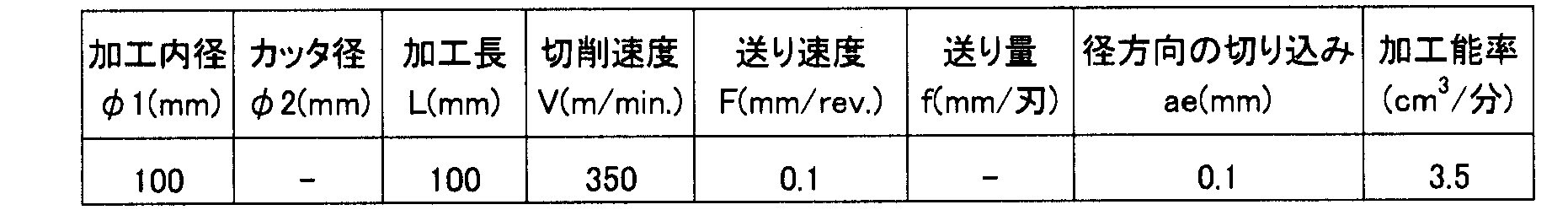
- Table 2 shows the processing conditions for continuous inner diameter processing.
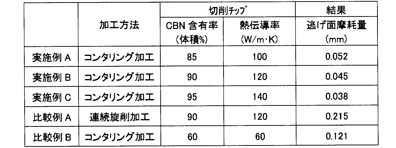
- Table 3 shows the CBN content and thermal conductivity of the cutting tip, and the amount of flank wear of the cutting tip when the volume of chips removed from the workpiece by cutting is 50 cm 3 .
- the cutting tip was model number CNGA120408.
- the binder constituting the CBN sintered bodies of Examples A to C and Comparative Example A contains at least WC, Co compound and Al compound.
- the binder of the CBN sintered body of Comparative Example B contains at least a Ti compound and an Al compound.
- Example B of the present invention that employs the same cutting tip is compared with Comparative Example A that is outside the scope of the present invention, Example B despite the same processing efficiency.
- the flank wear amount is significantly smaller than the flank wear amount of Comparative Example A. This is because in Example B employing contouring, the contact time of the cutting edge of the cutting tip to the workpiece is as short as several microseconds or less, and cooling is performed by idling before the temperature of the cutting edge rises beyond the limit. Therefore, it is presumed that the wear was suppressed as compared with Comparative Example A in which the cutting edge continuously contacts. From this result, it is confirmed that the wear rate of the cutting tip can be significantly reduced by adopting the contouring process for cutting difficult-to-cut cast iron using the cutting tip made of a CBN sintered body.
- the CBN content of the cutting tip is set to 85% by volume or more, It is confirmed that the wear of the cutting tip can be sufficiently suppressed by setting the conductivity to 100 W / (m ⁇ K) or more.
- Example 2 By using a cutting tip made of a CBN sintered body and performing contouring inner diameter machining on a workpiece made of FC250, which is difficult-to-cut cast iron, the amount of CBN that affects the amount of wear of the cutting tip and the occurrence of thermal cracks
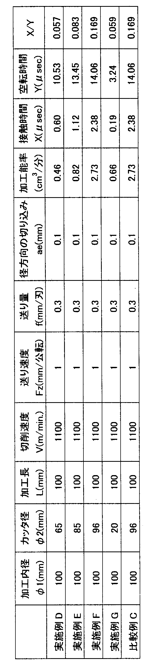
- Table 4 shows the cutting conditions, etc., when the average particle size of the CBN constituting the cutting tip, the thermal conductivity of the cutting tip, and the volume of chips removed from the work piece by cutting are 50 cm 3 .
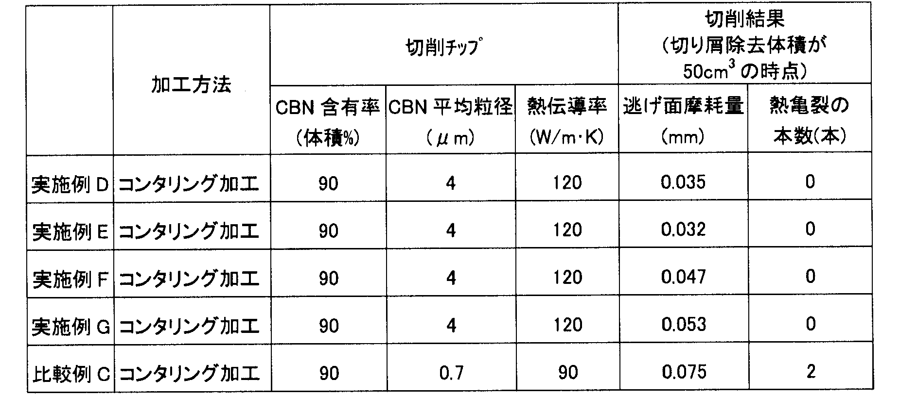
- Table 5 shows the flank wear amount of the cutting tip and the number of thermal cracks.
- the blade contact time X and idling time Y were changed by adjusting the cutter diameter to be used.
- the binder constituting the CBN sintered bodies of Examples D to G contains at least one substance selected from the group consisting of WC (tungsten carbide), Co (cobalt) compound, and Al (aluminum) compound. is doing.
- Examples F and G in which the contact time X is out of the range of 0.2 ⁇ sec or more and 2 ⁇ sec or less and X / Y is out of the range of 0.06 or more and 0.16 or less are the above Examples D and The flank wear amount is larger than E. From this result, the contact time and idle time between the cutting tip and the workpiece are optimized by setting the contact time X to 0.2 ⁇ sec to 2 ⁇ sec and X / Y to 0.06 to 0.16. It was confirmed that high-efficiency machining can be realized while significantly reducing the wear rate of the cutting tip.
- Comparative Example C in which the average particle size of CBN particles is 0.7 ⁇ m, has the same flank wear amount as that of Example F in which the average particle size of CBN particles is 3 ⁇ m or more under the same processing conditions.
- the cutting tip of Comparative Example C in which the CBN particles are finer than the cutting tip of Example F, has a low thermal conductivity, so that the heat radiation effect of the cutting heat generated during cutting is smaller than that of Example F. It is considered that a thermal crack occurred at the cutting edge because the temperature range of the history became large. From this result, it is confirmed that by setting the average particle size of the CBN particles constituting the cutting tip to 3 ⁇ m or more, the thermal conductivity of the cutting tip can be improved and the occurrence of thermal cracks at the cutting edge can be suppressed.
- the method of processing difficult-to-cut cast iron of the present invention can be applied particularly advantageously to processing of hard-to-cut cast iron that requires both a longer life of the cutting tip and an improvement in cutting speed.
Landscapes
- Engineering & Computer Science (AREA)
- Mechanical Engineering (AREA)
- Cutting Tools, Boring Holders, And Turrets (AREA)
- Ceramic Products (AREA)
- Drilling And Boring (AREA)
Abstract
Description
以下、実施例1について説明する。CBN焼結体からなる切削チップを用いて、難削鋳鉄であるFCD450からなる被加工物に対してコンタリング内径加工および連続内径加工を実施することにより、切削チップの摩耗量に及ぼす加工方法、切削チップのCBN含有率および切削チップの熱伝導率の影響を調査する実験を行なった。表1にコンタリング内径加工の加工条件、表2に連続内径加工の加工条件を示す。また、切削チップのCBN含有率および熱伝導率、ならびに切削加工により被加工物から除去された切り屑の体積が50cm3となった時点における切削チップの逃げ面摩耗量を表3に示す。なお、切削チップは型番CNGA120408を採用した。また、実施例A~Cおよび比較例AのCBN焼結体を構成する結合材は、WC、Co化合物およびAl化合物を少なくとも含有している。一方、比較例BのCBN焼結体の結合材は、Ti化合物およびAl化合物を少なくとも含有している。

次に、実施例2について説明する。CBN焼結体からなる切削チップを用いて、難削鋳鉄であるFC250からなる被加工物に対してコンタリング内径加工を実施することにより、切削チップの摩耗量および熱亀裂の発生に及ぼすCBNの平均粒径および切削チップの熱伝導率、ならびに切削チップと被加工物との接触時間および空転時間の影響を調査する実験を行なった。切削条件等を表4に、切削チップを構成するCBNの平均粒径および切削チップの熱伝導率、ならびに切削加工により被加工物から除去された切り屑の体積が50cm3となった時点におけるの切削チップの逃げ面摩耗量および熱亀裂の本数を表5に示す。なお、刃先の接触時間Xおよび空転時間Yは、使用するカッタ径を調整することにより変更した。また、実施例D~GのCBN焼結体を構成する結合材は、WC(炭化タングステン)、Co(コバルト)化合物、Al(アルミニウム)化合物からなる群から選択される少なくとも1種の物質を含有している。
Claims (4)
- 難削鋳鉄からなる被加工物(20)を準備する工程と、
切削チップ(11)を有する切削工具(10)を用いて前記被加工物(20)を切削加工する工程とを備え、
前記被加工物(20)を切削加工する工程では、前記切削工具(10)が自転しつつ公転することにより前記切削チップ(11)が前記被加工物(20)に対して断続的に接触し、
前記切削チップ(11)はCBNの含有率が85体積%以上の焼結体からなり、
前記切削チップ(11)の熱伝導率は100W/(m・K)以上である、難削鋳鉄の加工方法。 - 前記被加工物(20)を切削加工する工程においては、前記切削チップ(11)と前記被加工物(20)とが接触している時間である接触時間をX、前記切削チップ(11)が前記被加工物(20)と離れた状態で空転する時間である空転時間をYとした場合、Xは0.2μsec以上2μsec以下、X/Yは0.06以上0.16以下であることを特徴とする、請求の範囲第1項に記載の難削鋳鉄の加工方法。
- 前記切削チップ(11)の熱伝導率は120W/(m・K)以上であり、
前記被加工物(20)を切削加工する工程における切削速度は1000m/min.以上であることを特徴とする、請求の範囲第1項に記載の難削鋳鉄の加工方法。 - 前記切削チップ(11)を構成するCBN粒子の平均粒径は3μm以上である、請求の範囲第1項に記載の難削鋳鉄の加工方法。
Priority Applications (6)
| Application Number | Priority Date | Filing Date | Title |
|---|---|---|---|
| CN201080048269.7A CN102596462B (zh) | 2009-11-02 | 2010-10-28 | 用于加工难切削铸铁的方法 |
| CA 2779394 CA2779394C (en) | 2009-11-02 | 2010-10-28 | Method for processing difficult-to-cut cast iron |
| EP10826814.5A EP2497591B1 (en) | 2009-11-02 | 2010-10-28 | Method for processing difficult-to-cut cast iron |
| JP2011538480A JPWO2011052682A1 (ja) | 2009-11-02 | 2010-10-28 | 難削鋳鉄の加工方法 |
| IN3424DEN2012 IN2012DN03424A (ja) | 2009-11-02 | 2010-10-28 | |
| US13/504,422 US9016987B2 (en) | 2009-11-02 | 2010-10-28 | Method for processing difficult-to-cut cast iron |
Applications Claiming Priority (2)
| Application Number | Priority Date | Filing Date | Title |
|---|---|---|---|
| JP2009251869 | 2009-11-02 | ||
| JP2009-251869 | 2009-11-02 |
Publications (1)
| Publication Number | Publication Date |
|---|---|
| WO2011052682A1 true WO2011052682A1 (ja) | 2011-05-05 |
Family
ID=43922104
Family Applications (1)
| Application Number | Title | Priority Date | Filing Date |
|---|---|---|---|
| PCT/JP2010/069172 Ceased WO2011052682A1 (ja) | 2009-11-02 | 2010-10-28 | 難削鋳鉄の加工方法 |
Country Status (8)
| Country | Link |
|---|---|
| US (1) | US9016987B2 (ja) |
| EP (1) | EP2497591B1 (ja) |
| JP (1) | JPWO2011052682A1 (ja) |
| KR (1) | KR20120081211A (ja) |
| CN (1) | CN102596462B (ja) |
| CA (1) | CA2779394C (ja) |
| IN (1) | IN2012DN03424A (ja) |
| WO (1) | WO2011052682A1 (ja) |
Cited By (1)
| Publication number | Priority date | Publication date | Assignee | Title |
|---|---|---|---|---|
| JP2020037148A (ja) * | 2018-09-03 | 2020-03-12 | 有限会社芹沢製作所 | 多角形形状の加工方法及び加工装置 |
Families Citing this family (3)
| Publication number | Priority date | Publication date | Assignee | Title |
|---|---|---|---|---|
| CN103752922A (zh) * | 2014-01-13 | 2014-04-30 | 邵阳维克液压股份有限公司 | 柱塞泵变量壳体上的轴瓦座圆柱面加工方法 |
| US20170120348A1 (en) * | 2015-10-30 | 2017-05-04 | Ford Motor Company | Engine bore milling process |
| CN116987943B (zh) * | 2018-09-19 | 2025-10-10 | 住友电气工业株式会社 | 立方氮化硼烧结体以及包括该立方氮化硼烧结体的切削工具 |
Citations (9)
| Publication number | Priority date | Publication date | Assignee | Title |
|---|---|---|---|---|
| JPS6015109A (ja) * | 1983-07-06 | 1985-01-25 | 住友電気工業株式会社 | セラミツク,岩石の高速切削加工法 |
| JPH01316110A (ja) * | 1988-06-13 | 1989-12-21 | Sumitomo Electric Ind Ltd | 穴明け加工方法 |
| JPH0839321A (ja) | 1994-07-28 | 1996-02-13 | Toyota Motor Corp | 回転切削工具および切削方法 |
| JPH10277831A (ja) * | 1997-04-04 | 1998-10-20 | Sumitomo Electric Ind Ltd | フライス用切削工具 |
| JPH11347803A (ja) | 1998-06-01 | 1999-12-21 | Mitsubishi Materials Corp | スローアウェイチップ及び突き加工用カッタ |
| JP2000042823A (ja) * | 1998-05-26 | 2000-02-15 | Sumitomo Electric Ind Ltd | フライス用切削工具とその製造方法 |
| JP2006181702A (ja) * | 2004-12-28 | 2006-07-13 | Sumitomo Electric Hardmetal Corp | 刃先交換式チップとそれを用いたエンドミル |
| WO2007039955A1 (ja) * | 2005-10-04 | 2007-04-12 | Sumitomo Electric Hardmetal Corp. | 高品位表面性状加工用cBN焼結体及びcBN焼結体切削工具 |
| WO2007057995A1 (ja) * | 2005-11-18 | 2007-05-24 | Sumitomo Electric Hardmetal Corp. | 高品位表面性状加工用cBN焼結体及びcBN焼結体切削工具およびこれを用いた切削加工方法 |
Family Cites Families (5)
| Publication number | Priority date | Publication date | Assignee | Title |
|---|---|---|---|---|
| JP3479688B2 (ja) * | 2001-03-02 | 2003-12-15 | 独立行政法人産業技術総合研究所 | 難削材切削工具 |
| KR100502585B1 (ko) * | 2002-07-08 | 2005-07-20 | 일진디스플레이(주) | 주철 절삭용 고경도 소결체 및 그 제조방법 |
| IL167779A (en) * | 2005-03-31 | 2013-09-30 | Hanita Metal Works Ltd | Milling balls |
| US8714890B2 (en) * | 2007-02-09 | 2014-05-06 | The Boeing Company | Cutter for drilling and reaming |
| US8256092B1 (en) * | 2008-01-30 | 2012-09-04 | Makino Inc. | Method for helical boring |
-
2010
- 2010-10-28 KR KR20127012208A patent/KR20120081211A/ko not_active Ceased
- 2010-10-28 JP JP2011538480A patent/JPWO2011052682A1/ja not_active Withdrawn
- 2010-10-28 IN IN3424DEN2012 patent/IN2012DN03424A/en unknown
- 2010-10-28 CN CN201080048269.7A patent/CN102596462B/zh active Active
- 2010-10-28 US US13/504,422 patent/US9016987B2/en active Active
- 2010-10-28 EP EP10826814.5A patent/EP2497591B1/en active Active
- 2010-10-28 CA CA 2779394 patent/CA2779394C/en not_active Expired - Fee Related
- 2010-10-28 WO PCT/JP2010/069172 patent/WO2011052682A1/ja not_active Ceased
Patent Citations (9)
| Publication number | Priority date | Publication date | Assignee | Title |
|---|---|---|---|---|
| JPS6015109A (ja) * | 1983-07-06 | 1985-01-25 | 住友電気工業株式会社 | セラミツク,岩石の高速切削加工法 |
| JPH01316110A (ja) * | 1988-06-13 | 1989-12-21 | Sumitomo Electric Ind Ltd | 穴明け加工方法 |
| JPH0839321A (ja) | 1994-07-28 | 1996-02-13 | Toyota Motor Corp | 回転切削工具および切削方法 |
| JPH10277831A (ja) * | 1997-04-04 | 1998-10-20 | Sumitomo Electric Ind Ltd | フライス用切削工具 |
| JP2000042823A (ja) * | 1998-05-26 | 2000-02-15 | Sumitomo Electric Ind Ltd | フライス用切削工具とその製造方法 |
| JPH11347803A (ja) | 1998-06-01 | 1999-12-21 | Mitsubishi Materials Corp | スローアウェイチップ及び突き加工用カッタ |
| JP2006181702A (ja) * | 2004-12-28 | 2006-07-13 | Sumitomo Electric Hardmetal Corp | 刃先交換式チップとそれを用いたエンドミル |
| WO2007039955A1 (ja) * | 2005-10-04 | 2007-04-12 | Sumitomo Electric Hardmetal Corp. | 高品位表面性状加工用cBN焼結体及びcBN焼結体切削工具 |
| WO2007057995A1 (ja) * | 2005-11-18 | 2007-05-24 | Sumitomo Electric Hardmetal Corp. | 高品位表面性状加工用cBN焼結体及びcBN焼結体切削工具およびこれを用いた切削加工方法 |
Cited By (2)
| Publication number | Priority date | Publication date | Assignee | Title |
|---|---|---|---|---|
| JP2020037148A (ja) * | 2018-09-03 | 2020-03-12 | 有限会社芹沢製作所 | 多角形形状の加工方法及び加工装置 |
| JP7141619B2 (ja) | 2018-09-03 | 2022-09-26 | 有限会社芹沢製作所 | 多角形形状の加工方法及び加工装置 |
Also Published As
| Publication number | Publication date |
|---|---|
| JPWO2011052682A1 (ja) | 2013-03-21 |
| CN102596462A (zh) | 2012-07-18 |
| US9016987B2 (en) | 2015-04-28 |
| CN102596462B (zh) | 2015-03-04 |
| CA2779394A1 (en) | 2011-05-05 |
| CA2779394C (en) | 2014-06-10 |
| EP2497591A1 (en) | 2012-09-12 |
| IN2012DN03424A (ja) | 2015-10-23 |
| EP2497591B1 (en) | 2018-08-22 |
| EP2497591A4 (en) | 2017-02-08 |
| KR20120081211A (ko) | 2012-07-18 |
| US20120219373A1 (en) | 2012-08-30 |
Similar Documents
| Publication | Publication Date | Title |
|---|---|---|
| JP2014217933A (ja) | cBN切削工具 | |
| JP5603954B2 (ja) | 超硬要素、その使用方法及びその製造方法 | |
| WO2011052682A1 (ja) | 難削鋳鉄の加工方法 | |
| CN110981497A (zh) | 一种高导热高耐磨的氮化硅陶瓷及其制备方法和应用 | |
| CN104923839B (zh) | 一种铝硅壳体加工方法 | |
| KR100942771B1 (ko) | 서멧 리머 | |
| JP2009045715A (ja) | 高圧クーラントを用いた切削加工方法 | |
| CN1200127C (zh) | 以纳米TiN改性的TiC或Ti(C,N)基金属陶瓷刀具、该刀具的制造工艺及刀具的使用方法 | |
| JP2017087373A (ja) | 回転切削工具 | |
| CN113732366A (zh) | 一种深小孔内壁超声振动加工刀具及其制备方法 | |
| JP2015091627A (ja) | cBN切削工具 | |
| Li et al. | Optimized for Silicon Wafer Dicing Blade Machining and Grinding Parameters of Structure | |
| JP2012206212A (ja) | サーキュラーソー | |
| CN116372827A (zh) | 一种金刚石烧结砂轮的修整方法和装置 | |
| Sun et al. | Surface Quality Analysis of Laser-Induced Assisted Grinding of Single-Crystal Silicon | |
| CN208484034U (zh) | M型金属基金刚石锯片 | |
| JP2015223654A (ja) | 微細工具の製造方法及び微細工具 | |
| Yigit et al. | General tool conditions for Green machining | |
| CN220547684U (zh) | 一种铣槽刀具 | |
| CN102873364B (zh) | 一种在玻封合金上加工微孔的方法 | |
| CN119839349A (zh) | 用于卧式加工中心的钨钢铣刀及其制备方法 | |
| JP2016190317A (ja) | cBN切削工具 | |
| CN205289891U (zh) | 一种基于超声波马达原理的旋转式可转位刀片铣削系统 | |
| CN205237099U (zh) | 一种基于超声波马达原理的旋转式可转位刀片车削系统 | |
| CN104384721A (zh) | 一种pdc片的倒角加工方法 |
Legal Events
| Date | Code | Title | Description |
|---|---|---|---|
| WWE | Wipo information: entry into national phase |
Ref document number: 201080048269.7 Country of ref document: CN |
|
| 121 | Ep: the epo has been informed by wipo that ep was designated in this application |
Ref document number: 10826814 Country of ref document: EP Kind code of ref document: A1 |
|
| WWE | Wipo information: entry into national phase |
Ref document number: 2011538480 Country of ref document: JP |
|
| WWE | Wipo information: entry into national phase |
Ref document number: 3424/DELNP/2012 Country of ref document: IN |
|
| WWE | Wipo information: entry into national phase |
Ref document number: 13504422 Country of ref document: US |
|
| WWE | Wipo information: entry into national phase |
Ref document number: 2779394 Country of ref document: CA |
|
| NENP | Non-entry into the national phase |
Ref country code: DE |
|
| ENP | Entry into the national phase |
Ref document number: 20127012208 Country of ref document: KR Kind code of ref document: A |
|
| WWE | Wipo information: entry into national phase |
Ref document number: 2010826814 Country of ref document: EP |