WO2011055494A1 - 燃焼プレート - Google Patents
燃焼プレート Download PDFInfo
- Publication number
- WO2011055494A1 WO2011055494A1 PCT/JP2010/006155 JP2010006155W WO2011055494A1 WO 2011055494 A1 WO2011055494 A1 WO 2011055494A1 JP 2010006155 W JP2010006155 W JP 2010006155W WO 2011055494 A1 WO2011055494 A1 WO 2011055494A1
- Authority
- WO
- WIPO (PCT)
- Prior art keywords
- flame
- combustion
- holes
- hole
- regular hexagon
- Prior art date
- Legal status (The legal status is an assumption and is not a legal conclusion. Google has not performed a legal analysis and makes no representation as to the accuracy of the status listed.)
- Ceased
Links
Images



Classifications
-
- F—MECHANICAL ENGINEERING; LIGHTING; HEATING; WEAPONS; BLASTING
- F23—COMBUSTION APPARATUS; COMBUSTION PROCESSES
- F23D—BURNERS
- F23D14/00—Burners for combustion of a gas, e.g. of a gas stored under pressure as a liquid
- F23D14/46—Details
- F23D14/48—Nozzles
- F23D14/58—Nozzles characterised by the shape or arrangement of the outlet or outlets from the nozzle, e.g. of annular configuration
-
- F—MECHANICAL ENGINEERING; LIGHTING; HEATING; WEAPONS; BLASTING
- F23—COMBUSTION APPARATUS; COMBUSTION PROCESSES
- F23D—BURNERS
- F23D14/00—Burners for combustion of a gas, e.g. of a gas stored under pressure as a liquid
- F23D14/26—Burners for combustion of a gas, e.g. of a gas stored under pressure as a liquid with provision for a retention flame
-
- F—MECHANICAL ENGINEERING; LIGHTING; HEATING; WEAPONS; BLASTING
- F23—COMBUSTION APPARATUS; COMBUSTION PROCESSES
- F23D—BURNERS
- F23D14/00—Burners for combustion of a gas, e.g. of a gas stored under pressure as a liquid
- F23D14/34—Burners specially adapted for use with means for pressurising the gaseous fuel or the combustion air
-
- F—MECHANICAL ENGINEERING; LIGHTING; HEATING; WEAPONS; BLASTING
- F23—COMBUSTION APPARATUS; COMBUSTION PROCESSES
- F23D—BURNERS
- F23D14/00—Burners for combustion of a gas, e.g. of a gas stored under pressure as a liquid
- F23D14/46—Details
- F23D14/72—Safety devices, e.g. operative in case of failure of gas supply
- F23D14/74—Preventing flame lift-off
-
- F—MECHANICAL ENGINEERING; LIGHTING; HEATING; WEAPONS; BLASTING
- F23—COMBUSTION APPARATUS; COMBUSTION PROCESSES
- F23D—BURNERS
- F23D2203/00—Gaseous fuel burners
- F23D2203/10—Flame diffusing means
- F23D2203/102—Flame diffusing means using perforated plates
- F23D2203/1023—Flame diffusing means using perforated plates with specific free passage areas
-
- F—MECHANICAL ENGINEERING; LIGHTING; HEATING; WEAPONS; BLASTING
- F23—COMBUSTION APPARATUS; COMBUSTION PROCESSES
- F23D—BURNERS
- F23D2210/00—Noise abatement
Definitions
- the present invention is a combustion plate mainly used in an all-primary combustion burner provided in a heat source device for hot water supply or heating, in which a number of flame holes for ejecting premixed gas are formed in a ceramic plate body. About.
- Patent Document 1 Conventionally, as a combustion plate of this type, according to Patent Document 1, three types of large, medium, and small flame holes are dispersed in a lattice shape over the entire combustion region of the plate body, and a large flame is used.
- the hole is located at the center of the four adjacent small flame holes and at the center of the four adjacent medium flame holes, and each small flame hole is formed in the middle of the two adjacent medium flame holes, It is known that a concave hole having a size including a part of each small flame hole concentric with each large flame hole is formed on the surface of the plate body. According to this, it is said that it is possible to eliminate combustion resonance noise and instability during high load combustion that are likely to occur when all the flame holes have the same diameter.
- the diameter of the large flame hole is 1.9 mm
- the diameter of the medium flame hole is 1.3 mm
- the diameter of the small flame hole is 1.0 mm
- the diameter 2 is concentric with the large flame hole.
- Four small flame holes are arranged at equal intervals on the circumference of 4 mm, and the phase of the small flame holes on the circumference of 3.4 mm concentric with the large flame hole is shifted by 45 ° and 4 at equal intervals.
- a combustion plate is described comprising two flaming holes.
- the opening ratio (ratio of the total area of all the flame holes with respect to the total area of the combustion area of a plate main body) of a flame hole is comparatively set by the relationship which arranges the flame holes of a different diameter in a grid
- the aperture ratio of the flame holes becomes about 26%. Therefore, there is a problem that the passage resistance of the combustion plate is increased, the load of the fan supplying the primary air to the burner is increased, and the fan noise is increased.
- the present invention has an object to provide a combustion plate that can eliminate combustion resonance noise and instability during high-load combustion, and can ensure a large aperture ratio of the flame holes. .
- the present invention is a combustion plate for an all-primary combustion burner, in which a large number of flame holes for ejecting premixed gas are formed in a ceramic plate body having the same diameter.
- the six flame holes are arranged in a positional relationship in which a regular hexagon is formed, and the three adjacent flame holes are uniformly formed over the entire surface of the combustion region of the plate body in a positional relationship in which three adjacent flame holes form a regular triangle.
- a flame hole group consisting of a single flame hole at the center of the regular hexagon, one flame hole surrounding each regular hexagon and one flame hole in the middle of each side
- the flame holes having the same diameter are arranged in a positional relationship in which three adjacent flame holes form an equilateral triangle, so that the flame holes are arranged most densely within a manufacturable range of the combustion plate.
- the aperture ratio of the flame holes can be greatly increased compared to the conventional one, the passage resistance of the combustion plate can be reduced, the burden on the fan supplying the primary air to the burner is reduced, and the fan noise is reduced. Can be reduced.
- the premixed gas ejected from the six flame holes in the regular hexagonal position of each unit flame group has a velocity component toward the center of the concave hole, premixing in the normal direction of the plate surface is performed.
- the effect of reducing the gas ejection speed is obtained. Therefore, the shape of the collective flame formed by the combustion of the premixed gas ejected from the concave holes of the unit flame hole group becomes a mountain shape without a steep rise, and the flame holding effect of suppressing the flame lift during high load combustion is achieved. can get. Therefore, although all the flame holes have the same diameter, the stability of combustion during high load combustion is ensured.
- the collective flames formed by the combustion of the premixed gas ejected from the concave holes of the unit flame hole groups are adjacent to each other, the collective flames resonate to generate a large combustion resonance sound.
- the large regular hexagonal flame hole exists between each unit flame hole group, a flame separated from the collective flame is formed by the combustion of the premixed gas ejected from the flame hole.
- resonance between the collective flames is suppressed, and combustion resonance noise is reduced.
- the bottom surface of the concave hole is formed into a tapered surface that becomes gradually deeper toward the center and / or the concave hole is formed so as to be reduced in diameter toward the bottom surface, the regular hexagon of each unit flame hole group is formed.
- the premixed gas ejected from the six flame holes in the positional relationship is advantageous in that it tends to have a velocity component toward the center of the concave hole.
- the depth of the lowermost part of the peripheral surface of the concave hole is desirably 1 mm or more and 3 mm or less.
- a regular hexagon formed by the six flame holes of the unit flame group is a predetermined diagonal direction or a direction opposite to a predetermined opposite side as a column direction, and the unit flame groups arranged in the column direction. Blocking at least a part of the twelve flame holes located on the large regular hexagon surrounding each unit flame hole group belonging to the selected row selected at a predetermined interval in the direction perpendicular to the row direction Is desirable. According to this, a recirculation zone in which a part of the premixed gas ejected from the concave holes of the unit flame hole group circulates around the flame hole closing portion is generated, and the flame holding effect is enhanced. Therefore, the stability of combustion during high load combustion is further improved.
- the closed flame hole is a flame hole located at each corner of the large regular hexagon. According to this, the same flame holding effect as that obtained by closing all the flame holes located on the large regular hexagon can be obtained. And compared with what closes all the flame holes located on a big regular hexagon, the aperture ratio of a flame hole can be enlarged and is advantageous.
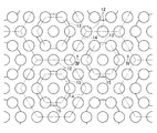
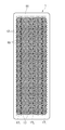
- FIG. 3 is an enlarged plan view of a part of the combustion plate of FIG. 2.
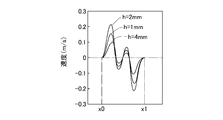
- wire of FIG. The graph which shows the velocity component to the concave hole center direction of the premixed gas ejected from the flame hole of a unit flame group.
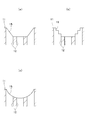
- Sectional drawing which shows the modification of the shape of a concave hole.
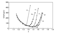
- the figure which shows the velocity vector of the premixed gas ejected from the combustion plate of 2nd-6th embodiment. 9 is a graph showing the result of a combustion test performed using the combustion plate of the first to sixth embodiments.
- FIG. 1 shows a heat source device for hot water supply or heating provided with an all primary combustion burner 2 using a combustion plate 1.
- the fan 3 is connected to the burner 2 through the ventilation path 3a.
- the gas nozzle 4 which injects fuel gas to the ventilation path 3a is provided.
- the premixed gas of the primary air supplied from the fan 3 and the fuel gas injected from the gas nozzle 4 is jetted through the combustion plate 1 and burned, and the heat exchanger 5 for hot water supply or heating is made by the combustion gas. I try to heat it.
- the fan 3 is controlled so that the primary air amount is larger than the stoichiometric air amount required for complete combustion of the fuel gas. Therefore, a premixed gas having an excess air ratio (primary air amount / stoichiometric air amount) larger than 1 is ejected through the combustion plate 1 and all primary combustion occurs.
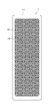
- the combustion plate 1 is formed by forming a large number of flame holes 12 for ejecting premixed gas in a ceramic plate body 11 having a rectangular shape in plan view.
- the flame holes 12 having the same diameter are formed uniformly over the entire combustion region of the plate body 11 in a positional relationship in which the three adjacent flame holes 12 form an equilateral triangle.
- the thickness of the plate body 11 is 13 mm.
- the diameter of the flame hole 12 exceeds 1.5 mm, backfire is likely to occur.
- the diameter of the flame hole 12 is 0.8 mm. It is desirable to set to ⁇ 1.5 mm.
- the center-to-center distance (pitch) of the flame holes 12 is set to about 1.5 times the diameter of the flame holes 12, which is the minimum value necessary for ensuring the strength. Thereby, the flame holes 12 can be arranged most densely within a manufacturable range.
- the diameter of the flame holes 12 is set to 1.25 mm, and the pitch is set to 1.9 mm.
- the aperture ratio of the flame hole 12 is 36%, and the aperture ratio is significantly increased as compared with that described as an example in Patent Document 1 described above. Therefore, the passage resistance of the combustion plate 1 is reduced, the burden on the fan 3 is reduced, and fan noise during high load combustion is effectively reduced.
- a group that surrounds the regular hexagon 13 and is adjacent to each other with a large regular hexagon 14 sandwiching one flame hole 12 at each corner and one flame hole 12 in the middle of each side. Is a unit flame group.
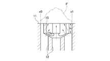
- the concave hole 15 having a diameter smaller than that of the circle inscribed in the six flame holes 12 is formed.
- the diameter of the concave hole 15 is set to 4 mm, and the inner half of each flame hole 12 in the positional relationship forming the regular hexagon 13 enters the concave hole 15.
- the premixed gas ejected from each flame hole 12 in the positional relationship forming the regular hexagon 13 of the unit flame hole group has a velocity component toward the center of the concave hole 15. Therefore, the effect of reducing the ejection speed of the premixed gas in the normal direction of the plate surface can be obtained.
- the shape of the collective flame F formed by the combustion of the premixed gas ejected from the concave holes 15 of the unit flame hole group becomes a mountain shape without a steep rise, and the flame lift during high load combustion is suppressed. A flame effect is obtained. Therefore, although all the flame holes 12 have the same diameter, the stability of combustion during high load combustion is ensured.
- the collective flames F formed by the combustion of the premixed gas ejected from the concave holes 15 of the unit flame hole groups are adjacent to each other, the collective flames F resonate to generate a large combustion resonance sound.
- the flame holes 12 on the large regular hexagon 14 are present between the unit flame groups, so that they are separated from the collective flame F by the combustion of the premixed gas ejected from the flame holes 12. As a result, the resonance between the collective flames F is suppressed and the combustion resonance noise is reduced.
- the bottom surface of the recessed hole 15 is formed on the tapered surface 15a that gradually becomes deeper toward the center. According to this, the velocity component in the center direction of the concave hole 15 can be more effectively imparted to the premixed gas ejected from each flame hole 12 in the positional relationship forming the regular hexagon 13 of the unit flame hole group.
- each flame hole has a depth h of 1 mm, 2 mm, and 4 mm at the bottom of the peripheral surface of the concave hole 15.
- the result is shown in FIG.
- the horizontal axis in FIG. 5 indicates the position from x0 to x1 in FIG. 4, and the vertical axis speed is plus the component in the central direction toward the right in FIG. 4, and toward the central direction toward the left.
- the component of is expressed as minus.
- the value of the above flow rate is equivalent to the case where a premixed gas having a fuel gas of methane and an excess air ratio of 1.6 is supplied to the combustion plate 1 at an input of 12 kW.
- the bottom surface 15a of the concave hole 15 is formed in a taper surface, as shown to Fig.6 (a), it forms so that the concave hole 15 may be diameter-reduced gradually toward a bottom surface, As shown in FIG. 6 (b), the concave hole 15 is formed so as to be gradually reduced in diameter toward the bottom surface, or as shown in FIG. 6 (c), the concave hole 15 is reduced in a round shape toward the bottom surface. It is also possible to make it easy to give a velocity component in the central direction of the concave hole 15 to the premixed gas ejected from each flame hole 12 in the positional relationship forming the regular hexagon 13 of the unit flame hole group. It is. Further, the concave hole 15 may be formed so as to have a diameter reduced toward the bottom surface, and the bottom surface of the concave hole 15 may be formed into a tapered surface.
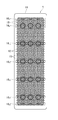
- the second to fifth embodiments are different from the first embodiment in that the right and left diagonal directions (the short side of the plate body 11) are shown in the figure of the regular hexagon 13 formed by the six flame holes 12 of the unit flame group.
- Direction is selected as a column direction, and a plurality of columns are selected from the column 16 of unit flame hole groups arranged in the column direction at a predetermined interval in the direction orthogonal to the column direction (longitudinal direction of the plate body 11). That is, at least a part of the twelve flame holes 12 located on the large regular hexagon 14 surrounding each unit flame group belonging to the selected row is closed.
- the size of the combustion region, the diameter and pitch of the flame holes 12, the diameter of the concave holes 15, and the depth h are the same as in the first embodiment.
- the closed flame hole 12, that is, the non-drilled portion of the flame hole 12 formed in the first embodiment is shown in black.
- the fourth row 16 4 the 12th row counted from one end (upper end in FIG. 7) of the plate body 11 in the unit flame hole group row 16.
- 16 12 , the 20th column 16 20 , the 28th column 16 28 and the 36th column 16 36 are selected columns, and 12 is positioned on the large regular hexagon 14 surrounding each unit flame group belonging to each selected column. All the flame holes 12 are closed.
- the aperture ratio of the flame hole 12 of the second embodiment is 32%.
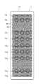
- each unit fire hole belonging to respective selected column All twelve flame holes 12 located on the large regular hexagon 14 surrounding the group are closed.
- the aperture ratio of the flame hole 12 of the third embodiment is 30%.
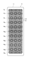
- the eighth column 16 8 and 32 th column in addition to the selected column of the third embodiment as the selected column 16 32 is selected, and all the 12 flame holes 12 located on the large regular hexagon 14 surrounding each unit flame group belonging to each of these selected columns are closed.
- the aperture ratio of the flame hole 12 of the fourth embodiment is 28%.
- the three flame holes 12 located between the centers of the unit flame groups belonging to the first and 39th rows 16 1 and 16 39 are also closed.
- the same column as the fourth embodiment is selected as the selection column, but all the flames on the large regular hexagon 14 surrounding each unit flame group belonging to each of these selection columns.
- a total of six flame holes 12 positioned at each corner of the regular hexagon 14 are closed.
- two of the three flame holes 12 that are close to the unit flame hole group are used.
- the flame hole 12 is also closed.
- the aperture ratio of the flame hole 12 of the fifth embodiment is 32%.
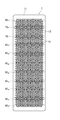
- the flame holes 12 positioned at the corners of all large regular hexagons 14 surrounding all the unit flame hole groups are closed.
- the aperture ratio of the flame hole 12 of the sixth embodiment is 30%.
- a combustion test was performed using the combustion plate 1 of the first to sixth embodiments.
- the fuel gas is methane
- the input (combustion amount) is 12 kW (2400 kW / m 2 in terms of flame load)
- the excess air ratio of the premixed gas is changed, and the CO concentration in the theoretical dry combustion gas COaf was measured.
- the premixed gas with an even excess air ratio is supplied to the entire region of the combustion plate 1.
- the combustion plate 1 In an actual burner, due to insufficient mixing of the fuel gas and the primary air, the combustion plate 1 There are variations in the excess air ratio of the premixed gas in each part, and the excess air ratio may deviate from a required target value during combustion due to a delay in the response of the fan speed to the input change. Therefore, it is better that the range of the excess air ratio for stable combustion is as wide as possible.
- FIG. 13 shows combustion test results.
- the a line is the first embodiment
- the b line is the second embodiment
- the c line is the third embodiment
- the d line is the fourth embodiment
- the e line is the fifth embodiment.
- F line is the sixth embodiment.
- the lower limit of the range of the excess air ratio ⁇ for good combustion at COaf ⁇ 400 ppm is about 1.12 in any of the first to sixth embodiments
- the upper limit is 1.42 in the first embodiment
- the flame holes 12 positioned at the corners of the large regular hexagon may be closed.
- the second embodiment and the fifth embodiment have the same opening ratio (32%)
- the range of the excess air ratio for good combustion is larger than that of the second embodiment (b line in FIG. 13).
- the fifth embodiment (e line in FIG. 13) is wider and better.
- the excess air ratio is 1.3 or less.
- a high frequency combustion resonance was generated. This is because resonance of the collective flames of each unit flame group occurs across the entire area of the combustion plate 1.
- each corner of each large regular hexagon 14 surrounding each of the unit flame groups belonging to the selected column is almost the same as in the sixth embodiment. Therefore, in order to suppress the generation of combustion resonance noise, the number of non-selected rows existing between each selected row needs to be three or more as in the second to fifth embodiments.
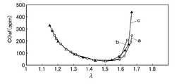
- the combustion plate 1 of the fifth embodiment was performed using the combustion plate 1 of the fifth embodiment, with inputs of 12 kW and 13.8 kW, respectively, and the results shown in FIG. 14 were obtained.
- the a line in FIG. 14 shows the result at 12 kW
- the b line shows the result at 13.8 kW.
- wire of FIG. 14 has shown the result of having performed the combustion test by using the combustion plate described as an Example in patent document 1 and making input 12kW.
- the range of the excess air ratio ⁇ for good combustion at COaf ⁇ 400 ppm is narrower than 1.14 to 1.66 during 13.8 kW combustion and 1.12 to 1.69 during 12 kW combustion.
- the flame hole opening ratio of the example of Patent Document 1 is 26%
- the flame hole opening ratio of the fifth embodiment is as large as 32%, reducing the burden on the fan 3 and reducing fan noise. Become.
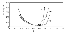
- combustion plate 1 of the fifth embodiment and the depth h of the concave hole 15 are changed from 2 mm of the fifth embodiment to 1 mm, and the other combustion is the same as that of the fifth embodiment except that it is the same.
- a combustion plate of a second modified example in which the diameter of the concave hole 15 is changed from 4 mm of the fifth embodiment to 3.2 mm and the depth h is 1 mm, and the others are the same as those of the fifth embodiment A combustion test was conducted with an input of 12 kW, and the results shown in FIG. 15 were obtained.
- the a line in FIG. 15 is the fifth embodiment, the b line is the first modification, and the c line is the second modification. From this result, it can be seen that even if the depth h of the concave hole 15 is 1 mm and the diameter of the concave hole 15 is 3.2 mm, the same degree of flame holding effect can be obtained.
- a plurality of rows are selected from the rows 17 of the groups at a predetermined interval in the direction orthogonal to the row direction (the short direction of the plate body 11), and a large regular six surrounding each unit flame group belonging to these selected rows.
- the flame hole 12 located at each corner of the square 14 is closed. Even in the seventh embodiment, the same flame holding effect as in the fifth embodiment can be obtained.
- the opposite direction of the opposite hexagon 13 formed by the six flame holes of the unit flame group is the column direction, and each corner of every large regular hexagon 14 surrounding each of the unit flame groups belonging to the selected row.
- the flame hole 12 located at is closed, if the number of non-selected rows existing between the selected rows is one, it is almost the same as in the sixth embodiment, and combustion resonance noise is generated. Therefore, in the seventh embodiment, the lateral direction end first column 17 1 counted from the end (left end in FIG. 16) of the plate body 11, a fourth column 17 4, 7-th row 17 7 selected column So that there are two unselected columns between each selected column.
- the short direction of the plate body 11 which is one of the diagonal directions of the regular hexagon 13 formed by the six flame holes of the unit flame hole group is the row direction.
- the selected columns are selected at a predetermined interval (an interval such that at least three non-selected columns exist between the selected columns), and the 12 regular hexagons surrounding each unit flame hole group belonging to the selected column are selected. You may obstruct
- the longitudinal direction of the plate main body 11 which is one of the opposing directions of the regular hexagon 13 which the six flame holes of a unit flame group comprise is a row direction
- regular hexagon 13 A direction inclined by 30 ° with respect to the short side direction of the plate body 11 that is the opposite direction of the opposite side is defined as a column direction
- the unit flame hole group arranged in the column direction has a predetermined direction perpendicular to the column direction. Twelve flame holes located on a large regular hexagon that selects a selected column at intervals (an interval such that there are at least two non-selected columns between each selected column) and surrounds each unit flame group belonging to the selected column May be occluded.
- the said embodiment applies this invention to the combustion plate 1 used for the all-primary combustion type burner 2 provided in the heat-source equipment for hot-water supply or heating, the use of a burner is not restricted to a heat-source equipment.
- the present invention can be widely applied as a combustion plate for an all-primary combustion burner that burns at a high load.
- SYMBOLS 1 Combustion plate, 11 ... Plate body, 12 ... Flame hole, 13 ... Regular hexagon which six flame holes of unit flame hole group form, 14 ... Large regular hexagon which surrounds unit flame hole group, 15 ... Concave hole, 15a ... tapered surface, 16 ... regular hexagonal array of unit flame groups consisting of six flame holes in unit flame group, 17 ... regular hexagonal structure consisting of six flame holes in unit flame group Rows of unit flame holes aligned in the opposite direction of the opposite side.
Landscapes
- Engineering & Computer Science (AREA)
- Chemical & Material Sciences (AREA)
- Combustion & Propulsion (AREA)
- Mechanical Engineering (AREA)
- General Engineering & Computer Science (AREA)
- Gas Burners (AREA)
Abstract
Description
Claims (6)
- 全一次燃焼式バーナ用の燃焼プレートであって、セラミック製のプレート本体に、予混合ガスを噴出する多数の炎孔を形成したものにおいて、
同径の炎孔を、隣接する3個の炎孔が正三角形を成す位置関係でプレート本体の燃焼領域の全面に亘り均等に形成すると共に、
正六角形を成す位置関係に配置された6個の炎孔とこの正六角形の中心の1個の炎孔とで構成される炎孔群であって、この正六角形を囲う、各角部に1個の炎孔と各辺の中間に1個の炎孔とが位置する大きな正六角形を挟んで相互に隣接するものを単位炎孔群として、プレート本体の表面に、各単位炎孔群の中心の炎孔と同心で、各単位炎孔群の正六角形を成す位置関係の6個の炎孔に外接する円の径よりも小さく、これら6個の炎孔に内接する円よりも大きな径の凹孔を形成し、これら6個の炎孔から噴出する予混合ガスが凹孔の中心方向への速度成分を持つようにしたことを特徴とする燃焼プレート。 - 前記凹孔の底面は、中心に向かって次第に深くなるテーパー面に形成されることを特徴とする請求項1記載の燃焼プレート。
- 前記凹孔は、底面に向かって縮径するように形成されることを特徴とする請求項1又は2記載の燃焼プレート。
- 前記凹孔の周面の最下部の深さは1mm以上、3mm以下であることを特徴とする請求項1~3の何れか1項記載の燃焼プレート。
- 前記単位炎孔群の6個の炎孔が成す正六角形の所定の対角方向又は所定の対辺の対向方向を列方向として、列方向に並ぶ単位炎孔群の列のうちから列方向と直交方向に所定の間隔を存して選択される選択列に属する各単位炎孔群を囲う前記大きな正六角形上に位置する12個の炎孔の少なくとも一部を閉塞し、前記所定の間隔は、列方向が前記対角方向である場合は各選択列間に少なくとも3つの非選択列が存在し、列方向が前記対辺の対向方向である場合は各選択列間に少なくとも2つの非選択列が存在するように設定されることを特徴とする請求項1~4の何れか1項記載の燃焼プレート。
- 閉塞する炎孔は、前記大きな正六角形の各角部に位置する炎孔であることを特徴とする請求項5記載の燃焼プレート。
Priority Applications (6)
| Application Number | Priority Date | Filing Date | Title |
|---|---|---|---|
| CN201080050734.0A CN102597623B (zh) | 2009-11-09 | 2010-10-18 | 燃烧板 |
| US13/504,298 US9557055B2 (en) | 2009-11-09 | 2010-10-18 | Combustion plate |
| EP10828056.1A EP2500644B1 (en) | 2009-11-09 | 2010-10-18 | Combustion plate |
| KR1020127011007A KR101747290B1 (ko) | 2009-11-09 | 2010-10-18 | 연소 플레이트 |
| CA2779385A CA2779385C (en) | 2009-11-09 | 2010-10-18 | Combustion plate |
| AU2010316573A AU2010316573B2 (en) | 2009-11-09 | 2010-10-18 | Combustion plate |
Applications Claiming Priority (2)
| Application Number | Priority Date | Filing Date | Title |
|---|---|---|---|
| JP2009255778A JP5507966B2 (ja) | 2009-11-09 | 2009-11-09 | 燃焼プレート |
| JP2009-255778 | 2009-11-09 |
Publications (1)
| Publication Number | Publication Date |
|---|---|
| WO2011055494A1 true WO2011055494A1 (ja) | 2011-05-12 |
Family
ID=43969738
Family Applications (1)
| Application Number | Title | Priority Date | Filing Date |
|---|---|---|---|
| PCT/JP2010/006155 Ceased WO2011055494A1 (ja) | 2009-11-09 | 2010-10-18 | 燃焼プレート |
Country Status (8)
| Country | Link |
|---|---|
| US (1) | US9557055B2 (ja) |
| EP (1) | EP2500644B1 (ja) |
| JP (1) | JP5507966B2 (ja) |
| KR (1) | KR101747290B1 (ja) |
| CN (1) | CN102597623B (ja) |
| AU (1) | AU2010316573B2 (ja) |
| CA (1) | CA2779385C (ja) |
| WO (1) | WO2011055494A1 (ja) |
Families Citing this family (8)
| Publication number | Priority date | Publication date | Assignee | Title |
|---|---|---|---|---|
| JP5513425B2 (ja) * | 2011-03-02 | 2014-06-04 | リンナイ株式会社 | 燃焼プレート |
| KR101291627B1 (ko) * | 2011-10-14 | 2013-08-01 | 주식회사 경동나비엔 | 예혼합가스버너의 염공부 구조 |
| CN103851619B (zh) * | 2012-12-07 | 2016-11-23 | 青岛瑞迪燃气具制造有限公司 | 一种红外燃烧机燃烧板 |
| JP2016084955A (ja) * | 2014-10-24 | 2016-05-19 | リンナイ株式会社 | 燃焼プレート |
| CN104373937B (zh) * | 2014-11-13 | 2017-04-12 | 艾欧史密斯(中国)热水器有限公司 | 燃气预混燃烧器及燃气热水器 |
| JP6216365B2 (ja) * | 2015-12-28 | 2017-10-18 | 川崎重工業株式会社 | 平面燃焼バーナ用バーナプレート |
| JP6853075B2 (ja) * | 2017-03-13 | 2021-03-31 | リンナイ株式会社 | 全一次燃焼式バーナ |
| CN109737407B (zh) * | 2019-02-28 | 2020-01-17 | 山东省科学院能源研究所 | 一种微火焰式低氮燃烧器 |
Citations (6)
| Publication number | Priority date | Publication date | Assignee | Title |
|---|---|---|---|---|
| JPS6082709A (ja) * | 1983-10-13 | 1985-05-10 | Matsushita Electric Ind Co Ltd | 赤外線バ−ナ |
| JPH0759966A (ja) | 1993-08-23 | 1995-03-07 | Yamato Sewing Mach Co Ltd | ラベル供給装置 |
| JPH0759966B2 (ja) | 1991-02-21 | 1995-06-28 | リンナイ株式会社 | 燃焼プレート |
| JP2003520935A (ja) * | 1999-12-11 | 2003-07-08 | ブレイ バーナーズ リミテッド | 改良バーナプレート |
| JP2007333223A (ja) * | 2006-06-12 | 2007-12-27 | Rinnai Corp | 燃焼装置 |
| JP2009068788A (ja) * | 2007-09-14 | 2009-04-02 | Rinnai Corp | 燃焼板式バーナ |
Family Cites Families (25)
| Publication number | Priority date | Publication date | Assignee | Title |
|---|---|---|---|---|
| US3251396A (en) * | 1963-08-20 | 1966-05-17 | Corning Glass Works | Ceramic burner plate |
| US3558252A (en) * | 1968-07-29 | 1971-01-26 | Ind Del Hogar Sa | Radiating element |
| US3683058A (en) * | 1969-08-25 | 1972-08-08 | Maurice Partiot | Infrared burners and high efficiency radiant plates |
| FR2165626A5 (ja) * | 1971-12-21 | 1973-08-03 | Schwank Gmbh | |
| NL176301C (nl) * | 1974-08-24 | Schwank Gmbh | Toestel met ten minste een gasbrander voor een kookplaat. | |
| JPS5250036A (en) * | 1975-10-20 | 1977-04-21 | Rinnai Corp | Infrared gas combustion panel |
| JPS52137728A (en) * | 1976-05-13 | 1977-11-17 | Rinnai Kk | Gas infrared ray combustion plate |
| JPS6119297Y2 (ja) * | 1980-05-02 | 1986-06-11 | ||
| JPS56162426A (en) | 1980-05-19 | 1981-12-14 | Toyo Electric Mfg Co Ltd | Method of operating vacuum contactor |
| JPS57129313A (en) * | 1981-02-03 | 1982-08-11 | Matsushita Electric Ind Co Ltd | Ceramic burner plate and manufacture thereof |
| US4504218A (en) * | 1981-02-03 | 1985-03-12 | Matsushita Electric Industrial Co., Ltd. | Ceramic burner plate |
| JPS57129314A (en) * | 1981-02-03 | 1982-08-11 | Matsushita Electric Ind Co Ltd | Ceramic burner plate and manufacture thereof |
| FR2534353A1 (fr) * | 1982-10-11 | 1984-04-13 | Vaneecke Solaronics | Plaquette a face rayonnante alveolee pour bruleur radiant |
| JPS62192019A (ja) | 1986-02-19 | 1987-08-22 | Canon Electronics Inc | 磁気ヘツド装置 |
| JPH0245616Y2 (ja) * | 1986-05-22 | 1990-12-03 | ||
| SE468876B (sv) * | 1991-07-08 | 1993-04-05 | Staalhane Henrik | Anordning vid gaseldad grill |
| JPH0596722U (ja) * | 1992-05-27 | 1993-12-27 | サンデン株式会社 | 燃焼装置 |
| JP2768182B2 (ja) * | 1992-11-11 | 1998-06-25 | 三浦工業株式会社 | 予混合バーナ |
| DE19901145A1 (de) * | 1999-01-14 | 2000-07-20 | Krieger Gmbh & Co Kg | Als Flächenstrahler ausgebildeter Infrarot-Strahler |
| JP2001182908A (ja) * | 1999-12-22 | 2001-07-06 | Tokyo Gas Co Ltd | 低NOxバーナおよび低NOxバーナの燃焼方法 |
| CA2475955A1 (en) * | 2002-02-12 | 2003-08-21 | Voith Paper Patent Gmbh | Infrared radiator embodied as a surface radiator |
| US6619280B1 (en) * | 2002-05-30 | 2003-09-16 | Dongsheng Zhou | Converging flame burner |
| JP4730743B2 (ja) * | 2006-11-30 | 2011-07-20 | リンナイ株式会社 | 全一次燃焼式バーナ |
| US8919336B2 (en) * | 2007-08-03 | 2014-12-30 | Solarflo Corporation | Radiant gas burner unit |
| CA136106S (en) * | 2009-12-25 | 2011-03-14 | Rinnai Kk | Burner plate |
-
2009
- 2009-11-09 JP JP2009255778A patent/JP5507966B2/ja active Active
-
2010
- 2010-10-18 WO PCT/JP2010/006155 patent/WO2011055494A1/ja not_active Ceased
- 2010-10-18 CA CA2779385A patent/CA2779385C/en not_active Expired - Fee Related
- 2010-10-18 AU AU2010316573A patent/AU2010316573B2/en not_active Ceased
- 2010-10-18 US US13/504,298 patent/US9557055B2/en active Active
- 2010-10-18 EP EP10828056.1A patent/EP2500644B1/en not_active Not-in-force
- 2010-10-18 CN CN201080050734.0A patent/CN102597623B/zh not_active Expired - Fee Related
- 2010-10-18 KR KR1020127011007A patent/KR101747290B1/ko active Active
Patent Citations (6)
| Publication number | Priority date | Publication date | Assignee | Title |
|---|---|---|---|---|
| JPS6082709A (ja) * | 1983-10-13 | 1985-05-10 | Matsushita Electric Ind Co Ltd | 赤外線バ−ナ |
| JPH0759966B2 (ja) | 1991-02-21 | 1995-06-28 | リンナイ株式会社 | 燃焼プレート |
| JPH0759966A (ja) | 1993-08-23 | 1995-03-07 | Yamato Sewing Mach Co Ltd | ラベル供給装置 |
| JP2003520935A (ja) * | 1999-12-11 | 2003-07-08 | ブレイ バーナーズ リミテッド | 改良バーナプレート |
| JP2007333223A (ja) * | 2006-06-12 | 2007-12-27 | Rinnai Corp | 燃焼装置 |
| JP2009068788A (ja) * | 2007-09-14 | 2009-04-02 | Rinnai Corp | 燃焼板式バーナ |
Also Published As
| Publication number | Publication date |
|---|---|
| KR101747290B1 (ko) | 2017-06-14 |
| AU2010316573B2 (en) | 2014-10-09 |
| JP5507966B2 (ja) | 2014-05-28 |
| EP2500644B1 (en) | 2019-06-12 |
| CA2779385C (en) | 2017-07-11 |
| KR20120116391A (ko) | 2012-10-22 |
| CN102597623A (zh) | 2012-07-18 |
| JP2011099646A (ja) | 2011-05-19 |
| US20120214111A1 (en) | 2012-08-23 |
| AU2010316573A1 (en) | 2012-05-24 |
| CA2779385A1 (en) | 2011-05-12 |
| EP2500644A4 (en) | 2018-01-24 |
| EP2500644A1 (en) | 2012-09-19 |
| US9557055B2 (en) | 2017-01-31 |
| CN102597623B (zh) | 2014-04-23 |
Similar Documents
| Publication | Publication Date | Title |
|---|---|---|
| JP5507966B2 (ja) | 燃焼プレート | |
| CN102414513B (zh) | 旋流器、燃烧腔以及改进混合的燃气涡轮 | |
| US5482009A (en) | Combustion device in tube nested boiler and its method of combustion | |
| JP2016084955A (ja) | 燃焼プレート | |
| JP6193984B2 (ja) | 表面燃焼ガスバーナ | |
| JP2026506252A (ja) | 火口列、燃焼器及びガス機器 | |
| WO2025107644A1 (zh) | 火排和燃烧设备 | |
| KR920001755B1 (ko) | 연소판 | |
| ES2210978T3 (es) | Placa de quemador. | |
| JP3702460B2 (ja) | 多段燃焼装置 | |
| JPH06249415A (ja) | 窒素酸化物低発生バーナ | |
| KR101291627B1 (ko) | 예혼합가스버너의 염공부 구조 | |
| CN223216293U (zh) | 燃烧器火孔板、燃烧器及燃气设备 | |
| CN101532727A (zh) | 阻火传热器以及带有阻火传热器的加热装置 | |
| KR100566806B1 (ko) | 다화염 예혼합 버너 | |
| KR101265515B1 (ko) | 조합형 염공부 및 그 조합형 염공부를 갖는 예혼합 가스 연소 버너 | |
| CN115059915B (zh) | 一种低氮线性燃烧器 | |
| CN2898616Y (zh) | 一种燃气具用燃烧器 | |
| WO2026077018A1 (zh) | 火排及燃气设备 | |
| CN209638999U (zh) | 旋风式炉头 | |
| JPH09145024A (ja) | 角型先混合バーナ | |
| JP2000171009A (ja) | ガスバーナ | |
| JPH0759966B2 (ja) | 燃焼プレート | |
| JPH0429215Y2 (ja) | ||
| CN205332262U (zh) | 用于燃烧器的耐火砖组件 |
Legal Events
| Date | Code | Title | Description |
|---|---|---|---|
| WWE | Wipo information: entry into national phase |
Ref document number: 201080050734.0 Country of ref document: CN |
|
| 121 | Ep: the epo has been informed by wipo that ep was designated in this application |
Ref document number: 10828056 Country of ref document: EP Kind code of ref document: A1 |
|
| WWE | Wipo information: entry into national phase |
Ref document number: 2010316573 Country of ref document: AU Ref document number: 13504298 Country of ref document: US |
|
| ENP | Entry into the national phase |
Ref document number: 20127011007 Country of ref document: KR Kind code of ref document: A |
|
| WWE | Wipo information: entry into national phase |
Ref document number: 2779385 Country of ref document: CA |
|
| WWE | Wipo information: entry into national phase |
Ref document number: 2010828056 Country of ref document: EP |
|
| NENP | Non-entry into the national phase |
Ref country code: DE |
|
| ENP | Entry into the national phase |
Ref document number: 2010316573 Country of ref document: AU Date of ref document: 20101018 Kind code of ref document: A |