WO2011056974A1 - Heart rate monitor - Google Patents
Heart rate monitor Download PDFInfo
- Publication number
- WO2011056974A1 WO2011056974A1 PCT/US2010/055450 US2010055450W WO2011056974A1 WO 2011056974 A1 WO2011056974 A1 WO 2011056974A1 US 2010055450 W US2010055450 W US 2010055450W WO 2011056974 A1 WO2011056974 A1 WO 2011056974A1
- Authority
- WO
- WIPO (PCT)
- Prior art keywords
- heart rate
- umbilicus
- subject
- fetal heart
- average
- Prior art date
- Legal status (The legal status is an assumption and is not a legal conclusion. Google has not performed a legal analysis and makes no representation as to the accuracy of the status listed.)
- Ceased
Links
- 0 C1C*C*C1 Chemical compound C1C*C*C1 0.000 description 5
Classifications
-
- A—HUMAN NECESSITIES
- A61—MEDICAL OR VETERINARY SCIENCE; HYGIENE
- A61B—DIAGNOSIS; SURGERY; IDENTIFICATION
- A61B7/00—Instruments for auscultation
- A61B7/02—Stethoscopes
- A61B7/04—Electric stethoscopes
-
- A—HUMAN NECESSITIES
- A61—MEDICAL OR VETERINARY SCIENCE; HYGIENE
- A61B—DIAGNOSIS; SURGERY; IDENTIFICATION
- A61B5/00—Measuring for diagnostic purposes; Identification of persons
- A61B5/02—Detecting, measuring or recording for evaluating the cardiovascular system, e.g. pulse, heart rate, blood pressure or blood flow
- A61B5/024—Measuring pulse rate or heart rate
- A61B5/02411—Measuring pulse rate or heart rate of foetuses
-
- A—HUMAN NECESSITIES
- A61—MEDICAL OR VETERINARY SCIENCE; HYGIENE
- A61B—DIAGNOSIS; SURGERY; IDENTIFICATION
- A61B5/00—Measuring for diagnostic purposes; Identification of persons
- A61B5/43—Detecting, measuring or recording for evaluating the reproductive systems
- A61B5/4306—Detecting, measuring or recording for evaluating the reproductive systems for evaluating the female reproductive systems, e.g. gynaecological evaluations
- A61B5/4343—Pregnancy and labour monitoring, e.g. for labour onset detection
- A61B5/4362—Assessing foetal parameters
Definitions
- the present invention relates to the field of monitoring fetal heart rate.
- the monitoring and analysis of the heart rate has been a useful technique for diagnosis of cardiac disease for several decades. There are two significant measurements of this signal: the waveform profile and the rate. Both can be useful in clinical diagnoses.
- the well-being and condition of a fetus can be assessed by monitoring both properties of the fetal heart rate. For example, the fetal heart rate can often reveal important information for an arrhythmia diagnosis.
- fetal heart rate monitor may also help reduce the number of hospital trips that parents have to make. Moreover, fetal heart rate monitors place no stress on the baby so it is safe to use during pregnancy.
- Doppler ultrasound Current technology used to follow fetal heart rate is based on Doppler ultrasound.
- the Doppler device is placed on the maternal abdomen with a coupling gel to find the fetal heart rate. This is typically done by a doctor or ultrasound technician and requires some degree of training and skill.
- These types of monitors can be purchased or rented for use as at-home fetal heart rate monitors. Both choices can be fairly expensive.
- embodiments of the present invention are directed to a system for monitoring the heart rate of a fetus in a female human subject having an umbilicus, the umbilicus defining a point on an umbilicus axis oriented perpendicular to the length of the subject's body, the umbilicus axis oriented on an umbilicus plane that is
- the system includes at least one sensor mountable on the subject in an area defined by:
- the sensor is adapted to sense acoustic energy and generate at least one acoustic energy signal representing the acoustic energy.
- a processing unit is adapted to receive the acoustic energy signal, with the processing unit being further adapted to process the acoustic energy signal and determine average fetal heart rate frequency as determined by:
- Ri is a frequency between 50 and 250 Hz and R 2 , R3 and R 4 are independently frequency ranges within which Ri falls, T is T p and is a time between 10
- n is 0 or 1 , where m+n is at least 1 , f is the current fetal heart rate within R 2 ,
- the present invention is directed to a system for monitoring the heart rate of a fetus in a female human subject having an umbilicus , the umbilicus defining a point on an umbilicus axis oriented perpendicular to the length of the subject's body, the umbilicus axis oriented on an umbilicus plane that is
- the system includes at least one sensor mountable on the subject in an area defined by:
- Area ⁇ * (0.05 */ su bject) * (0. 1 *w su bject) where /subject is the length of the subject and w su bject is the width of the subject.
- the width of the subject is equal to the longest chord swept out by the umbilicus plane.
- the area defines an ellipse such that the major axis is perpendicular to the umbilicus axis and the lower focus of said area is oriented along said umbilicus axis.
- the sensor is adapted to sense acoustic energy and generate at least one acoustic energy signal representing the acoustic energy.
- a processing unit is adapted to receive the acoustic energy signal, with the processing unit being further adapted to process the acoustic energy signal and determine an aspect average fetal heart rate waveform profile, the profile comprising a leading edge, a trailing edge and a translational edge as determined by: 1
- slODC (T ) is the slope of the leading edge of the
- m is 0 or 1
- n is 0 or 1
- slope is the current average fetal heart rate waveform profile Rg
- slope is the maternalamplitu det hres current average fetal heart rate waveform profile within R 9
- SlOpC is the maternal amplitude threshold average heart rate waveform profile within Rio.
- the present invention is directed to a system for monitoring the heart rate of a fetus in a female human subject having an umbilicus , the umbilicus defining a point on an umbilicus axis oriented perpendicular to the length of the subject's body, the umbilicus axis oriented on an umbilicus plane that is perpendicular to the length of the subject's body.
- the system would includes at least one sensor mountable on said subject in an area defined by:
- the sensor is adapted to sense acoustic energy and generate at least one acoustic energy signal representing the acoustic energy.
- a processing unit adapted to receive said acoustic energy signal, and the processing unit is further adapted to process the acoustic energy signal and determine the average fetal heart rate frequency as determined by:
- Ri is a frequency between 50 and 250 Hz and Rn, R12 and R13 are
- T is T p and T p is a time
- n 0 or 1
- n 0 or 1
- m+n is at least 1
- f is the current fetal heart rate within
- J R n maternalamplitu det hreshold is the current fetal heart rate within Ri 2 and / is the
- the processing unit is also adapted to receive the acoustic energy signal, and is further adapted to process the acoustic energy signal and determine the average fetal heart rate waveform profile as determined by: 1
- T is T p and T p is a time between 0.01 minutes and 28 days
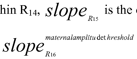
- slope is the current average fetal heart rate waveform within R14
- slope is me current average fetal heart rate waveform profile
- Ri5 and slope is the maternal amplitude threshold average heart rate waveform profile within Ri 6 .
- Figure 1 shows an embodiment according to the present invention for the placement of a sensor in relationship to the fetus and the umbilicus
- Figure 2 shows an embodiment according to the present invention of a plan view of the subject's umbilicus plane
- Figure 3 shows a signal flow for the fetal heart rate determination according to an embodiment of the invention
- Figure 4 shows another signal flow for the fetal heart rate determination according to an embodiment of the invention
- Figure 5 shows another signal flow for the fetal heart rate determination according to an embodiment of the invention.
- Figure 6 shows a fetal heart rate waveform profile according to an embodiment of the present invention.
- the fetal heart rate monitoring system of the invention generally includes at least one sensor mounted on a subject, the sensor being adapted to sense acoustic energy and generates at least one acoustic energy signal. This acoustic energy signal is subsequently received by a processing unit adapted to process the acoustic energy signal and determine at least the average fetal heart rate frequency.
- the processing unit of the invention can be readily employed in conjunction with a multitude of sensors and would be capable of determining a number of parameters.
- Potential applications thus include, for example, the following: fetal tachycardia; fetal bradycardia; saltatory variability; variable decelerations associated with a nonreassuring pattern; and late decelerations with preserved beat-to-beat variability.
- Implementation of the methods and systems of embodiments of the present invention can involve performing or completing selected tasks or steps manually, automatically, or a combination thereof.
- several selected steps could be implemented by hardware or by software on any operating system or any firmware or a combination thereof.
- selected steps of embodiments of the invention could be implemented as a chip or a circuit.
- selected steps of embodiments of the invention could be implemented as a plurality of software instructions being executed by a computer using any suitable operating system.
- selected steps of the method and system of the invention could be described as being performed by a data processor, such as a computing platform for executing a plurality of instructions.
- Figure 1 shows and illustrates a sensor (100) for monitoring the fetal heart rate of a fetus (101).
- the sensor (100) is located proximate to the umbilicus (102) on a subject's body (103).
- Figure 2 illustrates a human subject (203).
- the umbilicus (202) defines a point on an umbilicus axis oriented perpendicular to the length direction of the subject's body (205).
- the umbilicus axis is oriented on an umbilicus plane (204) that is perpendicular to the length of the subject's body.
- the fetal heart rate system comprises at least one sensor mountable on the subject in an area defined by:
- Area ⁇ * (0.05 */ su bject) * (0. 1*w su bject) where /subject is the length (i.e., height) of the subject and w su bject is the width of the subject.
- the width of the subject is equal to the longest chord (206) swept out by the umbilicus plane.
- the resulting area defines an ellipse (207) such that the major axis is perpendicular to the umbilicus axis.
- the lower focus (209) of the area is oriented along the umbilicus axis and the upper focus (208) lies along the direction of the subject's body (205).
- the sensor (100) is adapted to sense acoustic energy and generate at least one acoustic energy signal representing the acoustic energy as depicted in Figure 3.
- a processing unit (309) is adapted to receive the acoustic energy signal (308) with the processing unit (309) being further adapted to process the acoustic energy signal (308).
- the processing unit (309) is capable of determining a number of fetal heart rate parameters (301 -305 , 309). In one embodiment, the processing unit (309) would determine average fetal heart rate frequency as determined by:
- T is the average fetal heart rate frequency
- m is 0 or 1
- n is 0 or 1
- ⁇ is the current fetal heart rate within R 2
- r is the current fetal / maternalamplitu det hreshold
- Ri is a frequency between 50 and 250 Hz and R 2 , R 3 and R4 are independently frequency ranges within which Ri falls. In other embodiments, Ri is a frequency between 80 and 230 Hz and R 2 , R 3 and R 4 are independently frequency ranges within which Ri falls. In further embodiments, Ri is a frequency between 90 and 200 Hz and R 2 , R 3 and R 4 are independently frequency ranges within which Ri falls.
- T is T p and is a time between 10 milliseconds and 28 days. In other embodiments, T is T p and is a time between 12 hours and 14 days. In further embodiments, T is T p and is a time between 5 minutes and 24 hours.
- the fetal heart rate system uses at least one sensor mountable laterally in the same transverse plane as the umbilicus. In one embodiment, at least one sensor is mountable laterally the transverse plane opposite the umbilicus.
- the senor generates a plurality of acoustic energy signals representing the acoustic energy.
- the plurality can be 2, 3, 4, 5, 6 or more acoustic energy signals representing multiple fetal heart rates.
- the processing unit is further adapted to determine a number of additional fetal heart rate parameters such as an average fetal heart rate (303) determined by: average
- T is a time between 10 milliseconds and 28 days. In other embodiments of average fetal heart rate, T is a time between 12 hours and 14 days. In a further embodiment of average fetal heart rate, T is a time between 5 minutes and 24 hours.
- the processing unit is further adapted to determine a number of additional fetal heart rate parameters such as a prolonged rapid heart rate (305) by:
- Ti is a time between 10 milliseconds and 28 days. In other embodiments, Ti is a time between 12 hours and 14 days. In a further embodiment, Ti is a time between 5 minutes and 24 hours.
- the processing unit is further adapted to determine a number of additional fetal heart rate parameters such as a prolonged slow heart rate (304) by:
- T 2 is a time between 10 milliseconds and 28 days. In other embodiments, T 2 is a time between 12 hours and 14 days. In a further embodiment, T 2 is a time between 5 minutes and 24 hours.
- the processing unit is further adapted to determine a number of additional fetal heart rate parameters such as a long-term variability (302) by:
- T 3 is a time between 10 milliseconds and 48 days. In other embodiments, T 3 is a time between 1 second and 60 minutes. In a further embodiment, T 3 is a time between 1 second and 10 minutes. In a further embodiment, T 3 is a time between 1 second and 3 minutes.
- the processing unit is further adapted to determine a number of additional fetal heart rate parameters such as an accelerated heart rate (301) is determined b :
- T 4 is a time between 10 milliseconds and 60 minutes. In other embodiments, T 4 is a time between 1 second and 30 minutes. In a further embodiment, T 4 is a time between 1 second and 3 minutes.
- the processing unit is further adapted to display a variable and sound an alarm.
- the display and alarm can also be an integral component or feature of the processing unit.
- FIG 3 illustrates a processing unit (309) that is configured to activate an alarm (306) or display (307) a message if a condition requires an alert, for example.
- alert conditions include accelerated heart rate (301), long term variability of heart rate (302), fetal heart rate average (303), prolonged slow heart rate (304) and prolonged rapid heart rate (305); however, one of ordinary skill in the art will appreciate that the alert conditions can include one or more of the foregoing.
- the processing unit is adapted to receive and process a plurality of acoustic energy signals and determine at least one average fetal heart rate frequency therefrom. In another embodiment, the processing unit is adapted to receive and process the plurality of acoustic energy signals and determine two average fetal heart rate frequencies as determined by: average I f ⁇ ⁇ ⁇ matemalamplitudethreshold
- (T . ) is the first average fetal heart rate frequency
- ( ⁇ , ) is FHR p l J FHR p i the second average fetal heart rate frequency
- m is 0 or 1
- n is 0 or 1
- m+n is at least 1
- f is the first current fetal heart rate and is within R 2
- f is the second current fetal
- f is the first current fetal heart rate and is within R 3
- f is the maternal the maternal
- Ri is a frequency between 50 and 250 Hz and R 2 , R 3 , R 4 ,
- R 5 , R6 and R 7 are independently frequency ranges within which Ri falls.
- T pl and T p2 are independently times between 10 milliseconds and 28 days. In other embodiments, T pl and T p2 and are independently times between 12 hours and 14 days. In a further embodiment, T pl and T p2 and are independently times between 5 minutes and 24 hours.
- processing unit could be adapted to receive and process the plurality of acoustic energy signals and determine 3, 4, 5, 6 or more average fetal heart rate frequencies.
- a system for monitoring the fetal heart rate of a human subject can be adapted to receive the acoustic energy signal, the processing unit being further adapted to process the acoustic energy signal and determine an aspect average fetal heart rate waveform profile.
- the profile includes a leading edge (601), a trailing edge (603) and a translational edge (602) as determined by:
- Ri is a frequency between 50 and 250 Hz and R 8 , R9 and Rio are independently frequency ranges within which Ri falls.
- T is T p and T p is a time between 10 milliseconds and 28 days.
- FIG 4 illustrates a processing unit (41 1) adapted to receive the acoustic energy signal (410) with the processing unit (41 1) being further adapted to process the acoustic energy signal (410).
- the processing unit (41 1) is capable of determining a number of fetal heart rate parameters (401 and 402).
- processing unit (41 1) could be configured to activate an alarm (408) or display (409) a message if a condition required an alert.
- the processing unit (41 1) can further be adapted to determine a fetal heart rate waveform deviation (401) by:
- slope average (T 5 ) is calculated by
- T 5 is a time between 10 milliseconds and 60 minutes. In other embodiments, T5 is a time between 1 second and 10 minutes. . In yet other embodiments, T5 is a time between 1 second and 3 minutes. In yet other embodiments, T5 is a time between 1 second and 1 minute.
- the processing unit (41 1) can be adapted to receive and process a plurality of acoustic energy signals and determine two fetal heart rate shape profiles (402) as determined from equations by:
- Slope FHR (T p2 ) is the second average fetal heart rate waveform profile, m is 0 or 1 , n is 0 or 1 , m+n is at least 1 , slope R is the first current fetal heart rate waveform profile and is within R 2 , slope R is t e second current fetal heart rate waveform profile and is within R5, slope R is t e first current fetal heart rate waveform profile and is within R3, slope is the second current fetal heart rate waveform profile and is within R ⁇ ,
- Slope is the maternal amplitude threshold frequency and is within R 4 matemalamplitudethreshold
- Ri is a frequency between 50 and 250 Hz and R 2 , R 3 , R 4 , R 5 , and R 7 are independently frequency ranges within which Ri falls.
- T pl and T p2 are independently times between 10
- T pl and T p2 are independently times between 12 hours and 14 days. In further embodiments, T pl and T p2 are
- FIG. 5 illustrates a processing unit (5 1 1 ) adapted to receive the acoustic energy signal (5 10) with the processing unit (5 1 1 ) being further adapted to process the acoustic energy signal (5 10).
- the processing unit (5 1 1 ) is capable of determining a number of fetal heart rate parameters (501 -507).
- processing unit (5 1 1 ) could be configured to activate an alarm (508) or display (509) a message if a condition required an alert.
- accelerated heart rate profile (501 ), long term variability of heart rate profile (502), fetal heart rate average profile (503), fetal heart rate shape profile (504), fetal heart rate profile deviation (505), prolonged slow heart rate profile (506) and prolonged rapid heart rate profile (507), each of which can be determined using methodology similar to that described above with respect to Figures 3 and 4.
- Such conditions have been discussed in "Fetal heart rate patterns: monitoring, interpretation, and management", American College of Obstetricians and Gynecologists technical bulletin no. 207.
- alert conditions can include one or more of the foregoing.
- the displays and alarms of the aforementioned embodiments can also be an integral component or feature of the processing units, separate or remotely located components of the processing units, or any combination thereof.
- a system for monitoring the fetal heart rate of a human subject includes at least one sensor (100) mountable on the subject ( 103) in an area defined by:
- a system for monitoring the heart rate of a fetus in a female human subject includes a processing unit (309) adapted to receive the acoustic energy signal (308).
- the processing unit (309) is further adapted to process the acoustic energy signal (308) and determine the average fetal heart rate frequency as determined by:
- m is 0 or 1
- n is 0 or 1
- J f is the current fetal heart rate within Rn
- J f is the current fetal
- Ri is a frequency between 50 and 250 Hz and Rn, R 12 are independently frequency ranges within which Ri falls.
- T is T p and T p is a time between 0.01 minutes and 28 days.
- a system for monitoring the heart rate of a fetus in a female human subject also includes a processing unit (309) adapted to receive the acoustic energy signal (308), the processing unit (309) being further adapted to process the acoustic energy signal (308) and determine the average fetal heart rate waveform profile as determined by:
- average fetal heart rate waveform wit current average fetal heart rate waveform profile within R 5 and is the maternal amplitude
- Ri is a frequency between 50 and 250 Hz and Ri 4 , R15 and Ri 6 are independently frequency ranges within which Ri falls.
- the frequency of interest is where Ru is equal to Ri 4 .
- the frequency of interest is where R12 is equal to R15.
- the frequency of interest is where R13 is equal to Ri 6 .
- the frequency of interest is where Ru is equal to R M , Ri 2 is equal to R15, R13 is equal to Ri 6 .
- T is T p and T p is a time between 0.01 minutes and 28 days.
- the applications include, without limitation, the ability to monitor fetal heart rate during pregnancy, labor and/or birth; to monitor fetal heart rate waveform profile during pregnancy, labor and/or birth; to monitor fetal heart rate and fetal heart rate waveform profile during pregnancy, labor and/or birth; to monitor fetal heart rate and fetal heart rate waveform profile during pregnancy, labor and/or birth and to detect fetal distress; to monitor fetal heart rate and fetal heart rate waveform profile during pregnancy, labor and/or birth and to detect fetal distress and provide an electrical output; to monitor fetal heart rate and fetal heart rate waveform profile during pregnancy, labor and/or birth and to detect fetal distress and provide an electrical output consisting of an acoustic, visual, mechanical, electrical indicator and combinations thereof; transporting the system to monitor fetal heart rate and fetal heart rate waveform profile during pregnancy, labor and/or birth a distance of at least 5 miles from location A to location B;
Landscapes
- Health & Medical Sciences (AREA)
- Life Sciences & Earth Sciences (AREA)
- Physics & Mathematics (AREA)
- Medical Informatics (AREA)
- Surgery (AREA)
- Veterinary Medicine (AREA)
- Public Health (AREA)
- General Health & Medical Sciences (AREA)
- Animal Behavior & Ethology (AREA)
- Engineering & Computer Science (AREA)
- Biomedical Technology (AREA)
- Heart & Thoracic Surgery (AREA)
- Molecular Biology (AREA)
- Gynecology & Obstetrics (AREA)
- Pathology (AREA)
- Biophysics (AREA)
- Pregnancy & Childbirth (AREA)
- Cardiology (AREA)
- Acoustics & Sound (AREA)
- Physiology (AREA)
- Pediatric Medicine (AREA)
- Reproductive Health (AREA)
- Measuring Pulse, Heart Rate, Blood Pressure Or Blood Flow (AREA)
- Ultra Sonic Daignosis Equipment (AREA)
Abstract
Systems and methods of monitoring the fetal heart rate in a human subject are described. The subject's umbilicus defines a point on an umbilicus axis length perpendicular to the subject's body. The axis is oriented on an umbilicus plane perpendicular to the subject's length. The system includes at least one sensor mountable in an ellipse defined by the subject's length and width. The width is the umbilicus plane's longest chord. The sensor senses acoustic energy and generates a signal. A processing unit receives the signal to determine average fetal heart rate frequency.
Description
Heart Rate Monitor
Field of the Invention The present invention relates to the field of monitoring fetal heart rate.
Background of the Invention
The monitoring and analysis of the heart rate has been a useful technique for diagnosis of cardiac disease for several decades. There are two significant measurements of this signal: the waveform profile and the rate. Both can be useful in clinical diagnoses. During pregnancy, the well-being and condition of a fetus can be assessed by monitoring both properties of the fetal heart rate. For example, the fetal heart rate can often reveal important information for an arrhythmia diagnosis.
Typically, during gestation, the only time a pregnant woman hears her baby's heart beat is during prenatal check-ups. However, women who have experienced miscarriages or complications in previous pregnancies are often more anxious in subsequent pregnancies. Thus, waiting between prenatal appointments for up-dates on their baby's health can be a source of stress to the parents. This need is often
compounded in instances where there are complications with a pregnancy. In such situations, parents may find themselves making frequent trips to the emergency room. Monitoring their baby's heart rate using a fetal heart rate monitor may also help reduce the number of hospital trips that parents have to make. Moreover, fetal heart rate monitors place no stress on the baby so it is safe to use during pregnancy.
Current technology used to follow fetal heart rate is based on Doppler ultrasound. The Doppler device is placed on the maternal abdomen with a coupling gel to find the fetal heart rate. This is typically done by a doctor or ultrasound technician and requires
some degree of training and skill. These types of monitors can be purchased or rented for use as at-home fetal heart rate monitors. Both choices can be fairly expensive.
Summary of the Invention In one aspect, embodiments of the present invention are directed to a system for monitoring the heart rate of a fetus in a female human subject having an umbilicus, the umbilicus defining a point on an umbilicus axis oriented perpendicular to the length of the subject's body, the umbilicus axis oriented on an umbilicus plane that is
perpendicular to the length of the subject's body. The system includes at least one sensor mountable on the subject in an area defined by:
Area = π * (0.05 */subject) * (0. 1 *wsubject) where /subject is the length of the subject and wsubject is the width of the subject. The width of the subject is equal to the longest chord swept out by the umbilicus plane. The area defines an ellipse such that the major axis is perpendicular to the umbilicus axis and the lower focus of the area is oriented along the umbilicus axis. The sensor is adapted to sense acoustic energy and generate at least one acoustic energy signal representing the acoustic energy. A processing unit is adapted to receive the acoustic energy signal, with the processing unit being further adapted to process the acoustic energy signal and determine average fetal heart rate frequency as determined by:
/ average 1 <· / ^ ^ ^ matemalamplitudethreshold \
1 0 where Ri is a frequency between 50 and 250 Hz and R2, R3 and R4 are independently frequency ranges within which Ri falls, T is Tp and is a time between 10
/ average
FHR ^ ) S avera§e fetal neart rate frequency, m is 0 or
1 , n is 0 or 1 , where m+n is at least 1 , f is the current fetal heart rate within R2,
J J f Ri
/ maternalamplitu det hreshold
is the maternal amplitude threshold within R4.
In a further aspect, embodiments the present invention is directed to a system for monitoring the heart rate of a fetus in a female human subject having an umbilicus , the umbilicus defining a point on an umbilicus axis oriented perpendicular to the length of the subject's body, the umbilicus axis oriented on an umbilicus plane that is
perpendicular to the length of the subject's body. The system includes at least one sensor mountable on the subject in an area defined by:
Area = π * (0.05 */subject) * (0. 1 *wsubject) where /subject is the length of the subject and wsubject is the width of the subject. The width of the subject is equal to the longest chord swept out by the umbilicus plane. The area defines an ellipse such that the major axis is perpendicular to the umbilicus axis and the lower focus of said area is oriented along said umbilicus axis. The sensor is adapted to sense acoustic energy and generate at least one acoustic energy signal representing the acoustic energy. A processing unit is adapted to receive the acoustic energy signal, with the processing unit being further adapted to process the acoustic energy signal and determine an aspect average fetal heart rate waveform profile, the profile comprising a leading edge, a trailing edge and a translational edge as determined by: 1
sl°Pe FHR iT^ = j\ [m*sl peR + n*{slopeR -slopeRio τ where Ri is a frequency between 50 and 250 Hz and Rg, R9 and Rio are independently frequency ranges within which Ri falls, T is Tp and Tp is a time between
j average
10 milliseconds and 28 days, slODC (T ) is the slope of the leading edge of the
1 FHR P
average fetal heart rate waveform profile, m is 0 or 1 , n is 0 or 1 , where m+n is at least 1 ,
slope is the current average fetal heart rate waveform profile Rg, slope is the maternalamplitu det hres current average fetal heart rate waveform profile within R9 and SlOpC is the maternal amplitude threshold average heart rate waveform profile within Rio.
In yet a further aspect, embodiments the present invention is directed to a system for monitoring the heart rate of a fetus in a female human subject having an umbilicus , the umbilicus defining a point on an umbilicus axis oriented perpendicular to the length of the subject's body, the umbilicus axis oriented on an umbilicus plane that is perpendicular to the length of the subject's body. The system would includes at least one sensor mountable on said subject in an area defined by:
Area = π * (0.05 */subject) * (0. 1 *wsubject) where /subject is the length of the subject and wsubject is the width of the subject. The width of the subject is equal to the longest chord swept out by the umbilicus plane. The area defines an ellipse oriented such that the major axis is perpendicular to the umbilicus axis and wherein the lower focus of the area is oriented along said umbilicus axis. The sensor is adapted to sense acoustic energy and generate at least one acoustic energy signal representing the acoustic energy. A processing unit adapted to receive said acoustic energy signal, and the processing unit is further adapted to process the acoustic energy signal and determine the average fetal heart rate frequency as determined by:
/ average \ r i ¾ -f ^ matemalamplitudethreshold \
FHR ~ T J \m*J Ru + n Rii J Ra
1 0 where Ri is a frequency between 50 and 250 Hz and Rn, R12 and R13 are
independently frequency ranges within which Ri falls, wherein T is Tp and Tp is a time
/average
is the average fetal heart rate frequency, m is FHR
0 or 1 , n is 0 or 1 , wherein m+n is at least 1 , f is the current fetal heart rate within
J Rn
maternalamplitu det hreshold is the current fetal heart rate within Ri2 and / is the
Rn J Ru
maternal amplitude threshold within R13. The processing unit is also adapted to receive the acoustic energy signal, and is further adapted to process the acoustic energy signal and determine the average fetal heart rate waveform profile as determined by: 1
sl°PeFHR =j\ sloPe Ru +n^sloPe Rl sloPe Rl6 ψ where Ri is a frequency between 50 and 250 Hz and R14, R15 and Ri6 are
independently frequency ranges within which Ri falls, wherein T is Tp and Tp is a time between 0.01 minutes and 28 days, slope is the current average fetal heart rate waveform within R14, slope is me current average fetal heart rate waveform profile
j maternalamplitu det hreshold
within Ri5 and slope is the maternal amplitude threshold average heart rate waveform profile within Ri6.
Brief Description of the Figures
Figure 1 shows an embodiment according to the present invention for the placement of a sensor in relationship to the fetus and the umbilicus; Figure 2 shows an embodiment according to the present invention of a plan view of the subject's umbilicus plane;
Figure 3 shows a signal flow for the fetal heart rate determination according to an embodiment of the invention;
Figure 4 shows another signal flow for the fetal heart rate determination according to an embodiment of the invention;
Figure 5 shows another signal flow for the fetal heart rate determination according to an embodiment of the invention; and
Figure 6 shows a fetal heart rate waveform profile according to an embodiment of the present invention.
Detailed Description of the Invention
As discussed in detail below, the fetal heart rate monitoring system of the invention generally includes at least one sensor mounted on a subject, the sensor being adapted to sense acoustic energy and generates at least one acoustic energy signal. This acoustic energy signal is subsequently received by a processing unit adapted to process the acoustic energy signal and determine at least the average fetal heart rate frequency. As will be appreciated by one having ordinary skill in the art, the processing unit of the invention can be readily employed in conjunction with a multitude of sensors and would be capable of determining a number of parameters. Potential applications thus include, for example, the following: fetal tachycardia; fetal bradycardia; saltatory variability; variable decelerations associated with a nonreassuring pattern; and late decelerations with preserved beat-to-beat variability.
Repeat use of reference characters herein and in the figures is intended to represent same or analogous features or elements of the invention.
It is to be understood that this invention is not limited to particularly exemplified materials, methods or structures as such may, of course, vary. Thus, a number of materials and methods similar or equivalent to those described herein can be used in the practice of the present invention.
It is also to be understood that the terminology used herein is for the purpose of describing particular embodiments of the invention only and is not intended to be limiting.
Unless defined otherwise, all technical and scientific terms used herein have the same meaning as commonly understood by one having ordinary skill in the art to which the invention pertains. Further, all publications, patents and patent applications cited herein, whether supra or infra, are hereby incorporated by reference in their entirety.
As used in this specification and the appended claims, the singular forms "a", "an" and "the" include plural referents unless the content clearly dictates otherwise.
Implementation of the methods and systems of embodiments of the present invention, as described herein, can involve performing or completing selected tasks or steps manually, automatically, or a combination thereof. In some embodiments of the present invention, several selected steps could be implemented by hardware or by software on any operating system or any firmware or a combination thereof. For example, as hardware, selected steps of embodiments of the invention could be implemented as a chip or a circuit. As software, selected steps of embodiments of the invention could be implemented as a plurality of software instructions being executed by a computer using any suitable operating system. In any case, selected steps of the method and system of the invention could be described as being performed by a data processor, such as a computing platform for executing a plurality of instructions.
Reference will now be made in detail to embodiments of the invention, one or more examples of which are illustrated in the accompanying figures.
Figure 1 shows and illustrates a sensor (100) for monitoring the fetal heart rate of a fetus (101). The sensor (100) is located proximate to the umbilicus (102) on a subject's body (103).
Figure 2 illustrates a human subject (203). The umbilicus (202) defines a point on an umbilicus axis oriented perpendicular to the length direction of the subject's body (205). The umbilicus axis is oriented on an umbilicus plane (204) that is perpendicular to the length of the subject's body. The fetal heart rate system comprises at least one sensor mountable on the subject in an area defined by:
Area = π * (0.05 */subject) * (0. 1*wsubject) where /subject is the length (i.e., height) of the subject and wsubject is the width of the subject. The width of the subject is equal to the longest chord (206) swept out by the umbilicus plane. The resulting area defines an ellipse (207) such that the major axis is perpendicular to the umbilicus axis. The lower focus (209) of the area is oriented along the umbilicus axis and the upper focus (208) lies along the direction of the subject's body (205).
The sensor (100) is adapted to sense acoustic energy and generate at least one acoustic energy signal representing the acoustic energy as depicted in Figure 3. A processing unit (309) is adapted to receive the acoustic energy signal (308) with the processing unit (309) being further adapted to process the acoustic energy signal (308). The processing unit (309) is capable of determining a number of fetal heart rate parameters (301 -305 , 309). In one embodiment, the processing unit (309) would determine average fetal heart rate frequency as determined by:
/ average 1 <· / ^ ^ ^ matemalamplitudethreshold \
/ average
(T ) is the average fetal heart rate frequency, m is 0 or 1 , n is 0 or 1 , vv n^ FHR
m+n is at least 1 , ^ is the current fetal heart rate within R2, r is the current fetal
/ maternalamplitu det hreshold
is the maternal amplitude threshold within
R4
In some embodiments, Ri is a frequency between 50 and 250 Hz and R2, R3 and R4 are independently frequency ranges within which Ri falls. In other embodiments, Ri is a frequency between 80 and 230 Hz and R2, R3 and R4 are independently frequency ranges within which Ri falls. In further embodiments, Ri is a frequency between 90 and 200 Hz and R2, R3 and R4 are independently frequency ranges within which Ri falls.
In some embodiments, T is Tp and is a time between 10 milliseconds and 28 days. In other embodiments, T is Tp and is a time between 12 hours and 14 days. In further embodiments, T is Tp and is a time between 5 minutes and 24 hours.
One of skill in the art will appreciate that various sensors can be employed within the scope of the present invention, such as the one disclosed in U.S. Patent No.
6,512,830.
In one embodiment, the fetal heart rate system uses at least one sensor mountable laterally in the same transverse plane as the umbilicus. In one embodiment, at least one sensor is mountable laterally the transverse plane opposite the umbilicus.
In one embodiment, the sensor generates a plurality of acoustic energy signals representing the acoustic energy. The plurality can be 2, 3, 4, 5, 6 or more acoustic energy signals representing multiple fetal heart rates.
In one embodiment, the processing unit is further adapted to determine a number of additional fetal heart rate parameters such as an average fetal heart rate (303) determined by:
average
= f ( V 60
B BPPMM J J F PHHRP
In some embodiments of average fetal heart rate, T is a time between 10 milliseconds and 28 days. In other embodiments of average fetal heart rate, T is a time between 12 hours and 14 days. In a further embodiment of average fetal heart rate, T is a time between 5 minutes and 24 hours.
In one embodiment, the processing unit is further adapted to determine a number of additional fetal heart rate parameters such as a prolonged rapid heart rate (305) by:

FHR V

In some embodiments, Ti is a time between 10 milliseconds and 28 days. In other embodiments, Ti is a time between 12 hours and 14 days. In a further embodiment, Ti is a time between 5 minutes and 24 hours.
In one embodiment, the processing unit is further adapted to determine a number of additional fetal heart rate parameters such as a prolonged slow heart rate (304) by:

FHR 2y
/ average 1 <· / ^ ^ ^ matemalamp litudethreshold \
In some embodiments, T2 is a time between 10 milliseconds and 28 days. In other embodiments, T2 is a time between 12 hours and 14 days. In a further embodiment, T2 is a time between 5 minutes and 24 hours.
In one embodiment, the processing unit is further adapted to determine a number of additional fetal heart rate parameters such as a long-term variability (302) by:
T3
Long tenn variability = ( ^ (Ϊ;) - /, average
FHR
o where faverage(T~) is calculated using:
FHR 3y

In some embodiments, T3 is a time between 10 milliseconds and 48 days. In other embodiments, T3 is a time between 1 second and 60 minutes. In a further embodiment, T3 is a time between 1 second and 10 minutes. In a further embodiment, T3 is a time between 1 second and 3 minutes.
In one embodiment, the processing unit is further adapted to determine a number of additional fetal heart rate parameters such as an accelerated heart rate (301) is determined b :

In other embodiments, the processing unit is further adapted to display a variable and sound an alarm. As will be appreciated by one having ordinary skill in the art, the display and alarm can also be an integral component or feature of the processing unit.
Figure 3 illustrates a processing unit (309) that is configured to activate an alarm (306) or display (307) a message if a condition requires an alert, for example. As illustrated in Figure 3, these alert conditions include accelerated heart rate (301), long term variability of heart rate (302), fetal heart rate average (303), prolonged slow heart rate (304) and prolonged rapid heart rate (305); however, one of ordinary skill in the art will appreciate that the alert conditions can include one or more of the foregoing.
In one embodiment, the processing unit is adapted to receive and process a plurality of acoustic energy signals and determine at least one average fetal heart rate frequency therefrom. In another embodiment, the processing unit is adapted to receive and process the plurality of acoustic energy signals and determine two average fetal heart rate frequencies as determined by: average I f ^ ^ ^ matemalamplitudethreshold
pi 0
and
/ average! 1 s* rmtemalamplitudethreshold
λ ρ2 0 X
/ average ,» average 2
(T . ) is the first average fetal heart rate frequency, (Γ , ) is FHR p l J FHR p i the second average fetal heart rate frequency, m is 0 or 1 , n is 0 or 1 , m+n is at least 1 , f is the first current fetal heart rate and is within R2, f is the second current fetal
J R2 J R5
heart rate and is within R5, f is the first current fetal heart rate and is within R3, f is the maternal the maternal

amplitude threshold frequency within R7. In some embodiments, Ri is a frequency between 50 and 250 Hz and R2, R3, R4,
R5, R6 and R7 are independently frequency ranges within which Ri falls. In some embodiments, Tpl and Tp2 are independently times between 10 milliseconds and 28 days. In other embodiments, Tpl and Tp2 and are independently times between 12 hours and 14 days. In a further embodiment, Tpl and Tp2 and are independently times between 5 minutes and 24 hours.
It is to be understood by one having ordinary skill in the art that the processing unit could be adapted to receive and process the plurality of acoustic energy signals and determine 3, 4, 5, 6 or more average fetal heart rate frequencies.
In one embodiment, a system for monitoring the fetal heart rate of a human subject can be adapted to receive the acoustic energy signal, the processing unit being further adapted to process the acoustic energy signal and determine an aspect average fetal heart rate waveform profile. The profile includes a leading edge (601), a trailing edge (603) and a translational edge (602) as determined by:

rate waveform profile within Rg and slope is me maternal amplitude threshold average heart rate waveform profile within Rio.
In some embodiments, Ri is a frequency between 50 and 250 Hz and R8, R9 and Rio are independently frequency ranges within which Ri falls. In some embodiments, T is Tp and Tp is a time between 10 milliseconds and 28 days.
Figure 4 illustrates a processing unit (41 1) adapted to receive the acoustic energy signal (410) with the processing unit (41 1) being further adapted to process the acoustic energy signal (410). The processing unit (41 1) is capable of determining a number of fetal heart rate parameters (401 and 402). One skilled in the art would also recognize that processing unit (41 1) could be configured to activate an alarm (408) or display (409) a message if a condition required an alert.
In one embodiment, the processing unit (41 1) can further be adapted to determine a fetal heart rate waveform deviation (401) by:

In one embodiment, slopeaverage (T5) is calculated by
FHR

In a further embodiment, T5 is a time between 10 milliseconds and 60 minutes. In other embodiments, T5 is a time between 1 second and 10 minutes. . In yet other embodiments, T5 is a time between 1 second and 3 minutes. In yet other embodiments, T5 is a time between 1 second and 1 minute.
In one embodiment, the processing unit (41 1) can be adapted to receive and process a plurality of acoustic energy signals and determine two fetal heart rate shape profiles (402) as determined from equations by:

and
1 O 9 7 matemalamplitudethreshold slope ^ (TP, ) =—\ [m*slope R + n*{slope R -slopeRm }
0
where SLOVe (T Λ is the first average fetal heart rate waveform profile,
J FHR P
j average 2
Slope FHR (Tp2) is the second average fetal heart rate waveform profile, m is 0 or 1 , n is 0 or 1 , m+n is at least 1 , slope R is the first current fetal heart rate waveform profile and is within R2, slope R is t e second current fetal heart rate waveform profile and is within R5, slope R is t e first current fetal heart rate waveform profile and is within R3, slope is the second current fetal heart rate waveform profile and is within R^,
j matemalamplitudethreshold
Slope is the maternal amplitude threshold frequency and is within R4 matemalamplitudethreshold
and slope is the maternal amplitude threshold frequency within R7.
In one embodiment, Ri is a frequency between 50 and 250 Hz and R2, R3, R4, R5, and R7 are independently frequency ranges within which Ri falls.
In some embodiments, Tpl and Tp2 are independently times between 10
milliseconds and 28 days. In other embodiments, Tpl and Tp2 and are independently times between 12 hours and 14 days. In further embodiments, Tpl and Tp2 are
independently times between 5 minutes and 24 hours.
Figure 5 illustrates a processing unit (5 1 1 ) adapted to receive the acoustic energy signal (5 10) with the processing unit (5 1 1 ) being further adapted to process the acoustic energy signal (5 10). The processing unit (5 1 1 ) is capable of determining a number of fetal heart rate parameters (501 -507). One skilled in the art would also recognize that processing unit (5 1 1 ) could be configured to activate an alarm (508) or display (509) a message if a condition required an alert.
A person or ordinary skill in the art would understand that these conditions could include accelerated heart rate profile (501 ), long term variability of heart rate profile (502), fetal heart rate average profile (503), fetal heart rate shape profile (504), fetal heart rate profile deviation (505), prolonged slow heart rate profile (506) and prolonged rapid heart rate profile (507), each of which can be determined using methodology similar to that described above with respect to Figures 3 and 4. Such conditions have been discussed in "Fetal heart rate patterns: monitoring, interpretation, and management", American College of Obstetricians and Gynecologists technical bulletin no. 207.
Washington, D.C.: ACOG, 1995. One of ordinary skill in the art will appreciate that the alert conditions can include one or more of the foregoing.
As will be appreciated by one having ordinary skill in the art, the displays and alarms of the aforementioned embodiments can also be an integral component or feature of the processing units, separate or remotely located components of the processing units, or any combination thereof.
In one embodiment, a system for monitoring the fetal heart rate of a human subject includes at least one sensor (100) mountable on the subject ( 103) in an area defined by:
Area = π * (0.05 */subject) * (0. 1 *wsubject); and
In another embodiment, a system for monitoring the heart rate of a fetus in a female human subject includes a processing unit (309) adapted to receive the acoustic energy signal (308). In a further embodiment, the processing unit (309) is further adapted to process the acoustic energy signal (308) and determine the average fetal heart rate frequency as determined by:
1 T /
^ average l C I matemalamplitudethreshold fFHR = Ti (™*fRn + n * (fR - fRl3
is the average fetal heart rate frequency, m is 0 or 1 , n is 0 or 1 ,
FHR
m+n is at least 1, J f is the current fetal heart rate within Rn, J f is the current fetal
R Rn
/ maternalamplitu det hreshold
is the maternal amplitude threshold within
In one embodiment, Ri is a frequency between 50 and 250 Hz and Rn, R12 are independently frequency ranges within which Ri falls.
In a further embodiment, T is Tp and Tp is a time between 0.01 minutes and 28 days.
In one embodiment, a system for monitoring the heart rate of a fetus in a female human subject also includes a processing unit (309) adapted to receive the acoustic energy signal (308), the processing unit (309) being further adapted to process the acoustic energy signal (308) and determine the average fetal heart rate waveform profile as determined by:
-j average 1 f 7 7 7 matemalamplitudethreshold \ sl°Pe PHR =T) (m*stopeRi + n*{slopeRi5-slopeRi6 τ

Ru
average fetal heart rate waveform wit current average fetal heart rate waveform profile within R 5 and is the maternal amplitude
threshold average heart rate waveform profile within Ri6.
In one embodiment, Ri is a frequency between 50 and 250 Hz and Ri4, R15 and Ri6 are independently frequency ranges within which Ri falls. In one embodiment, the frequency of interest is where Ru is equal to Ri4. In another embodiment, the frequency of interest is where R12 is equal to R15. In another embodiment, the frequency of interest is where R13 is equal to Ri6. In a further embodiment, the frequency of interest is where Ru is equal to RM, Ri2 is equal to R15, R13 is equal to Ri6.
In yet a further embodiment, T is Tp and Tp is a time between 0.01 minutes and 28 days.
Method and system embodiments of the present invention can thus be effectively employed in numerous applications. The applications include, without limitation, the ability to monitor fetal heart rate during pregnancy, labor and/or birth; to monitor fetal heart rate waveform profile during pregnancy, labor and/or birth; to monitor fetal heart rate and fetal heart rate waveform profile during pregnancy, labor and/or birth; to monitor fetal heart rate and fetal heart rate waveform profile during pregnancy, labor and/or birth and to detect fetal distress; to monitor fetal heart rate and fetal heart rate waveform profile during pregnancy, labor and/or birth and to detect fetal distress and provide an electrical output; to monitor fetal heart rate and fetal heart rate waveform profile during pregnancy, labor and/or birth and to detect fetal distress and provide an electrical output consisting of an acoustic, visual, mechanical, electrical indicator and combinations thereof; transporting the system to monitor fetal heart rate and fetal heart rate waveform profile during pregnancy, labor and/or birth a distance of at least 5 miles from location A
to location B; transporting the system to monitor fetal heart rate and fetal heart rate waveform profile during pregnancy, labor and/or birth a distance of at least 5 miles from location A to location B by driving across land, sailing across water and/or flying through air; transporting the system to monitor fetal heart rate and fetal heart rate waveform profile during pregnancy, labor and/or birth a distance of at least 5 miles from location A to location B where A and B are in different countries.
Although specific embodiments of the present invention are herein illustrated and described in detail, the invention is not limited thereto. The above detailed descriptions are provided as exemplary of the present invention and should not be construed as constituting any limitation of the invention. Modifications will be obvious to those skilled in the art, and all modifications that do not depart from the spirit of the invention are intended to be included with the scope of the appended claims.
Claims
1. A system for monitoring the heart rate of a fetus in a female human subject having an umbilicus , the umbilicus defining a point on an umbilicus axis oriented perpendicular to the length of the subject's body, the umbilicus axis oriented on an umbilicus plane that is perpendicular to the length of the subject's body, comprising:
at least one sensor mountable on said subject in an area defined by equation (1); Area = π * (0.05*/subject) * (0.1 *wsubject) (1) wherein /subject is the length of the subject and wSUbject is the width of the subject, wherein the width of the subject is equal to the longest chord swept out by the umbilicus plane, said area defining an ellipse such that the major axis is perpendicular to the umbilicus axis and wherein the lower focus of said area is oriented along said umbilicus axis; and
said sensor being adapted to sense acoustic energy and generate at least one acoustic energy signal representing said acoustic energy; and
a processing unit adapted to receive said acoustic energy signal, said processing unit being further adapted to process said acoustic energy signal and determine average fetal heart rate frequency as determined by equation (2);
/

/ average
(T ) is the average fetal heart rate FHR
frequency, m is 0 or 1 , n is 0 or 1 , wherein m+n is at least \ ,† ^ is the current fetal heart rate within R2, is
J f the current fetal heart rate within R3 and
R3
matemalamplitu det hreshold
j is the maternal amplitude threshold within R4.
2. The system of Claim 1 , wherein said processing unit is further adapted to determine an average fetal heart rate by equation (3);
average
average (Γ ) * 60 (3).
BBPPMM J FHR
3. The system of Claim 1, wherein said processing unit is further adapted to determine a prolonged rapid heart rate by equation (4); f (fZr<JP)-fZrV ) dTx (4)
0 wherein f^age( ^) is calculated using equation (2) wherein T is Tls and Ti is a time between 10 milliseconds and 28 days.
4. The system of Claim 1 , wherein said processing unit is further adapted to
determine a prolonged slow heart rate by equation (5);

5. The system of Claim 1 , wherein said processing unit is further adapted to
determine a long term variability by equation (6); Long term variability f;-ge( (6) 
wherein f average [s calculated using equation (2) wherein T is T3 and T3 is a
FHR 3 '
time between 10 milliseconds and 48 days.
6. The system of Claim 1 , wherein acceleration is determined by equation (7); 
wherein fp^™ge(J"^) is calculated using equation (2) wherein T is T4 and T4 is a time between 10 milliseconds and 60 minutes.
7. The system of Claim 3, wherein Ti is between 12 hours and 14 days.
8. The system of Claims 3, wherein Ti is between 5 minutes and 24 hours.
9. The system of Claims 4, wherein T2 12 hours and 28 days.
10. The system of Claims 4, wherein T2 is between 5 minutes and 24 hours.
1 1. The system of Claim 5, wherein T3 is between 1 second and 60 minutes.
12. The system of Claim 5, wherein T3 is between 1 second and 10 minutes.
13. The system of Claim 5, wherein T3 is between 1 second and 3 minutes.
14. The system of Claim 6, wherein T4 is between 1 second and 30 minutes.
15. The system of Claim 5, wherein T4 is between 1 second and 3 minutes.
16. The system of Claim 1, wherein said at least one sensor is mountable laterally in the same transverse plane as the umbilicus.
17. The system of Claim 1, wherein said at least one sensor is mountable laterally in the same transverse plane opposite the umbilicus.
18. The system of Claim 1, wherein said sensor generates a plurality of acoustic energy signals representing said acoustic energy.
19. The system of Claim 18, wherein said processing unit is adapted to receive and process said plurality of acoustic energy signals and determine at least one average fetal heart rate frequency rate therefrom.
20. The system of Claim 18, wherein said processing unit is adapted to receive and process said plurality of acoustic energy signals and determine two average fetal heart rate frequencies as determined from equations (2) and (8); 1 Γ2
/ average*! (· / s*n maternalamplitudethreshold
™ <T \ -*ίί + »·υϊ-Λ, > wherein Ri is a frequency between 50 and 250 Hz and R2, R3, R4, R5, R6 and R7 are inde endently frequency ranges within which Ri falls, wherein T is Tp and T2 is Tp2,
rt is  aternal
maternal amplitude threshold frequency within R7.
21. A system for monitoring the heart rate of a fetus in a female human subject having an umbilicus , the umbilicus defining a point on an umbilicus axis oriented perpendicular to the length of the subject's body, the umbilicus axis oriented on an umbilicus plane that is perpendicular to the length of the subject's body, comprising: at least one sensor mountable on said subject in an area defined by equation (9);
Area = π * (0.05 */subject) * (0. 1 *wsubject) (9) wherein /subject is the length of the subject and wSUbject is the width of the subject, wherein the width of the subject is equal to the longest chord swept out by the umbilicus plane, said area defining an ellipse such that the major axis is perpendicular to the umbilicus axis and wherein the lower focus of said area is oriented along said umbilicus axis; and
said sensor being adapted to sense acoustic energy and generate at least one acoustic energy signal representing said acoustic energy; and
a processing unit adapted to receive said acoustic energy signal, said processing unit being further adapted to process said acoustic energy signal and determine an aspect average fetal heart rate waveform profile, said profile comprising a leading edge, a trailing edge and a translational edge as determined by equation ( 10);
11 T f / , 7 7 7 matemalamplitudethreshold \ \ / -ι slope ^ (T ) = - \ [m*slopeR + n * {slope R - slope Rm } k/r (i0)
wherein Ri is a frequency between 50 and 250 Hz and Rg, R9 and Rio are independently frequency ranges within which Ri falls, wherein T is Tp and Tp is a j average
time between 10 milliseconds and 28 days, slope FHR (Tp ) is the slope of the leading edge of the average fetal heart rate waveform profile, m is 0 or 1 , n is 0 or 1 , wherein m+n is at least 1 , slope is me current average fetal heart rate waveform profile Rs, slope is me current average fetal heart rate waveform profile within
maternalamplitu det hreshold
Rg and SlOpC is me maternal amplitude threshold average heart rate waveform profile within Rio.
22. The system of Claim 21 , wherein said processing unit is further adapted to determine a fetal heart rate wave form deviation is determined by equation (1 1);

23. The system of Claim 21 , wherein Tp is between 1 second and 10 minutes.
24. The system of Claim 21 , wherein Tp is between 1 second and 3 minutes.
25. The system of Claim 21 , wherein Tp is between 1 second and 1 minute.
26. The system of Claim 21 , wherein said sensor generates a plurality of acoustic energy signals representing said acoustic energy.
27. The system of Claim 26, wherein said processing unit is adapted to receive and process said plurality of acoustic energy signals and determine at least one fetal heart rate shape profile therefrom.
28. The system of Claim 26, wherein said processing unit is adapted to receive and process said plurality of acoustic energy signals and determine two fetal heart rate shape profiles as determined from equations (10) and (12);
T 2
7 average! , \ /· o τ matemalamplitudethreshold \ , ,Λ slope FHR (T 2 ) = Tj j (aslope2 R + * {slope2 R9 - slope R o π )
0 wherein Ri is a frequency between 50 and 250 Hz and R2, R3, R4, R5, R6 and R7 are independently frequency ranges within which Ri falls, wherein T is Tp and T2 is Tp2, Tp and Tp2 are independent times between 10 milliseconds and 28 days,
j average
SlOPe (ΤΌ 2 ) is the first average fetal heart rate waveform profile,
J FHR P
j average 2
SlOPC (T 2) is the second average fetal heart rate waveform profile, m is 0 or
1 FHR
1 , n is 0 or 1 , wherein m+n is at least 1 , slope R is me first current fetal heart rate waveform profile and is within R2, slop R is the second current fetal heart rate waveform profile and is within R5, slope R is the first current fetal heart rate waveform profile and is within R3, slop R is the second current fetal heart rate
j matemalamplitudethreshold
waveform profile and is within R^, slopCR is the maternal amplitude
j matemalamplitudethreshold
threshold frequency and is within R4 and slopCR is the maternal amplitude threshold frequency within R7.
29. A system for monitoring the heart rate of a fetus in a female human subject having an umbilicus , the umbilicus defining a point on an umbilicus axis oriented perpendicular to the length of the subject's body, the umbilicus axis oriented on an umbilicus plane that is perpendicular to the length of the subject's body, comprising: at least one sensor mountable on said subject in an area defined by equation (13); Area = π * (0.05*/subject) * (0.1 *wsubject) (13) wherein /subject is the length of the subject and wsubject is the width of the subject, wherein the width of the subject is equal to the longest chord swept out by the umbilicus plane, said area defining an ellipse oriented such that the major axis is perpendicular to the umbilicus axis and wherein the lower focus of said area is oriented along said umbilicus axis; and
said sensor being adapted to sense acoustic energy and generate at least one acoustic energy signal representing said acoustic energy; and
a processing unit adapted to receive said acoustic energy signal, said processing unit being further adapted to process said acoustic energy signal and determine the average fetal heart rate frequency as determined by equation 14;
/

/average
is the average fetal heart rate FHR
frequency, m is 0 or 1 , n is 0 or 1 , wherein m+n is at least 1 , f is the current
J R fetal heart rate within Ru, f is the current fetal heart rate within Ri2 and
J Ru
/ matemalamp litu det hreshold
is the maternal amplitude threshold within Ri3; and
Ru
a processing unit adapted to receive said acoustic energy signal, said processing unit being further adapted to process said acoustic energy signal and determine the average fetal heart rate waveform profile as determined by equation (15); j average
sl°PeFHR =


amplitude threshold average heart rate waveform profile within Ri6.
30. The system of Claim 29, wherein Ru is equal to Ri4.
3 1 . The system of Claim 29, wherein Ri2 is equal to R15.
32. The system of Claim 29, wherein R13 is equal to Ri6.
33. The system of Claim 29, wherein Ru is equal to Ri4, Ri2 is equal to R15, R13 is equal to Ri6.
34. A method for monitoring the heart rate of a fetus in a female human subject having an umbilicus , the umbilicus defining a point on an umbilicus axis oriented perpendicular to the length of the subject's body, the umbilicus axis oriented on an umbilicus plane that is perpendicular to the length of the subject's body, comprising:
mounting at least one sensor on said subject in an area defined by equation (16);
Area = π * (0.05 */subject) * (0. 1 *wsubject) ( 16) wherein /subject is the length of the subject and wsubject is the width of the subject, wherein the width of the subject is equal to the longest chord swept out by the umbilicus plane, said area defining an ellipse such that the major axis is perpendicular to the umbilicus axis and wherein the lower focus of said area is oriented along said umbilicus axis;
sensing an acoustic energy;
generating at least one acoustic energy signal representing said acoustic energy; processing said acoustic energy signal; and
determining an average fetal heart rate frequency as determined by equation (17);
T
/ average \ f / maternalarnplitudetrrreshold \
™ (T T 1 S 0 V "·« *- Λ Ψ (17) wherein Ri is a frequency between 50 and 250 Hz and R2, R3 and R4 are independently frequency ranges within which Ri falls, wherein T is Tp and Tp is a time
/ average
(T ) is the average fetal heart rate FHR p
frequency, m is 0 or 1, n is 0 or 1, wherein m+n is at least 1,† ^ is the current fetal heart rate within R2, f is the current fetal heart rate within R3 and
J Ri
/ maternalamplitu det hreshold
is the maternal amplitude threshold within R4.
35. A method for monitoring the heart rate of a fetus in a female human subject having an umbilicus , the umbilicus defining a point on an umbilicus axis oriented perpendicular to the length of the subject's body, the umbilicus axis oriented on an umbilicus plane that is perpendicular to the length of the subject's body, comprising: mounting at least one sensor on said subject in an area defined by equation (18);
Area = π * (0.05*/subject) * (0.1 *wsubject) (18) wherein /subject is the length of the subject and wSUbject is the width of the subject, wherein the width of the subject is equal to the longest chord swept out by the umbilicus plane, said area defining an ellipse such that the major axis is perpendicular to the umbilicus axis and wherein the lower focus of said area is oriented along said umbilicus axis;
sensing an acoustic energy;
generating at least one acoustic energy signal representing said acoustic energy; and
processing said acoustic energy signal; and
determining an aspect average fetal heart rate waveform profile, said profile comprising a leading edge, a trailing edge and a translational edge as determined by equation 19; 1
slope ^ (T) = -j(m*slopeR + n*{slopeR9-slopeRio (19)
0 wherein Ri is a frequency between 50 and 250 Hz and Rg, R9 and Rio are independently frequency ranges within which Ri falls, wherein T is Tp and Tp is a time
j average
between 10 milliseconds and 28 days, SIOO6 (T ) is the slope of the leading edge
1 FHR
of the average fetal heart rate waveform profile, m is 0 or 1 , n is 0 or 1 , wherein m+n is at least 1 , slope is the current average fetal heart rate waveform within R8, slope is the current average fetal heart rate waveform profile within R9 and
j maternalamplitu det hreshold
Slope is the maternal amplitude threshold average heart rate waveform profile within R 10·
36. A method for monitoring the heart rate of a fetus in a female human subject having an umbilicus , the umbilicus defining a point on an umbilicus axis oriented perpendicular to the length of the subject's body, the umbilicus axis oriented on an umbilicus plane that is perpendicular to the length of the subject's body, comprising: mounting at least one sensor on said subject in an area defined by equation (20); Area = π * (0.05*/subject) * (0.1 *wsubject) (20) wherein /subject is the length of the subject and wsubject is the width of the subject, wherein the width of the subject is equal to the longest chord swept out by the umbilicus plane, said area defining an ellipse such that the major axis is perpendicular to the umbilicus axis and wherein the lower focus of said area is oriented along said umbilicus axis;
sensing an acoustic energy;
generating at least one acoustic energy signal representing said acoustic energy; and
processing said acoustic energy signal;
determining an average fetal heart rate frequency as determined by equation (21); 
wherein Ri is a frequency between 50 and 250 Hz and Ru, R12, R13, R14, Ris and Ri6 are independently frequency ranges within which Ri falls, T is Tp and Tp is a
/ average
(T ) is the average fetal heart FHR P
rate frequency, m is 0 or 1 , n is 0 or 1 , wherein m+n is at least 1 , f is the current
J R fetal heart rate within Ru, f is the current fetal heart rate within R12 and
J Rn
/ maternalamplitu det hreshold
is the maternal amplitude threshold within R13;
R\l
determining an aspect average fetal heart rate waveform profile, said profile comprising a leading edge, a trailing edge and a translational edge as determined by equation (22); matemalamplitudethreshold.


maternal amplitude threshold average heart rate waveform profile within Rio.
37. The method of Claims 34, 35 or 36, wherein said fetal heart rate frequency comprises an event associated with a fetal heart rate, said fetal heart rate being selected from the group consisting of baseline beats per minute, prolonged rapid heart rate, prolonged slow heart rate, transients and constant variation from the baseline.
38. The method of Claim 37, wherein said processing unit is further adapted to detect fetal distress, and upon detection of said fetal distress provides an electrical output.
39. The method of Claim 38, wherein said electrical output is a human sensible output, said human sensible output consisting of an acoustic, visual, mechanical, electrical indicator and combinations thereof.
40. A method for transporting the processing system of any of Claims 1-29, said method comprising moving the system a distance of at least 5 miles from location A to location B.
41. The method of Claim 40, wherein said moving comprises at least one mode of transportation from the group consisting of driving across land, sailing across water and flying through air.
42. The method of Claim 40, wherein location A is in one country and location B is in another country.
Priority Applications (2)
| Application Number | Priority Date | Filing Date | Title |
|---|---|---|---|
| JP2012537992A JP2013509956A (en) | 2009-11-04 | 2010-11-04 | Heart rate monitor |
| EP10829089.1A EP2496143A4 (en) | 2009-11-04 | 2010-11-04 | Heart rate monitor |
Applications Claiming Priority (2)
| Application Number | Priority Date | Filing Date | Title |
|---|---|---|---|
| US25800809P | 2009-11-04 | 2009-11-04 | |
| US61/258,008 | 2009-11-04 |
Publications (1)
| Publication Number | Publication Date |
|---|---|
| WO2011056974A1 true WO2011056974A1 (en) | 2011-05-12 |
Family
ID=43970331
Family Applications (1)
| Application Number | Title | Priority Date | Filing Date |
|---|---|---|---|
| PCT/US2010/055450 Ceased WO2011056974A1 (en) | 2009-11-04 | 2010-11-04 | Heart rate monitor |
Country Status (3)
| Country | Link |
|---|---|
| EP (1) | EP2496143A4 (en) |
| JP (1) | JP2013509956A (en) |
| WO (1) | WO2011056974A1 (en) |
Cited By (1)
| Publication number | Priority date | Publication date | Assignee | Title |
|---|---|---|---|---|
| CN111481230A (en) * | 2019-01-28 | 2020-08-04 | 深圳市理邦精密仪器股份有限公司 | Processing method and device of fetal monitoring signal, fetal monitoring device and medium |
Citations (5)
| Publication number | Priority date | Publication date | Assignee | Title |
|---|---|---|---|---|
| US5088497A (en) * | 1987-02-03 | 1992-02-18 | Terumo Kabushiki Kaisha | Fetus monitoring apparatus |
| US5724032A (en) * | 1995-07-01 | 1998-03-03 | Hewlett-Packard Company | Method and apparatus for compressing and displaying digital data, particularly the heart rate of fetal monitors |
| US6512830B1 (en) | 1995-02-09 | 2003-01-28 | Meditron As | Auscultation apparatus |
| US20050124878A1 (en) * | 2001-07-02 | 2005-06-09 | Reuven Sharony | Methods and apparatus for objective fetal diagnosis |
| US20070260133A1 (en) * | 2006-05-08 | 2007-11-08 | Tycohealthcare Group Lp | Radial electrode array |
Family Cites Families (15)
| Publication number | Priority date | Publication date | Assignee | Title |
|---|---|---|---|---|
| JPS5641432Y2 (en) * | 1975-09-11 | 1981-09-28 | ||
| JPS5722736A (en) * | 1980-07-17 | 1982-02-05 | Terumo Corp | Cycle measuring system |
| JPS5822029A (en) * | 1981-07-31 | 1983-02-09 | テルモ株式会社 | Cycle measuring system |
| JPS5822108U (en) * | 1982-06-27 | 1983-02-10 | 幸栄電子工業株式会社 | Fetal heart rate automatic analysis device |
| CA1244135A (en) * | 1984-10-15 | 1988-11-01 | Harold M Hastings | External fetal heart monitor |
| US4781200A (en) * | 1985-10-04 | 1988-11-01 | Baker Donald A | Ambulatory non-invasive automatic fetal monitoring system |
| JP2792386B2 (en) * | 1993-04-15 | 1998-09-03 | 松下電器産業株式会社 | Biological information processing device |
| US5596993A (en) * | 1994-09-21 | 1997-01-28 | Beth Israel Hospital | Fetal data processing system and method |
| US5524631A (en) * | 1994-10-13 | 1996-06-11 | The United States Of America As Represented By The Administrator Of The National Aeronautics And Space Administration | Passive fetal heart rate monitoring apparatus and method with enhanced fetal heart beat discrimination |
| ATE237988T1 (en) * | 1994-11-24 | 2003-05-15 | Inst Of Respiratory Medicine L | DEVICE FOR BIO-PHYSICAL MONITORING OF A FETU |
| JPH08154908A (en) * | 1994-12-05 | 1996-06-18 | Casio Comput Co Ltd | Biological information measuring device |
| DE69530427T2 (en) * | 1995-08-10 | 2004-03-04 | Pentavox Kft. | DEVICE FOR MEASURING THE FETAL HEART RATE |
| US6551251B2 (en) * | 2000-02-14 | 2003-04-22 | The United States Of America As Represented By The Administrator Of The National Aeronautics And Space Administration | Passive fetal heart monitoring system |
| JP2006288620A (en) * | 2005-04-08 | 2006-10-26 | Ntt Docomo Inc | Mobile device |
| AU2007248156B2 (en) * | 2006-05-02 | 2011-05-26 | Lono Medical Systems, Llc | Passive phonography heart monitor |
-
2010
- 2010-11-04 EP EP10829089.1A patent/EP2496143A4/en not_active Withdrawn
- 2010-11-04 WO PCT/US2010/055450 patent/WO2011056974A1/en not_active Ceased
- 2010-11-04 JP JP2012537992A patent/JP2013509956A/en active Pending
Patent Citations (5)
| Publication number | Priority date | Publication date | Assignee | Title |
|---|---|---|---|---|
| US5088497A (en) * | 1987-02-03 | 1992-02-18 | Terumo Kabushiki Kaisha | Fetus monitoring apparatus |
| US6512830B1 (en) | 1995-02-09 | 2003-01-28 | Meditron As | Auscultation apparatus |
| US5724032A (en) * | 1995-07-01 | 1998-03-03 | Hewlett-Packard Company | Method and apparatus for compressing and displaying digital data, particularly the heart rate of fetal monitors |
| US20050124878A1 (en) * | 2001-07-02 | 2005-06-09 | Reuven Sharony | Methods and apparatus for objective fetal diagnosis |
| US20070260133A1 (en) * | 2006-05-08 | 2007-11-08 | Tycohealthcare Group Lp | Radial electrode array |
Non-Patent Citations (1)
| Title |
|---|
| See also references of EP2496143A4 * |
Cited By (2)
| Publication number | Priority date | Publication date | Assignee | Title |
|---|---|---|---|---|
| CN111481230A (en) * | 2019-01-28 | 2020-08-04 | 深圳市理邦精密仪器股份有限公司 | Processing method and device of fetal monitoring signal, fetal monitoring device and medium |
| CN111481230B (en) * | 2019-01-28 | 2023-06-09 | 深圳市理邦精密仪器股份有限公司 | Fetal monitoring signal processing method and device, fetal monitoring device and medium |
Also Published As
| Publication number | Publication date |
|---|---|
| EP2496143A4 (en) | 2014-08-20 |
| JP2013509956A (en) | 2013-03-21 |
| EP2496143A1 (en) | 2012-09-12 |
Similar Documents
| Publication | Publication Date | Title |
|---|---|---|
| EP1680018B1 (en) | Fetal surveillance | |
| CN102458259B (en) | Utilize the method and apparatus of the anatomical structure of ultrasonic identification movement | |
| Kennedy et al. | A radiologist’s guide to the performance and interpretation of obstetric doppler US | |
| US20150150538A1 (en) | Method for improved determination of maternal heart rate and fetal monitoring system thereto | |
| Toi et al. | Ultrasonically evident fetal nuchal skin thickening: is it specific for Down syndrome? | |
| CN102485180B (en) | Fetus monitoring device and method | |
| Gerson et al. | Duplex Doppler ultrasound in the evaluation of growth in twin pregnancies | |
| EP2496143A1 (en) | Heart rate monitor | |
| Wahyuni et al. | Early detection model of normal and abnormal blood flow using pulse Oximetry non-invasive of pregnant heart rate | |
| Akiyama et al. | Comparison of alterations in fetal regional arterial vascular resistance in appropriate-for-gestational-age singleton, twin and triplet pregnancies | |
| Malhotra et al. | Antenatal assessment of fetal well-being | |
| Witter et al. | The effect of maternal position on uterine artery flow during antepartum fetal heart rate testing | |
| RU2193344C2 (en) | Method for evaluating functional state of fetus | |
| EP2906104B1 (en) | System and method for breathing rate measurements | |
| Kribèche et al. | Detection and analysis of fetal movements by ultrasonic multi-sensor Doppler (ACTIFOETUS) | |
| Sezik et al. | EP01. 01: Reliability of cavum septum pellucidum volume measurements during second trimester ultrasonography in structurally normal fetuses | |
| Iliescu et al. | EP01. 02: Abnormal cavum septi pellucidi (CSP): experience of a tertiary centre | |
| Chourasia et al. | Prenatal Detection of Congenital Heart Defects: Study & Comparative Analysis of Existing Techniques | |
| RU2006109577A (en) | METHOD FOR DIAGNOSTIC DISTURBANCES OF INNO-UTERINE STATE OF THE FETUS AND DEVICE FOR ITS IMPLEMENTATION | |
| Desai et al. | Correlations of fetal cardiac sympathetic activity with maternal body mass index | |
| Prasanthi et al. | Evaluation of Arterial and Venous System Doppler in Growth Restricted Fetus | |
| JP2005205212A (en) | Method and system for determining blood flow characteristic of small infant | |
| LaMontagne et al. | Development and implementation of a nutritional-risk screening procedure for pregnant mothers in a Honduran community hospital system | |
| Farine et al. | New technologies for monitoring labor progress | |
| RU2568254C2 (en) | Device for control and prediction of condition of "mother-foetus" system in procces of obstetric aid |
Legal Events
| Date | Code | Title | Description |
|---|---|---|---|
| 121 | Ep: the epo has been informed by wipo that ep was designated in this application |
Ref document number: 10829089 Country of ref document: EP Kind code of ref document: A1 |
|
| WWE | Wipo information: entry into national phase |
Ref document number: 2012537992 Country of ref document: JP |
|
| NENP | Non-entry into the national phase |
Ref country code: DE |
|
| WWE | Wipo information: entry into national phase |
Ref document number: 2010829089 Country of ref document: EP |