WO2011067809A1 - データ通信ネットワークシステム - Google Patents
データ通信ネットワークシステム Download PDFInfo
- Publication number
- WO2011067809A1 WO2011067809A1 PCT/JP2009/006536 JP2009006536W WO2011067809A1 WO 2011067809 A1 WO2011067809 A1 WO 2011067809A1 JP 2009006536 W JP2009006536 W JP 2009006536W WO 2011067809 A1 WO2011067809 A1 WO 2011067809A1
- Authority
- WO
- WIPO (PCT)
- Prior art keywords
- communication
- ecu
- node
- network
- network system
- Prior art date
- Legal status (The legal status is an assumption and is not a legal conclusion. Google has not performed a legal analysis and makes no representation as to the accuracy of the status listed.)
- Ceased
Links
Images


Classifications
-
- H—ELECTRICITY
- H04—ELECTRIC COMMUNICATION TECHNIQUE
- H04L—TRANSMISSION OF DIGITAL INFORMATION, e.g. TELEGRAPHIC COMMUNICATION
- H04L12/00—Data switching networks
- H04L12/28—Data switching networks characterised by path configuration, e.g. LAN [Local Area Networks] or WAN [Wide Area Networks]
- H04L12/40—Bus networks
- H04L12/407—Bus networks with decentralised control
- H04L12/417—Bus networks with decentralised control with deterministic access, e.g. token passing
-
- H—ELECTRICITY
- H04—ELECTRIC COMMUNICATION TECHNIQUE
- H04J—MULTIPLEX COMMUNICATION
- H04J3/00—Time-division multiplex systems
- H04J3/02—Details
- H04J3/06—Synchronising arrangements
- H04J3/0635—Clock or time synchronisation in a network
- H04J3/0638—Clock or time synchronisation among nodes; Internode synchronisation
- H04J3/0652—Synchronisation among time division multiple access [TDMA] nodes, e.g. time triggered protocol [TTP]
-
- H—ELECTRICITY
- H04—ELECTRIC COMMUNICATION TECHNIQUE
- H04L—TRANSMISSION OF DIGITAL INFORMATION, e.g. TELEGRAPHIC COMMUNICATION
- H04L12/00—Data switching networks
- H04L12/28—Data switching networks characterised by path configuration, e.g. LAN [Local Area Networks] or WAN [Wide Area Networks]
- H04L12/40—Bus networks
- H04L12/40006—Architecture of a communication node
- H04L12/40026—Details regarding a bus guardian
-
- H—ELECTRICITY
- H04—ELECTRIC COMMUNICATION TECHNIQUE
- H04L—TRANSMISSION OF DIGITAL INFORMATION, e.g. TELEGRAPHIC COMMUNICATION
- H04L12/00—Data switching networks
- H04L12/28—Data switching networks characterised by path configuration, e.g. LAN [Local Area Networks] or WAN [Wide Area Networks]
- H04L12/46—Interconnection of networks
- H04L12/4604—LAN interconnection over a backbone network, e.g. Internet, Frame Relay
- H04L12/462—LAN interconnection over a bridge based backbone
- H04L12/4625—Single bridge functionality, e.g. connection of two networks over a single bridge
-
- H—ELECTRICITY
- H04—ELECTRIC COMMUNICATION TECHNIQUE
- H04L—TRANSMISSION OF DIGITAL INFORMATION, e.g. TELEGRAPHIC COMMUNICATION
- H04L12/00—Data switching networks
- H04L12/28—Data switching networks characterised by path configuration, e.g. LAN [Local Area Networks] or WAN [Wide Area Networks]
- H04L12/40—Bus networks
- H04L2012/40208—Bus networks characterized by the use of a particular bus standard
- H04L2012/40241—Flexray
-
- H—ELECTRICITY
- H04—ELECTRIC COMMUNICATION TECHNIQUE
- H04L—TRANSMISSION OF DIGITAL INFORMATION, e.g. TELEGRAPHIC COMMUNICATION
- H04L12/00—Data switching networks
- H04L12/28—Data switching networks characterised by path configuration, e.g. LAN [Local Area Networks] or WAN [Wide Area Networks]
- H04L12/40—Bus networks
- H04L2012/40267—Bus for use in transportation systems
- H04L2012/40273—Bus for use in transportation systems the transportation system being a vehicle
Definitions
- the present invention relates to a data communication network system.
- a data communication network system that transmits and receives frames between a plurality of terminals via a transmission line.
- communication networking is progressing with an increase in electronic control units (ECUs) mounted on the vehicles.
- ECUs electronice control units
- CAN Controller Area network
- LIN Local Interconnect Network
- the control method disclosed in Patent Document 1 includes a time measurement unit in each communication control unit in an in-vehicle LAN in which a plurality of communication control units are connected by an in-vehicle LAN network. And the control method currently indicated by the above-mentioned patent documents 1 makes synchronous communication data transmit to one communication control unit connected to the above-mentioned in-vehicle LAN network, and each communication control unit is accompanied with reception of this synchronous data.
- the time measuring means is synchronized.
- the present invention has been made in view of the above circumstances, and an object of the present invention is to provide a data communication network system in which a desired unit can determine the starting point of a communication transmission schedule.
- the first aspect of the present invention is a data communication network system in which a plurality of electronic control units perform network communication according to a time trigger type communication protocol via a communication line.
- the data communication network system includes control means for setting the communication line in a communication prohibited state in advance and releasing the communication prohibited state at a predetermined timing. Further, one predetermined unit among the plurality of electronic control units transmits a synchronization alignment message for adjusting communication timing with other units immediately after the communication prohibited state is released.
- the network communication is connected to another network communication via a gateway, and the control means is a transmission / reception regulated by the other network communication.
- the communication prohibited state is canceled based on the period.
- control unit sets the communication line to a communication prohibited state when the plurality of electronic control units finish communication. .
- control means sets the communication prohibited state by applying a predetermined voltage to the communication line.
- the fifth aspect of the present invention is characterized in that, in the first aspect, the control means is installed in one predetermined unit among the plurality of electronic control units.
- a node that wants to determine the starting point of the transmission schedule can set the starting point of the transmission schedule, and can communicate at a desired timing. Can be started.
- the message from the first network is routed to the second network via the gateway ECU. It is possible to gateway without staying in the gateway ECU 50.
- the communication line is set to the communication prohibited state when the plurality of electronic control units finish the communication, the communication can be started at a desired timing when the communication is started.
- the communication prohibited state can be set by a simple method such as applying a predetermined voltage to the communication line. Also, by changing the applied voltage, it is possible to set the communication prohibited state in various communication protocols.
- the fifth aspect since it is installed in one predetermined unit among the plurality of electronic control units, there is no need to separately provide a control means or a communication line, which is advantageous in terms of cost and saving. Space can also be realized.
- FIG. 1 is a diagram showing an example of a data communication network for explaining the outline of the present invention.
- FIG. 2 is a diagram illustrating an example of a communication pattern based on the FlexRay protocol.
- FIG. 3 is a time chart of a communication cycle showing an example until a network is formed.
- FIG. 4 is a block diagram illustrating a schematic configuration of a data communication network system according to an embodiment.
- FIG. 5 is a block diagram showing a schematic configuration of the data communication network according to the present embodiment.
- FIG. 6 is a flowchart showing an example of processing executed by the microcomputer 51 of the communication prohibiting means provided in the gateway ECU 50.
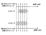
- FIG. 7 is a diagram illustrating an example of the transmission schedule of the first network and the transmission schedule of the second network.
- FIG. 8 is a diagram showing an example in which the starting points of the transmission schedule of the first network and the transmission schedule of the second network are different.
- FIG. 9 is a diagram showing time on the horizontal axis and the voltage applied to the communication lines H and L of the first communication line and the state of the first network on the vertical axis.
- FIG. 10 is a block diagram showing a schematic configuration of a data communication network system according to another embodiment.
- the node that is the earliest ready to send a start-up frame among a plurality of cold start nodes is the preceding cold start node. Then, the other nodes connected to the data communication network have the transmission schedule start point determined by the preceding cold start node. Therefore, even if, for example, there is a node that wants to determine the starting point of the transmission schedule among a plurality of nodes connected to the data communication network, the node cannot always determine the starting point of the transmission schedule.
- the data communication network system includes a control unit that can set the communication line of the network to a communication prohibited state at a node where the starting point of the transmission schedule is to be determined. Then, the node that wants to determine the starting point of the transmission schedule cancels the communication prohibited state of the communication line of the network by the control means in a state where communication is possible.
- a node that wants to determine the starting point of the transmission schedule can set the starting point of the transmission schedule, and can start communication at a desired timing. It is to make.
- FIG. 1 shows a data communication network in which a node A11, a node B12, a node C13, and a node D14 are connected to a common communication line H and a communication line L, respectively, taking a bus topology as an example.
- the node A11 is a node for which the starting point of the transmission schedule is determined at its own timing.
- a control unit is mounted on the node A11, and a predetermined voltage is applied to the communication line H and the communication line L by the control unit.
- the other nodes (node B12, node C13, and node D14 in the example shown in FIG. 1) are in a state where communication cannot be started. Then, by releasing the voltages applied to the communication line H and the communication line L at a predetermined timing, the transmission schedule start point can be determined at the timing of itself (node A11).
- the nodes A11, B12, C13, and D14 communicate with each other using a time division multiplex communication method in which each of the nodes is shared.
- a communication protocol that defines a time-triggered communication procedure.
- An example of a communication protocol for the data communication network system according to the present embodiment is a FlexRay (registered trademark) protocol.
- the communication protocol of the data communication network system according to the present embodiment will be described below using the FlexRay protocol as an example. Since the FlexRay protocol is a known technique, items directly related to the description of the present embodiment will be described, and descriptions of items not directly related to the description of the present embodiment will be omitted.
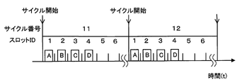
- FIG. 2 is a diagram illustrating an example of a communication pattern based on the FlexRay protocol.
- the FlexRay protocol transmission of a frame (message) is performed based on a time slot obtained by dividing a certain communication cycle, and the transmission right in each time slot is defined by a communication schedule.
- the slot ID is 1 and the terminal A (for example, the node A11 shown in FIG. 1)
- the slot ID is 2 and the terminal B (for example, the node B12 shown in FIG. 1)
- the slot ID is 3 and the terminal A frame transmission right is given to C (for example, node C13 shown in FIG. 1), slot ID 4 and terminal D (for example, node D14 shown in FIG. 1).
- each of the nodes needs to establish time synchronization and integrate it into the network.
- time synchronization is established by matching the common time.
- FIG. 3 is a time chart of a communication cycle showing an example until the node A11, the node B12, the node C13, and the node D14 establish time synchronization and a network is formed.
- description will be made assuming that node A11, node B12, and node C13 are cold start nodes and node D14 is a non-cold start node.
- the node that can set its own unique time to the common time used in the communication network and can start the communication schedule at the common time is referred to as the preceding cold start node. Call it.
- the node A11 becomes a preceding cold start node the node B12 and the node C13 are referred to as subsequent cold start nodes.
- the subsequent cold start node is a node that follows the preceding cold start node but can cooperate in synchronizing time synchronization.
- the non-cold start node (that is, the node D14 in this description) is a node that cannot synchronize with itself only by synchronizing with the time synchronization of the cold start node.
- subsequent cold start nodes and non-cold start nodes may be referred to as integration nodes.
- each node is Each initialization process is performed so that communication can be started. Then, the node A11, which is the preceding cold start node, completes initialization and enters Ready (a state in which a transition to the cold start listen state) can be made.
- the node A11 that has entered the cold start listening state confirms that no other node is communicating, and enters the collision resolution state. Thereafter, the node A11 first transmits a CAS symbol (A-CAS in FIG. 3), and then enters a communication cycle. Note that this cycle number is set to 0, and the node A11 starts transmitting a startup frame (A-st).
- the node A11 transmits a start-up frame (A-st) in the time slot specified by the communication schedule in the collision resolution state.
- the node B12, the node C13, and the node D14 which are integrated nodes, first observe the communication line until a startup frame is received in an even communication cycle.
- the integration node succeeds in receiving the startup frame (A-st0) in the even communication cycle (that is, cycle number 0)
- the integration node calculates the startup frame reception time.
- the subsequent odd communication cycle that is, cycle number 1
- the integration node initializes the time specific to the integration node and starts a communication schedule (communication initialization in FIG. 3). Equivalent).
- the subsequent cold start nodes receive the startup frame (A-st2, A and A1) transmitted from the preceding cold start node (that is, node A11).
- the initial clock adjustment is performed based on the difference between the reception time of -st3) and the expected reception time calculated from the communication schedule (corresponding to the startup synchronization in FIG. 3).
- the subsequent cold start node also transmits a startup frame (not shown), and the preceding cold start node performs time synchronization by receiving the startup frame (see FIG. 3 sync frame transmission and consistency check).
- the non-cold start node integrates with the preceding cold start node and the subsequent cold start node that are transmitting the startup frame.
- the common time used in the communication network can be set using the unique time of the preceding cold start node itself, and the integration node establishes time synchronization with respect to the common time, and transmission / reception is performed according to a common schedule.
- the preceding cold start node can determine the starting point of the common time used in the communication network, and can start the communication schedule at the common time.
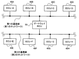
- FIG. 4 is a block diagram showing a schematic configuration of the data communication network system according to the present embodiment.
- the data communication network system according to the present embodiment includes an ECU-A (40A), an ECU-B (40B), an ECU-C (40C), an ECU-D (40D), and a gateway ECU 50.
- a first network configured by connecting to each first communication line, an ECU-E (40E), an ECU-F (40F), an ECU-G (40G), an ECU-H (40H), and a gateway ECU 50
- Each of the second networks is configured by connecting to a second communication line.
- a gateway ECU (Gateway Electronic Control Unit) 50 shown in FIG. 4 is connected to each of the first communication line and the second communication line, and transmits data between the first network and the second network. Relay.
- the gateway ECU 50 is a network node for connecting to a network having a different communication protocol or the same.
- the first network includes ECU-A (40A), ECU-B (40B), ECU-C (40C), ECU-D (40D), and gateway ECU 50. It is assumed that a communication protocol that transmits and receives data according to a time-triggered communication protocol is employed. Note that the first network uses the FlexRay protocol, which is an example of the above-described time-triggered communication protocol.
- the second network in FIG. 4 may use the FlexRay protocol, which is an example of the above-described time-triggered communication protocol, and each ECU has an arbitrary timing when transmission is required.
- An event-triggered communication protocol for transmitting and receiving data for example, CAN (Controller Area Network) protocol may be used.
- the gateway ECU 50 is a node whose transmission schedule is to be determined at its own timing.
- the gateway ECU 50 is provided with the control means described above.
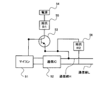
- FIG. 5 is a diagram illustrating an example of an internal configuration of the gateway ECU 50. In FIG. 5, illustration of elements that are not related to the description of the present embodiment is omitted.
- the gateway ECU 50 includes a microcomputer 51 (hereinafter simply referred to as “microcomputer”) 51, a transistor 53, a power supply 54, and the like in addition to the communication IC 52.
- a resistor R1 (55), a resistor R2 (56), a capacitor (not shown), and the like may be provided.
- the microcomputer 51 determines communication start and communication end based on the communication protocol.
- a communication protocol controller and a dedicated element may be provided to determine the start and end of communication.
- the transistor 53 is a switching element that determines a voltage to be applied to the communication line H and the communication line L, and is connected to a power source 54. Note that it is not necessary to perform switching using the transistor 53. For example, any element that can switch the supply of voltage to the communication line H and the communication line L according to the start / end of communication may be used. Further, in the example shown in FIG. 5, the power supply 54 is used to supply the voltage to the communication line H and the communication line L. However, the voltage port (not shown) of the microcomputer 51 or the power supply IC (not shown) is used. ) May be supplied with power.
- control means applies a predetermined voltage to the communication line H and the communication line L in the first communication line in accordance with an instruction from the microcomputer 51.
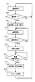
- processing executed by the microcomputer 51 of the control means provided in the gateway ECU 50 will be described with reference to the flowchart shown in FIG. Note that the processing of the flowchart shown in FIG. 6 is repeatedly performed while power is supplied to the gateway ECU 50. That is, for example, it is assumed that the data communication network system shown in FIG. 4 is built in a vehicle and automatically started when power is supplied to the gateway ECU 50.
- step S11 of FIG. 6 the microcomputer 51 performs communication determination, and in the next step S12, determines whether or not communication is completed. Specifically, the microcomputer 51 determines whether each ECU connected to the first communication line shown in FIG. 4 ends the communication. And the microcomputer 51 advances a process to following step S13, when the judgment of step S12 is affirmed (YES). On the other hand, when the microcomputer 51 denies the determination in step S12 (NO), the microcomputer 51 returns the process to step S11.
- the case where the determination in step S12 is affirmed is, for example, a case where the ignition switch of the vehicle is turned off by performing a key operation by the driver of the vehicle.
- step S13 the microcomputer 51 sets the first communication line to the communication prohibited state. Specifically, a voltage that causes a communication prohibited state to be applied to the communication line H and the communication line L of the first communication line by the operation of the transistor 53 is applied to the communication line H and the communication line L.
- the dominant voltage is maintained for devices other than the gateway ECU 50, that is, the ECU-A (40A), the ECU-B (40B), the ECU-C (40C), and the ECU-D (40D).
- the ECU-A (40A), the ECU-B (40B), the ECU-C (40C), and the ECU-D (40D) cannot start communication.
- step S14 the microcomputer 51 performs communication determination, and in the next step S15, determines whether to start communication. And the microcomputer 51 advances a process to following step S16, when the judgment of step S15 is affirmed (YES). On the other hand, when the microcomputer 51 denies the determination in step S15 (NO), the microcomputer 51 returns the process to step S14.
- the determination in step S15 is affirmed is, for example, a case where the ignition switch of the vehicle is turned ON by a key operation of the driver of the vehicle.
- devices other than the gateway ECU 50 that is, the ECU-A (40A), the ECU-B (40B), the ECU-C (40C), and the ECU-D (40D) are also operated, for example, by the vehicle driver.
- the vehicle driver By performing the above, it is determined that a state where communication is started has occurred due to the ignition switch of the vehicle being turned on.
- step S11 For example, after the driver uses the vehicle, the vehicle is parked and the ignition switch is turned off (YES in step S12), and then the driver turns on the vehicle ignition switch to use the vehicle again. Assume that (YES in step S15). That is, for example, until the ignition switch of the vehicle is turned off and then the ignition switch is turned on again, the control means provided in the gateway ECU 50 controls the communication line H and the communication line L of the first communication line. Thus, a voltage that is in a communication prohibited state continues to be applied.
- step S15 the gateway ECU 50, ECU-A (40A), ECU-B (40B), ECU-C (40C), and ECU-D (40D) start communication.
- step S16 the gateway ECU 50, ECU-A (40A), ECU-B (40B), ECU-C (40C), and ECU-D (40D) communicate with each other in step S16. Perform initialization so that it can start.
- the initialization process is described with reference to a communication cycle time chart showing an example of the process until the network is formed as shown in FIG. 3, and the gateway ECU 50, ECU-A (40A), ECU- Each of B (40B), ECU-C (40C), and ECU-D (40D) transitions to a cold start listening state through initialization.
- the gateway ECU 50 at this time is a device other than the gateway ECU 50, that is, ECU-A (40A), ECU-B (40B), ECU-C (40C), and ECU-D ( 40D) and a message for matching the communication timing need to be transmitted. For this reason, the gateway ECU 50 is initialized prior to devices other than the gateway ECU 50, that is, the ECU-A (40A), the ECU-B (40B), the ECU-C (40C), and the ECU-D (40D). Must be completed.
- step S17 the microcomputer 51 determines whether the gateway ECU 50 is in a communicable state, that is, whether the initialization process has been completed. If the microcomputer 51 affirms the determination in step S17 (YES), the microcomputer 51 proceeds to the next step S18. On the other hand, when the microcomputer 51 denies the determination in step S17 (NO), it returns the process to step S17. That is, when the gateway ECU 50 completes the initialization process and becomes communicable, the determination in step S17 is affirmed (YES).
- step S18 the microcomputer 51 releases the voltage applied to the communication line H and the communication line L so that the communication line H and the communication line L of the first communication line are in the communication prohibited state. Thereafter, in step S19, the gateway ECU 50 transmits a message for synchronization.
- the gateway ECU 50 can start communication at the timing requested by itself. That is, the gateway ECU 50 can determine the starting point of the common time used in the communication network, and can start the communication schedule at the common time.
- the gateway ECU 50 can determine the starting point of the common time used in the communication network, and can start the communication schedule at the common time.
- the ECU-A (40A), the ECU-B (40B), the ECU-C (40C), and the ECU-D (40D) are connected to the first communication line, respectively.
- a second network configured by connecting the ECU-E (40E), the ECU-F (40F), the ECU-G (40G), and the ECU-H (40H) to the second communication line, respectively.
- the gateway ECU 50 is assumed to be a gateway ECU that is connected to each of the first communication line and the second communication line and relays data between the first network and the second network.
- the first network and the second network each employ a communication protocol that transmits and receives data according to a time-triggered communication protocol (for example, the FlexRay protocol).
- FIG. 7 is a diagram illustrating an example of the transmission schedule of the first network and the transmission schedule of the second network. For example, in FIG. 7, assume that the message “A” from the first network is desired to be gatewayed to the second network via the gateway ECU 50 without staying in the gateway ECU 50.
- the gateway ECU 50 when communication is started between the first network and the second network at the same time, the gateway ECU 50 receives the message “A” when the gateway ECU 50 receives the message “A”. 2 m seconds later, it is waited in the gateway ECU 50 and transmitted to the second network.
- gateway ECU 50 Since gateway ECU 50 knows both the transmission schedules in the first network and the second network, as shown in FIG. 8, the time during which message “A” stays in gateway ECU 50 is shortened. For this purpose, instead of starting communication between the first network and the second network at the same time, for example, the transmission start time of the first network can be delayed by 1 ms from the transmission start time of the second network. That's fine. That is, when the transmission start time of the first network is delayed by 2 milliseconds from the transmission start time of the second network, the gateway ECU 50 transmits the message “A” to the second network while receiving the message “A” from the first network. For example, the transmission start time of the first network may be delayed by 1 msec from the transmission start time of the second network.
- FIG. 9 is a diagram showing the time on the horizontal axis, the voltage applied to the communication line H and the communication line L of the first communication line, and the communication state of the first network on the vertical axis.
- ECU-A 40A
- ECU-B 40B
- ECU-C 40C
- ECU-D connected to the first communication line. It is assumed that (40D) ends the communication (YES in step S12 in FIG. 6).
- the voltage which will be in a communication prohibition state is applied to the communication line H and the communication line L of a 1st communication line by the control means provided in gateway ECU50 (step S13 of FIG. 6).
- step S15 in FIG. 6 the control means continues to apply a voltage that causes the communication prohibited state to be applied to the communication line H and the communication line L of the first communication line.
- the control unit causes the communication line H and the communication line L of the first communication line to be in a communication prohibited state. Simultaneously with releasing the voltage applied to H and the communication line L, the gateway ECU 50 transmits a message for synchronization (step S18 and step S19 in FIG. 6).
- the message transmitted by the gateway ECU 50 at the same time as the voltage applied to the communication line H and the communication line L is released corresponds to the CAS symbol transmitted by the node A in FIG. That is, by transmitting a CAS symbol, transmission of a start-up frame is started in the following cycle.
- the start-up frame reception time is calculated, The ECU-specific time is initialized and the communication schedule is started.
- the preceding cold start node can determine the starting point of the transmission schedule at its own timing, but in order to be able to become the preceding cold start node, it is ready to transmit and transmits the CAS symbol earliest. There is a need. That is, by satisfying these conditions, the node A that is the preceding cold start node in the example shown in FIG. 3 corresponds to the gateway ECU 50.
- the dominant voltage is set to the communication line H and the communication line L, and devices other than the gateway ECU 50, that is, ECU-A (40A), ECU-B (40B), ECU-C (40C), and ECU-D (40D) is in a state where communication cannot be started, and when the initialization process of the gateway ECU 50 is completed, the voltage applied to the communication line H and the communication line L is released, and at the same time, a CAS symbol is transmitted.
- the gateway ECU 50 can be a preceding cold start node that can determine the starting point of the schedule, and can determine the starting point of data transmission at a desired timing.
- the gateway ECU 50 can delay the time when the communication of the first network is started by 1 msec from the time when the communication of the second network is started. The time during which the message “A” stays can be shortened.
- the node that wants to determine the starting point of the transmission schedule at its own timing is assumed to be the gateway ECU 50, but the present invention is not limited to this.
- it may be a suspension ECU, a brake ECU, an engine ECU, or the like.
- the suspension ECU controls the damping force and the like by controlling an actuator installed in the damper of the vehicle according to the road surface condition where the vehicle is traveling.
- the suspension ECU needs to immediately control the actuator in accordance with the road surface on which the vehicle is traveling. That is, for example, if the suspension ECU includes the above-described control means, the suspension ECU can transmit data at a timing desired by the suspension ECU, and controls the actuator based on the data immediately after the calculation. Will be able to.
- control means is provided in the node (gateway ECU 50) that wants to determine the starting point of the transmission schedule at its own timing.
- a line may be provided separately.
- all ECUs for example, node A11, node B12, node C13, node D14 in the example shown in FIG. 1 are set to the communication prohibited state when the communication ends.
- the ECU for example, node A11 in the example shown in FIG. 1 whose communication timing is to be controlled is installed in the ECU with software for canceling the communication prohibited state when the communication start is required.
- the other ECUs in the example shown in FIG. 1, for example, the node B12, the node C13, and the node D14
- cancel the communication prohibited state from the ECU that controls the communication timing (for example, voltage fluctuation through the communication line).
- the communication timing for example, voltage fluctuation through the communication line
- an ECU for example, node A11 in the example shown in FIG. 1 whose communication timing is to be controlled has a built-in communication prohibition state release timer, and the communication prohibition state release timer is soft. Above, it sets shorter than other ECUs (in the example shown in Drawing 1, for example, node B12, node C13, and node D14). Specifically, a communication prohibition state release timer is also incorporated in the other ECU, and the communication prohibition release time of the timer is set longer than the ECU whose communication timing is desired to be controlled. If the ECU that wants to control the communication timing cannot instruct the start of communication due to some cause (for example, an error occurs), another ECU may communicate with the communication protocol after the time set in the timer of each ECU has elapsed. It is done.
- the data communication network system according to the present invention is useful for a data communication network system mounted on a vehicle, for example, in which a desired unit can determine the starting point of a communication transmission schedule.
Landscapes
- Engineering & Computer Science (AREA)
- Computer Networks & Wireless Communication (AREA)
- Signal Processing (AREA)
- Small-Scale Networks (AREA)
- Synchronisation In Digital Transmission Systems (AREA)
Abstract
Description
40B…ECU-B
40C…ECU-C
40D…ECU-D
50…ゲートウェイECU
Claims (5)
- 複数の電子制御ユニットが通信線を介してタイムトリガ型の通信プロトコルに従ってネットワーク通信を行うデータ通信ネットワークシステムであって、
前記通信線を予め通信禁止状態に設定し、予め定められたタイミングで前記通信禁止状態を解除する制御手段を備え、
前記複数の電子制御ユニットのうち予め定められた1つのユニットは、前記通信禁止状態が解除された直後に他のユニットと通信タイミングを合わせるための同期合わせメッセージを送信することを特徴とする、データ通信ネットワークシステム。 - 前記ネットワーク通信はゲートウェイを介して他のネットワーク通信と接続されており、
前記制御手段は、前記他のネットワーク通信で規定されている送受信周期に基づいて前記通信禁止状態を解除することを特徴とする、請求項1に記載のデータ通信ネットワークシステム。 - 前記制御手段は、前記複数の電子制御ユニットが通信を終了したときに、前記通信線を通信禁止状態に設定することを特徴とする、請求項1に記載のデータ通信ネットワークシステム。
- 前記制御手段は、前記通信線に予め定められた電圧を印加することにより前記通信禁止状態に設定することを特徴とする、請求項1に記載のデータ通信ネットワークシステム。
- 前記制御手段は、前記複数の電子制御ユニットのうち予め定められた1つのユニットに設置されることを特徴とする、請求項1に記載のデータ通信ネットワークシステム。
Priority Applications (5)
| Application Number | Priority Date | Filing Date | Title |
|---|---|---|---|
| JP2010539958A JP4935932B2 (ja) | 2009-12-02 | 2009-12-02 | データ通信ネットワークシステム |
| EP09845051.3A EP2509263B1 (en) | 2009-12-02 | 2009-12-02 | Data communication network system |
| CN200980118923.4A CN102150396B (zh) | 2009-12-02 | 2009-12-02 | 数据通信网络系统 |
| PCT/JP2009/006536 WO2011067809A1 (ja) | 2009-12-02 | 2009-12-02 | データ通信ネットワークシステム |
| US12/957,849 US8660149B2 (en) | 2009-12-02 | 2010-12-01 | Data communication network system |
Applications Claiming Priority (1)
| Application Number | Priority Date | Filing Date | Title |
|---|---|---|---|
| PCT/JP2009/006536 WO2011067809A1 (ja) | 2009-12-02 | 2009-12-02 | データ通信ネットワークシステム |
Related Child Applications (1)
| Application Number | Title | Priority Date | Filing Date |
|---|---|---|---|
| US12/957,849 Continuation US8660149B2 (en) | 2009-12-02 | 2010-12-01 | Data communication network system |
Publications (1)
| Publication Number | Publication Date |
|---|---|
| WO2011067809A1 true WO2011067809A1 (ja) | 2011-06-09 |
Family
ID=44068841
Family Applications (1)
| Application Number | Title | Priority Date | Filing Date |
|---|---|---|---|
| PCT/JP2009/006536 Ceased WO2011067809A1 (ja) | 2009-12-02 | 2009-12-02 | データ通信ネットワークシステム |
Country Status (5)
| Country | Link |
|---|---|
| US (1) | US8660149B2 (ja) |
| EP (1) | EP2509263B1 (ja) |
| JP (1) | JP4935932B2 (ja) |
| CN (1) | CN102150396B (ja) |
| WO (1) | WO2011067809A1 (ja) |
Cited By (1)
| Publication number | Priority date | Publication date | Assignee | Title |
|---|---|---|---|---|
| US11304166B2 (en) | 2017-08-29 | 2022-04-12 | Toyota Jidosha Kabushiki Kaisha | In-vehicle relay device, information processing system, relay device, information processing device, information processing method, and non- transitory recording medium storing program |
Families Citing this family (21)
| Publication number | Priority date | Publication date | Assignee | Title |
|---|---|---|---|---|
| JP5006443B2 (ja) * | 2008-04-02 | 2012-08-22 | 株式会社オートネットワーク技術研究所 | 車両通信システム |
| US8498276B2 (en) * | 2011-05-27 | 2013-07-30 | Honeywell International Inc. | Guardian scrubbing strategy for distributed time-triggered protocols |
| CN102328655B (zh) * | 2011-07-11 | 2014-04-02 | 北京交通大学 | 一种基于FlexRay总线的车用混合动力系统 |
| US9579198B2 (en) | 2012-03-01 | 2017-02-28 | Twelve, Inc. | Hydraulic delivery systems for prosthetic heart valve devices and associated methods |
| DE102012204586B4 (de) * | 2012-03-22 | 2025-02-27 | Bayerische Motoren Werke Aktiengesellschaft | Gateway, Knoten und Verfahren für ein Fahrzeug |
| CN104272695B (zh) * | 2012-04-20 | 2017-04-19 | 三菱电机株式会社 | 数据处理装置 |
| US9088514B2 (en) | 2012-07-23 | 2015-07-21 | Broadcom Corporation | Flexray communications using ethernet |
| US9925935B2 (en) | 2012-08-24 | 2018-03-27 | Mitsubishi Electric Corporation | In-vehicle communication system and in-vehicle communication method |
| PE20151842A1 (es) | 2013-04-22 | 2016-01-10 | Tlv Co Ltd | Sistema de control de terminales |
| CN104378272B (zh) * | 2014-10-28 | 2019-01-25 | 奇瑞汽车股份有限公司 | 消息传输方法及装置 |
| JP6384733B2 (ja) * | 2015-11-20 | 2018-09-05 | 本田技研工業株式会社 | 通信システム、及び制御装置 |
| JP6515914B2 (ja) | 2016-12-22 | 2019-05-22 | トヨタ自動車株式会社 | 車載ネットワークシステム、中継装置 |
| US10575950B2 (en) | 2017-04-18 | 2020-03-03 | Twelve, Inc. | Hydraulic systems for delivering prosthetic heart valve devices and associated methods |
| US10646338B2 (en) | 2017-06-02 | 2020-05-12 | Twelve, Inc. | Delivery systems with telescoping capsules for deploying prosthetic heart valve devices and associated methods |
| US10709591B2 (en) | 2017-06-06 | 2020-07-14 | Twelve, Inc. | Crimping device and method for loading stents and prosthetic heart valves |
| JP7094670B2 (ja) * | 2017-07-03 | 2022-07-04 | 矢崎総業株式会社 | 設定装置及びコンピュータ |
| JP7042417B2 (ja) * | 2018-09-03 | 2022-03-28 | 株式会社オートネットワーク技術研究所 | 通信装置、送信方法及びコンピュータプログラム |
| JP7298372B2 (ja) * | 2019-07-31 | 2023-06-27 | マツダ株式会社 | 車両制御システム |
| CN111324569A (zh) * | 2020-02-24 | 2020-06-23 | 宁波拓邦智能控制有限公司 | 一种多机通信同步系统、多机通信同步方法及电器 |
| CN114666180B (zh) * | 2022-03-01 | 2023-07-21 | 亿咖通(湖北)技术有限公司 | 一种模拟ecu节点的分配方法、装置、电子设备及存储介质 |
| JP2023169933A (ja) * | 2022-05-18 | 2023-12-01 | トヨタ自動車株式会社 | 制御装置、通信制御方法、通信制御プログラム |
Citations (3)
| Publication number | Priority date | Publication date | Assignee | Title |
|---|---|---|---|---|
| JP2007060400A (ja) | 2005-08-25 | 2007-03-08 | Auto Network Gijutsu Kenkyusho:Kk | 通信タイミング制御方法および通信タイミング制御システム |
| JP2008277873A (ja) * | 2007-04-25 | 2008-11-13 | Auto Network Gijutsu Kenkyusho:Kk | 中継接続ユニット |
| JP2009089166A (ja) * | 2007-10-01 | 2009-04-23 | Fujitsu Microelectronics Ltd | 通信システム |
Family Cites Families (14)
| Publication number | Priority date | Publication date | Assignee | Title |
|---|---|---|---|---|
| JPH03151741A (ja) * | 1989-11-08 | 1991-06-27 | Alpine Electron Inc | マスター端末決定方法 |
| US5517499A (en) * | 1992-05-28 | 1996-05-14 | Telefonaktiebolaget Lm Ericsson | Method and an arrangement for synchronizing two or more communication networks of the time multiplex type |
| JPH0784943A (ja) | 1993-09-17 | 1995-03-31 | Mitsubishi Electric Corp | シリアル通信装置 |
| JPH07219913A (ja) * | 1994-01-28 | 1995-08-18 | Fujitsu Ltd | マルチプロセッサシステムの制御方法及び装置 |
| JPH11261581A (ja) | 1998-03-12 | 1999-09-24 | Omron Corp | データ通信制御装置 |
| EP1199848A3 (en) * | 2000-10-17 | 2003-12-17 | Appairent Technologies, Inc. | Shared time universal multiple access network |
| US20030043793A1 (en) * | 2001-08-31 | 2003-03-06 | Juergen Reinold | Vehicle active network |
| DE10144070A1 (de) * | 2001-09-07 | 2003-03-27 | Philips Corp Intellectual Pty | Kommunikationsnetzwerk und Verfahren zur Steuerung des Kommunikationsnetzwerks |
| DE10147445A1 (de) * | 2001-09-26 | 2003-04-17 | Bosch Gmbh Robert | Verfahren und Vorrichtung zur Übertragung von Informationen auf einem Bussystem und Bussystem |
| EP1355456A1 (en) * | 2002-04-16 | 2003-10-22 | Robert Bosch Gmbh | FlexRay communication protocol |
| JP4627456B2 (ja) * | 2005-05-26 | 2011-02-09 | ルネサスエレクトロニクス株式会社 | 通信システム、サイクルマスタノード及び通信方法 |
| JP4162093B2 (ja) * | 2005-12-09 | 2008-10-08 | 三菱電機株式会社 | 通信システム |
| KR20090049052A (ko) * | 2006-07-19 | 2009-05-15 | 엔엑스피 비 브이 | 노드, 분산형 결함 공차 및/또는 시간 트리거형 통신 시스템, 통신 감시 방법, 및 컴퓨터 판독가능 매체 |
| JP2008306648A (ja) | 2007-06-11 | 2008-12-18 | Nissan Motor Co Ltd | データ中継装置及びデータ中継方法並びに通信ネットワークシステム |
-
2009
- 2009-12-02 EP EP09845051.3A patent/EP2509263B1/en not_active Not-in-force
- 2009-12-02 WO PCT/JP2009/006536 patent/WO2011067809A1/ja not_active Ceased
- 2009-12-02 JP JP2010539958A patent/JP4935932B2/ja not_active Expired - Fee Related
- 2009-12-02 CN CN200980118923.4A patent/CN102150396B/zh not_active Expired - Fee Related
-
2010
- 2010-12-01 US US12/957,849 patent/US8660149B2/en not_active Expired - Fee Related
Patent Citations (3)
| Publication number | Priority date | Publication date | Assignee | Title |
|---|---|---|---|---|
| JP2007060400A (ja) | 2005-08-25 | 2007-03-08 | Auto Network Gijutsu Kenkyusho:Kk | 通信タイミング制御方法および通信タイミング制御システム |
| JP2008277873A (ja) * | 2007-04-25 | 2008-11-13 | Auto Network Gijutsu Kenkyusho:Kk | 中継接続ユニット |
| JP2009089166A (ja) * | 2007-10-01 | 2009-04-23 | Fujitsu Microelectronics Ltd | 通信システム |
Non-Patent Citations (1)
| Title |
|---|
| See also references of EP2509263A4 |
Cited By (1)
| Publication number | Priority date | Publication date | Assignee | Title |
|---|---|---|---|---|
| US11304166B2 (en) | 2017-08-29 | 2022-04-12 | Toyota Jidosha Kabushiki Kaisha | In-vehicle relay device, information processing system, relay device, information processing device, information processing method, and non- transitory recording medium storing program |
Also Published As
| Publication number | Publication date |
|---|---|
| JPWO2011067809A1 (ja) | 2013-04-18 |
| CN102150396A (zh) | 2011-08-10 |
| US20110128855A1 (en) | 2011-06-02 |
| EP2509263B1 (en) | 2016-08-10 |
| EP2509263A4 (en) | 2014-01-15 |
| EP2509263A1 (en) | 2012-10-10 |
| CN102150396B (zh) | 2015-08-26 |
| US8660149B2 (en) | 2014-02-25 |
| JP4935932B2 (ja) | 2012-05-23 |
Similar Documents
| Publication | Publication Date | Title |
|---|---|---|
| JP4935932B2 (ja) | データ通信ネットワークシステム | |
| KR101542016B1 (ko) | 차량 내 이종 네트워크 도메인들 간의 동기화 게이트웨이 장치 및 동기화 방법 | |
| CN103988453B (zh) | 用于使在车载网络的节点中的时钟同步的方法和设置用于实施该方法的节点 | |
| KR20090067152A (ko) | 클러스터 커플러 유닛, 클러스터 동기화 방법 및 네트워크 | |
| US6990540B2 (en) | Method and device for transmitting information on a bus system, and a bus system in which different information is uniquely assigned different information identifiers | |
| JP5099156B2 (ja) | 通信ネットワークシステム、中継端末、マイクロコンピュータ、送受信装置 | |
| CN105577308A (zh) | 使用冗余主时钟提供车载网络时间同步的方法和设备 | |
| JPWO2002089419A1 (ja) | 車両用多重通信装置 | |
| JP2007529163A (ja) | ネットワーク・ノード | |
| JP5296515B2 (ja) | 車両用通信システム | |
| JP4162093B2 (ja) | 通信システム | |
| US10341440B2 (en) | Method and device for transferring messages in a computer network | |
| JP4367528B2 (ja) | シリアル通信装置 | |
| JP2007336267A (ja) | 車載通信システム | |
| WO2013069103A1 (ja) | 電子制御装置及びマイクロコンピュータの制御方法 | |
| JP4673749B2 (ja) | 車両用通信制御ユニットおよび車両用通信制御システム | |
| JP2012231410A (ja) | データ中継装置、車載ネットワーク | |
| Herpel et al. | A simulation approach for the design of safety-relevant automotive multi-ECU systems | |
| US20260025192A1 (en) | Relay device, communication method, and storage medium thereof | |
| JP4341466B2 (ja) | 同期通信システム | |
| JP2022128840A (ja) | 車載通信ネットワークシステム | |
| WO2023147845A1 (en) | Method and data bus head node for determining a propagation delay between the head node on one side and a plurality of other bus nodes of the data bus on the other side, corresponding data bus system and vehicle comprising the data bus system | |
| JP2008103922A (ja) | 通信システム及び通信装置 | |
| JP2026071818A (ja) | 通信システム | |
| JP4130036B2 (ja) | ローカルシステムを有するlanシステム |
Legal Events
| Date | Code | Title | Description |
|---|---|---|---|
| WWE | Wipo information: entry into national phase |
Ref document number: 200980118923.4 Country of ref document: CN |
|
| ENP | Entry into the national phase |
Ref document number: 2010539958 Country of ref document: JP Kind code of ref document: A |
|
| REEP | Request for entry into the european phase |
Ref document number: 2009845051 Country of ref document: EP |
|
| WWE | Wipo information: entry into national phase |
Ref document number: 2009845051 Country of ref document: EP |
|
| 121 | Ep: the epo has been informed by wipo that ep was designated in this application |
Ref document number: 09845051 Country of ref document: EP Kind code of ref document: A1 |
|
| NENP | Non-entry into the national phase |
Ref country code: DE |