WO2011067962A1 - 車両用回転電機 - Google Patents
車両用回転電機 Download PDFInfo
- Publication number
- WO2011067962A1 WO2011067962A1 PCT/JP2010/063224 JP2010063224W WO2011067962A1 WO 2011067962 A1 WO2011067962 A1 WO 2011067962A1 JP 2010063224 W JP2010063224 W JP 2010063224W WO 2011067962 A1 WO2011067962 A1 WO 2011067962A1
- Authority
- WO
- WIPO (PCT)
- Prior art keywords
- claw
- permanent magnet
- shaped magnetic
- rotating electrical
- electrical machine
- Prior art date
- Legal status (The legal status is an assumption and is not a legal conclusion. Google has not performed a legal analysis and makes no representation as to the accuracy of the status listed.)
- Ceased
Links
Images






Classifications
-
- H—ELECTRICITY
- H02—GENERATION; CONVERSION OR DISTRIBUTION OF ELECTRIC POWER
- H02K—DYNAMO-ELECTRIC MACHINES
- H02K21/00—Synchronous motors having permanent magnets; Synchronous generators having permanent magnets
- H02K21/02—Details
- H02K21/04—Windings on magnets for additional excitation ; Windings and magnets for additional excitation
- H02K21/042—Windings on magnets for additional excitation ; Windings and magnets for additional excitation with permanent magnets and field winding both rotating
- H02K21/044—Rotor of the claw pole type
Definitions
- the present invention relates to a rotating electrical machine for a vehicle such as a generator or a motor, and more particularly to a rotating electrical machine for a vehicle suitable for high output and low noise.
- Patent Document 1 in the structure in which the permanent magnets are arranged between the claw-shaped magnetic poles for the purpose of increasing the output, there arises a problem that the magnetic sound increases as the output increases.
- Patent Document 3 in the structure in which the permanent magnet is brought into contact with the claw-shaped magnetic pole on one circumferential side and a predetermined distance is secured with respect to the claw-shaped magnetic pole on the other circumferential side, the permanent magnet and the circumferential direction A spacer needs to be interposed between the other side and the manufacturing process becomes complicated.
- An object of the present invention is to provide a vehicular rotating electrical machine that has a high output and can suppress an increase in magnetic sound accompanying an increase in output by preventing distortion of the gap magnetic flux density and can prevent a manufacturing process from becoming complicated. It is to provide.
- the present invention comprises a stator and a rotor arranged rotatably on the stator via a rotation gap,
- the rotor includes a pair of claw-shaped magnetic poles with a field coil incorporated therein,
- a vehicular rotating electrical machine composed of permanent magnets arranged between the claw-shaped magnetic poles, The permanent magnet is achieved by forming a region having a large magnetic resistance on the rear side in the rotation direction of the claw-shaped pole piece and in the claw tip direction.
- the permanent magnet increases the magnetic force of the surface facing the claw-shaped magnetic pole piece on the rear side in the rotation direction, and weakens the magnetic force on the surface facing the claw-shaped magnetic pole piece on the front side in the rotation direction. It is comprised as follows.
- the permanent magnet has a magnetic body on a surface facing the claw-shaped pole piece on the rear side in the rotation direction, and a magnetic resistance on a surface facing the claw-shaped pole piece on the front side in the rotation direction.
- a large non-magnetic material is arranged.
- the nonmagnetic material is a void.
- the permanent magnet has a substantially trapezoidal shape when viewed from the outer peripheral side of the rotor.
- the permanent magnet has a substantially triangular shape as viewed from the outer peripheral side of the rotor.
- the permanent magnet has a substantially L-shape when viewed from the outer peripheral side of the rotor.
- the nonmagnetic member is made of a resin member.
- the nonmagnetic member is made of a resin member and integrated with the permanent magnet.
- the permanent magnet has a strong magnetic force on a surface facing the claw-shaped pole piece on the rear side in the rotation direction and a weak magnetic force on the surface facing the claw-shaped pole piece on the front side in the rotation direction. It is composed of a magnet.
- FIG. 1 is a longitudinal sectional view showing the overall configuration of a vehicular rotating electrical machine according to a first embodiment.
- the perspective view which shows the structure of the rotor used for the rotary electric machine for vehicles by 1st Embodiment.
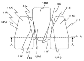
- the plane schematic diagram which looked at the claw-shaped magnetic pole used for the rotor used for the rotating electrical machine for vehicles by a 1st embodiment from the stator side.
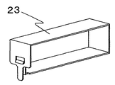
- the perspective view which shows the protective case used for the rotor used for the rotary electric machine for vehicles by 1st Embodiment. Explanatory drawing of the gap magnetic flux in the rotary electric machine for vehicles by 1st Embodiment.
- FIG. 1 is a longitudinal sectional view showing an overall configuration of a rotating electrical machine for a vehicle according to a first embodiment.
- the vehicle alternator 1 of this embodiment includes a stator 5 and a rotor 4 that is disposed on the inner peripheral side of the stator 5 via a gap and is rotatable.
- the rotor 4 includes a pair of claw-shaped magnetic poles 11A and 11B formed of a magnetic material at the center of the shaft 2.
- the claw-shaped magnetic pole 11A includes a boss portion 11A1 around which the field winding 12 is wound, a flange portion 11A2 extending in the radial direction from the end portion of the boss portion 11A, and an axially facing portion from the outer peripheral portion of the flange portion 11A2.
- claw-shaped magnetic pole pieces 11A3 extending in the direction to be performed.
- the claw-shaped magnetic pole 11B has the same configuration as the claw-shaped magnetic pole 11A.
- a field winding 12 is arranged at the central portion (outer peripheral portion of the boss portion 11A1) on the inner peripheral side of the claw-shaped magnetic poles 11A and 11B.
- a permanent magnet 13 for auxiliary excitation is disposed between the claw-shaped pole pieces of the pair of claw-shaped magnetic poles 11A and 11B.
- the rotor 4 is supported by a shaft 2 inserted through inner rings of a front bearing 9 and a rear bearing 10 so as to be relatively rotatable.
- a pulley 3 is attached to the tip of the shaft 2, and a slip ring 14 is provided on the opposite side thereof to contact the brush 15 and supply power to the field winding 12. Further, a front fan 16 and a rear fan 17 of a cooling fan having a plurality of blades on the outer peripheral side are provided on both end faces of the claw-shaped magnetic poles 11A and 11B of the rotor 4, and the fan rotates to rotate the outer periphery from the inner peripheral side. Air is circulated to the side.
- the stator 5 includes a stator core 6 and a stator winding 7.
- the stator 5 is disposed to face the rotor 4 with a slight gap and is held by a front bracket 18 and a rear bracket 19.
- the stator winding 7 is composed of three-phase windings (U phase, V phase, W phase), and the lead wires of the respective windings are connected to the rectifier circuit 21.
- the rectifier circuit 21 is composed of a rectifier element such as a diode, and constitutes a full-wave rectifier circuit.
- the cathode terminal is connected to the terminal 22.
- the terminal on the anode side is electrically connected to the vehicle alternator main body.
- the rear cover 20 serves as a protective cover for the rectifier circuit 21.
- a magnetic circuit that circulates around the rotor 4 and the stator 5 is formed by reaching the pole. Since the magnetic flux generated in the rotor is linked to the stator winding 7 in this way, an AC induced voltage is generated in each of the U-phase, V-phase, and W-phase stator windings, and the three-phase as a whole. An AC induced voltage is generated.
- the AC voltage generated in this way is full-wave rectified and converted into a DC voltage by a rectifier circuit 21 composed of a rectifier element such as a diode.
- the current supplied to the field winding 12 is controlled by an IC regulator (not shown) so that the rectified DC voltage becomes a constant voltage.
- FIG. 2 is a perspective view showing a configuration of a rotor used in the vehicular rotating electrical machine according to the first embodiment.
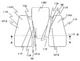
- FIG. 3 is a schematic plan view of the claw-shaped magnetic poles used in the rotor used in the vehicular rotating electrical machine according to the first embodiment when viewed from the stator side.
- FIG. 4 is a cross-sectional view of a main part of the rotor used in the vehicular rotating electrical machine according to the first embodiment.
- FIG. 5 is a perspective view showing a protective case used for the rotor used in the vehicular rotating electrical machine according to the first embodiment. 2 to 5, the same reference numerals as those in FIG. 1 denote the same parts.
- the direction of arrow R is the direction of rotation of the rotor 4.
- the claw-shaped magnetic poles 11A and 11B are arranged in directions in which the claw portions face each other and mesh with each other.
- a permanent magnet 13 is disposed between the claw-shaped magnetic pole pieces 11A3 and 11B3.
- the permanent magnets 13a and 13b have a substantially trapezoidal shape when viewed from the outer peripheral side of the rotor. Note that the radial thickness of the rotor is the same.
- the long side of the trapezoid is located on the rear side in the rotation direction R of the rotor and is in contact with the front side surface 11F in the rotation direction of the claw-shaped magnetic pole piece 11A3.
- the short side of the trapezoid is located on the front side in the rotation direction R of the rotor, and is in contact with the rotation direction rear side surface 11R of the claw-shaped magnetic pole piece 11B3. Therefore, the notch of the substantially trapezoidal permanent magnet 13a faces the claw at the tip of the claw-shaped magnetic pole piece 11B3 located on the front side in the rotation direction R of the rotor, and a gap is formed.
- the long side of the trapezoid is located on the rear side in the rotation direction R of the rotor and is in contact with the front side surface 11F in the rotation direction of the claw-shaped magnetic pole piece 11B3.
- the short side of the trapezoid is located on the front side in the rotation direction R of the rotor, and is in contact with the rotation direction rear side surface 11R of the claw-shaped magnetic pole piece 11A3. Therefore, the notch of the substantially trapezoidal permanent magnet 13a faces the claw at the tip of the claw-shaped magnetic pole piece 11A3 located on the front side in the rotation direction R of the rotor, and the rotation direction R of the permanent magnet 13a and the rotor.
- a gap is formed between the claw portions at the end of the claw-shaped magnetic pole piece 11A3 located on the front side of the claw-shaped magnetic pole piece 11A3.
- the smaller contact area of the portions of the substantially trapezoidal permanent magnets 13a and 13b that are in contact with the claw-shaped magnetic pole pieces 11A3 and 11B3 faces the claw-shaped magnetic poles 11A3 and 11B3 at the rear side in the rotation direction.
- the larger one faces the claw-shaped magnetic poles 11A3 and 11B3 on the front side in the rotation direction.
- the air gap has a large magnetic resistance and is equivalent to a non-magnetic member.
- the permanent magnets 13a and 13b are attracted and fixed to the front side surface 11F in the rotation direction and the rear side surface 11R in the rotation direction of the claw-shaped magnetic poles 11A3 and 11B3 by their magnetic forces. Note that the movement of the permanent magnets 13a and 13b is restricted by the flange 8 described with reference to FIG. 2 with respect to the centrifugal force generated in the radial direction when the rotor rotates.
- FIG. 4 shows the permanent magnet 13 that protects the magnet.
- FIG. 5 shows the overall shape of the protective case 23.
- the output can be increased from the low-speed rotation range.
- the shape of the permanent magnet from the conventional rectangular parallelepiped shape to a substantially trapezoidal shape, the amount of permanent magnet used can be reduced, so the moment of inertia is reduced and the strength of the magnet holder is reduced, which is the highest. The number of rotations can be improved. Furthermore, since the usage amount of the expensive permanent magnet can be reduced, the cost can be suppressed.
- the gap magnetic flux is reduced by reducing the magnetic flux of the claw-shaped magnetic pole on the rear side in the rotational direction compared to the case of arranging a rectangular parallelepiped permanent magnet for reasons described later. Density distortion is improved, and an increase in magnetic sound accompanying an increase in output can be suppressed.
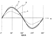
- FIG. 6 shows the magnetic flux distribution in the gap between the stator 5 and the rotor 4.
- the rotating machine Since the rotating machine has a larger amount of magnetic flux on the rear side surface 11R in the rotational direction of the UP ⁇ portion shown in FIG. 3 than the magnetic flux on the front side surface 11F in the rotational direction due to the influence of the armature reaction at the time of loading, the gap magnetic flux density is distorted. Harmonic components due to are included, resulting in annoying magnetic sound.
- the distribution of magnetic flux at this time has a waveform as shown by a thin solid line A in FIG.
- the solid line A is a case where no permanent magnet is arranged.
- the main magnetic flux increases, and a thin solid line A waveform like B is obtained.
- the waveform indicated by the solid line B is merely that the magnetic flux of the waveform indicated by the solid line A is increased as it is, and the gap magnetic flux density includes a harmonic component due to distortion, resulting in an annoying magnetic sound.
- the use of permanent magnets increases the magnetic flux density and increases the output, but the noise level increases more and more.
- the shape of the permanent magnet 13 is substantially trapezoidal, and the smaller contact area of the portion where the permanent magnet 13 is in contact with the substantially trapezoidal claw-shaped magnetic pole pieces 11A3 and 11B3 is the rear base in the rotational direction.
- Installed on the claw-shaped magnetic poles 11A3 and 11B3, and the larger contact area installed on the claw-shaped magnetic poles 11A3 and 11B3 on the front side in the rotation direction the magnetic flux on the front side surface 11F in the rotation direction can be increased and the rear side in the rotation direction.
- the magnetic flux on the side surface 11R can be reduced. This point will be described in detail with reference to FIG. Therefore, the distribution of the gap magnetic flux density becomes a thick solid line C, the gap magnetic flux density can be made close to a sine wave, and an increase in magnetic sound accompanying an increase in output can be suppressed.
- the magnetic flux increases on the front side surface 11F in the rotational direction and the rear side surface 11R in the rotational direction (hereinafter referred to as the magnetizing side), and the distortion of the gap magnetic flux density is not improved. Magnetic sound increases.
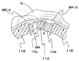
- FIG. 7 is an explanatory diagram of magnetic flux paths in the rotating electrical machine for a vehicle according to the first embodiment of the present invention.
- FIG. 7 shows the AA cross section of FIG. 3, and broken lines MR-A and MR-B represent paths of magnetic flux.
- a broken line MR-A represents a magnetic flux path where a gap MA exists between the substantially trapezoidal permanent magnet 13a and the claw-shaped magnetic poles 11A and 11B. Since a part of the magnetic flux from the permanent magnet 13 flows to the stator core without passing through the claw-shaped magnetic pole on the magnetizing side, the magnetic flux on the magnetizing side can be reduced.
- the magnetic flux path where there is no air gap is a broken line MR-B, and when the permanent magnet on the magnetizing side is partially in contact with the claw-shaped magnetic pole, the magnetic flux passing through the claw-shaped magnetic pole increases and the output increases. Can do.
- the short side of the trapezoid is located on the front side in the rotational direction R of the rotor, and the rear side surface 11R in the rotational direction of the claw-shaped magnetic pole piece 11B3. Touching.
- the notch portion of the substantially trapezoidal permanent magnet 13a faces the tip of the claw portion of the claw-shaped magnetic pole piece 11B3 located on the front side in the rotation direction R of the rotor, and the rotation direction R of the permanent magnet 13a and the rotor
- a gap MA is formed between the front ends of the claw-shaped magnetic pole pieces 11B3 located on the front side.
- the effect of increasing the output is more on the base side than the claw tip of the claw-shaped magnetic pole piece 11B3. large. Accordingly, since the short side of the substantially trapezoidal permanent magnet 13a is in contact with the base side of the claw-shaped magnetic pole piece 11B3, the effect of increasing the output is maintained, while the claw-shaped magnetic pole piece 11B has a claw portion tip side. Since the permanent magnet 13a is located through the gap, the magnetic flux can be reduced as described above, and the magnetic flux density has the same high level as the solid line B as described in FIG. While maintaining, the distribution of magnetic flux density can be made sinusoidal as shown by the solid line C.
- FIG. 8 is an explanatory diagram of the dimensions of the permanent magnet in the vehicular rotating electrical machine according to the first embodiment.
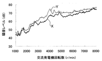
- FIG. 9 is an explanatory diagram of a noise measurement result in the vehicular rotating electrical machine according to the first embodiment.
- a thick solid line X indicates a noise level (dB) when the substantially trapezoidal magnet of the present embodiment is arranged
- a thin solid line Y indicates a noise level (dB) when a rectangular parallelepiped magnet is arranged. Is shown.
- the noise level can be lowered as a whole when the substantially trapezoidal permanent magnet according to the present embodiment is arranged, compared to the conventional permanent magnet having the rectangular parallelepiped shape. .
- the noise level can be lowered by several dB.
- the engine torque is transmitted to the AC generator via the pulley 3.
- the pulley ratio is 3, when the rotational speed of the AC generator is 3000 to 4500 (r / min), the engine rotational speed corresponds to 1000 to 1500 (r / min).
- This engine speed is, for example, the speed when the vehicle is coasting at a low speed, and the noise from the engine is also low. At this time, if the noise level from the AC generator is high, it is very disturbing. However, in this embodiment, the noise level of the AC generator when the vehicle is traveling at a constant speed can be reduced, which is extremely effective.
- the gap magnetic flux density approaches a sine wave shape and the harmonic components are reduced, so that the eddy current generated in the claw-shaped magnetic poles 11A and 11B of the rotor core can be suppressed, and the eddy current It is possible to prevent the temperature from rising. In particular, it is effective when a rare earth magnet is used for the permanent magnet 13, and high temperature demagnetization can be prevented.
- the rotor cores 11A and 11B can be formed in the same shape before and after the axial direction, so that the product cost can be reduced.
- a dedicated spacer is interposed.
- the substantially trapezoidal permanent magnet 13 disposed between the claw-shaped magnetic poles 11A and 11B of the present invention is restricted in movement in the outer diameter direction by the flange 8 portion of the claw-shaped magnetic poles 11A and 11B. Since it is not necessary to interpose a spacer, the manufacturing process can be simplified, and further, since a dedicated spacer is not required, the cost can be reduced.
- the permanent magnet having the magnetoresistive region formed on the rear side in the rotation direction and in the claw tip direction is disposed between the claw-shaped magnetic poles adjacent in the circumferential direction.
- the increase in magnetic sound accompanying the increase in output can be suppressed by realizing a high output while preventing the complication of the noise and improving the distortion of the gap magnetic flux density.
- FIG. 10 is a perspective view of a main part of the rotor for explaining the shape of a permanent magnet used in the rotating electrical machine for a vehicle according to the second embodiment.
- the permanent magnet 13 ⁇ / b> A has a triangular shape as viewed from the outer peripheral side of the rotor, and has a larger opposing gap as it goes to the tip of the claw-shaped magnetic pole piece 11.
- a permanent magnet having a magnetoresistive region on the rear side in the rotational direction and in the claw tip direction between the claw-shaped magnetic poles adjacent in the circumferential direction, the distortion of the gap magnetic flux density is improved. An increase in magnetic sound accompanying an increase in output can be suppressed.
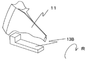
- FIG. 11 is a perspective view of a main part of the rotor for explaining the shape of the permanent magnet used in the rotating electrical machine for a vehicle according to the third embodiment.
- the permanent magnet 13 ⁇ / b> B has an L-shape when viewed from the outer peripheral side of the rotor, and has a larger opposing gap as it goes to the tip of the claw-shaped magnetic pole piece 11.
- a permanent magnet having a magnetoresistive region on the rear side in the rotation direction and in the claw tip direction between the claw-shaped magnetic poles adjacent in the circumferential direction, distortion of the gap magnetic flux density can be improved.
- an increase in magnetic sound accompanying an increase in output can be suppressed.
- FIG. 12 is a perspective view of the main part of the rotor for explaining the shape of the permanent magnet used in the rotating electrical machine for a vehicle according to the fourth embodiment.
- the permanent magnet 13 ⁇ / b> C has a gently curved shape, for example, a substantially elliptical arc shape, as viewed from the outer peripheral side of the rotor, and goes to the tip of the claw-shaped magnetic pole piece 11.
- the opposing gap is enlarged according to
- a permanent magnet having a magnetoresistive region on the rear side in the rotation direction and in the claw tip direction between the claw-shaped magnetic poles adjacent in the circumferential direction, distortion of the gap magnetic flux density can be improved.
- an increase in magnetic sound accompanying an increase in output can be suppressed.
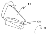
- FIG. 13 is a perspective view of a main part of the rotor for explaining the shape of a permanent magnet used in the rotating electrical machine for a vehicle according to the fifth embodiment.
- the permanent magnet 13 ⁇ / b> D has a rectangular parallelepiped shape in which a triangular pyramid shape having a claw tip direction as a base and a claw root direction as a vertex is cut and is formed at a tip portion of the claw-shaped magnetic pole piece 11.
- the opposite gap is enlarged as it goes.
- a permanent magnet having a magnetoresistive region on the rear side in the rotation direction and in the claw tip direction between the claw-shaped magnetic poles adjacent in the circumferential direction, distortion of the gap magnetic flux density can be improved.
- an increase in magnetic sound accompanying an increase in output can be suppressed.
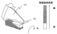
- FIG. 14 is a perspective view of a main part of the rotor for explaining the shape of a permanent magnet used in the rotating electrical machine for a vehicle according to the sixth embodiment.
- the permanent magnet 13 ⁇ / b> E is a composite magnet and has a rectangular parallelepiped shape, but the internal magnetic force is not uniform and has a magnetic force distribution.
- the residual magnetic flux density distribution of the permanent magnet 13E is such that the residual magnetic flux density at the portion facing the rear side portion in the rotation direction of the claw-shaped magnetic pole 11 that contacts the magnetizing side is small, and the residual magnetic flux density at the portion facing the front portion in the rotation direction is small.
- the magnetic flux density is large.
- the composite magnet is manufactured as follows. First, a material having a composition that increases the residual magnetic flux density is placed in a mold and molded. Next, a magnet already molded in the first step in another mold and a material having a composition that makes the residual magnetic flux density slightly smaller than the first material are put in another mold and molded. This process is repeated to obtain magnet materials having a rectangular parallelepiped shape as shown in FIG. By finally magnetizing, a permanent magnet having a different residual magnetic flux density depending on the location as shown in FIG. 14 can be obtained.
- a permanent magnet having a magnetoresistive region on the rear side in the rotation direction and in the claw tip direction between the claw-shaped magnetic poles adjacent to each other in the circumferential direction, the manufacturing process is prevented from becoming complicated.
- an increase in magnetic sound accompanying an increase in output can be suppressed.
- FIG. 15 is a plan view of a principal part showing a configuration of a rotor used in the rotating electrical machine for a vehicle according to the seventh embodiment.
- the same reference numerals as those in FIG. 3 denote the same parts.
- the resin RE is filled in the gaps formed between the substantially trapezoidal notches of the permanent magnets 13a and 13b and the claw-shaped magnetic pole pieces 11A3 and 11B3 shown in FIG. Yes.
- a thermoplastic resin is used as the resin. Resin is filled in the voids and cured by heating.
- a substantially trapezoidal permanent magnet is placed in advance in a rectangular parallelepiped mold, resin is filled in a triangular prism-shaped gap, and heat-molded, so that the substantially trapezoidal permanent magnet and resin are integrated into a rectangular parallelepiped shape. What was shape
- molded can also be used.
- a permanent magnet having a magnetoresistive region on the rear side in the rotation direction and in the claw tip direction between the claw-shaped magnetic poles adjacent to each other in the circumferential direction, the manufacturing process is prevented from becoming complicated.
- an increase in magnetic sound accompanying an increase in output can be suppressed.
- the AC generator for a vehicle has been described as an embodiment of the rotating electrical machine, but if a permanent magnet is employed between the claw-shaped poles, a motor that outputs rotational force,
- the present invention can also be applied to a motor generator that combines power generation and driving.
Landscapes
- Engineering & Computer Science (AREA)
- Power Engineering (AREA)
- Permanent Field Magnets Of Synchronous Machinery (AREA)
- Synchronous Machinery (AREA)
- Iron Core Of Rotating Electric Machines (AREA)
Abstract
高出力であるとともに、ギャップ磁束密度の歪を改善することで、出力増加に伴う磁気音の増加を抑制でき、かつ、製造工程の複雑化を防止できる車両用回転電機を提供することにある。周方向に隣接する爪形磁極11A,11Bの間に、爪形磁極と対向する面の回転方向前側の面積を回転方向後側の面積よりも小さくした永久磁石13を配置する。これにより、低速回転域から出力を増加させることができ、且つギャップ磁束密度の歪を改善でき、出力増加に伴う磁気音の増加を抑制できる。
Description
本発明は、発電機やモータ等の車両用回転電機に係り、特に、高出力且つ低騒音に好適な車両用回転電機に関する。
近年、車両用補機の電動化に伴う負荷増大と、車内の快適性向上のため、高出力且つ低騒音の車両用回転電機が求められている。
高出力化として、周方向に隣合う爪形磁極間に永久磁石を配置し、その爪形磁極間の漏洩磁束を減らして、発電に寄与する有効磁束を増量させることにより出力を向上させるものが知られている(例えば、特許文献1参照)。
しかしながら、特許文献1記載のように、出力増加を目的に爪形磁極間に永久磁石を配置する構造では、出力増加に伴い、磁気音が増加するという問題が生じる。
それに対して、低騒音化の手法として、固定子と回転子との間の空隙(以下、ギャップと呼ぶ)距離を、爪形磁極回転方向前側より回転方向後側を大きくした構造のものが知られている(例えば、特許文献2参照)。また、永久磁石を周方向一方側の爪形磁極に当接させ、周方向他方側の爪形磁極に対して所定距離を確保する構造のものが知られている(例えば、特許文献3参照)。
しかしながら、特許文献2記載のように、ギャップ距離を爪形磁極回転方向前側より回転方向後側を大きくした構造では、回転子鉄心が軸方向前後で異なる形状となるため製品のコストを上昇させるという問題がある。さらに、この構造では、永久磁石を保持する鍔部の回転方向外径側の肉厚が薄くなるため、回転子の回転に伴う遠心力で外径側へ力が働くことにより鍔部の強度が持たないといった懸念もある。
また、特許文献3記載のように、永久磁石を周方向一方側の爪形磁極に当接させ、周方向他方側の爪形磁極に対して所定距離を確保する構造では、永久磁石と周方向他方側との間にスペーサを介設する必要があり、製造工程が複雑となる。
本発明の目的は、高出力であるとともに、ギャップ磁束密度の歪を改善することで、出力増加に伴う磁気音の増加を抑制でき、かつ、製造工程の複雑化を防止できる車両用回転電機を提供することにある。
本発明は、固定子と、該固定子に回転空隙を介して回転可能に配置された回転子とから構成され、
該回転子は、界磁コイルを内装した一対の爪形磁極と、
該爪形磁極間に配置される永久磁石から構成される車両用回転電機であって、
前記永久磁石は、前記爪形磁極片の回転方向後側でかつ爪先端方向に磁気抵抗の大きな領域を形成することによって達成される。
該回転子は、界磁コイルを内装した一対の爪形磁極と、
該爪形磁極間に配置される永久磁石から構成される車両用回転電機であって、
前記永久磁石は、前記爪形磁極片の回転方向後側でかつ爪先端方向に磁気抵抗の大きな領域を形成することによって達成される。
本発明の好ましくは、前記永久磁石は、回転方向後側となる前記爪形磁極片に対向する面の磁力を強く、回転方向前側となる前記爪形磁極片に対向する面の磁力を弱くなるように構成したものである。
本発明の好ましくは、前記永久磁石は、回転方向後側となる前記爪形磁極片に対向する面には磁性体を、回転方向前側となる前記爪形磁極片に対向する面には磁気抵抗の大きな非磁性体を配置したものである。
本発明の好ましくは、前記非磁性体は、空隙である。
本発明の好ましくは、前記永久磁石は、前記回転子の外周側から見た形状が略台形形状をしているものである。
本発明の好ましくは、前記永久磁石は、前記回転子の外周側から見た形状が略三角形状をしているものである。
本発明の好ましくは、前記永久磁石は、前記回転子の外周側から見た形状が略L字形状をしているものである。
本発明の好ましくは、前記非磁性部材は、樹脂部材からなるものである。
本発明の好ましくは、前記非磁性部材は、樹脂部材からなり、前記永久磁石と一体化されているものである。
本発明の好ましくは、前記永久磁石は、回転方向後側となる前記爪形磁極片に対向する面の磁力が強く、回転方向前側となる前記爪形磁極片に対向する面の磁力が弱い複合磁石で構成されているものである。
本発明によれば、高出力であるとともに、ギャップ磁束密度の歪を改善することで、出力増加に伴う磁気音の増加を抑制でき、かつ、製造工程の複雑化を防止できるものとなる。
以下、図1~図9を用いて、第1の実施形態による車両用回転電機の構成及び動作について説明する。
最初に、図1を用いて、本実施形態による車両用回転電機の全体構成について説明する。
図1は、第1の実施形態による車両用回転電機の全体構成を示す縦断面図である。
本実施形態の車両用交流発電機1は、固定子5と、固定子5の内周側にギャップを介して配置され、回転自在な回転子4とを備えている。
回転子4は、シャフト2の中心部に磁性材料にて成形された一対の爪形磁極11A,11Bを備えている。例えば、爪形磁極11Aは、界磁巻線12が巻装されるボス部11A1と、ボス部11Aの端部から径方向に延びるフランジ部11A2と、フランジ部11A2の外周部から軸方向の対峙する方向に延伸する爪形磁極片11A3とからなる。爪形磁極11Bも、爪形磁極11Aと同様な構成である。爪形磁極11A,11Bの内周側の中心部(ボス部11A1の外周部)には、界磁巻線12が配置されている。一対の爪形磁極11A,11Bの爪形磁極片の間には、補助励磁用の永久磁石13が配置されている。回転子4は、フロントベアリング9及びリヤベアリング10の内輪にシャフト2が挿通され、相対回転自在に支持されている。
シャフト2の先端にはプーリ3が取り付けられており、その反対側にはスリップリング14が設けられ、ブラシ15と接触し界磁巻線12に電力を供給している。更に、回転子4の爪形磁極11A,11Bの両端面には、外周側に複数の羽根を有する冷却ファンのフロントファン16とリヤファン17が設けられ、ファンが回ることで、内周側から外周側に空気を流通させるようになっている。
一方、固定子5は、固定子鉄心6と固定子巻線7から構成される。固定子5は、回転子4と僅かなギャップを介して対向配置され、フロントブラケット18とリヤブラケット19によって保持されている。
固定子巻線7は、3相巻線(U相、V相、W相)で構成されており、それぞれの巻線の口出し線は、整流回路21に接続されている。整流回路21は、ダイオード等の整流素子から構成され、全波整流回路を構成している。例えばダイオードの場合、カソード端子はターミナル22に接続されている。また、アノード側の端子は、車両用交流発電機本体に電気的に接続されている。リヤカバー20は、整流回路21の保護カバーの役割を果たしている。
次に、発電動作について説明する。エンジンの始動に伴ってクランクシャフトからベルトを介してプーリ3に回転が伝達されるため、シャフト2を介して回転子4が回転する。ここで、回転子4に設けられた界磁巻線12にスリップリング14を介してブラシ15から直流電流を供給すると、界磁巻線12の内外周を周回する磁束が生じるため、回転子4における爪形磁極11A,11BにN極、又は、S極が周方向に交互に形成される。この界磁巻線12による磁束は、フロント側爪形磁極11AのN極から固定子鉄心6を通って固定子巻線7の周りを周回し、回転子4のリヤ側爪形磁極11BのS極に到達することで回転子4と固定子5を周回する磁気回路が形成される。このように回転子にて生じた磁束が固定子巻線7と鎖交するため、U相、V相、W相の固定子巻線それぞれに交流誘起電圧が発生し、全体としては3相の交流誘起電圧が生じる。
このように発電された交流電圧は、ダイオード等の整流素子で構成された整流回路21によって、全波整流されて直流電圧に変換される。整流された直流電圧が一定電圧になるようにICレギュレータ(図示せず)で界磁巻線12に供給する電流を制御している。
次に、図2~図5を用いて、本実施形態による車両用回転電機に用いる回転子の構成について説明する。
図2は、第1の実施形態による車両用回転電機に用いる回転子の構成を示す斜視図である。図3は、第1の実施形態による車両用回転電機に用いる回転子に用いる爪形磁極を固定子側から見た平面模式図である。図4は、第1の実施形態による車両用回転電機に用いる回転子の要部断面図である。図5は、第1の実施形態による車両用回転電機に用いる回転子に用いる保護ケースを示す斜視図である。なお、図2~図5において、図1と同一符号は、同一部分を示している。
図2において、矢印R方向が回転子4の回転方向である。爪形磁極11A,11Bは、その爪部が互いに対向するとともに、互いに噛み合う方向に配置される。図2に示すように、爪形磁極片11A3,11B3間に、永久磁石13が配置される。図2及び図4に示すように、永久磁石13が、回転子回転による遠心力で外径方向へ移動するのを規制する鍔部8がある。
図3に示すように、永久磁石13a,13bは、回転子の外周側から見たときの形状が略台形形状である。なお、回転子の径方向の厚さは同じである。ここで、永久磁石13aに着目すると、台形の長辺が、回転子の回転方向Rの後ろ側に位置し、爪形磁極片11A3の回転方向前側側面11Fに接触している。また、台形の短辺が、回転子の回転方向Rの前側に位置し、爪形磁極片11B3の回転方向後側側面11Rに接触している。従って、略台形形状の永久磁石13aの切り欠き部が、回転子の回転方向Rの前側に位置する爪形磁極片11B3の先端の爪部に対向し、空隙が形成されている。
また、永久磁石13bに着目しても、同様に、台形の長辺が、回転子の回転方向Rの後ろ側に位置し、爪形磁極片11B3の回転方向前側側面11Fに接触している。また、台形の短辺が、回転子の回転方向Rの前側に位置し、爪形磁極片11A3の回転方向後側側面11Rに接触している。従って、略台形形状の永久磁石13aの切り欠き部が、回転子の回転方向Rの前側に位置する爪形磁極片11A3の先端の爪部に対向し、永久磁石13aと回転子の回転方向Rの前側に位置する爪形磁極片11A3の先端の爪部の間には空隙が形成されている。
すなわち、略台形形状の永久磁石13a,13bの爪形磁極片11A3,11B3と接触する部分の接触面積の小さい方が回転方向後側根元の爪形磁極11A3,11B3に面しており、接触面積の大きい方が回転方向前側の爪形磁極11A3,11B3に面している。
空隙は、磁気抵抗が大きく、非磁性部材と同等である。
永久磁石13a,13bは、それぞれが有する磁力により、爪形磁極11A3,11B3の回転方向前側側面11F及び回転方向後側側面11Rに吸着し、固定される。なお、回転子が回転したときに半径方向に生じる遠心力に対しては、永久磁石13a,13bは、図2にて説明した鍔部8により移動を規制される。
図4に示すように、永久磁石13は磁石を保護するケース23で覆われている。図5は、保護ケース23の全体形状を示している。
以上のように、爪形磁極11A,11B間に永久磁石13を配置することにより、低速回転域から出力を増加させることができる。また、永久磁石の形状を、従来の直方体形状から略台形形状とすることにより、永久磁石の使用量が少なくて済むため、慣性モーメントの低減や、磁石保持部の鍔強度が緩和されるため最高回転数を向上させることができる。さらには高価である永久磁石の使用量を減らすことができるため、コストを抑制することができる。
それに加えて、略台形形状の永久磁石を配置することで、後述する理由により、直方体形状の永久磁石を配置した場合と比較し、回転方向後側爪形磁極の磁束が減少することでギャップ磁束密度の歪が改善され、出力増加に伴う磁気音の増加を抑制できる。
次に、図6~図9を用いて、本実施形態による車両用回転電機に用いる回転子によって磁気音を低減できる理由について説明する。
最初に、図6を用いて、本実施形態による車両用回転電機におけるギャップ磁束について説明する。
図6は、固定子5と回転子4の間のギャップの磁束分布を示している。
回転機は、負荷時において電機子反作用の影響により、図3に示したUPφ部分の回転方向後側側面11Rの磁束が回転方向前側側面11Fの磁束に比べて多いため、ギャップ磁束密度には歪による高調波成分が含まれ、耳障りな磁気音となる。このときの磁束の分布は、図6中の細い実線Aのような波形となる。なお、実線Aは、永久磁石を配置しない場合である。
また、回転方向後側側面11Rと回転方向前側側面11Fとの間に、高出力化を可能とする補助励磁用の直方体形状の永久磁石を配置することで主磁束が増加し、中細の実線Bのような波形となる。実線Bで示す波形は、実線Aで示す波形の磁束がそのまま大きくなっただけであり、ギャップ磁束密度には歪による高調波成分が含まれ、耳障りな磁気音となる。しかも、永久磁石を用いることで磁束密度が大きくなり、高出力化できるが、騒音レベルは益々増加する。
そこで、本実施形態では、永久磁石13の形状を略台形形状として、永久磁石13を略台形形状の爪形磁極片11A3,11B3と接触する部分の接触面積の小さい方が回転方向後側根元の爪形磁極11A3,11B3に設置し、接触面積の大きい方が回転方向前側の爪形磁極11A3,11B3に設置することで、回転方向前側側面11Fの磁束を増加させることができ、且つ回転方向後側側面11Rの磁束を減らすことができる。なお、この点については、図7を用いて詳述する。そのため、ギャップ磁束密度の分布は、太い実線Cとなり、ギャップ磁束密度を正弦波に近づけることができ、高出力化に伴う磁気音の増加を抑制できる。
直方体形状の磁石を配置するだけでは、回転方向前側側面11F及び回転方向後側側面11R(以下、増磁側と呼ぶ)とも磁束が増加しギャップ磁束密度の歪は改善されず、出力増加に伴い磁気音が増加する。
次に、図7を用いて、本実施形態による車両用回転電機における磁束経路について説明する。
図7は、本発明の第1の実施形態による車両用回転電機における磁束経路の説明図である。
図7は、図3のA-A断面を示したものであり、破線MR-A,MR-Bは磁束の経路を表している。破線MR-Aは、略台形形状の永久磁石13aと爪形磁極11A,11Bとの間に空隙MAがある箇所の磁束経路を表す。永久磁石13からの磁束の一部は、増磁側の爪形磁極を通らず固定子鉄心へと磁束が流れるため、増磁側の磁束を減らすことができる。一方、空隙が無い箇所の磁束経路は、破線MR-Bとなり、増磁側の永久磁石を一部爪形磁極に接触させることで、爪形磁極を通る磁束が増加し、出力を増加することができる。
ここで、図3にて説明したように、永久磁石13aについて見た場合、台形の短辺が、回転子の回転方向Rの前側に位置し、爪形磁極片11B3の回転方向後側側面11Rに接触している。そして、略台形形状の永久磁石13aの切り欠き部が、回転子の回転方向Rの前側に位置する爪形磁極片11B3の爪部先端に対向し、永久磁石13aと回転子の回転方向Rの前側に位置する爪形磁極片11B3の爪部先端の間には空隙MAが形成されている。爪形磁極片11B3の回転方向後ろ側に直方体形状の永久磁石が接触している場合についてみると、出力を上昇させる効果は、爪形磁極片11B3の爪部先端部よりも根元側の方が大きい。従って、略台形形状の永久磁石13aの短辺が爪形磁極片11B3の根元側に接触しているので、出力を上昇させる効果は維持され、一方、爪形磁極片11Bの爪部先端側では、空隙を介して永久磁石13aが位置しているので、上述の説明のように、磁束を減らすことができ、図6にて説明したように、磁束密度は、実線Bと同様の高いレベルを維持しつつ、実線Cのように磁束密度の分布を正弦波形状にすることができる。
次に、図8を用いて、本実施形態による車両用回転電機における永久磁石の寸法について説明する。
図8は、第1の実施形態による車両用回転電機における永久磁石の寸法の説明図である。
ここで、略台形形状の磁石を配置した場合の最良の寸法関係について説明する。爪磁極鉄心11の軸方向長さLに対して永久磁石13の長さL1は、L1=0.67×Lである。また、略台形形状を形成する寸法関係は、L2=0.06×L1、W2=0.75×W1である。
なお、径方向の厚さHは厚い方が望ましいが、本実施例では界磁巻線12のエリア確保のため爪形磁極片根元の厚さと略同等としている。
なお、径方向の厚さHは厚い方が望ましいが、本実施例では界磁巻線12のエリア確保のため爪形磁極片根元の厚さと略同等としている。
次に、図9を用いて、本実施形態による車両用回転電機における騒音測定結果について説明する。
図9は、第1の実施形態による車両用回転電機における騒音測定結果の説明図である。
図9において、太い実線Xは、本実施形態の略台形形状の磁石を配置した場合の騒音レベル(dB)を示し、細い実線Yは、直方体形状の磁石を配置した場合の騒音レベル(dB)を示している。
図9に示すように、騒音レベルは、従来の直方体形状の永久磁石を配置したものに対して、本実施形態の略台形形状の永久磁石を配置したものでは、全体的に低下することができる。特に、交流発電機の回転数が3000~4500(r/min)付近では、数dB程度騒音レベルを低くできる。
交流発電機には、エンジンの回転力がプーリ3を介して伝達される。プーリ比を3とすると、交流発電機の回転数が3000~4500(r/min)の時、エンジン回転数は1000~1500(r/min)に相当する。このエンジン回転数は、例えば車両が低速でコースト走行しているときの回転数であり、エンジンからの騒音も低い状態であり、このとき、交流発電機からの騒音レベルが高いと、非常に耳障りとなるが、本実施形態では、車両の定速走行時の交流発電機の騒音レベルを低下できるので、きわめて効果的である。
以上説明した磁石の形態により、ギャップ磁束密度が正弦波形状に近づき高調波成分を低減させることで、回転子鉄心の爪形磁極11A,11Bに発生するうず電流を抑制することができ、うず電流による温度上昇を防止することができる。特に永久磁石13に希土類磁石を使用する場合は有効であり、高温減磁を防ぐことができる。
また、ギャップ距離を爪形磁極回転方向前側より回転方向後側を大きくした構造とは異なり、回転子鉄心11A,11Bを軸方向前後で同一形状とすることができるため、製品コストを低減できる。
さらに、永久磁石13を周方向一方側の爪形磁極11A,11Bに当接させ、周方向他方側の爪形磁極11A,11Bに対して所定距離を確保する構造では専用スペーサを介在させているが、本発明の爪形磁極11A,11B間に配置されている略台形形状の永久磁石13は、爪形磁極11A,11Bの鍔8部により外径方向への移動を規制されるため、専用スペーサを介在させる必要がないことから製造工程を簡略化でき、さらには専用のスペーサを必要としないためコストを低減することができる。
以上説明したように、本実施形態によれば、周方向に隣接する爪形磁極間に、回転方向後側で且つ爪先端方向に磁気抵抗領域を形成した永久磁石を配置することで、製造工程の複雑化を防止しつつ高出力を実現し、ギャップ磁束密度の歪を改善することで、出力増加に伴う磁気音の増加を抑制できるものとなる。
次に、図10を用いて、第2の実施形態による車両用回転電機の構成について説明する。なお、本実施形態による車両用回転電機の全体構成は、図1に示したものと同様である。
図10は、第2の実施形態による車両用回転電機に用いる永久磁石の形状を説明するための回転子の要部斜視図である。
図10に示すように、永久磁石13Aは、回転子の外周側方向から見た形状を、三角形状とし、かつ、爪形磁極片11の先端部に行くに従って対向空隙を大きくしている。
本実施形態によっても、周方向に隣接する爪形磁極間に、回転方向後側で且つ爪先端方向に磁気抵抗領域を形成した永久磁石を配置することで、ギャップ磁束密度の歪を改善し、出力増加に伴う磁気音の増加を抑制することができる。
次に、図11を用いて、第3の実施形態による車両用回転電機の構成について説明する。なお、本実施形態による車両用回転電機の全体構成は、図1に示したものと同様である。
図11は、第3の実施形態による車両用回転電機に用いる永久磁石の形状を説明するための回転子の要部斜視図である。
図11に示すように、永久磁石13Bは、回転子の外周側方向から見た形状を、L字形状とし、かつ、爪形磁極片11の先端部に行くに従って対向空隙を大きくしている。
本実施形態によっても、周方向に隣接する爪形磁極間に、回転方向後側で且つ爪先端方向に磁気抵抗領域を形成した永久磁石を配置することで、ギャップ磁束密度の歪を改善することで、出力増加に伴う磁気音の増加を抑制できるものとなる。
次に、図12を用いて、第4の実施形態による車両用回転電機の構成について説明する。なお、本実施形態による車両用回転電機の全体構成は、図1に示したものと同様である。
図12は、第4の実施形態による車両用回転電機に用いる永久磁石の形状を説明するための回転子の要部斜視図である。
図12に示すように、永久磁石13Cは、回転子の外周側方向から見た形状を、なだらかな曲面形状、例えば略1/4楕円弧形状とし、かつ、爪形磁極片11の先端部に行くに従って対向空隙を大きくしている。
本実施形態によっても、周方向に隣接する爪形磁極間に、回転方向後側で且つ爪先端方向に磁気抵抗領域を形成した永久磁石を配置することで、ギャップ磁束密度の歪を改善することで、出力増加に伴う磁気音の増加を抑制できるものとなる。
次に、図13を用いて、第5の実施形態による車両用回転電機の構成について説明する。なお、本実施形態による車両用回転電機の全体構成は、図1に示したものと同様である。
図13は、第5の実施形態による車両用回転電機に用いる永久磁石の形状を説明するための回転子の要部斜視図である。
図13に示すように、永久磁石13Dは、直方体形状から、爪先端方向を底辺、爪根元方向を頂点とする三角錐の形をカットした形状とし、かつ、爪形磁極片11の先端部に行くに従って対向空隙を大きくしている。
本実施形態によっても、周方向に隣接する爪形磁極間に、回転方向後側で且つ爪先端方向に磁気抵抗領域を形成した永久磁石を配置することで、ギャップ磁束密度の歪を改善することで、出力増加に伴う磁気音の増加を抑制できるものとなる。
次に、図14を用いて、第6の実施形態による車両用回転電機の構成について説明する。なお、本実施形態による車両用回転電機の全体構成は、図1に示したものと同様である。
図14は、第6の実施形態による車両用回転電機に用いる永久磁石の形状を説明するための回転子の要部斜視図である。
図14に示すように、永久磁石13Eは、複合磁石であり、直方体形状であるが、その内部の磁力が一様ではなく、磁力の分布を有している。永久磁石13Eの残留磁束密度分布は、増磁側に当る爪形磁極11の回転方向後側部分に面している箇所の残留磁束密度は小さく、回転方向前側部分に面している箇所の残留磁束密度は大きいものである。
複合磁石は、次のようにして製造される。最初に残留磁束密度が大きくなるような組成を有する材料を型に入れ、成形する。次に、別の型に第1工程で成形済みの磁石と、最初の材料よりも残留磁束密度が少し小さくなるような組成を有する材料を別の型に入れ、成形する。これを繰り返して、図14に示すような直方体形状で、それぞれ場所によって残留磁束密度が異なる磁石材料を得る。最後に着磁することにより、図14に示すような場所によって残留磁束密度が異なる永久磁石を得ることができる。
本実施形態によっても、周方向に隣接する爪形磁極間に、回転方向後側で且つ爪先端方向に磁気抵抗領域を形成した永久磁石を配置することで、製造工程の複雑化を防止しつつ高出力を実現し、ギャップ磁束密度の歪を改善することで、出力増加に伴う磁気音の増加を抑制できるものとなる。
次に、図15を用いて、第7の実施形態による車両用回転電機の構成について説明する。なお、本実施形態による車両用回転電機の全体構成は、図1に示したものと同様である。
図15は、第7の実施形態による車両用回転電機に用いる回転子の構成を示す要部平面図である。なお、図3と同一符号は同一部分を示している。
本実施形態においては、図3に示した永久磁石13a,13bの略台形形状の切り欠き部と爪形磁極片11A3,11B3との間に形成される空隙の部分に、樹脂REを充填している。樹脂は熱可塑性樹脂を用いる。空隙の部分に樹脂を充填し、加熱して硬化させている。また、予め、直方体形状の型の中に略台形形状の永久磁石を配置し、三角柱状の隙間に樹脂を充填して加熱成形して、略台形形状の永久磁石と樹脂とを直方体形状に一体成形したものを用いることもできる。
本実施形態によっても、周方向に隣接する爪形磁極間に、回転方向後側で且つ爪先端方向に磁気抵抗領域を形成した永久磁石を配置することで、製造工程の複雑化を防止しつつ高出力を実現し、ギャップ磁束密度の歪を改善することで、出力増加に伴う磁気音の増加を抑制できるものとなる。
なお、以上の各実施形態では、回転電機の一実施形態として車両用交流発電機について説明を行ったが、爪形状極間に永久磁石を採用していれば、回転力を出力するモータや、発電と駆動を兼ねたモータジェネレータ等にも適用することができる。
1…車両用交流発電機
2…シャフト
3…プーリ
4…回転子
5…固定子
6…固定子鉄心
7…固定子巻線
8…鍔
9…フロントベアリング
10…リヤベアリング
11,11A,11B…爪形磁極
12…界磁巻線
13…永久磁石
14…スリップリング
15…ブラシ
16…フロントファン
17…リヤファン
18…フロントブラケット
19…リヤブラケット
20…リヤカバー
21…整流回路
22…ターミナル
23…永久磁石ケース
24…ギャップ磁束密度
25…磁束経路
2…シャフト
3…プーリ
4…回転子
5…固定子
6…固定子鉄心
7…固定子巻線
8…鍔
9…フロントベアリング
10…リヤベアリング
11,11A,11B…爪形磁極
12…界磁巻線
13…永久磁石
14…スリップリング
15…ブラシ
16…フロントファン
17…リヤファン
18…フロントブラケット
19…リヤブラケット
20…リヤカバー
21…整流回路
22…ターミナル
23…永久磁石ケース
24…ギャップ磁束密度
25…磁束経路
Claims (10)
- 固定子と、該固定子に回転空隙を介して回転可能に配置された回転子とから構成され、
該回転子は、界磁コイルを内装した一対の爪形磁極と、
該爪形磁極間に配置される永久磁石から構成される車両用回転電機であって、
前記永久磁石は、前記爪形磁極片の回転方向後側でかつ爪先端方向に磁気抵抗の大きな領域を形成していることを特徴とする車両用回転電機。 - 請求項1記載において、
前記永久磁石は、回転方向後側となる前記爪形磁極片に対向する面の磁力を強く、回転方向前側となる前記爪形磁極片に対向する面の磁力を弱くなるように構成していることを特徴とする車両用回転電機。 - 請求項1記載において、
前記永久磁石は、回転方向後側となる前記爪形磁極片に対向する面には磁性体を、回転方向前側となる前記爪形磁極片に対向する面には磁気抵抗の大きな非磁性体を配置していることを特徴とする車両用回転電機。 - 請求項3記載において、
前記非磁性体は、空隙であることを特徴とする車両用回転電機。 - 請求項3記載において、
前記永久磁石は、前記回転子の外周側から見た形状が略台形形状をしていることを特徴とする車両用回転電機。 - 請求項3記載において、
前記永久磁石は、前記回転子の外周側から見た形状が略三角形状をしていることを特徴とする車両用回転電機。 - 請求項3記載において、
前記永久磁石は、前記回転子の外周側から見た形状が略L字形状をしていることを特徴とする車両用回転電機。 - 請求項4記載において、
前記非磁性部材は、樹脂部材からなることを特徴とする車両用回転電機。 - 請求項4記載において、
前記非磁性部材は、樹脂部材からなり、前記永久磁石と一体化されていることを特徴とする車両用回転電機。 - 請求項1記載において、
前記永久磁石は、回転方向後側となる前記爪形磁極片に対向する面の磁力が強く、回転方向前側となる前記爪形磁極片に対向する面の磁力が弱い複合磁石で構成されていることを特徴とする車両用回転電機。
Priority Applications (1)
| Application Number | Priority Date | Filing Date | Title |
|---|---|---|---|
| EP10834415A EP2509197A1 (en) | 2009-12-04 | 2010-08-04 | Vehicular rotating electric machine |
Applications Claiming Priority (2)
| Application Number | Priority Date | Filing Date | Title |
|---|---|---|---|
| JP2009276027A JP5427576B2 (ja) | 2009-12-04 | 2009-12-04 | 車両用回転電機 |
| JP2009-276027 | 2009-12-04 |
Publications (1)
| Publication Number | Publication Date |
|---|---|
| WO2011067962A1 true WO2011067962A1 (ja) | 2011-06-09 |
Family
ID=44114822
Family Applications (1)
| Application Number | Title | Priority Date | Filing Date |
|---|---|---|---|
| PCT/JP2010/063224 Ceased WO2011067962A1 (ja) | 2009-12-04 | 2010-08-04 | 車両用回転電機 |
Country Status (3)
| Country | Link |
|---|---|
| EP (1) | EP2509197A1 (ja) |
| JP (1) | JP5427576B2 (ja) |
| WO (1) | WO2011067962A1 (ja) |
Cited By (1)
| Publication number | Priority date | Publication date | Assignee | Title |
|---|---|---|---|---|
| CN112994286A (zh) * | 2019-12-13 | 2021-06-18 | 三菱电机株式会社 | 旋转电机 |
Families Citing this family (7)
| Publication number | Priority date | Publication date | Assignee | Title |
|---|---|---|---|---|
| JP6081315B2 (ja) * | 2013-08-20 | 2017-02-15 | ジョンソンコントロールズ ヒタチ エア コンディショニング テクノロジー(ホンコン)リミテッド | 永久磁石型電動機、これを用いた圧縮機、及び冷凍サイクル装置 |
| CN103545957B (zh) * | 2013-09-25 | 2015-10-14 | 锦州汉拿电机有限公司 | 车辆用发电机中的转子结构 |
| FR3012697B1 (fr) * | 2013-10-24 | 2018-07-13 | Valeo Equipements Electriques Moteur | Rotor d'alternateur, boite pour aimant et alternateur pour vehicule correspondants |
| FR3040560B1 (fr) * | 2015-09-02 | 2019-05-17 | Valeo Equipements Electriques Moteur | Rotor pour machine electrique tournante |
| FR3040834B1 (fr) * | 2015-09-03 | 2017-08-25 | Valeo Equip Electr Moteur | Corps de rotor a aimants permanents et machine electrique tournante comportant un tel corps |
| JP2018107901A (ja) * | 2016-12-26 | 2018-07-05 | 株式会社デンソー | 回転電機の回転子及び回転電機 |
| JP6737238B2 (ja) * | 2017-06-05 | 2020-08-05 | 株式会社デンソー | 回転電機 |
Citations (7)
| Publication number | Priority date | Publication date | Assignee | Title |
|---|---|---|---|---|
| JPS6185045A (ja) | 1984-03-08 | 1986-04-30 | Nippon Denso Co Ltd | 車両用交流発電機 |
| JP2000032719A (ja) * | 1998-07-09 | 2000-01-28 | Mitsubishi Electric Corp | 車両用交流発電機 |
| JP2003018808A (ja) * | 2001-06-27 | 2003-01-17 | Hitachi Ltd | 車両用交流発電機 |
| JP2003324873A (ja) | 2002-04-26 | 2003-11-14 | Hitachi Ltd | 車両用交流発電機およびその製造方法 |
| JP2005312189A (ja) * | 2004-04-21 | 2005-11-04 | Mitsubishi Electric Corp | 回転電機の回転子 |
| JP2007089383A (ja) | 2005-08-26 | 2007-04-05 | Denso Corp | 回転電機の回転子 |
| JP2007336723A (ja) * | 2006-06-16 | 2007-12-27 | Denso Corp | 回転電機の回転子 |
Family Cites Families (2)
| Publication number | Priority date | Publication date | Assignee | Title |
|---|---|---|---|---|
| JP4581770B2 (ja) * | 2005-03-17 | 2010-11-17 | トヨタ自動車株式会社 | 複合磁石およびモータおよび複合磁石の製造方法 |
| JP4737431B2 (ja) * | 2006-08-30 | 2011-08-03 | 信越化学工業株式会社 | 永久磁石回転機 |
-
2009
- 2009-12-04 JP JP2009276027A patent/JP5427576B2/ja not_active Expired - Fee Related
-
2010
- 2010-08-04 EP EP10834415A patent/EP2509197A1/en not_active Withdrawn
- 2010-08-04 WO PCT/JP2010/063224 patent/WO2011067962A1/ja not_active Ceased
Patent Citations (7)
| Publication number | Priority date | Publication date | Assignee | Title |
|---|---|---|---|---|
| JPS6185045A (ja) | 1984-03-08 | 1986-04-30 | Nippon Denso Co Ltd | 車両用交流発電機 |
| JP2000032719A (ja) * | 1998-07-09 | 2000-01-28 | Mitsubishi Electric Corp | 車両用交流発電機 |
| JP2003018808A (ja) * | 2001-06-27 | 2003-01-17 | Hitachi Ltd | 車両用交流発電機 |
| JP2003324873A (ja) | 2002-04-26 | 2003-11-14 | Hitachi Ltd | 車両用交流発電機およびその製造方法 |
| JP2005312189A (ja) * | 2004-04-21 | 2005-11-04 | Mitsubishi Electric Corp | 回転電機の回転子 |
| JP2007089383A (ja) | 2005-08-26 | 2007-04-05 | Denso Corp | 回転電機の回転子 |
| JP2007336723A (ja) * | 2006-06-16 | 2007-12-27 | Denso Corp | 回転電機の回転子 |
Cited By (2)
| Publication number | Priority date | Publication date | Assignee | Title |
|---|---|---|---|---|
| CN112994286A (zh) * | 2019-12-13 | 2021-06-18 | 三菱电机株式会社 | 旋转电机 |
| CN112994286B (zh) * | 2019-12-13 | 2023-09-12 | 三菱电机株式会社 | 旋转电机 |
Also Published As
| Publication number | Publication date |
|---|---|
| JP5427576B2 (ja) | 2014-02-26 |
| JP2011120391A (ja) | 2011-06-16 |
| EP2509197A1 (en) | 2012-10-10 |
Similar Documents
| Publication | Publication Date | Title |
|---|---|---|
| JP5427576B2 (ja) | 車両用回転電機 | |
| JP5752177B2 (ja) | 磁石式回転電機 | |
| CN113972807B (zh) | 旋转电机 | |
| JP4410159B2 (ja) | 交流回転電機 | |
| JP4389918B2 (ja) | 回転電機及び交流発電機 | |
| JP2008148397A (ja) | 回転電機 | |
| JP6793257B2 (ja) | 回転電機の固定子、及び回転電機 | |
| JP2002112513A (ja) | 回転電機 | |
| JP6777760B2 (ja) | 回転電機用の固定子、及び回転電機 | |
| JP2016010176A (ja) | モータ | |
| JPWO2011121770A1 (ja) | 車両用交流発電機 | |
| JPH03265450A (ja) | 車両用交流発電機の回転子およびその製造方法 | |
| US20180248453A1 (en) | Rotor, Rotating Electric Machine Including Said Rotor, and Method of Manufacturing Said Rotor | |
| US10454322B2 (en) | Dynamo-electric machine | |
| JP5439904B2 (ja) | 回転電機 | |
| WO2019003559A1 (ja) | 回転電機のステータ、回転電機、及び回転電機のステータの製造方法 | |
| JP2012182945A (ja) | 回転電機 | |
| JP3790774B2 (ja) | 永久磁石回転電機および自動車 | |
| JP4881708B2 (ja) | 車両用交流発電機及び回転電機 | |
| JP2002191157A (ja) | 永久磁石併用同期回転機 | |
| KR20180081858A (ko) | 모터와 알터네이터를 융합한 전동차용 인휠 시스템 | |
| JP2009050131A (ja) | 着磁装置 | |
| JP2010268650A (ja) | アキシャルギャップ型回転電機 | |
| JP2865094B2 (ja) | 交流発電機 | |
| JP7150171B2 (ja) | 回転電機の固定子、端子台及び回転電機 |
Legal Events
| Date | Code | Title | Description |
|---|---|---|---|
| 121 | Ep: the epo has been informed by wipo that ep was designated in this application |
Ref document number: 10834415 Country of ref document: EP Kind code of ref document: A1 |
|
| WWE | Wipo information: entry into national phase |
Ref document number: 2010834415 Country of ref document: EP |
|
| NENP | Non-entry into the national phase |
Ref country code: DE |