WO2011068108A1 - 超音波治療装置 - Google Patents
超音波治療装置 Download PDFInfo
- Publication number
- WO2011068108A1 WO2011068108A1 PCT/JP2010/071428 JP2010071428W WO2011068108A1 WO 2011068108 A1 WO2011068108 A1 WO 2011068108A1 JP 2010071428 W JP2010071428 W JP 2010071428W WO 2011068108 A1 WO2011068108 A1 WO 2011068108A1
- Authority
- WO
- WIPO (PCT)
- Prior art keywords
- pulse
- bubble
- therapy apparatus
- ultrasonic therapy
- ultrasonic
- Prior art date
- Legal status (The legal status is an assumption and is not a legal conclusion. Google has not performed a legal analysis and makes no representation as to the accuracy of the status listed.)
- Ceased
Links
Images



Classifications
-
- A—HUMAN NECESSITIES
- A61—MEDICAL OR VETERINARY SCIENCE; HYGIENE
- A61N—ELECTROTHERAPY; MAGNETOTHERAPY; RADIATION THERAPY; ULTRASOUND THERAPY
- A61N7/00—Ultrasound therapy
- A61N7/02—Localised ultrasound hyperthermia
-
- A—HUMAN NECESSITIES
- A61—MEDICAL OR VETERINARY SCIENCE; HYGIENE
- A61B—DIAGNOSIS; SURGERY; IDENTIFICATION
- A61B17/00—Surgical instruments, devices or methods
- A61B2017/00017—Electrical control of surgical instruments
- A61B2017/00137—Details of operation mode
- A61B2017/00154—Details of operation mode pulsed
- A61B2017/00172—Pulse trains, bursts, intermittent continuous operation
- A61B2017/00176—Two pulses, e.g. second pulse having an effect different from the first one
-
- A—HUMAN NECESSITIES
- A61—MEDICAL OR VETERINARY SCIENCE; HYGIENE
- A61B—DIAGNOSIS; SURGERY; IDENTIFICATION
- A61B17/00—Surgical instruments, devices or methods
- A61B17/22—Implements for squeezing-off ulcers or the like on inner organs of the body; Implements for scraping-out cavities of body organs, e.g. bones; for invasive removal or destruction of calculus using mechanical vibrations; for removing obstructions in blood vessels, not otherwise provided for
- A61B2017/22082—Implements for squeezing-off ulcers or the like on inner organs of the body; Implements for scraping-out cavities of body organs, e.g. bones; for invasive removal or destruction of calculus using mechanical vibrations; for removing obstructions in blood vessels, not otherwise provided for after introduction of a substance
- A61B2017/22089—Gas-bubbles
-
- A—HUMAN NECESSITIES
- A61—MEDICAL OR VETERINARY SCIENCE; HYGIENE
- A61B—DIAGNOSIS; SURGERY; IDENTIFICATION
- A61B8/00—Diagnosis using ultrasonic, sonic or infrasonic waves
- A61B8/48—Diagnostic techniques
- A61B8/481—Diagnostic techniques involving the use of contrast agents, e.g. microbubbles introduced into the bloodstream
-
- A—HUMAN NECESSITIES
- A61—MEDICAL OR VETERINARY SCIENCE; HYGIENE
- A61N—ELECTROTHERAPY; MAGNETOTHERAPY; RADIATION THERAPY; ULTRASOUND THERAPY
- A61N7/00—Ultrasound therapy
- A61N2007/0039—Ultrasound therapy using microbubbles
Definitions
- the present invention relates to an ultrasonic therapy apparatus.
- the present invention relates to an apparatus used for embolization therapy in which a blood vessel in the vicinity of a disease site such as a tumor is embolized to obtain a therapeutic effect.
- Embolization therapy is a treatment method that obtains a therapeutic effect by necrotizing a localized disease, that is, a primary tumor, a uterine fibroid, or the like, by blocking a nutrient blood vessel.
- a technique is used in which a catheter is inserted into the tumor's vegetative blood vessel under an X-ray monitor and an embolic material is injected to clog the blood vessel.
- this treatment method there is a possibility that the embolic material may clog blood vessels connected to other normal tissues, and there is always a risk of causing necrosis of normal tissues. Furthermore, since this treatment method uses a catheter, it is necessary to place the patient under local or general anesthesia. In addition, it is pointed out that this treatment method is not necessarily invasive because it uses sputum X-rays for monitoring.
- Patent Document 1 a method using air bubbles instead of using a solid as an embolic material has been reported (Patent Document 1). This method can be monitored using ultrasound instead of X-rays, and it is expected to reduce exposure.
- Patent Document 2 discloses a method in which a liquid drug is preliminarily administered into a living body, an external stimulus is applied to a target site to bubble the drug, and the tumor blood flow is interrupted by the generated bubbles. ing.
- Patent Document 3 discloses a technique that does not use insertion of an embolic substance using a catheter, that is, a technique that disrupts blood flow by irradiating a target blood vessel with focused ultrasound to denature the blood vessel.
- Patent Document 4 discloses a method of generating bubbles locally using ultrasonic energy and realizing embolization therapy using the generated bubbles.
- an object of the present invention is to provide an apparatus capable of embolization that is minimally invasive and has a high blood flow blocking effect.
- the inventors have developed a bubble generation pulse for vaporizing a bubbled contrast agent and a bubble generation pulse for increasing the diameter of the generated bubble in the target region of the subject.
- An apparatus having a function of transmitting is provided.
- the present invention enables practical use of embolization treatment that is minimally invasive and has a high blood flow blocking effect.
- the figure explaining the response reaction of the aerated contrast agent with respect to ultrasonic irradiation The figure which shows the response result of the aerated contrast agent corresponding to the difference in the irradiation conditions of an ultrasonic wave.
- the figure which shows the structural example of an ultrasonic treatment apparatus The figure explaining the time change of the echo signal strength received from a transient bubble.
- the inventors conducted a transient bubbling in which bubbles disappear after ultrasonic irradiation through an experiment that changes the ultrasonic wave irradiated to the aerated contrast agent, which is liquid at the time of administration but has the property of being vaporized by ultrasonic irradiation. It was found that there are two states: a state and a steady bubble state where bubbles continue to exist even after ultrasonic irradiation.
- the basic principle for enhancing the blood flow blocking effect using this phenomenon will be described.
- FIG. 1 schematically shows how an aerated contrast agent (phase change contrast agent) grows into a steady aerated state through a transient aerated state.
- an aerated contrast agent obtained by atomizing a low-boiling-point compound with a surfactant
- a bubble generation pulse for vaporizing the contrast agent
- the liquid inside is boiled and vaporized by the action of ultrasonic waves (stage a, b, c).
- This bubble is in a metastable state, and shows a transient response that returns to the liquid phase when the irradiation of the bubble generation pulse is stopped (stage f).
- stage c The inventors tried to irradiate a bubble in a metastable state (stage c) with a bubble growth pulse that vibrates the bubble (stage d) following the irradiation of the bubble generation pulse. Then, a bubble with a large diameter that constantly exists was generated (stage e). This is thought to be due to the bubble diameter growing due to gas uptake from the surrounding medium and coalescence with surrounding metastable bubbles. This stationary bubble may exist more stably because the volume to surface area ratio is smaller than the metastable bubble.
- stage e This is thought to be due to the bubble diameter growing due to gas uptake from the surrounding medium and coalescence with surrounding metastable bubbles. This stationary bubble may exist more stably because the volume to surface area ratio is smaller than the metastable bubble.
- the inventors have found that a transient bubbling state and a steady bubbling state are generated by the above mechanism.
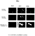
- FIG. 2 shows the results of experimental verification of the above-described difference in bubble formation.
- the result of this experiment is that a living body simulated body in which an aerated contrast agent is sealed in a water tank filled with deaerated water at 37 ° C. is left still, and only the bubble generation pulse is irradiated to the living body simulated body or only the bubble growth pulse is irradiated. It is the result of observing the state transition of the bubble on the echo screen when the bubble growth pulse is irradiated continuously after irradiation or the bubble generation pulse.
- the ultrasonic irradiation conditions used in this experiment are shown in Table 1.
- the biological simulated body is irradiated with a pulse that combines a bubble generation pulse and a growth pulse (lower part of FIG. 2)
- the bubble growth pulse is irradiated continuously after the bubble generation pulse irradiation.
- bubbles were generated at the focal position of the pulse (position indicated by two arrows in the figure) during the pulse irradiation, and a high luminance change occurred.
- this high luminance change persisted even after the pulse irradiation was completed. That is, it was found that bubbles having different persistence can be generated by irradiating the same ultrasonic contrast agent with different types of pulses.
- the inventors obtained the idea that the transient response of the aerated contrast agent is used for diagnosis and monitoring, and that the steady-state response is used for embolization treatment of tumor blood vessels. It came to invent the ultrasonic therapy apparatus used for embolization treatment of the administered subject.
- a transmission / reception sequence control unit that performs transmission / reception control of two types of ultrasonic pulses that transforms a bubbled contrast agent into a gas phase in a transient and steady state, and depicts blood flow to be treated
- the inventors have invented a monitoring unit that detects the generation of blood flow during treatment, and a feedback control unit that instructs the transmission / reception sequence control unit to perform additional treatment based on information provided by the monitoring unit.
- the frequency of the bubble generation pulse that causes transient vaporization is 0.5-10 MHz, and the pulse length is approximately within 2 ms, more preferably within 1 ms.
- the bubble growth pulse used for steady vaporization is not particularly limited as long as it is an ultrasonic irradiation condition capable of vibrating the bubbles generated by the bubble generation pulse.
- the frequency of the bubble generation pulse is approximately 0.5 to 10 MHz, and the pulse intensity is insufficient to vaporize the liquid of the contrast agent.
- the monitoring unit provided in the ultrasonic therapy device extracts the echo signal of the transient response of the aerated contrast agent and draws the capillary system around the tumor, which is difficult to visualize with a normal ultrasonic tomogram. Is desirable.
- the monitoring unit sets these blood vessels as treatment target regions and transmits position information to the feedback control unit.
- the feedback control unit outputs an instruction signal to the transmission / reception sequence control unit so as to transmit the stationary vaporization pulse together with the position information, and the transmission / reception sequence control unit receives the instruction signal and transmits the steady vaporization pulse. .
- the ultrasonic therapy apparatus periodically irradiates a treatment target region with a bubble generation pulse even during embolization treatment, and a signal derived from the generation of bubbles (hereinafter referred to as a “bubble-derived signal”). It is desirable to have a monitoring function to extract.
- the ultrasonic therapy apparatus can instruct the feedback control unit to perform additional irradiation of the bubble generation pulse and the bubble growth pulse for treatment based on the detection of the bubble-derived signal, The blood flow can be blocked again to enhance the effect of embolization treatment.
- the monitoring unit desirably has a function of detecting disappearance of bubbles in the treatment target region.
- This function extracts a signal having a signal intensity of a certain level or more as a bubble region from ultrasonic signals detected when a normal diagnostic imaging pulse is applied to the treatment target region. This can be realized by detecting reduction (disappearance).
- the ultrasonic therapy apparatus can instruct the feedback control unit to perform additional irradiation of the bubble generation pulse for the treatment and the bubble growth pulse when the disappearance of the bubble is detected. The effect of embolization treatment by regrowth can be enhanced.
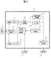
- FIG. 3 shows a configuration example of an ultrasonic treatment apparatus to which the above-described principle is applied.
- the ultrasonic treatment apparatus has a device configuration in which a probe 1, an input unit 3, and a display unit 4 are connected to a treatment machine main body 2.
- the treatment machine body 2 includes a transmission / reception sequence control unit 7, a reception beamformer 5, a transmission beamformer 6, a reception / transmission changeover switch 9, a reception processing unit 10, a tissue tomogram calculation unit 11, a monitoring unit 12, and a feedback control unit 13.
- the display data synthesis unit 8 is provided.
- the ultrasonic therapy apparatus obtains and displays a tomographic image of a diagnostic site of a subject to which a bubbled contrast agent has been administered in advance using pulsed ultrasound, and displays blood flow in a set treatment target region. It is blocked by bubbling of the bubbling contrast agent.
- the probe 1 is a device responsible for transmitting and receiving ultrasonic signals to and from the subject.
- the probe 1 only needs to be capable of transmitting and receiving ultrasonic waves that satisfy the conditions necessary for bubble formation (bubble generation) and bubble growth, and can also obtain a normal tissue tomographic image. Moreover, it is not necessary to be a single probe, and in some cases, a plurality of probes may be used in combination for each purpose.
- the input unit 3 is a console necessary for giving various instruction inputs by the user to the diagnostic machine body 2.
- a mouse, a stylus pen or other pointing device, a button, a keyboard or other input device is adopted as necessary.
- the transmission / reception sequence control unit 7 is a device that regulates the transmission conditions of pulsed ultrasonic waves. A specific method for defining the transmission conditions will be described later.
- the transmission beam former 6 forms a transmission beam based on the transmission conditions given from the transmission / reception sequence control unit 7 and also gives directivity to the transmission beam.
- the formed transmission beam is given to the probe 1 and transmitted to the subject as a transmission echo signal.
- the reception beamformer 5 is a device that gives reception directivity to the reception echo signal received by the probe 1 from the inside of the subject.
- the reception processing unit 10 is a device that detects a reception echo signal obtained by the reception beamformer 5.
- the received echo signal is finally transmitted to the display data synthesizing unit 8 after passing through the tissue tomographic image calculation unit 11 and provided to the display unit 4 as image data.
- the monitoring unit 12 is a device that extracts a bubble component from the received echo signal using a method described later and transmits the extraction result to the feedback control unit 13 as a bubble-derived signal.
- the feedback control unit 13 is a device that sets a treatment target region based on the bubble-derived signal and instructs the transmission / reception sequence control unit 7 on the transmission region of the transmission echo signal by a method described later.
- the monitoring unit 12 also has a function of detecting the presence or absence of blood flow based on a method described later and transmitting the detection result to the feedback control unit 13.
- the feedback control unit 13 also has a function of instructing the transmission / reception sequence control unit 7 to continuously irradiate the bubble generation pulse and the bubble growth pulse to the corresponding position based on the position information where the blood flow is detected.
- the acoustic impedance of the bubbles is about 0.0004 * 10 6 Z (Kg / m 2 / s), which is clearly different from blood (1.62z) and liver (1.64z). Therefore, when bubbles are generated in the treatment target region, the monitoring unit 12 detects a high-intensity echo signal.
- a bubble generation pulse for a time (hereinafter referred to as “one frame”) for acquiring one tomographic image between the irradiation of diagnostic ultrasonic waves for acquiring a tissue tomographic image. Irradiate.
- a significant change in luminance value due to the generation of bubbles is detected. At this time, if only signals having a luminance equal to or higher than a predetermined threshold set in advance are extracted, only the bubble component can be extracted.
- an imaging method capable of realizing a frame rate as high as possible is desirable in order to reduce the influence of body movement and the like.
- a method of dividing an imaging region in a raster direction and reconstructing an image while obtaining a difference can be considered.
- a method combined with an arithmetic function for correcting body movement is also effective.
- the monitoring unit 12 sets a treatment target region based on the bubble-derived signal extracted by the above-described method.
- the feedback control unit 13 extracts the position information of the treatment target region based on the depth and direction in which the bubble-derived signal is detected, and transmits it to the transmission / reception sequence control unit 7.
- one tissue tomogram is composed of a plurality of ultrasonic transmission / reception signals
- depth information of a treatment target region existing on each ultrasonic transmission / reception signal is extracted.
- the treatment target region of the ultrasonic transmission / reception signal 21 is c
- the treatment target region of the ultrasonic transmission / reception signal 22 is b
- the treatment target region of the ultrasonic transmission / reception signal 23 is a. It is.
- the transmission / reception sequence control unit 7 transmits the focused bubble generation pulse and the bubble growth pulse as one pulse continuously combined to the depth specified on each transmission / reception signal.
- the feedback control unit 13 is provided with a function of transmitting the position information where the generation or disappearance of the bubbles described above is detected to the transmission / reception sequence control unit 7.
- the transmission / reception sequence control unit 7 defines transmission conditions so as to emit a bubble generation pulse and a bubble growth pulse that are focused to a specified depth on each transmission / reception signal.
- FIG. 6 shows an example of a processing procedure executed when embolizing a tumor site with the ultrasonic therapy apparatus according to the embodiment.
- the probe 1 is applied from the body surface to a site that seems to be an affected part such as a tumor, and a bubble generation pulse is irradiated (SP2).
- SP2 a bubble generation pulse is irradiated
- the aerated contrast agent changes phase from a liquid to a bubble.
- the monitoring unit 12 determines whether or not a bubble-derived signal is included in the received echo signal (SP3), and sets a site where the bubble-derived signal is detected as a “treatment target region” (SP4).
- SP3 received echo signal
- SP4 treatment target region
- the display data synthesizing unit 8 displays an image of the bubble-derived echo received for the set treatment target region on the display unit 4 and displays an execution sign of embolization treatment start on the display unit 4 (SP5).
- the treatment setting area can be freely changed by setting the target area on the display screen.
- Setting or changing the treatment setting region is realized by the transmission / reception sequence control unit 7 receiving an operation input to the input unit 3 and transmitting / receiving an ultrasonic signal to / from the corresponding region.
- the ultrasonic diagnostic apparatus displays an error message on the screen of the display unit 4 (SP6).
- pulse ultrasound for embolization treatment that is, one pulse in which a bubble generation pulse and a bubble growth pulse are continuously transmitted
- the transmission of the pulse ultrasonic wave here means that the bubble generation pulse and the bubble growth pulse are transmitted as one pulse in time sequence.
- the normal diagnostic mode is entered.
- a diagnostic pulse is transmitted, and the presence or absence of disappearance of bubbles is monitored (SP12, SP13).
- the detected region is specified, and the bubble generation pulse and the bubble growth pulse are selectively irradiated only at the position (SP11).
- SP11 the processing of SP9-SP10 is executed again, and the blood flow blocking effect due to bubble growth is confirmed.
- a sign indicating that treatment is in progress is displayed on the display unit 4 (SP14).
- SP14 a determination process is performed to determine whether or not the arbitrary time set in advance by the user as the duration for the tumor embolization treatment is completed.
- SP15 A series of processing operations are repeatedly executed from the processing of SP8 (SP15).
- the ultrasonic therapy apparatus automatically shifts to a therapy end operation and displays a therapy end sign on the display unit 4 (SP16).
- the site where the target disease exists may be an abdominal organ (liver, pancreas, etc.), breast, thyroid gland, prostate, uterine fibroid.
- an organ such as a liver located at the deepest part of the body is a treatment region
- the attenuation rate of ultrasonic waves in vivo is 0.6 dB / MHz / cm and the allowable attenuation of ultrasonic waves is 6 dB
- bubbles are generated at a frequency of 0.6 MHz or less and about 0.5 MHz.
- bubble growth pulses in the case of a thyroid gland located at the shallowest part, the depth is about 1 cm, so it is desirable to generate a bubble generation pulse and a bubble growth pulse at a frequency of 10 MHz.
- MI Medical Index
- the intensity of the ultrasonic wave used as the bubble growth pulse is less than the strength of the bubble generation pulse, and it is desirable that the intensity is such that no bubble is generated when only the bubble growth pulse is irradiated. On the other hand, it is desirable that the bubble generation pulse has a short wavelength so as not to be affected by body movement. If the human respiration rate is 0.2Hz, there is no problem as long as it is within ms5ms, which is 1/1000.
- the present invention is not limited to the above-described embodiment as it is, and can be embodied by modifying constituent elements without departing from the scope of the invention in the implementation stage.
- it can be used in combination with an ultrasonic diagnostic function.
- various inventions can be formed by appropriately combining a plurality of constituent elements disclosed in the embodiments.
Landscapes
- Health & Medical Sciences (AREA)
- Engineering & Computer Science (AREA)
- Biomedical Technology (AREA)
- Nuclear Medicine, Radiotherapy & Molecular Imaging (AREA)
- Radiology & Medical Imaging (AREA)
- Life Sciences & Earth Sciences (AREA)
- Animal Behavior & Ethology (AREA)
- General Health & Medical Sciences (AREA)
- Public Health (AREA)
- Veterinary Medicine (AREA)
- Surgical Instruments (AREA)
- Ultra Sonic Daignosis Equipment (AREA)
- Thermotherapy And Cooling Therapy Devices (AREA)
Abstract
低侵襲かつ血流の遮断効果が高い塞栓治療を実現する超音波治療装置を提供する。このため、造影剤を気相化させる気泡生成パルスと、生成した気泡の径を増大させる気泡生成パルスを被検体の対象領域に送信する機能を備える超音波治療装置を提供する。
Description
本発明は超音波治療用装置に関する。例えば腫瘍などの疾患部位近辺の血管を塞栓させることにより治療効果を得る塞栓療法に使用する装置に関する。
日本国の3大疾患に挙げられる癌疾患の罹患率は、今日増加する一方であり、有用な早期診断・治療方法が強く望まれている。特に癌の所在をごく初期のうちに見つけることが可能な医用画像診断装置においては研究開発が活発に進められており、PET(positron emission tomography)、CT(Computed Tomography)、MRI(magnetic resonance imaging)、超音波など複数のモダリティにおいての技術の進歩はめざましい。しかしながら、早く発見できたとしても、手術や放射線治療などには高いリスク及び副作用が伴うため、治療へ踏み切る判断が難しい例が散見される。そのため、早期発見に合わせて侵襲性の低い治療法の研究開発が必須である。
そのような低侵襲治療の一つとして、塞栓療法の研究が進められている。塞栓療法は、栄養血管を遮断することによって局在する疾患、すなわち原発性腫瘍や子宮筋腫等を壊死させることで治療効果を得る治療法である。具体的には X線モニターの下で腫瘍の栄養血管までカテーテルを挿入して塞栓物質を注入し、血管を詰まらせる手法が用いられる。
しかし、この治療方法では、塞栓物質が他の正常組織へとつながる血管に詰まらせる可能性があり、正常組織をも壊死させてしまうリスクが常に存在する。さらに、この治療方法はカテーテルを用いるため、患者を局部又は全身麻酔下に置く必要性がある。また、この治療方法は、 X線をモニタリングに用いるため、必ずしも侵襲性が低いとは言えないとの指摘がある。
そこで、塞栓療法の侵襲性を低くするために、モニタリング法、塞栓物質及び物質の送達方法それぞれの観点からの開発が行なわれている。まず、塞栓物質として固体を用いるのではなく気泡を用いる方法が報告されている(特許文献1)。この方法は、 X線ではなく超音波を用いてのモニタリングが可能であり、被爆の低減が期待される。また、特許文献2には、液体の薬剤を生体内に予め投与しておき、対象部位に外部的刺激を与えて薬剤を気泡化させ、発生した気泡により腫瘍血流を途絶する手法が開示されている。また、特許文献3には、カテーテルを用いた塞栓物質の挿入を使用しない手法、すなわち収束した超音波を対象血管に照射し、血管を変性させることで血流を途絶させる手法が開示されている。さらに、特許文献4には、超音波エネルギーを用いて局所的に気泡を生成し、生成した気泡により塞栓療法を実現する手法が開示されている。
しかし、前述した全ての低侵襲塞栓療法は、治療の確実性に問題がある。例えば気泡を用いる方法において用いられるのは 1~ 5μm程度のマイクロバブルであるが、腫瘍内毛細血管系の直径は10~40μmであり、ましてや腫瘍へとつながる主要な動脈血管は 1mm以上であるため、これら血管を閉塞させるためには相当量の気泡を一定時間安定して存在させなければ効果を挙げることが困難である。気泡化物質を生体内に予め投与する場合にも原理的には同じ問題がある。また、超音波エネルギーを対象血管に照射して血管を変性させる場合にも、生体内における超音波の減衰の影響で超音波エネルギーが集束する位置とトランスデューサの幾何学的な焦点との間にずれが生じ易く、確実に一つの血管だけを変性させることが困難である。
以上のように、従来技術を用いる塞栓療法には、侵襲的が高い又は低侵襲であるが血流遮断効果が低いという問題がある。このため、本発明においては、低侵襲であり、かつ、血流遮断効果が高い塞栓治療が可能な装置の提供を目的とする。
発明者らは上記課題を解決すべく鋭意検討をおこなった結果、気泡化造影剤を気相化させる気泡生成パルスと、生成された気泡の径を増大させる気泡生成パルスを被検体の対象領域に送信する機能を備える装置を提供する。
本発明により、低侵襲かつ血流遮断効果が高い塞栓治療の実用化が可能になる。
(基本原理)
発明者らは、投与時には液体であるが超音波の照射によって気相化する特性を有する気泡化造影剤に照射する超音波を変化させる実験を通じ、超音波照射後に気泡が消失する過渡的気泡化状態と、超音波照射後も気泡が安定して存在し続ける定常的気泡化状態の2つがあることを見出した。以下、この現象を用いて血流遮断効果を高めるための基本原理を説明する。
発明者らは、投与時には液体であるが超音波の照射によって気相化する特性を有する気泡化造影剤に照射する超音波を変化させる実験を通じ、超音波照射後に気泡が消失する過渡的気泡化状態と、超音波照射後も気泡が安定して存在し続ける定常的気泡化状態の2つがあることを見出した。以下、この現象を用いて血流遮断効果を高めるための基本原理を説明する。
図1に、気泡化造影剤(相変化造影剤)が過渡的気泡化状態を経て定常的気泡化状態に成長する様子を模式的に示す。低沸点化合物を界面活性剤で微粒子化した気泡化造影剤に、造影剤を気相化させる気泡生成パルスを照射すると、内部の液体が超音波の作用により沸騰状態になり気化する(ステージa、b、c)。この気泡は準安定状態にあり、気泡生成パルスの照射を停止すると液相に戻る過渡的応答を示す(ステージf)。
発明者らは、この気泡生成パルスの照射に連続して、気泡を振動させる気泡成長パルスを準安定状態(ステージc)の気泡に照射することを試みた(ステージd)。すると、定常的に存在する径の大きい気泡が生成された(ステージe)。これは、周囲の媒質からの気体の取り込みや、周囲に存在する準安定気泡との合一により気泡の径が成長したことによると考えられる。この定常的気泡は体積対表面積の割合が準安定気泡よりも小さいため、より安定して存在し得る。以上の機序により、過渡的気泡化状態と定常的気泡化状態が生じることを発明者らは見出した。
図2に、上述した気泡化の違いを実験的に検証した結果を示す。本実験結果は、37℃の脱気水で満たされた水槽中に気泡化造影剤を封入した生体模擬体を静置し、生体模擬体に気泡生成パルスのみを照射、又は気泡成長パルスのみを照射、又は気泡生成パルスに連続して気泡成長パルスを照射した場合における気泡の状態遷移をエコー画面上で観察した結果である。本実験に用いた超音波の照射条件は表1の通りである。

まず、生体模擬体に気泡生成パルスのみを照射した場合(図2上段)を説明する。この場合は、パルスが照射されている間中、パルスの焦点位置(図中2つの矢印が示す位置)に気泡が生成し、高輝度の変化が発生した。しかし、照射終了と同時に高輝度は消失した。
次に、生体模擬体に気泡成長パルスのみを照射した場合(図2中段)を説明する。この場合、気泡成長パルスの焦点位置(図中2つの矢印が示す位置)には、特に何の変化も起こらなかった。
最後に、生体模擬体に気泡生成パルスと成長パルスを組み合わせたパルスを照射した場合(図2下段)を説明する。この場合は、図1で説明したように、気泡生成パルスの照射に連続して気泡成長パルスを照射する場合である。この場合、パルスの照射中にパルスの焦点位置(図中2つの矢印が示す位置)に気泡が生成し、高輝度変化が発生した。しかも、この高輝度変化は、パルスの照射終了後も持続した。すなわち、同じ超音波造影剤に、異なる種類のパルスを照射することで、持続性の異なる気泡を生成し得ることが分かった。
以上の実験結果を踏まえ、発明者らは、気泡化造影剤の過渡的応答を診断及びモニタリングに使用し、定常的応答を腫瘍血管の塞栓治療に使用するとの着想を得、気泡化造影剤を投与した被検体の塞栓治療に使用する超音波治療装置を発明するに至った。
具体的には、超音波治療装置として、気泡化造影剤を過渡的及び定常的に気相化させる2種類の超音波パルスの送受信制御を行なう送受信シークエンス制御部、治療対象となる血流を描出し、治療進行中には血流の発生を検出するモニタリング部、モニタリング部から与えられる情報に基づいて追加の治療を送受信シークエンス制御部に指示するフィードバック制御部を有するものを発明した。
ここで、過渡的気相化を起こす気泡生成パルスの周波数は0.5-10MHzであり、パルス長は概ね 2ms以内、更に望ましくは 1ms以内であることが望ましい。一方、定常的気相化に用いられる気泡成長パルスは、気泡生成パルスによって生成した気泡を振動させ得る超音波照射条件であれば特に制限はない。しかし、気泡生成パルスの周波数は概ね0.5-10MHzであり、パルス強度は、造影剤の液体を気相化するには足らない程度あることが望ましい。
また、超音波治療装置に具備されたモニタリング部では、気泡化造影剤の過渡的応答のエコー信号を抽出し、通常の超音波断層像では描出が困難な腫瘍周辺の毛細血管系を描出することが望ましい。モニタリング部は、これらの血管を治療対象領域として設定し、位置情報をフィードバック制御部に伝達する。フィードバック制御部は、位置情報と共に定常的気相化パルスを送信するように送受信シークエンス制御部に指示信号を出力し、その指示信号を受けて送受信シークエンス制御部は定常的気相化パルスを送信する。
安定気泡が生成された部位においては、血流が完全に遮断されて治療効果が発揮されることになるが、血流が生じた場合(すなわち治療が不完全な状態に陥った場合)、治療対象領域に血液と気泡化造影剤(液体)の流入が発生する。この血液の流入を検出するために、超音波治療装置は、塞栓治療中も気泡生成パルスを治療対象領域に周期的に照射し、気泡の生成に由来する信号(以下、「気泡由来信号」ともいう。)を抽出するモニタリング機能を有することが望ましい。この機能を有する場合、超音波治療装置は、気泡由来信号の検出に基づいてフィードバック制御部に対して治療用の気泡生成パルスと気泡成長パルスの追加的な照射を指示することが可能になり、血流を再度遮断して塞栓治療の効果を高めることができる。
なお、モニタリング部は、前述した気泡由来信号を検出する機能の他に、治療対象領域における気泡の消失を検出する機能を有することが望ましい。この機能は、通常の画像診断パルスを治療対象領域に照射した際に検出される超音波信号のうち一定以上の信号強度を有する信号を気泡領域として抽出し、気泡領域の時間差分によって気泡領域の縮小(消失)を検出することで実現できる。この機能を有する場合、超音波治療装置は、気泡の消失の検出時にフィードバック制御部に対して治療用の気泡生成パルスと気泡成長パルスの追加的な照射を指示することが可能になり、気泡の再成長による塞栓治療の効果を高めることができる。
以上の基本原理や仕組みを超音波治療装置に採用することにより、被験者の患部に直接針やカテーテルを注入することのない低侵襲な塞栓療法でありながら、血流の遮断効果を従来装置よりも高めることが可能になる。
(実施例)
以下、図面に基づいて、本発明の実施例を説明する。なお、後述する装置構成や処理動作の内容は発明を説明するための一例であり、本発明は、後述する装置構成や処理動作に既知の技術を組み合わせた発明や後述する装置構成や処理動作の一部を既知の技術と置換した発明も包含する。
以下、図面に基づいて、本発明の実施例を説明する。なお、後述する装置構成や処理動作の内容は発明を説明するための一例であり、本発明は、後述する装置構成や処理動作に既知の技術を組み合わせた発明や後述する装置構成や処理動作の一部を既知の技術と置換した発明も包含する。
図3に、前述の原理を適用した超音波治療装置の構成例を示す。超音波治療装置は、治療機本体2に探触子1、入力部3、表示部4を接続した装置構成を有している。治療機本体2は、送受信シークエンス制御部7、受信ビームフォーマ5、送信ビームフォーマ6、受信・送信切り替えスイッチ9、受波処理部10、組織断層像演算部11、モニタリング部12、フィードバック制御部13、表示データ合成部8を有している。
本実施例に係る超音波治療装置は、パルス超音波を利用して気泡化造影剤を予め投与した被検体の診断部位について断層像を得て表示し、設定された治療対象領域の血流を気泡化造影剤の気泡化により遮断するものである。
探触子1は被検体との間で超音波信号の送受信を担うデバイスである。探触子1は、気泡化(気泡の生成)及び気泡の成長に必要な条件を満たす超音波を送受信でき、かつ、通常の組織断層画像も得ることができるものであれば良い。また、単一の探触子である必要はなく、場合によっては複数の探触子をそれぞれの目的に応じて組み合わせて用いても良い。
入力部3はユーザによる各種の指示入力を、診断機本体2に与えるために必要なコンソールである。入力部3には、マウス、スタイラスペンその他のポインティングデバイス、ボタン、キーボードその他の入力装置を必要に応じて採用する。
なお、送受信シークエンス制御部7は、パルス超音波の送信条件を規定するデバイスである。送信条件の具体的な規定方法については後述する。送信ビームフォーマ6は、送受信シークエンス制御部7から与えられる送信条件に基づいて送信ビームを形成すると共に、送信ビームに指向性も与える。形成された送信ビームは探触子1に与えられ、送信エコー信号として被検体に送信される。
受信ビームフォーマ5は、探触子1が被検体内部から受信した受信エコー信号に受信指向性を与えるデバイスである。受波処理部10は、受信ビームフォーマ5で得られた受信エコー信号を検波するデバイスである。受信エコー信号は、組織断層像演算部11を経た後、最終的に表示データ合成部8へと送信され、画像データとして表示部4に提供される。
モニタリング部12は、後述する方法を用いて受信エコー信号から気泡成分を抽出し、抽出結果を気泡由来信号としてフィードバック制御部13に送信するデバイスである。フィードバック制御部13は、気泡由来信号に基づいて治療対象領域を設定すると共に、後述する方法により送受信シークエンス制御部7に送信エコー信号の送波領域を指示するデバイスである。なお、モニタリング部12は、後述する方法に基づいて血流の有無を検出し、検出結果をフィードバック制御部13に送信する機能も搭載する。フィードバック制御部13は、血流が検出された位置情報に基づいて、該当位置に対する気泡生成パルスと気泡成長パルスの連続照射を送受信シークエンス制御部7に指示する機能も搭載する。
次に、モニタリング部12で実行される気泡由来信号の抽出処理の一例を説明する。気泡の音響インピーダンスは約0.0004*106Z(Kg/m2/s)であり、血液(1.62z)や肝臓(1.64z)とは明らかな差を有している。従って、気泡が治療対象領域に生成すると、モニタリング部12では高強度のエコー信号が検出される。図4に示すように、組織断層像を取得するための診断用超音波の照射の合間に、1断層画像を取得するための時間分(以後、「1フレーム」と呼ぶ。)だけ気泡生成パルスを照射する。すると、図4に示すように、気泡が生成したことによる輝度値の大幅な変化が検出される。この際、予め設定しておいた一定の閾値以上の輝度を持つ信号だけを抽出すると、気泡成分のみを抽出することができる。
このように画像間の相関処理を用いるには、体動等による影響を低減するため、なるべく高いフレームレートを実現できる撮像方法が望ましい。一つの方法としては、治療対象領域を設定する場合に、ラスター方向に撮像領域を分割し、差分を求めながら画像を再構築する方法が考えられる。また、体動を補正する演算機能等と組み合わせる方法も効果的である。更に、モニタリング部12は、上述した手法で抽出した気泡由来信号に基づいて治療対象領域を設定する。
フィードバック制御部13は、図5に示したように、気泡由来信号が検出された深さと方位に基づいて治療対象領域の位置情報を抽出し、送受信シークエンス制御部7に伝達する。1組織断層像は、複数の超音波送受信から構成されているが、各々の超音波送受信信号上に存在する治療対象領域の深さ情報が抽出される。図5中、斜線部位が治療対象領域であるとすると、超音波送受信信号21の治療対象領域はc、超音波送受信信号22の治療対象領域はb、超音波送受信信号23の治療対象領域はaである。送受信シークエンス制御部7は、各々の送受信信号上で指定された深さに対し、集束させた気泡生成パルス及び気泡成長パルスを連続的に組み合わせた1つのパルスとして送信する。
次に、モニタリング部12で実行される血流検出方法の例を説明する。安定気泡を生成した状態の治療対象領域に気泡生成パルスを照射したとしても、安定気泡が生成しているところでは大きな輝度変化は起こらないと予測されるが、新たに過渡的気泡が生成されるような部位では大きな輝度上昇が起こると予測される。従って、フレーム間で輝度値の変化を追跡し、予め設定した一定の閾値以上の輝度信号の上昇が抽出されれば、新たな気泡の生成を検出することができる。このことは、治療対象領域に生じた新たな血流が検出できたことを意味する。この場合には、治療効果を高めるため、該当領域に気泡生成パルスと気泡成長パルスを連続的に照射するようにフィードバック制御する。
続いて、モニタリング部12で実行される他の血流検出方法の例を説明する。前述したように、生体と気泡の音響インピーダンスの差に着目すると、存在する気泡が消失した場合には輝度値の大幅な低減が起こることが予想される。従って、フレーム間で輝度値の変化を追跡し、予め設定した一定の閾値以上の輝度信号の低減が抽出されれば、気泡の消失を検出することができる。このことは治療効果の低下を意味するので、該当領域に気泡生成パルスと気泡成長パルスを連続的に照射するようにフィードバック制御する。
フィードバック制御部13には、前述した気泡の生成や消失が検出された位置情報を、送受信シークエンス制御部7に伝達する機能を実装する。送受信シークエンス制御部7は、各々の送受信信号上で指定された深さに集束させた気泡生成パルス及び気泡成長パルスを射出するように送信条件を規定する。
図6に、実施例に係る超音波治療装置によって腫瘍部位を塞栓治療する場合に実行される処理手順の例を示す。気泡化造影剤を被検体に投与した後(SP1)、腫瘍などの患部と思われる部位に体表から探触子1をあて、気泡生成パルスを照射する(SP2)。気泡化造影剤が存在する部位では、気泡化造影剤が液体から気泡に相変化する。モニタリング部12は、受信エコー信号に気泡由来信号が含まれるか否かを判定し(SP3)、気泡由来信号が検出された部位を「治療対象領域」に設定する(SP4)。また、表示データ合成部8は、設定された治療対象領域について受信された気泡由来エコーの画像を表示部4に表示すると共に、塞栓治療の開始の実行サインを表示部4に表示する(SP5)。なお、治療設定領域は、表示画面上における対象領域の設定入力より自由に変更することができる。治療設定領域の設定又は変更は、入力部3に対する操作入力を送受信シークエンス制御部7が受け付け、該当領域との間で超音波信号を送受することで実現される。因みに、気泡化造影剤の気泡化に由来する信号が検出されない場合には、気泡化造影剤の投与不足、探触子1の当て方等の問題が考えられる。このため、超音波診断装置は、表示部4の画面上にエラーメッセージを表示する(SP6)。
治療対象領域に対する塞栓治療が開始されると、治療対象領域に向けて塞栓治療用のパルス超音波(すなわち、気泡生成パルスと気泡成長パルスを連続させた1つのパルス)が連続的に送信される(SP7)。ここでのパルス超音波の送信は、気泡生成パルスと気泡成長パルスが時間順次に1つのパルスとして送信されることを意味する。
塞栓治療が開始すると、治療モニター(ループ処理)が開始される(SP8)。治療モニターの開始後は、気泡生成パルスのみで構成されるパルス超音波が単発的に照射される(SP9)。並行して、受信エコー信号に気泡由来信号が検出されるか否かが判定され、当該信号が検出された場合(新しい血流の存在が検出された場合)には、検出領域にのみ気泡生成パルスと気泡成長パルスが照射される(SP10、SP11)。このSP9-SP10-SP11に係る処理は、気泡由来信号が検出されなくなるまで繰り返し実行される。
新しい血流が存在しなくなると、通常の診断モードに移行する。診断モードを開始すると、診断パルスが送信され、気泡の消失の有無がモニタリングされる(SP12、SP13)。気泡の消失が検出された場合(治療効果が低下している場合)、検出された領域を特定すると共に、当該位置にのみ気泡生成パルスと気泡成長パルスを選択的に照射する(SP11)。なお、SP11の実行後は、再びSP9-SP10の処理が実行され、気泡の成長による血流の遮断効果が確認される。これらの検出、判定、制御動作は、モニタリング部12やフィードバック制御部13を通じて実行される。
気泡の消失が検出されなかった場合は、治療進行中のサインが表示部4に表示される(SP14)。このSP14の処理の実行後、腫瘍塞栓治療のための継続時間としてユーザが事前に設定した任意時間が終了したか否かの判定処理が実行され、任意時間が終了していない間は、前述したSP8の処理から一連の処理動作が繰り返し実行される(SP15)。一方、任意時間の終了が検出された場合には、超音波治療装置は、自動的に治療終了動作に移行し、治療終了サインを表示部4に表示する(SP16)。
(他の実施例)
前述の実施例においては、表1に示す生成条件に基づいて、気泡生成パルスと気泡成長パルスを生成する場合について説明した。しかしながら、気泡生成パルスと気泡成長パルスの生成条件はこれに限らない。治療対象領域の体表からの深さによって最適な生成条件も異なるためである。
前述の実施例においては、表1に示す生成条件に基づいて、気泡生成パルスと気泡成長パルスを生成する場合について説明した。しかしながら、気泡生成パルスと気泡成長パルスの生成条件はこれに限らない。治療対象領域の体表からの深さによって最適な生成条件も異なるためである。
例えば対象疾患が存在する部位には、腹部臓器(肝臓、すい臓、等)、乳房、甲状腺、前立腺、子宮筋腫などが考えられる。これらのうち、体内の一番深部に位置する肝臓などの臓器が治療領域となる場合、体表から10-15cm程度の深部において気泡を生成し成長させる必要性がある。超音波の生体内での減衰率を0.6dB/MHz/cm、許容し得る超音波の減衰を6 dBとすると、深さ15cmの場合、0.6MHz以下、0.5MHz程度の周波数で気泡生成パルス及び気泡成長パルスを生成することが望ましい。逆に、最浅部に位置する甲状腺などの場合、深さ1cm程度であるから10MHzの周波数で気泡生成パルス及び気泡成長パルスを生成することが望ましい。
因みに、気泡生成パルスは、それ自体は生体に影響がない超音波強度で照射することが望ましい。指標として、Medical Index(MI)値(=Pneg/√f)が、焦点領域で 1.9以下であることが望ましい。ただし、Pnegは最大負圧であり、fは中心周波数である。
気泡成長パルスとして使用される超音波の強度は気泡生成パルスの強度以下であり、気泡成長パルスのみを照射したときに気泡生成しない強度であることが望ましい。一方、気泡生成パルスは、体動の影響を受けない程度に短い波長であることが望ましい。人間の呼吸の速度が 0.2Hzとした場合、その 1/1000である 5ms以内であれば問題ない。
なお、本発明は上記実施形態そのままに限定されるものではなく、実施段階ではその要旨を逸脱しない範囲で構成要素を変形して具体化できる。例えば超音波診断機能と組み合わせて使用することもできる。また、実施例に開示されている複数の構成要素の適宜な組み合わせにより、数々の発明を形成することができる。
1…探触子
2…治療機本体
3…入力部
4…表示部
5…受信ビームフォーマ
6…送信ビームフォーマ
7…送受信シークエンス制御部
8…表示データ合成部
9…受信・送信切替スイッチ
10…受波処理部
11…組織断層像演算部
12…モニタリグ部
13…フィードバック制御部
2…治療機本体
3…入力部
4…表示部
5…受信ビームフォーマ
6…送信ビームフォーマ
7…送受信シークエンス制御部
8…表示データ合成部
9…受信・送信切替スイッチ
10…受波処理部
11…組織断層像演算部
12…モニタリグ部
13…フィードバック制御部
Claims (9)
- 投与時には液体であるが超音波の照射により気相化する気泡化造影剤を使用する超音波治療装置であって、
前記気泡化造影剤を気泡化させる気泡生成パルス及び生成された気泡の径を増大させる気泡成長パルスを生成する送信ビームを生成する送信ビームフォーマと、
前記気泡生成パルス及び又は前記気泡成長パルスを被検体の対象領域に送信する探触子と
を有する超音波治療装置。 - 請求項1に記載の超音波治療装置において、
前記気泡生成パルス、前記気泡成長パルス及び診断用パルスの切り替えを制御する送受信シークエンス制御部
を更に有することを特徴とする超音波治療装置。 - 請求項2に記載の超音波治療装置において、
前記対象領域における血流の有無を検出するモニタリング部と、
前記モニタリング部において血流の発生が検出された場合、当該検出部位にのみ前記気泡生成パルスと前記気泡成長パルスが送信されるように前記送受信シークエンス制御部に通知するフィードバック制御部と
を更に有することを特徴とする超音波治療装置。 - 請求項2に記載の超音波治療装置において、
前記送受信シークエンス制御部は、前記気泡生成パルスのみの送信と、前記気泡生成パルスに前記気泡成長パルスを連続させた1つのパルスの送信を切り替え制御する
ことを特徴とする超音波治療装置。 - 請求項1に記載の超音波治療装置において、
前記気泡生成パルスの中心周波数は 0.5-10MHzであり、パルス長は 5ms以内である
ことを特徴とする超音波治療装置。 - 請求項1に記載の超音波治療装置において、
前記気泡成長パルスの中心周波数は 0.5-10MHzであり、パルス強度は前記気泡化造影剤を気相化するには足らない
ことを特徴とする超音波治療装置。 - 請求項1に記載の超音波治療装置において、
治療開始後の前記対象領域に前記気泡生成パルスのみを照射し、当該対象領域から新たな気泡の生成に起因した超音波信号が検出されるか否かに基づいて血流の有無を検出するモニタリング部
を有することを特徴とする超音波治療装置。 - 請求項1に記載の超音波治療装置において、
診断用パルスを照射した際に検出される前記対象領域から検出される超音波信号から気泡成分信号を抽出すると共に、当該気泡成分信号の時間差分に基づいて気泡の消失の有無を検出するモニタリング部
を有することを特徴とする超音波治療装置。 - 請求項8に記載の超音波治療装置において、
前記モニタリング部において血流の消失が検出された場合、当該検出部位にのみ前記気泡生成パルスと前記気泡成長パルスが送信されるように前記送受信シークエンス制御部に通知するフィードバック制御部
を更に有することを特徴とする超音波治療装置。
Priority Applications (3)
| Application Number | Priority Date | Filing Date | Title |
|---|---|---|---|
| US13/395,198 US9067053B2 (en) | 2009-12-04 | 2010-12-01 | Ultrasonic treatment device |
| CN201080040199.0A CN102481164B (zh) | 2009-12-04 | 2010-12-01 | 超声波治疗装置 |
| EP10834558.8A EP2508142A4 (en) | 2009-12-04 | 2010-12-01 | Ultrasonic treatment device |
Applications Claiming Priority (2)
| Application Number | Priority Date | Filing Date | Title |
|---|---|---|---|
| JP2009-276731 | 2009-12-04 | ||
| JP2009276731A JP4734448B2 (ja) | 2009-12-04 | 2009-12-04 | 超音波治療装置 |
Publications (1)
| Publication Number | Publication Date |
|---|---|
| WO2011068108A1 true WO2011068108A1 (ja) | 2011-06-09 |
Family
ID=44114954
Family Applications (1)
| Application Number | Title | Priority Date | Filing Date |
|---|---|---|---|
| PCT/JP2010/071428 Ceased WO2011068108A1 (ja) | 2009-12-04 | 2010-12-01 | 超音波治療装置 |
Country Status (5)
| Country | Link |
|---|---|
| US (1) | US9067053B2 (ja) |
| EP (1) | EP2508142A4 (ja) |
| JP (1) | JP4734448B2 (ja) |
| CN (1) | CN102481164B (ja) |
| WO (1) | WO2011068108A1 (ja) |
Families Citing this family (26)
| Publication number | Priority date | Publication date | Assignee | Title |
|---|---|---|---|---|
| AU2010289775B2 (en) | 2009-08-26 | 2016-02-04 | Histosonics, Inc. | Devices and methods for using controlled bubble cloud cavitation in fractionating urinary stones |
| AU2010289769B2 (en) | 2009-08-26 | 2016-06-30 | Histosonics, Inc. | Micromanipulator control arm for therapeutic and imaging ultrasound transducers |
| WO2012048335A2 (en) | 2010-10-08 | 2012-04-12 | The University Of North Carolina At Chapel Hill | Formulation of acoustically activatable particles having low vaporization energy and methods for using same |
| US9144694B2 (en) | 2011-08-10 | 2015-09-29 | The Regents Of The University Of Michigan | Lesion generation through bone using histotripsy therapy without aberration correction |
| US9636133B2 (en) | 2012-04-30 | 2017-05-02 | The Regents Of The University Of Michigan | Method of manufacturing an ultrasound system |
| US9982290B2 (en) | 2012-10-04 | 2018-05-29 | The University Of North Carolina At Chapel Hill | Methods and systems for using encapsulated microbubbles to process biological samples |
| US20140100459A1 (en) | 2012-10-05 | 2014-04-10 | The Regents Of The University Of Michigan | Bubble-induced color doppler feedback during histotripsy |
| JP5998017B2 (ja) * | 2012-11-09 | 2016-09-28 | 株式会社日立製作所 | 超音波治療装置及び超音波治療支援システム |
| MX369950B (es) * | 2013-07-03 | 2019-11-27 | Histosonics Inc | Secuencias de excitacion de histotripsia optimizadas para formacion de nube de burbujas usando dispersion de choque. |
| WO2015003154A1 (en) | 2013-07-03 | 2015-01-08 | Histosonics, Inc. | Articulating arm limiter for cavitational ultrasound therapy system |
| WO2015027164A1 (en) | 2013-08-22 | 2015-02-26 | The Regents Of The University Of Michigan | Histotripsy using very short ultrasound pulses |
| US20160262727A1 (en) * | 2013-11-08 | 2016-09-15 | The University Of North Carolina At Chapel Hill | Acoustic detection of activated phase-change contrast agent |
| WO2016210133A1 (en) | 2015-06-24 | 2016-12-29 | The Regents Of The Universtiy Of Michigan | Histotripsy therapy systems and methods for the treatment of brain tissue |
| US12551732B2 (en) | 2016-05-02 | 2026-02-17 | University Of Kansas | Method and apparatus for removing microvessels |
| US11511138B2 (en) | 2016-05-02 | 2022-11-29 | University Of Kansas | Method and apparatus for removing microvessels |
| CN110300550B (zh) * | 2017-02-28 | 2021-12-07 | 奥林巴斯株式会社 | 超声波医疗装置 |
| CA3120586A1 (en) | 2018-11-28 | 2020-06-04 | Histosonics, Inc. | Histotripsy systems and methods |
| KR102291528B1 (ko) * | 2019-09-02 | 2021-08-19 | 아주대학교산학협력단 | 초음파와 버블 생성 물질 주입장치를 이용한 광학 치료장치 |
| JP2023513012A (ja) | 2020-01-28 | 2023-03-30 | ザ リージェンツ オブ ザ ユニバーシティー オブ ミシガン | ヒストトリプシー免疫感作のためのシステムおよび方法 |
| BR112022025722A2 (pt) | 2020-06-18 | 2023-03-07 | Histosonics Inc | Sistemas e métodos de acoplamento acústico e paciente de histotripsia |
| CN116056759A (zh) * | 2020-08-24 | 2023-05-02 | 叶秩光 | 超声波搭配微气泡辅助的气球导管系统及其血管扩张方法 |
| CN116782843A (zh) | 2020-08-27 | 2023-09-19 | 密歇根大学董事会 | 用于组织摧毁术的具有发射-接收能力的超声换能器 |
| US12582848B2 (en) | 2021-06-07 | 2026-03-24 | The Regents Of The University Of Michigan | Minimally invasive histotripsy systems and methods |
| EP4351447A4 (en) | 2021-06-07 | 2025-07-16 | Univ Michigan Regents | ALL-IN-ONE ULTRASOUND SYSTEMS AND METHODS INCLUDING HISTOTRIPSY |
| WO2024092272A1 (en) | 2022-10-28 | 2024-05-02 | Histosonics, Inc. | Histotripsy systems and methods |
| KR20260003742A (ko) | 2023-04-20 | 2026-01-07 | 히스토소닉스, 인크. | 치료 계획 및 요법을 위한 사용자 인터페이스들 및 작업 흐름들을 포함하는 히스토트립시 시스템들 및 연관된 방법들 |
Citations (3)
| Publication number | Priority date | Publication date | Assignee | Title |
|---|---|---|---|---|
| JP2003033365A (ja) * | 2001-07-23 | 2003-02-04 | Hitachi Ltd | 超音波治療装置 |
| WO2004100811A1 (ja) * | 2003-05-19 | 2004-11-25 | Hitachi, Ltd. | 超音波治療装置 |
| JP2008024604A (ja) * | 2006-07-18 | 2008-02-07 | Hitachi Ltd | 気泡生成剤 |
Family Cites Families (15)
| Publication number | Priority date | Publication date | Assignee | Title |
|---|---|---|---|---|
| US7686763B2 (en) * | 1998-09-18 | 2010-03-30 | University Of Washington | Use of contrast agents to increase the effectiveness of high intensity focused ultrasound therapy |
| US7687039B2 (en) * | 1998-10-28 | 2010-03-30 | Covaris, Inc. | Methods and systems for modulating acoustic energy delivery |
| WO2001066016A1 (en) | 2000-03-06 | 2001-09-13 | Scimed Life Systems, Inc. | Embolic agents visible under ultrasound |
| US6793626B2 (en) * | 2001-01-17 | 2004-09-21 | Fuji Photo Film Co., Ltd. | Ultrasonic scatterer, ultrasonic imaging method and ultrasonic imaging apparatus |
| WO2004069153A2 (en) * | 2003-01-27 | 2004-08-19 | Medrad, Inc. | Apparatus, system and method for generating bubbles on demand |
| JP2005081073A (ja) * | 2003-09-11 | 2005-03-31 | Toshiba Corp | 超音波診断装置 |
| EP1711109B1 (en) | 2004-02-06 | 2013-05-08 | Technion Research And Development Foundation Ltd. | Localized production of microbubbles and control of cavitational and heating effects by use of enhanced ultrasound |
| GB2417080B (en) * | 2004-08-13 | 2008-05-21 | Stichting Tech Wetenschapp | Intravascular ultrasound techniques |
| WO2006051542A1 (en) * | 2004-11-12 | 2006-05-18 | Kpe Ltd. | Nanoparticle mediated ultrasound therapy and diagnostic imaging |
| JP4630127B2 (ja) | 2005-05-17 | 2011-02-09 | 株式会社日立製作所 | 超音波診断治療装置 |
| JP4686269B2 (ja) | 2005-06-22 | 2011-05-25 | 株式会社日立メディコ | 超音波治療装置 |
| JP4369907B2 (ja) * | 2005-07-01 | 2009-11-25 | 株式会社日立製作所 | 音響化学治療装置 |
| US8257338B2 (en) * | 2006-10-27 | 2012-09-04 | Artenga, Inc. | Medical microbubble generation |
| CN101164533A (zh) * | 2006-10-19 | 2008-04-23 | 深圳市一体医疗科技有限公司 | 一种声学造影剂的新用途 |
| JP5162923B2 (ja) * | 2007-02-27 | 2013-03-13 | 株式会社日立製作所 | 超音波撮像装置 |
-
2009
- 2009-12-04 JP JP2009276731A patent/JP4734448B2/ja not_active Expired - Fee Related
-
2010
- 2010-12-01 US US13/395,198 patent/US9067053B2/en not_active Expired - Fee Related
- 2010-12-01 CN CN201080040199.0A patent/CN102481164B/zh active Active
- 2010-12-01 WO PCT/JP2010/071428 patent/WO2011068108A1/ja not_active Ceased
- 2010-12-01 EP EP10834558.8A patent/EP2508142A4/en not_active Withdrawn
Patent Citations (3)
| Publication number | Priority date | Publication date | Assignee | Title |
|---|---|---|---|---|
| JP2003033365A (ja) * | 2001-07-23 | 2003-02-04 | Hitachi Ltd | 超音波治療装置 |
| WO2004100811A1 (ja) * | 2003-05-19 | 2004-11-25 | Hitachi, Ltd. | 超音波治療装置 |
| JP2008024604A (ja) * | 2006-07-18 | 2008-02-07 | Hitachi Ltd | 気泡生成剤 |
Also Published As
| Publication number | Publication date |
|---|---|
| JP4734448B2 (ja) | 2011-07-27 |
| EP2508142A1 (en) | 2012-10-10 |
| CN102481164B (zh) | 2015-01-14 |
| JP2011115461A (ja) | 2011-06-16 |
| EP2508142A4 (en) | 2017-05-03 |
| US9067053B2 (en) | 2015-06-30 |
| CN102481164A (zh) | 2012-05-30 |
| US20120172720A1 (en) | 2012-07-05 |
Similar Documents
| Publication | Publication Date | Title |
|---|---|---|
| JP4734448B2 (ja) | 超音波治療装置 | |
| US7722539B2 (en) | Treatment of unwanted tissue by the selective destruction of vasculature providing nutrients to the tissue | |
| Elhelf et al. | High intensity focused ultrasound: The fundamentals, clinical applications and research trends | |
| JP6568057B2 (ja) | 虚血性発作の超音波治療のための装置及び方法 | |
| US9078594B2 (en) | Ultrasound diagnostic and treatment device | |
| US7686763B2 (en) | Use of contrast agents to increase the effectiveness of high intensity focused ultrasound therapy | |
| Suo et al. | Thrombolysis using multi-frequency high intensity focused ultrasound at MHz range: an in vitro study | |
| Chen et al. | Mechanisms of lesion formation in high intensity focused ultrasound therapy | |
| JP4686269B2 (ja) | 超音波治療装置 | |
| JP2009508649A (ja) | パルス・キャビテーション超音波療法 | |
| CN102946808B (zh) | 经皮穿刺针、血管内导管和其它介入式设备的超声可视化 | |
| CN101252970B (zh) | 具有治疗换能器放大器的组合成像和治疗换能器 | |
| CN101829326A (zh) | 微泡在制备用于联合超声产生高强度空化作为抗肿瘤新生血管药物的用途 | |
| JP2018538056A (ja) | 超音波血栓溶解用及び血管音響共振器を介した他の治療用のインターリーブビームパターン | |
| N'Djin et al. | Utility of a tumor-mimic model for the evaluation of the accuracy of HIFU treatments. results of in vitro experiments in the liver | |
| JP5161955B2 (ja) | 超音波照射装置 | |
| Crum et al. | Therapeutic ultrasound: Recent trends and future perspectives | |
| JP2014502533A (ja) | 微小気泡ベースの造影剤による光音響信号強調 | |
| Ashida et al. | Transluminal approach with bubble-seeded histotripsy for cancer treatment with ultrasonic mechanical effects | |
| Yang et al. | Hemocoagulase combined with microbubble-enhanced ultrasound cavitation for augmented ablation of microvasculature in rabbit VX2 liver tumors | |
| TWI432182B (zh) | 將大分子物質導入活體標靶細胞之系統 | |
| JP4387947B2 (ja) | 超音波治療装置 | |
| JP6316420B2 (ja) | 超音波照射装置 | |
| Rodrigues et al. | Oncologic applications of magnetic resonance guided focused ultrasound | |
| JP2014117550A (ja) | 医療システム |
Legal Events
| Date | Code | Title | Description |
|---|---|---|---|
| WWE | Wipo information: entry into national phase |
Ref document number: 201080040199.0 Country of ref document: CN |
|
| 121 | Ep: the epo has been informed by wipo that ep was designated in this application |
Ref document number: 10834558 Country of ref document: EP Kind code of ref document: A1 |
|
| WWE | Wipo information: entry into national phase |
Ref document number: 13395198 Country of ref document: US Ref document number: 2010834558 Country of ref document: EP |
|
| NENP | Non-entry into the national phase |
Ref country code: DE |